EP2754893A1 - Method for assembling shafting of regenerated energy power generation device, and tool for assembling shafting - Google Patents
Method for assembling shafting of regenerated energy power generation device, and tool for assembling shafting Download PDFInfo
- Publication number
- EP2754893A1 EP2754893A1 EP12880049.7A EP12880049A EP2754893A1 EP 2754893 A1 EP2754893 A1 EP 2754893A1 EP 12880049 A EP12880049 A EP 12880049A EP 2754893 A1 EP2754893 A1 EP 2754893A1
- Authority
- EP
- European Patent Office
- Prior art keywords
- bearing
- rotation shaft
- inner race
- spacer
- shafting
- Prior art date
- Legal status (The legal status is an assumption and is not a legal conclusion. Google has not performed a legal analysis and makes no representation as to the accuracy of the status listed.)
- Granted
Links
Images






Classifications
-
- F—MECHANICAL ENGINEERING; LIGHTING; HEATING; WEAPONS; BLASTING
- F03—MACHINES OR ENGINES FOR LIQUIDS; WIND, SPRING, OR WEIGHT MOTORS; PRODUCING MECHANICAL POWER OR A REACTIVE PROPULSIVE THRUST, NOT OTHERWISE PROVIDED FOR
- F03B—MACHINES OR ENGINES FOR LIQUIDS
- F03B13/00—Adaptations of machines or engines for special use; Combinations of machines or engines with driving or driven apparatus; Power stations or aggregates
- F03B13/12—Adaptations of machines or engines for special use; Combinations of machines or engines with driving or driven apparatus; Power stations or aggregates characterised by using wave or tide energy
- F03B13/26—Adaptations of machines or engines for special use; Combinations of machines or engines with driving or driven apparatus; Power stations or aggregates characterised by using wave or tide energy using tide energy
- F03B13/264—Adaptations of machines or engines for special use; Combinations of machines or engines with driving or driven apparatus; Power stations or aggregates characterised by using wave or tide energy using tide energy using the horizontal flow of water resulting from tide movement
-
- F—MECHANICAL ENGINEERING; LIGHTING; HEATING; WEAPONS; BLASTING
- F03—MACHINES OR ENGINES FOR LIQUIDS; WIND, SPRING, OR WEIGHT MOTORS; PRODUCING MECHANICAL POWER OR A REACTIVE PROPULSIVE THRUST, NOT OTHERWISE PROVIDED FOR
- F03B—MACHINES OR ENGINES FOR LIQUIDS
- F03B17/00—Other machines or engines
- F03B17/06—Other machines or engines using liquid flow with predominantly kinetic energy conversion, e.g. of swinging-flap type, "run-of-river", "ultra-low head"
- F03B17/061—Other machines or engines using liquid flow with predominantly kinetic energy conversion, e.g. of swinging-flap type, "run-of-river", "ultra-low head" with rotation axis substantially in flow direction
-
- F—MECHANICAL ENGINEERING; LIGHTING; HEATING; WEAPONS; BLASTING
- F03—MACHINES OR ENGINES FOR LIQUIDS; WIND, SPRING, OR WEIGHT MOTORS; PRODUCING MECHANICAL POWER OR A REACTIVE PROPULSIVE THRUST, NOT OTHERWISE PROVIDED FOR
- F03D—WIND MOTORS
- F03D13/00—Assembly, mounting or commissioning of wind motors; Arrangements specially adapted for transporting wind motor components
- F03D13/10—Assembly of wind motors; Arrangements for erecting wind motors
-
- F—MECHANICAL ENGINEERING; LIGHTING; HEATING; WEAPONS; BLASTING
- F03—MACHINES OR ENGINES FOR LIQUIDS; WIND, SPRING, OR WEIGHT MOTORS; PRODUCING MECHANICAL POWER OR A REACTIVE PROPULSIVE THRUST, NOT OTHERWISE PROVIDED FOR
- F03D—WIND MOTORS
- F03D15/00—Transmission of mechanical power
-
- F—MECHANICAL ENGINEERING; LIGHTING; HEATING; WEAPONS; BLASTING
- F03—MACHINES OR ENGINES FOR LIQUIDS; WIND, SPRING, OR WEIGHT MOTORS; PRODUCING MECHANICAL POWER OR A REACTIVE PROPULSIVE THRUST, NOT OTHERWISE PROVIDED FOR
- F03D—WIND MOTORS
- F03D80/00—Details, components or accessories not provided for in groups F03D1/00 - F03D17/00
- F03D80/70—Bearing or lubricating arrangements
-
- F—MECHANICAL ENGINEERING; LIGHTING; HEATING; WEAPONS; BLASTING
- F03—MACHINES OR ENGINES FOR LIQUIDS; WIND, SPRING, OR WEIGHT MOTORS; PRODUCING MECHANICAL POWER OR A REACTIVE PROPULSIVE THRUST, NOT OTHERWISE PROVIDED FOR
- F03D—WIND MOTORS
- F03D80/00—Details, components or accessories not provided for in groups F03D1/00 - F03D17/00
- F03D80/80—Arrangement of components within nacelles or towers
- F03D80/88—Arrangement of components within nacelles or towers of mechanical components
-
- F—MECHANICAL ENGINEERING; LIGHTING; HEATING; WEAPONS; BLASTING
- F03—MACHINES OR ENGINES FOR LIQUIDS; WIND, SPRING, OR WEIGHT MOTORS; PRODUCING MECHANICAL POWER OR A REACTIVE PROPULSIVE THRUST, NOT OTHERWISE PROVIDED FOR
- F03D—WIND MOTORS
- F03D9/00—Adaptations of wind motors for special use; Combinations of wind motors with apparatus driven thereby; Wind motors specially adapted for installation in particular locations
- F03D9/20—Wind motors characterised by the driven apparatus
- F03D9/28—Wind motors characterised by the driven apparatus the apparatus being a pump or a compressor
-
- F—MECHANICAL ENGINEERING; LIGHTING; HEATING; WEAPONS; BLASTING
- F16—ENGINEERING ELEMENTS AND UNITS; GENERAL MEASURES FOR PRODUCING AND MAINTAINING EFFECTIVE FUNCTIONING OF MACHINES OR INSTALLATIONS; THERMAL INSULATION IN GENERAL
- F16C—SHAFTS; FLEXIBLE SHAFTS; ELEMENTS OR CRANKSHAFT MECHANISMS; ROTARY BODIES OTHER THAN GEARING ELEMENTS; BEARINGS
- F16C19/00—Bearings with rolling contact, for exclusively rotary movement
- F16C19/54—Systems consisting of a plurality of bearings with rolling friction
- F16C19/546—Systems with spaced apart rolling bearings including at least one angular contact bearing
-
- F—MECHANICAL ENGINEERING; LIGHTING; HEATING; WEAPONS; BLASTING
- F16—ENGINEERING ELEMENTS AND UNITS; GENERAL MEASURES FOR PRODUCING AND MAINTAINING EFFECTIVE FUNCTIONING OF MACHINES OR INSTALLATIONS; THERMAL INSULATION IN GENERAL
- F16C—SHAFTS; FLEXIBLE SHAFTS; ELEMENTS OR CRANKSHAFT MECHANISMS; ROTARY BODIES OTHER THAN GEARING ELEMENTS; BEARINGS
- F16C35/00—Rigid support of bearing units; Housings, e.g. caps, covers
- F16C35/04—Rigid support of bearing units; Housings, e.g. caps, covers in the case of ball or roller bearings
- F16C35/042—Housings for rolling element bearings for rotary movement
-
- F—MECHANICAL ENGINEERING; LIGHTING; HEATING; WEAPONS; BLASTING
- F16—ENGINEERING ELEMENTS AND UNITS; GENERAL MEASURES FOR PRODUCING AND MAINTAINING EFFECTIVE FUNCTIONING OF MACHINES OR INSTALLATIONS; THERMAL INSULATION IN GENERAL
- F16C—SHAFTS; FLEXIBLE SHAFTS; ELEMENTS OR CRANKSHAFT MECHANISMS; ROTARY BODIES OTHER THAN GEARING ELEMENTS; BEARINGS
- F16C35/00—Rigid support of bearing units; Housings, e.g. caps, covers
- F16C35/04—Rigid support of bearing units; Housings, e.g. caps, covers in the case of ball or roller bearings
- F16C35/06—Mounting or dismounting of ball or roller bearings; Fixing them onto shaft or in housing
-
- F—MECHANICAL ENGINEERING; LIGHTING; HEATING; WEAPONS; BLASTING
- F16—ENGINEERING ELEMENTS AND UNITS; GENERAL MEASURES FOR PRODUCING AND MAINTAINING EFFECTIVE FUNCTIONING OF MACHINES OR INSTALLATIONS; THERMAL INSULATION IN GENERAL
- F16C—SHAFTS; FLEXIBLE SHAFTS; ELEMENTS OR CRANKSHAFT MECHANISMS; ROTARY BODIES OTHER THAN GEARING ELEMENTS; BEARINGS
- F16C43/00—Assembling bearings
- F16C43/04—Assembling rolling-contact bearings
-
- F—MECHANICAL ENGINEERING; LIGHTING; HEATING; WEAPONS; BLASTING
- F03—MACHINES OR ENGINES FOR LIQUIDS; WIND, SPRING, OR WEIGHT MOTORS; PRODUCING MECHANICAL POWER OR A REACTIVE PROPULSIVE THRUST, NOT OTHERWISE PROVIDED FOR
- F03D—WIND MOTORS
- F03D9/00—Adaptations of wind motors for special use; Combinations of wind motors with apparatus driven thereby; Wind motors specially adapted for installation in particular locations
- F03D9/20—Wind motors characterised by the driven apparatus
- F03D9/25—Wind motors characterised by the driven apparatus the apparatus being an electrical generator
-
- F—MECHANICAL ENGINEERING; LIGHTING; HEATING; WEAPONS; BLASTING
- F05—INDEXING SCHEMES RELATING TO ENGINES OR PUMPS IN VARIOUS SUBCLASSES OF CLASSES F01-F04
- F05B—INDEXING SCHEME RELATING TO WIND, SPRING, WEIGHT, INERTIA OR LIKE MOTORS, TO MACHINES OR ENGINES FOR LIQUIDS COVERED BY SUBCLASSES F03B, F03D AND F03G
- F05B2230/00—Manufacture
- F05B2230/60—Assembly methods
- F05B2230/604—Assembly methods using positioning or alignment devices for aligning or centering, e.g. pins
-
- F—MECHANICAL ENGINEERING; LIGHTING; HEATING; WEAPONS; BLASTING
- F05—INDEXING SCHEMES RELATING TO ENGINES OR PUMPS IN VARIOUS SUBCLASSES OF CLASSES F01-F04
- F05B—INDEXING SCHEME RELATING TO WIND, SPRING, WEIGHT, INERTIA OR LIKE MOTORS, TO MACHINES OR ENGINES FOR LIQUIDS COVERED BY SUBCLASSES F03B, F03D AND F03G
- F05B2240/00—Components
- F05B2240/10—Stators
- F05B2240/14—Casings, housings, nacelles, gondels or the like, protecting or supporting assemblies there within
-
- F—MECHANICAL ENGINEERING; LIGHTING; HEATING; WEAPONS; BLASTING
- F05—INDEXING SCHEMES RELATING TO ENGINES OR PUMPS IN VARIOUS SUBCLASSES OF CLASSES F01-F04
- F05B—INDEXING SCHEME RELATING TO WIND, SPRING, WEIGHT, INERTIA OR LIKE MOTORS, TO MACHINES OR ENGINES FOR LIQUIDS COVERED BY SUBCLASSES F03B, F03D AND F03G
- F05B2240/00—Components
- F05B2240/50—Bearings
-
- F—MECHANICAL ENGINEERING; LIGHTING; HEATING; WEAPONS; BLASTING
- F05—INDEXING SCHEMES RELATING TO ENGINES OR PUMPS IN VARIOUS SUBCLASSES OF CLASSES F01-F04
- F05B—INDEXING SCHEME RELATING TO WIND, SPRING, WEIGHT, INERTIA OR LIKE MOTORS, TO MACHINES OR ENGINES FOR LIQUIDS COVERED BY SUBCLASSES F03B, F03D AND F03G
- F05B2240/00—Components
- F05B2240/60—Shafts
- F05B2240/61—Shafts hollow
-
- F—MECHANICAL ENGINEERING; LIGHTING; HEATING; WEAPONS; BLASTING
- F05—INDEXING SCHEMES RELATING TO ENGINES OR PUMPS IN VARIOUS SUBCLASSES OF CLASSES F01-F04
- F05B—INDEXING SCHEME RELATING TO WIND, SPRING, WEIGHT, INERTIA OR LIKE MOTORS, TO MACHINES OR ENGINES FOR LIQUIDS COVERED BY SUBCLASSES F03B, F03D AND F03G
- F05B2260/00—Function
- F05B2260/40—Transmission of power
- F05B2260/406—Transmission of power through hydraulic systems
-
- F—MECHANICAL ENGINEERING; LIGHTING; HEATING; WEAPONS; BLASTING
- F16—ENGINEERING ELEMENTS AND UNITS; GENERAL MEASURES FOR PRODUCING AND MAINTAINING EFFECTIVE FUNCTIONING OF MACHINES OR INSTALLATIONS; THERMAL INSULATION IN GENERAL
- F16C—SHAFTS; FLEXIBLE SHAFTS; ELEMENTS OR CRANKSHAFT MECHANISMS; ROTARY BODIES OTHER THAN GEARING ELEMENTS; BEARINGS
- F16C19/00—Bearings with rolling contact, for exclusively rotary movement
- F16C19/22—Bearings with rolling contact, for exclusively rotary movement with bearing rollers essentially of the same size in one or more circular rows, e.g. needle bearings
- F16C19/24—Bearings with rolling contact, for exclusively rotary movement with bearing rollers essentially of the same size in one or more circular rows, e.g. needle bearings for radial load mainly
- F16C19/28—Bearings with rolling contact, for exclusively rotary movement with bearing rollers essentially of the same size in one or more circular rows, e.g. needle bearings for radial load mainly with two or more rows of rollers
-
- F—MECHANICAL ENGINEERING; LIGHTING; HEATING; WEAPONS; BLASTING
- F16—ENGINEERING ELEMENTS AND UNITS; GENERAL MEASURES FOR PRODUCING AND MAINTAINING EFFECTIVE FUNCTIONING OF MACHINES OR INSTALLATIONS; THERMAL INSULATION IN GENERAL
- F16C—SHAFTS; FLEXIBLE SHAFTS; ELEMENTS OR CRANKSHAFT MECHANISMS; ROTARY BODIES OTHER THAN GEARING ELEMENTS; BEARINGS
- F16C19/00—Bearings with rolling contact, for exclusively rotary movement
- F16C19/22—Bearings with rolling contact, for exclusively rotary movement with bearing rollers essentially of the same size in one or more circular rows, e.g. needle bearings
- F16C19/34—Bearings with rolling contact, for exclusively rotary movement with bearing rollers essentially of the same size in one or more circular rows, e.g. needle bearings for both radial and axial load
- F16C19/38—Bearings with rolling contact, for exclusively rotary movement with bearing rollers essentially of the same size in one or more circular rows, e.g. needle bearings for both radial and axial load with two or more rows of rollers
- F16C19/383—Bearings with rolling contact, for exclusively rotary movement with bearing rollers essentially of the same size in one or more circular rows, e.g. needle bearings for both radial and axial load with two or more rows of rollers with tapered rollers, i.e. rollers having essentially the shape of a truncated cone
- F16C19/385—Bearings with rolling contact, for exclusively rotary movement with bearing rollers essentially of the same size in one or more circular rows, e.g. needle bearings for both radial and axial load with two or more rows of rollers with tapered rollers, i.e. rollers having essentially the shape of a truncated cone with two rows, i.e. double-row tapered roller bearings
-
- F—MECHANICAL ENGINEERING; LIGHTING; HEATING; WEAPONS; BLASTING
- F16—ENGINEERING ELEMENTS AND UNITS; GENERAL MEASURES FOR PRODUCING AND MAINTAINING EFFECTIVE FUNCTIONING OF MACHINES OR INSTALLATIONS; THERMAL INSULATION IN GENERAL
- F16C—SHAFTS; FLEXIBLE SHAFTS; ELEMENTS OR CRANKSHAFT MECHANISMS; ROTARY BODIES OTHER THAN GEARING ELEMENTS; BEARINGS
- F16C2360/00—Engines or pumps
- F16C2360/31—Wind motors
-
- Y—GENERAL TAGGING OF NEW TECHNOLOGICAL DEVELOPMENTS; GENERAL TAGGING OF CROSS-SECTIONAL TECHNOLOGIES SPANNING OVER SEVERAL SECTIONS OF THE IPC; TECHNICAL SUBJECTS COVERED BY FORMER USPC CROSS-REFERENCE ART COLLECTIONS [XRACs] AND DIGESTS
- Y02—TECHNOLOGIES OR APPLICATIONS FOR MITIGATION OR ADAPTATION AGAINST CLIMATE CHANGE
- Y02E—REDUCTION OF GREENHOUSE GAS [GHG] EMISSIONS, RELATED TO ENERGY GENERATION, TRANSMISSION OR DISTRIBUTION
- Y02E10/00—Energy generation through renewable energy sources
- Y02E10/30—Energy from the sea, e.g. using wave energy or salinity gradient
-
- Y—GENERAL TAGGING OF NEW TECHNOLOGICAL DEVELOPMENTS; GENERAL TAGGING OF CROSS-SECTIONAL TECHNOLOGIES SPANNING OVER SEVERAL SECTIONS OF THE IPC; TECHNICAL SUBJECTS COVERED BY FORMER USPC CROSS-REFERENCE ART COLLECTIONS [XRACs] AND DIGESTS
- Y02—TECHNOLOGIES OR APPLICATIONS FOR MITIGATION OR ADAPTATION AGAINST CLIMATE CHANGE
- Y02E—REDUCTION OF GREENHOUSE GAS [GHG] EMISSIONS, RELATED TO ENERGY GENERATION, TRANSMISSION OR DISTRIBUTION
- Y02E10/00—Energy generation through renewable energy sources
- Y02E10/70—Wind energy
- Y02E10/72—Wind turbines with rotation axis in wind direction
-
- Y—GENERAL TAGGING OF NEW TECHNOLOGICAL DEVELOPMENTS; GENERAL TAGGING OF CROSS-SECTIONAL TECHNOLOGIES SPANNING OVER SEVERAL SECTIONS OF THE IPC; TECHNICAL SUBJECTS COVERED BY FORMER USPC CROSS-REFERENCE ART COLLECTIONS [XRACs] AND DIGESTS
- Y02—TECHNOLOGIES OR APPLICATIONS FOR MITIGATION OR ADAPTATION AGAINST CLIMATE CHANGE
- Y02P—CLIMATE CHANGE MITIGATION TECHNOLOGIES IN THE PRODUCTION OR PROCESSING OF GOODS
- Y02P70/00—Climate change mitigation technologies in the production process for final industrial or consumer products
- Y02P70/50—Manufacturing or production processes characterised by the final manufactured product
Definitions
- a power generating apparatus of a renewable energy type herein is a power generating apparatus utilizing a renewable energy such as wind, tidal current, ocean current, and river current.
- a wind turbine generator, a tidal current generator, an ocean current generator, or a river current generator can be named.
- a power generating apparatus of a renewable energy type which includes a wind turbine generator utilizing wind energy and a generator utilizing tidal current, ocean current or river current has become increasingly popular.
- a power generating apparatus of a renewable energy type comprising: a blade which receives renewable energy; a hub to which the blade is attached; a rotation shaft coupled to the hub; and a generator which converts rotation energy of the rotation shaft to electrical power.
- a power generating apparatus of a renewable energy type has been growing in size from the perspective of improving power generation efficiency, and thus the load which acts on the rotation shaft tends to increase further. Therefore, there has been proposed a power generating apparatus of a renewable energy type which is configured to support the rotation shaft on the nacelle using a pair of bearings.
- Patent Documents 1 to 8 a rotation shaft is supported on a nacelle via a pair of bearings including a front bearing which is closer to a hub and a rear bearing which is farther from the hub.
- Patent Documents 6 to 9 disclose a configuration in which a bearing housing is provided integratedly for a front bearing and a second bearing.
- one of the bearings may be configured to receive thrust load while the other one of the bearings as a thrust free bearing receives radial load only.
- Patent Documents 1 to 9 disclose a wind turbine generator where a rotation shaft is supported by a pair of bearings composed of a front bearing and a rear bearing, no solution is disclosed on how to improve the accuracy in the shafting assembly in a case where one of the bearings is a thrust free bearing.
- a purpose of at least one embodiment of the present invention is to provide a shafting assembly method and a shafting assembly jig for a power generating apparatus of a renewable energy type, whereby it is possible to improve the accuracy in the shafting assembly in a case where a rotation shaft is supported by a pair of bearings including a thrust free bearing.
- thrust free bearing cited in this specification includes a slide bearing or a roller bearing of any type which allows sliding in a determined range in the axial direction between a roller and a race, or between a race and a shaft or a bearing housing.
- the first bearing and the second bearing are mounted in a state where the rotation shaft is standing upright, it is possible to perform the bearing mounting work efficiently even with a rotation shaft of a large diameter. Also, when mounting the first bearing (thrust free bearing) to the erect rotation shaft, as the first bearing is held at the first mounting position by being supported from below, it is possible to mount the first bearing to the rotation shaft accurately. Moreover, as the second bearing is fixed to the upper end of the spacer whose lower end is fixed to the first bearing held at the first mounting position and then the second bearing is mounted to the rotation shaft at the second mounting position, the relative position of the second bearing with respect to the first bearing is accurately determined.
- a brake disc is attached to a lower end part of the rotation shaft standing upright, a brake pad being forced against the brake disc by a brake caliper which is fixed to a bearing housing of the first bearing; and in the step of holding the first bearing, the bearing housing of the first bearing is supported from below via the brake disc.
- the first bearing in the step of fixing the lower end of the spacer to the first bearing, is positioned with respect to the spacer in a radial direction of the rotation shaft by a socket-and-spigot joint; and in the step of fixing the second bearing to the upper end of the spacer, the second bearing is positioned with respect to the spacer in the radial direction of the rotation shaft by a socket-and-spigot joint.
- the spacer includes a first cylinder disposed at a first bearing side, a second cylinder disposed at a second bearing side, and an annular member provided between the first cylinder and the second cylinder, and the method further comprises:
- each of the first cylinder and the second cylinder includes a pair of half shells, and in the step of removing the spacer, the pair of half shells of each of the first cylinder and the second cylinder is separated from each other in a state where the socket-and-spigot joint of each of the first cylinder and the second cylinder has been disconnected.
- an inner race of the first bearing is fit onto an outer circumferential surface of the rotation shaft at the first mounting position
- a first bearing component assembly where an outer race and a roller are attached to the bearing housing of the first bearing is supported from below and the first bearing component assembly is held around the inner race at the first mounting position
- a first stepped portion is provided at the first mounting position of the rotation shaft, and, in the step of mounting the first bearing to the rotation shaft, a first inner race fixing ring is fit onto the outer circumferential surface of the rotation shaft so as to contact the first stepped portion, the inner race is fit onto the outer circumferential surface of the rotation shaft so as to contact the first inner race fixing ring, a second inner race fixing ring is fit onto the outer circumferential surface of the rotation shaft so as to contact the inner race from an opposite side of the first inner race fixing ring across the inner race, and then a fixing nut is screwed to a thread formed on the outer circumferential surface of the rotation shaft so as to contact the second inner race fixing ring from an opposite side of the inner race across the second inner race fixing ring.
- a first seal ring may be disposed around the first inner race fixing ring to be attached to the bearing housing of the first bearing, and also a second seal ring may be disposed around the second inner race fixing ring to be attached to the bearing housing of the first bearing.
- the second bearing is a taper roller bearing which includes an inner race, a roller, an outer race formed of at least one pair of annular pieces, and a bearing housing, in the step of fixing the second bearing to the upper end of the spacer, the bearing housing of the second bearing is fixed to the upper end of the spacer, and in the step of mounting the second bearing to the rotation shaft, a first piece positioned on a first bearing side among the at least one pair of annular pieces of the outer race is attached to the bearing housing, a second bearing component assembly formed of the roller and the inner race is fit onto an outer circumferential surface of the rotation shaft at the second mounting position, and a second piece positioned on a side farther from the first bearing among the at least one pair of annular pieces of the outer race is attached to the bearing housing.
- a second stepped portion is provided at the second mounting position of the rotation shaft, and in the step of mounting the second bearing to the rotation shaft, a third inner race fixing ring is fit onto the outer circumferential surface of the rotation shaft so as to contact the second stepped portion, the second bearing component assembly is fit onto the outer circumferential surface of the rotation shaft so that the inner race contacts the third inner race fixing ring, a fourth inner race fixing ring is fit onto the outer circumferential surface of the rotation shaft so as to contact the inner race from an opposite side of the third inner race fixing ring across the second bearing component assembly, and a fixing nut is screwed to a thread formed on the outer circumferential surface of the rotation shaft so as to contact the fourth inner race fixing ring from an opposite side of the second bearing component assembly across the fourth inner race fixing ring.
- a third seal ring may be disposed around the third inner race fixing ring to be attached to the bearing housing of the second bearing, and also a fourth seal ring may be disposed around the fourth inner race fixing ring to be attached to the bearing housing of the second bearing.
- the spacer remains after mounting the rotation shaft to a nacelle of the power generating apparatus of a renewable energy type, the spacer serving as a connection member between the first bearing and the second bearing while the power generating apparatus of a renewable energy type is operated.
- the first bearing and the second bearing are connected to each other by the spacer, and the bearing housing of each of the bearings is bound by the spacer. Therefore, even if a complex load and moment from the renewable energy source is inputted into the rotation shaft during operation of the power generating apparatus of a renewable energy type, it is possible to maintain the bearings concentric with each other by the function of the spacer.
- the spacer has a cylindrical shape which surrounds the rotation shaft mounted on the nacelle and a pair of cutouts is formed on the spacer at both sides of the rotation shaft, respectively.
- the spacer remains as a connection member after the rotation shaft is mounted onto the nacelle, it is possible to utilize the space formed by the cutout on the spacer for a variety of purposes (for instance, suspension of components using a lift such as a crane).
- the assembly method for the shafting further comprises a step of lifting the rotation shaft together with the first bearing and the second bearing by a lift and mounting the rotation shaft to a nacelle of the power generating apparatus of a renewable energy type in a state where the first bearing and the second bearing are connected with each other by the spacer.
- the rotation shaft is usually mounted to the nacelle inclining so that a predetermined angle (tilt angle) is formed with respect to the horizontal direction.
- a predetermined angle tilt angle
- lifting up the rotation shaft by a lift a crane, for instance
- an eyebolt and the like provided for the bearing housing causes component force to act on the first bearing (thrust free bearing) in the axial direction of the rotation shaft corresponding to the tilt angle, raising the possibility that the first bearing moves or get damaged.
- by performing the lifting of the rotation shaft in the state where the first bearing and the second bearing are connected to each other by the spacer as described above it is possible to prevent misalignment of or damage to the first bearing.
- the assembly method of the shafting further comprises, after the step of mounting the rotation shaft to the nacelle, a step of connecting an upper part of the bearing housing of the first bearing and an upper part of the bearing housing of the second bearing by a connection frame.
- the bearing housing of the first bearing and the bearing housing of the second bearing are connected to each other by the connection frame, and the bearing housing of each of the bearings is bound by the connection frame. Therefore, even if a complex load and moment from the renewable energy source is inputted into the rotation shaft during operation of the power generating apparatus of a renewable energy type, it is possible to maintain the bearings concentric by the function of the connection frame.
- an inner flow path may be formed for supplying a lubricant oil to a rolling surface or a sliding surface of said each of the first bearing and the second bearing.
- a shafting assembly jig is used for a shafting of a power generating apparatus of a renewable energy type which includes at least one blade, a hub to which the at least one blade is attached, a rotation shaft coupled to the hub, and a first bearing and a second bearing which support the rotation shaft, the shafting assembly jig being provided for mounting the first bearing and the second bearing to the rotation shaft while the first bearing which is a thrust free bearing is supported from below in a state where the rotation shaft is placed standing upright in a vertical direction, and the shafting assembly jig comprises:
- the second bearing it is possible to fix the second bearing to the upper end of the shafting assembly jig whose lower end is fixed to the first bearing (thrust free bearing) which is held at the first mounting position, and to mount the second bearing to the rotation shaft at the second mounting position. Therefore, upon mounting the first bearing and the second bearing to the rotation shaft in the state of standing upright, it is possible to accurately determine the relative position of the second bearing with respect to the first bearing.
- the first bearing is positioned with respect to the shafting assembly jig in a radial direction of the rotation shaft by a socket-and-spigot joint between the lower end and the first bearing
- the second bearing is positioned with respect to the shafting assembly jig in the radial direction of the rotation shaft by a socket-and-spigot joint between the upper end and the second bearing.
- the shafting assembly jig further comprises: a first cylinder which is positioned on a first bearing side and forms the lower end; a second cylinder which is positioned on a second bearing side and forms the upper end; and an annular member provided removably between the first cylinder and the second cylinder.
- each of the first cylinder and the second cylinder may include a pair of half shells which can be divided.
- the first bearing and the second bearing are mounted in the state where the rotation shaft is standing upright, it is possible to perform the bearing mounting work efficiently even with a rotation shaft of a large diameter. Also, upon mounting the first bearing (thrust free bearing) to the erect rotation shaft, by holding the first bearing at the first mounting position by supporting from below, it is possible to accurately mount the first bearing to the rotation shaft. Moreover, as the second bearing is fixed to the upper end of the spacer whose lower end is fixed to the first bearing held at the first mounting position and then the second bearing is mounted to the rotation shaft at the second mounting position, the relative position of the second bearing with respect to the first bearing is accurately determined.
- the shafting assembly method according to the embodiment of the present invention can be applied to other power generating apparatuses of a renewable energy type such as a tidal current generator, an ocean current generator, and a river current generator.
- Fig. 1 is schematic view of an overall configuration of a wind turbine generator according to one embodiment.
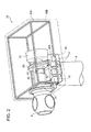
- Fig. 2 is an oblique perspective view of an exemplary configuration inside a nacelle of a wind turbine generator according to one embodiment.
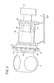
- Fig. 3 is a side view of a shafting of the wind turbine generator shown in Fig. 2 .
- Fig. 4 is a cross-sectional view of the shafting shown in Fig. 3 .
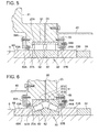
- Fig. 5 is an enlarged view of an area indicated by the reference "A" of Fig. 4 .
- Fig. 6 is an enlarged view of an area indicated by the reference "B" of Fig.4 .
- the wind turbine generator 1 includes a rotor 3 composed of at least one blade 2 and a hub 4, a rotation shaft 6 coupled to the hub 4, a generator 16 which generates electrical power, and a drive train 10 which transmits rotation energy of the rotation shaft 6 to the generator 16.
- various equipments including the rotation shaft 6 may be housed in a nacelle 30 which is disposed atop a tower 8 standing on the water or on the ground and may be covered by a nacelle cover 30B of the nacelle 30. Also, the hub 4 may be covered by a hub cover 5.
- the drive train 10 includes a hydraulic pump 12 attached to the rotation shaft 6, and a hydraulic motor 14 connected to the hydraulic pump 12 via a high pressure oil line 13 and a low pressure oil line 15.
- the hydraulic pump 12 is configured to be driven by the rotation shaft 6 and to pressurize a working oil so as to generate a high pressure working oil (pressurized oil).
- the outlet of the hydraulic pump 12 is connected to the inlet of the hydraulic motor 14 via the high pressure oil line 13.
- the pressurized oil generated in the hydraulic pump 12 is supplied to the hydraulic motor 14 via the high pressure oil line 13, so that the hydraulic motor 14 is driven by the pressurized oil.
- the low pressure working oil having performed work in the hydraulic motor 14 is returned again to the hydraulic pump 12 via the low pressure oil line 15 provided between the outlet of the hydraulic motor 14 and the inlet of the hydraulic pump 12.
- the output shaft of the hydraulic motor 14 is connected to the rotational shaft of the generator 16, so that rotation of the hydraulic motor 14 is inputted into the generator 16.
- the number of each of the hydraulic pump 12, the hydraulic motor 14 and the generator 16 is not necessarily limited, and may be one at the least.
- the drive train 10 and the generator 16 are disposed inside the nacelle 30.
- the nacelle 30 includes a nacelle base plate 30A which supports the bearing housing 21, 22 of each of the bearings 20, 22, a nacelle cover 30B which covers various equipments placed on the nacelle base plate 30A, and a nacelle frame 30C to which the nacelle cover 30B is fixed.
- the nacelle base plate 30A is formed of a cast steel such as a ductile cast iron or a high strength cast iron, for instance.
- the hydraulic pump 12 is attached to an end of the rotation shaft 6. Also, at both sides of the rotation shaft 6, a pair of equipment placement tables is provided respectively (however, only the equipment placement table 46 at the near side is shown in Fig. 2 ), and a pair of a hydraulic motors 14 and a generator 16 are disposed on each of the equipment placement tables 46.
- the equipment placement tables 46 are supported by the nacelle base plate 30A and the nacelle frame 30C attached thereto.
- the rotation shaft 6 is, as shown in Figs. 1 to 4 , supported rotatably to the nacelle 30 via the first bearing 20 and the second bearing 22.
- the first bearing 20 is positioned at the hub 4 side and the second bearing 22 is positioned farther from the hub 4 compared to the first bearing 20.
- the bearing housing 21, 23 of each of the bearings 20, 22 is supported by the nacelle base plate 30A of the nacelle 30, and also connected to each other by a connection member 40 of a cylindrical shape.
- connection member 40 may have a pair of cutouts 42 formed at both sides of the rotation shaft, respectively.
- the space formed by the cutout 42 can be used for a variety of purposes (for instance, suspension of components using a lift such as a crane).
- At least one brake caliper 27 is fixed directly or indirectly to the bearing housing 21 of the first bearing 20.
- the brake caliper 27 is configured to force a brake pad against a brake disc 28 which is fastened to the hub 4 with a flange of the rotation shaft 6, so as to apply braking force to the rotor 3 and the rotation shaft 6.
- the rotation shaft 6 has a smaller diameter in the area around the mounting position of the second bearing 22 (the second mounting position) compared to the diameter in the area around the mounting position of the first bearing 20 (the first mounting position). In other words, the rotation shaft 6 has a diameter which decreases from the area around the first mounting position toward the area around the second mounting position.
- the first bearing 20 is disposed closer to the hub 4 compared to the second bearing 22 and thus receives larger load. Therefore, by decreasing the diameter of the rotation shaft 6 from the area around the first mounting position toward the area around the second mounting position, it is possible to adopt the first bearing 20 of a larger size than the second bearing 22 and thus to improve durability of the first bearing 20. Also, as the rotation shaft 6 at the area around the second mounting position has a relatively small diameter, it is possible to reduce weight of the rotation shaft 6 and to reduce weight and size of the second bearing 22.
- a first stepped portion 6A is provided for restricting the inner race of the first bearing 20 from moving toward the hub 4.
- a second stepped portion 6B is provided for restricting the inner race of the second bearing 22 from moving toward the hub 4.
- the outer circumferential surface of the rotation shaft 6 is upraised so as to form the second stepped portion 6B, the diameter of the rotation shaft 6 slightly increasing at the upraised part.
- the diameter of the rotation shaft 6 at the upraised part is set smaller than the diameter of the inner race of the first bearing 20.
- the first bearing 20 includes an inner race 50 fit onto the outer circumference of the rotation shaft 6, an outer race 51 fit onto the inner circumference of the bearing housing 21, and a roller 52 provided between the inner race 50 and the outer race 51. All of the inner race 50, the outer race 51, and the bearing housing 21 have a ring shape continuous in the circumferential direction, which is a so-called seamless structure.
- the first bearing 20 is a cylindrical roller bearing (an example of a thrust free bearing) where the roller 52 formed of a cylindrical roller is fit into a groove provided on the outer race 51 so that the position of the roller 52 is restricted in the axial direction with respect to the outer race 51 but the roller 52 is movable in the axial direction with respect to the inner race 50.
- a pair of inner race fixing rings (53A, 53B) are provided, respectively. That is, the inner race 50 is disposed so as to be sandwiched between a first inner race fixing ring 53A positioned on the side closer to the hub 4 and a second inner race fixing ring 53B positioned on the side farther from the hub 4.
- the first inner race fixing ring 53A is fit onto the rotation shaft 6 so as to contact the first stepped portion 6A provided for the rotation shaft 6. Also, on the opposite side of the inner race 50 across the second inner race fixing ring 53B, a fixing nut 54 is disposed, the fixing nut 54 having a female thread which is configured to be screwed to a male thread formed on the outer circumference of the rotation shaft 6.
- the inner race 50 is forced against the side of the first inner race fixing ring 53A which is in contact with the first stepped portion 6A by the fastening force of the fixing nut 54 transmitted to the inner race 50 via the second inner race fixing ring 53B, so that the position of the inner race 50 is restricted in the axial direction.
- the fastening force by a shrink disc may be utilized for restricting the position of the inner race 50 in the axial direction, for instance.
- the outer race 51 of the first bearing 20 is sandwiched between: a projection 21A which projects inward in the radial direction from the bearing housing 21 along the outer circumferential surface of the rotation shaft 6; and an outer race fixing plate 55 attached to the bearing housing 21, so that the position of the outer race 51 is restricted in the axial direction.
- an inner flow path 24 is provided for supplying a lubricant oil to a rolling contact surface between the roller 52 and the inner race 50 or the outer race 51 of the first bearing 20.
- the inner flow path 24 runs through the outer race 51 and communicates with the annular space (where the roller 52 is disposed) between the inner race 50 and the outer race 51.
- the annular space is filled with the lubricant oil supplied via the inner flow path 24.
- a seal ring (56A, 56B) is provided for the purpose of preventing leakage of the lubricant oil from the annular space between the inner race 50 and the outer race 51.
- a seal ring 56A, and a spacer ring 57A adjacent to the seal ring 56A are inserted and held between the bearing housing 21 and the seal fixing plate 58A attached to the bearing housing 21.
- a seal ring 56B, and a spacer ring 57B adjacent to the seal ring 56B are inserted and held between an outer race fixing plate 55 and a seal fixing plate 58B attached to the outer race fixing plate 55.
- the spacer ring (57A, 57B) is provided for the purpose of recovering the sealability in a case where the inner race fixing ring (53A, 53B) has become worn by the contact with the seal ring (56A, 56B). That is, when the inner race fixing ring (53A, 53B) has become worn and the sealability has decreased, the positions of the seal ring (56A, 56B) and the spacer ring (57A, 57B) are reversed so that the seal ring (56A, 56B) contacts the inner race fixing ring (53A, 53B) at a different position, which enables recovering the sealability.
- the second bearing 22 includes an inner race 60 fit onto the outer circumference of the rotation shaft 6, an outer race 61 fit onto the inner circumference of the bearing housing 23, and a roller 62 provided between the inner race 60 and the outer race 61. All of the inner race 60, the outer race 61, and the bearing housing 23 have a ring shape continuous in the circumferential direction, which is a so-called seamless structure.
- the second bearing 22 is a taper roller bearing where the roller 62 is a tapered roller.
- the taper roller bearing is designed to receive axial load (thrust load) and thus is not a "thrust free bearing".
- a pair of inner race fixing rings (63A, 63B) is provided, respectively. That is, the inner race 60 is disposed so as to be sandwiched between a third inner race fixing ring 63A positioned on the side closer to the hub 4 and a fourth inner race fixing ring 63B positioned on the side farther from the hub 4.
- the third inner race fixing ring 63A is fit onto the rotation shaft 6 so as to contact the second stepped portion 6B provided for the rotation shaft 6. Also, on the opposite side of the inner race 60 across the fourth inner race fixing ring 63B, a fixing nut 64 is disposed, the fixing nut 64 having a female thread which is configured to be screwed to a male thread formed on the outer circumference of the rotation shaft 6.
- the inner race 60 is forced against the side of the third inner race fixing ring 63A which is in contact with the second stepped portion 6B by the fastening force of the fixing nut 64 transmitted to the inner race 60 via the fourth inner race fixing ring 63B, so that the position of the inner race 60 is restricted in the axial direction.
- the fastening force by a shrink disc may be utilized for restricting the position of the inner race 60 in the axial direction, for instance.
- the outer race 61 of the second bearing 22 is sandwiched between: a projection 23A which projects inward in the radial direction from the bearing housing 23 along the outer circumferential surface of the rotation shaft 6; and an outer race fixing plate 65 attached to the bearing housing 23, so that the position of the outer race 61 is restricted in the axial direction.
- the outer race 61 may be composed of a pair of annular pieces (61A, 61B) each of which has a cross section of a trapezoidal shape and an intermediate piece 61C provided between the annular pieces 61A, 61B.
- an inner flow path 26 is provided for supplying a lubricant oil to a rolling contact surface between the roller 62 and the inner race 60 or the outer race 61 of the second bearing 22.
- the inner flow path 26 runs through the outer race 61 and communicates with the annular space (where the roller 62 is disposed) between the inner race 60 and the outer race 61.
- the annular space is filled with the lubricant oil supplied via the inner flow path 26.
- a seal ring (66A, 66B) is provided for the purpose of preventing leakage of the lubricant oil from the annular space between the inner race 60 and the outer race 61.
- a seal ring 66A and a spacer ring 67A are inserted and held between the bearing housing 23 and the seal fixing plate 68A attached to the bearing housing 23.
- a seal ring 66B and a spacer ring 67B are inserted and held between an outer race fixing plate 65 and a seal fixing plate 68B attached to the outer race fixing plate 55.
- the spacer ring (67A, 67B) is provided for the purpose of recovering the sealability in a case where the inner race fixing ring (63A, 63B) has become worn by the contact with the seal ring (66A, 66B). That is, when the inner race fixing ring (63A, 63B) has become worn and the sealability has decreased, the positions of the seal ring (66A, 66B) and the spacer ring (67A, 67B) are reversed so that the seal ring (66A, 66B) contacts the inner race fixing ring (63A, 56B) at a different position, which enables recovering the sealability.
- the first bearing 20 and the second bearing 22 are mounted to the rotation shaft 6 in a state where the rotation shaft 6 is placed standing upright in the vertical direction.
- the outline of the shafting assembly method according to some embodiment will be described as follows.
- the first bearing (“the first bearing” described herein represents not only the first bearing 20 but the bearing unit as a whole including the bearing housing 21) is moved relative to the rotation shaft 6 to a first mounting position so that the rotation shaft 6 standing upright is inserted into the first bearing. Then, in the state where the first bearing is supported from below and held at the first mounting position, the first bearing is mounted to the rotation shaft 6. Further, in the state where the first bearing is held at the first mounting position, a lower end of a spacer (for instance, a spacer 70 shown in Figs. 8A to 8C ) is fixed to the first bearing so that the spacer extends upward from the first bearing.
- a spacer for instance, a spacer 70 shown in Figs. 8A to 8C
- the second bearing (the second bearing” described herein represents not only the second bearing 22 but the bearing unit as a whole including the bearing housing 23) is moved relative to the rotation shaft 6 to a second mounting position so that the rotation shaft 6 standing upright is inserted into the second bearing and the second bearing contacts an upper end of the spacer. After this, the second bearing is fixed to the upper end of the spacer. Finally, in the state where the second bearing is fixed to the upper end of the spacer, the second bearing is mounted to the rotation shaft 6 at the second mounting position.
- Figs. 7A to 7C are illustrations of the steps of mounting the first bearing to the rotation shaft according to one embodiment.
- Figs. 8A to 8C are illustrations of the steps of fixing the spacer to the first bearing according to one embodiment.
- Fig. 9 is an illustration of a socket-and-spigot joint between the spacer and the first bearing.
- Figs. 10A to 10C are illustrations of the steps of mounting the second bearing to the rotation shaft according to one embodiment.
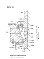
- Fig. 11 is an illustration of a socket-and-spigot joint between the spacer and the second bearing.
- the inner race 50 of the first bearing 20 is fit onto the outer circumference of the rotation shaft 6.
- the first inner race fixing ring 53A, the inner race 50, and the second inner race fixing ring 53B are fit around the rotation shaft 6 in this order, and then the fixing nut 54 is screwed to a male thread formed on the outer circumferential surface of the rotation shaft 6.
- the first inner race fixing ring 53A is fit onto the outer circumference of the rotation shaft 6 so as to contact the first stepped portion 6A provided for the outer circumferential surface of the rotation shaft 6.
- the inner race 50 is fit onto the outer circumference of the rotation shaft 6 so as to contact the inner race fixing ring 53A.
- the second inner race fixing ring 53B is fit onto the outer circumference of the rotation shaft 6 so as to contact the inner race 50 from the opposite side of the first inner race fixing ring 53A across the inner race 50.
- the fixing nut 54 is screwed to a male thread of the rotation shaft 6 so as to contact the second inner race fixing ring 53B from the opposite side of the inner race 50 across the second inner race fixing ring 53B.
- each of the inner race 50, the inner race fixing rings (53A, 53B) and the fixing nut 54 is moved to the respective attachment position by being lowered from the upper end toward the lower end of the rotation shaft 6 which is in the state of standing upright.
- a first bearing component assembly where the outer race 51 and the roller 52 are attached to the bearing housing 21 of the first bearing 20 is moved to the mounting position of the first bearing 20 to the rotation shaft 6 (the first mounting position) by being lowered along the rotation shaft 6 standing upright.
- the first bearing component assembly of the first bearing 20 (an assembly composed of the bearing housing 21, the outer race 51 and the roller 52) is held at the first mounting position by being supported from below.
- the outer race 51 of the first bearing component assembly is facing the inner race 50 fit onto the outer circumference of the rotation shaft 6.
- the outer race fixing plate 55, the seal ring (56A, 56B), the spacer ring (57A, 57B) and the seal fixing plate (58A, 58B) are attached to the first bearing component assembly. Accordingly, the mounting of the first bearing 20 to the rotation shaft 6 is completed.
- the first bearing 20 is a thrust free bearing
- the first bearing 20 is continuously held at the first mounting position by being supported from below until the mounting of the second bearing 22 to the rotation shaft 6 is completed and the rotation shaft 6 is returned to the substantially horizontal position.
- the bearing housing 21 upon holding the first bearing component assembly at the first mounting position, the bearing housing 21 is supported from below via a brake disc 28.
- the holding position where the first bearing component assembly is held may be adjusted by inserting an annular plate 29 between the brake disc 28 and the bearing housing 21, the annular plate 29 having a thickness which has been adjusted in advance.
- the lower end of the spacer 70 is fixed to the first bearing 20 which is mounted to the rotation shaft 6 so that the spacer 70 extends upward from the first bearing 20.
- the spacer 70 includes a first cylinder 72 positioned on the first bearing 20 side, a second cylinder 74 positioned on the second bearing 22 side, and an annular member 76 provided between the first cylinder 72 and the second cylinder 74.
- the first cylinder 72 is attached to the bearing housing 21 of the first bearing 20 held at the first mounting position by being supported from below, and then the annular member 76 and the second cylinder 74 are connected to the first cylinder 72.
- the spacer 70 is composed of the first cylinder 72, the second cylinder 74 and the annular member 76 for the purpose of easily performing removal of the spacer 70, as described below in reference to Figs. 13A to 13C .
- the lower end of the spacer 70 (the first cylinder 72) and the bearing housing 21 of the first bearing 20 are fit together at a socket-and-spigot joint 73. That is, a circular projection or recess formed on the lower end of the spacer 70 (the first cylinder 72) is fit into a circular recess or projection formed on the bearing housing 21.
- the position of the first bearing 20 is determined with respect to the spacer 70 in the radial direction of the rotation shaft 6.
- the bearing housing 23 of the second bearing 22 is moved downward along the rotation shaft 6 and fixed to the upper end of the spacer 70 (the second cylinder 74).
- the mounting position of the bearing housing 23 of the second bearing 22 to the rotation shaft 6 in the axial direction is determined at the second mounting position. That is, the length of the spacer 70 is set so that the mounting position of the second bearing 22 to the rotation shaft 6 in the axial direction is determined at the second mounting position. Accordingly, the second bearing 22 is mounted to the rotation shaft 6 at the second mounting position which is away from the first mounting position where the first bearing 20 is held by a distance corresponding to the length of the spacer 70.
- the third inner race fixing ring 63A positioned at the hub 4 side is fit in advance onto the outer circumference of the rotation shaft 6 so as to contact the stepped portion 6B provided on the outer circumferential surface of the rotation shaft 6. Also, among the pair of annular pieces (61A, 61B), a first piece 61A positioned at the first bearing 20 side is fit onto the inner circumference of the bearing housing 23.
- the upper end of the spacer 70 (the second cylinder 74) and the bearing housing 23 of the first bearing 22 are fit together at a socket-and-spigot joint 75. That is, a circular projection or recess formed on the upper end of the spacer 70 (the second cylinder 74) is fit into a circular recess or projection formed on the bearing housing 23.
- the position of the second bearing 22 is determined with respect to the spacer 70 in the radial direction of the rotation shaft 6.
- a second bearing component assembly composed of the inner race 60 and the roller 62 is fit onto the outer circumference of the rotation shaft 6 at the second mounting position, and the intermediate piece 61C is fit onto the bearing housing 23.
- a second piece 61B positioned at the farther side from the first bearing 20 is fit onto the bearing housing 23.
- a bearing 22 can be obtained where the roller 62 is provided between the inner race 60 and the outer race 61.
- the fourth inner race fixing rig 63B positioned on the side farther from the hub 4 among the inner race fixing rings (63A, 63B) is fit onto the outer circumference of the rotation shaft 6, and the fixing nut 64 is screwed to a male thread formed on the outer circumferential surface of the rotation shaft 6.
- the outer race fixing plate 65, the seal ring (66A, 66B), the spacer ring (67A, 67B), and the seal fixing plate (68A, 68B) are attached to the bearing housing 23.
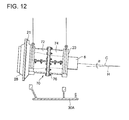
- Fig. 12 is an illustration of installation of the rotation shaft to the nacelle, where the first bearing and the second bearing are mounted to the rotation shaft.
- Figs. 13A to 13C are illustrations of the steps of removing the spacer from a pair of bearing housings.
- the rotation shaft 6 is mounted onto the nacelle base plate 30A.
- the rotation shaft 6 is lifted up by a lift along with the first bearing and the second bearing, and moved to above the nacelle base plate 30A. Then, the bearing housings 21, 23 are fixed to the nacelle base plate 30A.
- the space G (which corresponds to the thickness of the annular member 76) formed between the first cylinder 72 and the second cylinder 74 by removing the annular member 76 is set to be large enough to disconnect the socket-and-spigot joint 73, 75.
- the spacer 70 remains after the rotation shaft 6 is mounted to the nacelle base plate 30A, serving as a connection member of the first bearing 20 and the second bearing 22 during operation of the wind turbine generator 1.
- the connection member 40 shown in Figs. 3 and 4 may be used as the spacer 70.
- the first bearing 20 and the second bearing 22 are mounted in the state where the rotation shaft 6 is standing upright, it is possible to perform the bearing mounting work efficiently even with the rotation shaft 6 of a large diameter. Also, upon mounting the first bearing (thrust free bearing) 20 to the erect rotation shaft 6, by holding the first bearing 20 at the first mounting position by supporting from below, it is possible to accurately perform mounting of the first bearing 20 to the rotation shaft 6. Moreover, as the second bearing 22 is fixed to the upper end of the spacer 70 whose lower end is fixed to the first bearing 20 held at the first mounting position and then the second bearing 22 is mounted to the rotation shaft 6 at the second mounting position, the relative position of the second bearing 22 with respect to the first bearing 20 is accurately determined.
- connection member 40 the bearings 21, 23 may be connected by a connection frame instead of the connection member 40, or in addition to the connection member 40.
- Fig. 14 is an oblique perspective view of an interior structure of a nacelle of a wind turbine generator including a connection frame provided between a pair of bearing housings 21, 23.
- the connection frame 80 may include: a connection plate 82 which is provided above the rotation shaft 6 to connect the upper parts of the bearing housings 21, 23 with each other and has an attachment part 83 for a component lifting mechanism such as a crane; and a pair of supporting parts 84 which supports the connection plate 82 to the nacelle base plate 30A at both sides of the rotation shaft 6.
- connection plate 82 it is possible not only to contribute to maintaining the bearings 20, 22 concentric by connecting the upper parts of bearing housings 21, 23 with each other by the connection plate 82, but also to support the load of the component lifting mechanism by the supporting parts 84 in a case where the component lifting mechanism is attached to the attachment part 83 provided for the connection plate 82.
- the attachment part 83 may be configured so that a jib of a crane being the component lifting mechanism is fixable to the attachment part 83 using an arbitrary fastening member. Also, as shown in Fig. 14 , the supporting parts 84 may be configured to serve as stairs for workers to climb up and down.
Landscapes
- Engineering & Computer Science (AREA)
- General Engineering & Computer Science (AREA)
- Mechanical Engineering (AREA)
- Chemical & Material Sciences (AREA)
- Combustion & Propulsion (AREA)
- Life Sciences & Earth Sciences (AREA)
- Sustainable Energy (AREA)
- Sustainable Development (AREA)
- Power Engineering (AREA)
- General Life Sciences & Earth Sciences (AREA)
- Oceanography (AREA)
- Wind Motors (AREA)
- Mounting Of Bearings Or Others (AREA)
Abstract
Description
- The present disclosure relates to a shafting assembly method and a shafting assembly jig for a power generating apparatus of a renewable energy type. A power generating apparatus of a renewable energy type herein is a power generating apparatus utilizing a renewable energy such as wind, tidal current, ocean current, and river current. For instance, a wind turbine generator, a tidal current generator, an ocean current generator, or a river current generator can be named.
- Recently, from the perspective of preserving the global environment, a power generating apparatus of a renewable energy type which includes a wind turbine generator utilizing wind energy and a generator utilizing tidal current, ocean current or river current has become increasingly popular. There is known a power generating apparatus of a renewable energy type comprising: a blade which receives renewable energy; a hub to which the blade is attached; a rotation shaft coupled to the hub; and a generator which converts rotation energy of the rotation shaft to electrical power.
- A power generating apparatus of a renewable energy type has been growing in size from the perspective of improving power generation efficiency, and thus the load which acts on the rotation shaft tends to increase further. Therefore, there has been proposed a power generating apparatus of a renewable energy type which is configured to support the rotation shaft on the nacelle using a pair of bearings.
- For instance, in the wind turbine generators disclosed in Patent Documents 1 to 8, a rotation shaft is supported on a nacelle via a pair of bearings including a front bearing which is closer to a hub and a rear bearing which is farther from the hub. Also,
Patent Documents 6 to 9 disclose a configuration in which a bearing housing is provided integratedly for a front bearing and a second bearing. -
- [Patent Document 1]
US2011/0266806A - [Patent Document 2]
WO2009/080712A - [Patent Document 3]
WO2011/016108A - [Patent Document 4]
US2011/0143880A - [Patent Document 5]
TW201126062A - [Patent Document 6]
KR10-2011-0070623A - [Patent Document 7]
JP2009-19625A - [Patent Document 8]
EP1780409A - [Patent Document 9]
WO2007/119952A - In a case where a pair of bearing supports a rotation shaft, one of the bearings may be configured to receive thrust load while the other one of the bearings as a thrust free bearing receives radial load only.
- However, due to the structure of a thrust free bearing, bearing components such as a race and a roller are allowed to move in the axial direction, and thus the thrust free bearing is not positioned stably in the axial direction during mounting of the bearings to the rotation shaft, which makes it difficult to perform the shafting assembly accurately.
- In this regard, although Patent Documents 1 to 9 disclose a wind turbine generator where a rotation shaft is supported by a pair of bearings composed of a front bearing and a rear bearing, no solution is disclosed on how to improve the accuracy in the shafting assembly in a case where one of the bearings is a thrust free bearing.
- A purpose of at least one embodiment of the present invention is to provide a shafting assembly method and a shafting assembly jig for a power generating apparatus of a renewable energy type, whereby it is possible to improve the accuracy in the shafting assembly in a case where a rotation shaft is supported by a pair of bearings including a thrust free bearing.
- An assembly method according to one embodiment of the present invention is for a shafting of a power generating apparatus of a renewable energy type which includes:
- at least one blade;
- a hub to which the at least one blade is attached;
- a rotation shaft coupled to the hub; and
- a first bearing and a second bearing which support the rotation shaft, and the method comprises:
- a step of placing the rotation shaft to stand upright along a vertical direction;
- a step of moving the first bearing relative to the rotation shaft to a first mounting position so that the rotation shaft standing upright is inserted into the first bearing which is a thrust free bearing;
- a step of holding the first bearing at the first mounting position by supporting the first bearing from below;
- a step of mounting the first bearing to the rotation shaft in a state where the first bearing is held at the first mounting position;
- a step of fixing a lower end of a spacer to the first bearing so that the spacer extends upward from the first bearing in a state where the first bearing is held at the first mounting position;
- a step of moving the second bearing relative to the rotation shaft to a second mounting position so that the rotation shaft standing upright is inserted into the second bearing and the second bearing contacts an upper end of the spacer;
- a step of fixing the second bearing to the upper end of the spacer; and
- a step of mounting the second bearing to the rotation shaft in a state where the second bearing is fixed to the upper end of the spacer.
- Hereinafter, "thrust free bearing" cited in this specification includes a slide bearing or a roller bearing of any type which allows sliding in a determined range in the axial direction between a roller and a race, or between a race and a shaft or a bearing housing.
- According to the above shafting assembly method, as the first bearing and the second bearing are mounted in a state where the rotation shaft is standing upright, it is possible to perform the bearing mounting work efficiently even with a rotation shaft of a large diameter. Also, when mounting the first bearing (thrust free bearing) to the erect rotation shaft, as the first bearing is held at the first mounting position by being supported from below, it is possible to mount the first bearing to the rotation shaft accurately. Moreover, as the second bearing is fixed to the upper end of the spacer whose lower end is fixed to the first bearing held at the first mounting position and then the second bearing is mounted to the rotation shaft at the second mounting position, the relative position of the second bearing with respect to the first bearing is accurately determined.
- In some embodiment, a brake disc is attached to a lower end part of the rotation shaft standing upright, a brake pad being forced against the brake disc by a brake caliper which is fixed to a bearing housing of the first bearing; and in the step of holding the first bearing, the bearing housing of the first bearing is supported from below via the brake disc.
- As a result, by supporting the bearing housing of the first bearing from below using a brake disc, it is possible to hold the first bearing at the first mounting position.
- In some embodiment, in the step of fixing the lower end of the spacer to the first bearing, the first bearing is positioned with respect to the spacer in a radial direction of the rotation shaft by a socket-and-spigot joint; and in the step of fixing the second bearing to the upper end of the spacer, the second bearing is positioned with respect to the spacer in the radial direction of the rotation shaft by a socket-and-spigot joint.
- When the centers of the first bearing and the second bearing supporting the rotation shaft are misaligned, load component in an unexpected direction acts on the bearings, thus raising the possibility of drastic decrease of the bearing lifetime. In this regard, by positioning each of the first bearing and the second bearing with respect to the spacer in the radial direction of the rotation shaft by the socket-and-spigot joint with the spacer, it is possible to perform alignment of the first bearing and the second bearing and thus to prevent the drastic decrease of the bearing lifetime caused by misalignment of the centers of the first bearing and the second bearing.
- In some embodiments, the spacer includes a first cylinder disposed at a first bearing side, a second cylinder disposed at a second bearing side, and an annular member provided between the first cylinder and the second cylinder, and the method further comprises:
- a step of mounting the rotation shaft to a nacelle of the power generating apparatus of a renewable energy type along with the first bearing and the second bearing which are connected by the spacer; and
- after the step of mounting the rotation shaft, a step of removing the spacer from the first bearing and the second bearing by: removing the annular member from the first cylinder and the second cylinder; moving the first cylinder and the second cylinder in directions away from the first bearing and the second bearing along the rotation shaft, respectively; and then disconnecting the socket-and-spigot joint between the first cylinder and the first bearing and between the second cylinder and the second bearing.
- As a result, by mounting the rotation shaft onto a nacelle along with the first bearing and the second bearing in a state where the first bearing and the second bearing are connected to each other by the spacer, it is possible to maintain the first bearing and the second bearing concentric with each other by the socket-and-spigot joint with the spacer even after mounting the rotation shaft onto the nacelle. Also, by adopting a spacer including a first cylinder, a second cylinder and an annular member, it is possible to disconnect the socket-and-spigot joint between the first cylinder and the first bearing and between the second cylinder and the second bearing, and thus to easily remove the spacer even after mounting the rotation shaft onto the nacelle.
- In some embodiment, each of the first cylinder and the second cylinder includes a pair of half shells, and
in the step of removing the spacer, the pair of half shells of each of the first cylinder and the second cylinder is separated from each other in a state where the socket-and-spigot joint of each of the first cylinder and the second cylinder has been disconnected. - As a result, by separating each of the first cylinder and the second cylinder into half shells after the socket-and-spigot joint has been disconnected, it is even easier to remove the spacer.
- In some embodiments, in the step of mounting the first bearing to the rotation shaft, an inner race of the first bearing is fit onto an outer circumferential surface of the rotation shaft at the first mounting position, and in the step of holding the first bearing, a first bearing component assembly where an outer race and a roller are attached to the bearing housing of the first bearing is supported from below and the first bearing component assembly is held around the inner race at the first mounting position. Also, a first stepped portion is provided at the first mounting position of the rotation shaft, and, in the step of mounting the first bearing to the rotation shaft, a first inner race fixing ring is fit onto the outer circumferential surface of the rotation shaft so as to contact the first stepped portion, the inner race is fit onto the outer circumferential surface of the rotation shaft so as to contact the first inner race fixing ring, a second inner race fixing ring is fit onto the outer circumferential surface of the rotation shaft so as to contact the inner race from an opposite side of the first inner race fixing ring across the inner race, and then a fixing nut is screwed to a thread formed on the outer circumferential surface of the rotation shaft so as to contact the second inner race fixing ring from an opposite side of the inner race across the second inner race fixing ring.
- As a result, it is possible to easily mount the first bearing to the rotation shaft at the first mounting position.
- Also, in the step of mounting the first bearing to the rotation shaft, a first seal ring may be disposed around the first inner race fixing ring to be attached to the bearing housing of the first bearing, and also a second seal ring may be disposed around the second inner race fixing ring to be attached to the bearing housing of the first bearing.
- In some embodiment, the second bearing is a taper roller bearing which includes an inner race, a roller, an outer race formed of at least one pair of annular pieces, and a bearing housing,
in the step of fixing the second bearing to the upper end of the spacer, the bearing housing of the second bearing is fixed to the upper end of the spacer, and
in the step of mounting the second bearing to the rotation shaft, a first piece positioned on a first bearing side among the at least one pair of annular pieces of the outer race is attached to the bearing housing, a second bearing component assembly formed of the roller and the inner race is fit onto an outer circumferential surface of the rotation shaft at the second mounting position, and a second piece positioned on a side farther from the first bearing among the at least one pair of annular pieces of the outer race is attached to the bearing housing. Also, a second stepped portion is provided at the second mounting position of the rotation shaft, and
in the step of mounting the second bearing to the rotation shaft, a third inner race fixing ring is fit onto the outer circumferential surface of the rotation shaft so as to contact the second stepped portion, the second bearing component assembly is fit onto the outer circumferential surface of the rotation shaft so that the inner race contacts the third inner race fixing ring, a fourth inner race fixing ring is fit onto the outer circumferential surface of the rotation shaft so as to contact the inner race from an opposite side of the third inner race fixing ring across the second bearing component assembly, and a fixing nut is screwed to a thread formed on the outer circumferential surface of the rotation shaft so as to contact the fourth inner race fixing ring from an opposite side of the second bearing component assembly across the fourth inner race fixing ring. - As a result, it is possible to easily mount the second bearing to the rotation shaft at the second mounting position.
- In the step of mounting the second bearing to the rotation shaft, a third seal ring may be disposed around the third inner race fixing ring to be attached to the bearing housing of the second bearing, and also a fourth seal ring may be disposed around the fourth inner race fixing ring to be attached to the bearing housing of the second bearing.
- In some embodiment, the spacer remains after mounting the rotation shaft to a nacelle of the power generating apparatus of a renewable energy type, the spacer serving as a connection member between the first bearing and the second bearing while the power generating apparatus of a renewable energy type is operated.
- As a result, the first bearing and the second bearing are connected to each other by the spacer, and the bearing housing of each of the bearings is bound by the spacer. Therefore, even if a complex load and moment from the renewable energy source is inputted into the rotation shaft during operation of the power generating apparatus of a renewable energy type, it is possible to maintain the bearings concentric with each other by the function of the spacer.
- In some embodiment, the spacer has a cylindrical shape which surrounds the rotation shaft mounted on the nacelle and a pair of cutouts is formed on the spacer at both sides of the rotation shaft, respectively.
- As a result, even in a case where the spacer remains as a connection member after the rotation shaft is mounted onto the nacelle, it is possible to utilize the space formed by the cutout on the spacer for a variety of purposes (for instance, suspension of components using a lift such as a crane).
- In some embodiment, the assembly method for the shafting further comprises a step of lifting the rotation shaft together with the first bearing and the second bearing by a lift and mounting the rotation shaft to a nacelle of the power generating apparatus of a renewable energy type in a state where the first bearing and the second bearing are connected with each other by the spacer.
- The rotation shaft is usually mounted to the nacelle inclining so that a predetermined angle (tilt angle) is formed with respect to the horizontal direction. In this case, upon mounting the rotation shaft to the nacelle, lifting up the rotation shaft by a lift (a crane, for instance) using an eyebolt and the like provided for the bearing housing causes component force to act on the first bearing (thrust free bearing) in the axial direction of the rotation shaft corresponding to the tilt angle, raising the possibility that the first bearing moves or get damaged. In this regard, by performing the lifting of the rotation shaft in the state where the first bearing and the second bearing are connected to each other by the spacer as described above, it is possible to prevent misalignment of or damage to the first bearing.
- In some embodiment, the assembly method of the shafting further comprises, after the step of mounting the rotation shaft to the nacelle, a step of connecting an upper part of the bearing housing of the first bearing and an upper part of the bearing housing of the second bearing by a connection frame.
- As a result, the bearing housing of the first bearing and the bearing housing of the second bearing are connected to each other by the connection frame, and the bearing housing of each of the bearings is bound by the connection frame. Therefore, even if a complex load and moment from the renewable energy source is inputted into the rotation shaft during operation of the power generating apparatus of a renewable energy type, it is possible to maintain the bearings concentric by the function of the connection frame.
- In the bearing housing of each of the first bearing and the second bearing, an inner flow path may be formed for supplying a lubricant oil to a rolling surface or a sliding surface of said each of the first bearing and the second bearing.
- A shafting assembly jig according to at least one embodiment of the present invention is used for a shafting of a power generating apparatus of a renewable energy type which includes at least one blade, a hub to which the at least one blade is attached, a rotation shaft coupled to the hub, and a first bearing and a second bearing which support the rotation shaft, the shafting assembly jig being provided for mounting the first bearing and the second bearing to the rotation shaft while the first bearing which is a thrust free bearing is supported from below in a state where the rotation shaft is placed standing upright in a vertical direction, and the shafting assembly jig comprises:
- a lower end configured to be fixed to the first bearing which is held at the first mounting position by being supported from below around the rotation shaft standing upright, and
- an upper end to which the second bearing is fixable at the second mounting position at an opposite side of the first bearing across the shafting assembly jig, in a state where the first bearing is held at the first mounting position.
- According to the above shafting assembly jig, it is possible to fix the second bearing to the upper end of the shafting assembly jig whose lower end is fixed to the first bearing (thrust free bearing) which is held at the first mounting position, and to mount the second bearing to the rotation shaft at the second mounting position. Therefore, upon mounting the first bearing and the second bearing to the rotation shaft in the state of standing upright, it is possible to accurately determine the relative position of the second bearing with respect to the first bearing.
- In some embodiment, the first bearing is positioned with respect to the shafting assembly jig in a radial direction of the rotation shaft by a socket-and-spigot joint between the lower end and the first bearing, and the second bearing is positioned with respect to the shafting assembly jig in the radial direction of the rotation shaft by a socket-and-spigot joint between the upper end and the second bearing.
- As a result, by positioning each of the first bearing and the second bearing in the radial direction of the rotation shaft with respect to the shafting assembly jig, it is possible to perform alignment of the first bearing and the second bearing, and thus to prevent drastic decrease of the bearing lifetime caused by misalignment of the centers of the first bearing and the second bearing.
- In some embodiment, the shafting assembly jig further comprises: a first cylinder which is positioned on a first bearing side and forms the lower end; a second cylinder which is positioned on a second bearing side and forms the upper end; and an annular member provided removably between the first cylinder and the second cylinder.
- As a result, in the state where the first bearing and the second bearing are mounted to the rotation shaft, it is possible to disconnect the socket-and-spigot joint between first bearing and the spacer and between the second bearing and the spacer, and thus to easily remove the spacer.
- Further, each of the first cylinder and the second cylinder may include a pair of half shells which can be divided.
- As a result, by dividing the first cylinder and the second cylinder into half shells after disconnecting the socket-and-spigot joint, it is even easier to remove the spacer.
- According to at least one embodiment of the present invention, as the first bearing and the second bearing are mounted in the state where the rotation shaft is standing upright, it is possible to perform the bearing mounting work efficiently even with a rotation shaft of a large diameter. Also, upon mounting the first bearing (thrust free bearing) to the erect rotation shaft, by holding the first bearing at the first mounting position by supporting from below, it is possible to accurately mount the first bearing to the rotation shaft. Moreover, as the second bearing is fixed to the upper end of the spacer whose lower end is fixed to the first bearing held at the first mounting position and then the second bearing is mounted to the rotation shaft at the second mounting position, the relative position of the second bearing with respect to the first bearing is accurately determined.
-
-
Fig. 1 is schematic view of an overall configuration of a wind turbine generator according to one embodiment. -
Fig. 2 is an oblique perspective view of an exemplary configuration inside a nacelle of a wind turbine generator according to one embodiment. -
Fig. 3 is a side view of a shafting of the wind turbine generator shown inFig. 2 . -
Fig. 4 is a cross-sectional view of the shafting shown inFig. 3 . -
Fig. 5 is an enlarged view of an area indicated by reference "A" inFig. 4 . -
Fig. 6 is an enlarged view of an area indicated by reference "B" inFig. 4 . -
Figs. 7A to 7C are illustrations of the steps of mounting the first bearing to the rotation shaft according to one embodiment. -
Figs. 8A to 8C are illustrations of the steps of fixing the spacer to the first bearing according to one embodiment. -
Fig. 9 is an illustration of a socket-and-spigot joint between the spacer and the first bearing. -
Figs. 10A to 10C are illustrations of the steps of mounting the second bearing to the rotation shaft according to one embodiment. -
Fig. 11 is an illustration of a socket-and-spigot joint between the spacer and the second bearing. -
Fig. 12 is an illustration of installation of the rotation shaft to the nacelle, where the first bearing and the second bearing are mounted to the rotation shaft. -
Figs. 13A to 13C are illustrations of the steps of removing the spacer from a pair of bearing housings. -
Fig. 14 is an oblique perspective view of an interior structure of a nacelle of a wind turbine generator including a connection frame provided between a pair of bearing housings. - Embodiments of the present invention will now be described in detail with reference to the accompanying drawings. It is intended, however, that unless particularly specified, dimensions, materials, shapes, relative positions and the like of components described in the embodiments shall be interpreted as illustrative only and not limitative of the scope of the present invention.
- Hereinafter, a power generating apparatus of a renewable energy type which is an object of the shafting assembly method according to one embodiment of the present invention will be described, and then, the shafting assembly method will be described.
- While a wind turbine generator is described as an example of a power generating apparatus of a renewable energy type, the shafting assembly method according to the embodiment of the present invention can be applied to other power generating apparatuses of a renewable energy type such as a tidal current generator, an ocean current generator, and a river current generator.
-
Fig. 1 is schematic view of an overall configuration of a wind turbine generator according to one embodiment.Fig. 2 is an oblique perspective view of an exemplary configuration inside a nacelle of a wind turbine generator according to one embodiment.Fig. 3 is a side view of a shafting of the wind turbine generator shown inFig. 2 .Fig. 4 is a cross-sectional view of the shafting shown inFig. 3 .Fig. 5 is an enlarged view of an area indicated by the reference "A" ofFig. 4 .Fig. 6 is an enlarged view of an area indicated by the reference "B" ofFig.4 . - As shown in
Fig. 1 , the wind turbine generator 1 includes arotor 3 composed of at least oneblade 2 and ahub 4, arotation shaft 6 coupled to thehub 4, agenerator 16 which generates electrical power, and adrive train 10 which transmits rotation energy of therotation shaft 6 to thegenerator 16. - Herein, various equipments including the
rotation shaft 6 may be housed in anacelle 30 which is disposed atop atower 8 standing on the water or on the ground and may be covered by anacelle cover 30B of thenacelle 30. Also, thehub 4 may be covered by ahub cover 5. - In some embodiment, as shown in
Fig. 1 , thedrive train 10 includes ahydraulic pump 12 attached to therotation shaft 6, and ahydraulic motor 14 connected to thehydraulic pump 12 via a highpressure oil line 13 and a lowpressure oil line 15. Thehydraulic pump 12 is configured to be driven by therotation shaft 6 and to pressurize a working oil so as to generate a high pressure working oil (pressurized oil). The outlet of thehydraulic pump 12 is connected to the inlet of thehydraulic motor 14 via the highpressure oil line 13. Thus, the pressurized oil generated in thehydraulic pump 12 is supplied to thehydraulic motor 14 via the highpressure oil line 13, so that thehydraulic motor 14 is driven by the pressurized oil. The low pressure working oil having performed work in thehydraulic motor 14 is returned again to thehydraulic pump 12 via the lowpressure oil line 15 provided between the outlet of thehydraulic motor 14 and the inlet of thehydraulic pump 12. The output shaft of thehydraulic motor 14 is connected to the rotational shaft of thegenerator 16, so that rotation of thehydraulic motor 14 is inputted into thegenerator 16. - Herein, the number of each of the
hydraulic pump 12, thehydraulic motor 14 and thegenerator 16 is not necessarily limited, and may be one at the least. - In one embodiment, the
drive train 10 and thegenerator 16 are disposed inside thenacelle 30. - In the exemplary embodiment shown in
Fig. 2 , thenacelle 30 includes anacelle base plate 30A which supports the bearinghousing bearings nacelle cover 30B which covers various equipments placed on thenacelle base plate 30A, and anacelle frame 30C to which thenacelle cover 30B is fixed. Thenacelle base plate 30A is formed of a cast steel such as a ductile cast iron or a high strength cast iron, for instance. - The
hydraulic pump 12 is attached to an end of therotation shaft 6. Also, at both sides of therotation shaft 6, a pair of equipment placement tables is provided respectively (however, only the equipment placement table 46 at the near side is shown inFig. 2 ), and a pair of ahydraulic motors 14 and agenerator 16 are disposed on each of the equipment placement tables 46. The equipment placement tables 46 are supported by thenacelle base plate 30A and thenacelle frame 30C attached thereto. - The
rotation shaft 6 is, as shown inFigs. 1 to 4 , supported rotatably to thenacelle 30 via thefirst bearing 20 and thesecond bearing 22. Thefirst bearing 20 is positioned at thehub 4 side and thesecond bearing 22 is positioned farther from thehub 4 compared to thefirst bearing 20. In some embodiment, the bearinghousing bearings nacelle base plate 30A of thenacelle 30, and also connected to each other by aconnection member 40 of a cylindrical shape. - The
connection member 40 may have a pair ofcutouts 42 formed at both sides of the rotation shaft, respectively. The space formed by thecutout 42 can be used for a variety of purposes (for instance, suspension of components using a lift such as a crane). - Further, at least one
brake caliper 27 is fixed directly or indirectly to the bearinghousing 21 of thefirst bearing 20. Thebrake caliper 27 is configured to force a brake pad against abrake disc 28 which is fastened to thehub 4 with a flange of therotation shaft 6, so as to apply braking force to therotor 3 and therotation shaft 6. - In one embodiment, as shown in
Figs. 3 and4 , therotation shaft 6 has a smaller diameter in the area around the mounting position of the second bearing 22 (the second mounting position) compared to the diameter in the area around the mounting position of the first bearing 20 (the first mounting position). In other words, therotation shaft 6 has a diameter which decreases from the area around the first mounting position toward the area around the second mounting position. - In a case where the
rotation shaft 6 is supported by a pair of thebearings first bearing 20 is disposed closer to thehub 4 compared to thesecond bearing 22 and thus receives larger load. Therefore, by decreasing the diameter of therotation shaft 6 from the area around the first mounting position toward the area around the second mounting position, it is possible to adopt thefirst bearing 20 of a larger size than thesecond bearing 22 and thus to improve durability of thefirst bearing 20. Also, as therotation shaft 6 at the area around the second mounting position has a relatively small diameter, it is possible to reduce weight of therotation shaft 6 and to reduce weight and size of thesecond bearing 22. - Further, in the area around the first mounting position, a first stepped
portion 6A is provided for restricting the inner race of thefirst bearing 20 from moving toward thehub 4. Similarly, in the area around the second mounting position, a second steppedportion 6B is provided for restricting the inner race of thesecond bearing 22 from moving toward thehub 4. - Also, the outer circumferential surface of the
rotation shaft 6 is upraised so as to form the second steppedportion 6B, the diameter of therotation shaft 6 slightly increasing at the upraised part. The diameter of therotation shaft 6 at the upraised part is set smaller than the diameter of the inner race of thefirst bearing 20. As a result, it is possible to adopt the shafting assembly method in which thefirst bearing 20 and thesecond bearing 20 are fit around therotation shaft 6 in this order from the end of therotation shaft 6 at the farther side from thehub 4. - In some embodiment, as shown in
Fig. 5 , thefirst bearing 20 includes aninner race 50 fit onto the outer circumference of therotation shaft 6, anouter race 51 fit onto the inner circumference of the bearinghousing 21, and aroller 52 provided between theinner race 50 and theouter race 51. All of theinner race 50, theouter race 51, and the bearinghousing 21 have a ring shape continuous in the circumferential direction, which is a so-called seamless structure. - In the exemplary embodiment shown in
Fig. 5 , thefirst bearing 20 is a cylindrical roller bearing (an example of a thrust free bearing) where theroller 52 formed of a cylindrical roller is fit into a groove provided on theouter race 51 so that the position of theroller 52 is restricted in the axial direction with respect to theouter race 51 but theroller 52 is movable in the axial direction with respect to theinner race 50. - Further, in the exemplary embodiment shown in
Fig. 5 , at both sides of theinner race 50 of thefirst bearing 20, a pair of inner race fixing rings (53A, 53B) are provided, respectively. That is, theinner race 50 is disposed so as to be sandwiched between a first innerrace fixing ring 53A positioned on the side closer to thehub 4 and a second innerrace fixing ring 53B positioned on the side farther from thehub 4. - The first inner
race fixing ring 53A is fit onto therotation shaft 6 so as to contact the first steppedportion 6A provided for therotation shaft 6. Also, on the opposite side of theinner race 50 across the second innerrace fixing ring 53B, a fixingnut 54 is disposed, the fixingnut 54 having a female thread which is configured to be screwed to a male thread formed on the outer circumference of therotation shaft 6. Thus, theinner race 50 is forced against the side of the first innerrace fixing ring 53A which is in contact with the first steppedportion 6A by the fastening force of the fixingnut 54 transmitted to theinner race 50 via the second innerrace fixing ring 53B, so that the position of theinner race 50 is restricted in the axial direction. Also, instead of the fastening force by the fixingnut 54, the fastening force by a shrink disc may be utilized for restricting the position of theinner race 50 in the axial direction, for instance. - On the other hand, the
outer race 51 of thefirst bearing 20 is sandwiched between: aprojection 21A which projects inward in the radial direction from the bearinghousing 21 along the outer circumferential surface of therotation shaft 6; and an outerrace fixing plate 55 attached to the bearinghousing 21, so that the position of theouter race 51 is restricted in the axial direction. - In the bearing
housing 21 of thefirst bearing 20, aninner flow path 24 is provided for supplying a lubricant oil to a rolling contact surface between theroller 52 and theinner race 50 or theouter race 51 of thefirst bearing 20. Theinner flow path 24 runs through theouter race 51 and communicates with the annular space (where theroller 52 is disposed) between theinner race 50 and theouter race 51. The annular space is filled with the lubricant oil supplied via theinner flow path 24. In some embodiment, for the purpose of preventing leakage of the lubricant oil from the annular space between theinner race 50 and theouter race 51, a seal ring (56A, 56B) is provided. In the exemplary embodiment shown inFig. 5 , aseal ring 56A, and aspacer ring 57A adjacent to theseal ring 56A are inserted and held between the bearinghousing 21 and theseal fixing plate 58A attached to the bearinghousing 21. On the other hand, aseal ring 56B, and aspacer ring 57B adjacent to theseal ring 56B are inserted and held between an outerrace fixing plate 55 and aseal fixing plate 58B attached to the outerrace fixing plate 55. - Herein, the spacer ring (57A, 57B) is provided for the purpose of recovering the sealability in a case where the inner race fixing ring (53A, 53B) has become worn by the contact with the seal ring (56A, 56B). That is, when the inner race fixing ring (53A, 53B) has become worn and the sealability has decreased, the positions of the seal ring (56A, 56B) and the spacer ring (57A, 57B) are reversed so that the seal ring (56A, 56B) contacts the inner race fixing ring (53A, 53B) at a different position, which enables recovering the sealability.
- In some embodiment, as shown in
Fig. 6 , thesecond bearing 22 includes aninner race 60 fit onto the outer circumference of therotation shaft 6, anouter race 61 fit onto the inner circumference of the bearinghousing 23, and aroller 62 provided between theinner race 60 and theouter race 61. All of theinner race 60, theouter race 61, and the bearinghousing 23 have a ring shape continuous in the circumferential direction, which is a so-called seamless structure. - In the exemplary embodiment shown in
Fig. 6 , thesecond bearing 22 is a taper roller bearing where theroller 62 is a tapered roller. The taper roller bearing is designed to receive axial load (thrust load) and thus is not a "thrust free bearing". - Further, in the exemplary embodiment shown in
Fig. 6 , at both sides of theinner race 60 of thesecond bearing 22, a pair of inner race fixing rings (63A, 63B) is provided, respectively. That is, theinner race 60 is disposed so as to be sandwiched between a third innerrace fixing ring 63A positioned on the side closer to thehub 4 and a fourth innerrace fixing ring 63B positioned on the side farther from thehub 4. - The third inner
race fixing ring 63A is fit onto therotation shaft 6 so as to contact the second steppedportion 6B provided for therotation shaft 6. Also, on the opposite side of theinner race 60 across the fourth innerrace fixing ring 63B, a fixingnut 64 is disposed, the fixingnut 64 having a female thread which is configured to be screwed to a male thread formed on the outer circumference of therotation shaft 6. Thus, theinner race 60 is forced against the side of the third innerrace fixing ring 63A which is in contact with the second steppedportion 6B by the fastening force of the fixingnut 64 transmitted to theinner race 60 via the fourth innerrace fixing ring 63B, so that the position of theinner race 60 is restricted in the axial direction. Also, instead of the fastening force by the fixingnut 64, the fastening force by a shrink disc may be utilized for restricting the position of theinner race 60 in the axial direction, for instance. - On the other hand, the
outer race 61 of thesecond bearing 22 is sandwiched between: aprojection 23A which projects inward in the radial direction from the bearinghousing 23 along the outer circumferential surface of therotation shaft 6; and an outerrace fixing plate 65 attached to the bearinghousing 23, so that the position of theouter race 61 is restricted in the axial direction. Theouter race 61 may be composed of a pair of annular pieces (61A, 61B) each of which has a cross section of a trapezoidal shape and anintermediate piece 61C provided between theannular pieces - In the bearing
housing 23 of thesecond bearing 22, aninner flow path 26 is provided for supplying a lubricant oil to a rolling contact surface between theroller 62 and theinner race 60 or theouter race 61 of thesecond bearing 22. Theinner flow path 26 runs through theouter race 61 and communicates with the annular space (where theroller 62 is disposed) between theinner race 60 and theouter race 61. The annular space is filled with the lubricant oil supplied via theinner flow path 26. - In some embodiment, for the purpose of preventing leakage of the lubricant oil from the annular space between the
inner race 60 and theouter race 61, a seal ring (66A, 66B) is provided. In the exemplary embodiment shown inFig. 6 , aseal ring 66A and aspacer ring 67A are inserted and held between the bearinghousing 23 and theseal fixing plate 68A attached to the bearinghousing 23. On the other hand, aseal ring 66B and aspacer ring 67B are inserted and held between an outerrace fixing plate 65 and aseal fixing plate 68B attached to the outerrace fixing plate 55. - Herein, the spacer ring (67A, 67B) is provided for the purpose of recovering the sealability in a case where the inner race fixing ring (63A, 63B) has become worn by the contact with the seal ring (66A, 66B). That is, when the inner race fixing ring (63A, 63B) has become worn and the sealability has decreased, the positions of the seal ring (66A, 66B) and the spacer ring (67A, 67B) are reversed so that the seal ring (66A, 66B) contacts the inner race fixing ring (63A, 56B) at a different position, which enables recovering the sealability.
- In some embodiment, when assembling the above shafting, the
first bearing 20 and thesecond bearing 22 are mounted to therotation shaft 6 in a state where therotation shaft 6 is placed standing upright in the vertical direction. The outline of the shafting assembly method according to some embodiment will be described as follows. - The first bearing ("the first bearing" described herein represents not only the
first bearing 20 but the bearing unit as a whole including the bearing housing 21) is moved relative to therotation shaft 6 to a first mounting position so that therotation shaft 6 standing upright is inserted into the first bearing. Then, in the state where the first bearing is supported from below and held at the first mounting position, the first bearing is mounted to therotation shaft 6. Further, in the state where the first bearing is held at the first mounting position, a lower end of a spacer (for instance, aspacer 70 shown inFigs. 8A to 8C ) is fixed to the first bearing so that the spacer extends upward from the first bearing. Subsequently, the second bearing ("the second bearing" described herein represents not only thesecond bearing 22 but the bearing unit as a whole including the bearing housing 23) is moved relative to therotation shaft 6 to a second mounting position so that therotation shaft 6 standing upright is inserted into the second bearing and the second bearing contacts an upper end of the spacer. After this, the second bearing is fixed to the upper end of the spacer. Finally, in the state where the second bearing is fixed to the upper end of the spacer, the second bearing is mounted to therotation shaft 6 at the second mounting position. - The shafting assembly method according to one embodiment will be described below in detail.
Figs. 7A to 7C are illustrations of the steps of mounting the first bearing to the rotation shaft according to one embodiment.Figs. 8A to 8C are illustrations of the steps of fixing the spacer to the first bearing according to one embodiment.Fig. 9 is an illustration of a socket-and-spigot joint between the spacer and the first bearing.Figs. 10A to 10C are illustrations of the steps of mounting the second bearing to the rotation shaft according to one embodiment.Fig. 11 is an illustration of a socket-and-spigot joint between the spacer and the second bearing. - First, as shown in
Fig. 7A , in the state where therotation shaft 6 is stood upright, theinner race 50 of thefirst bearing 20 is fit onto the outer circumference of therotation shaft 6. In some embodiment, the first innerrace fixing ring 53A, theinner race 50, and the second innerrace fixing ring 53B are fit around therotation shaft 6 in this order, and then the fixingnut 54 is screwed to a male thread formed on the outer circumferential surface of therotation shaft 6. - Specifically, firstly, the first inner
race fixing ring 53A is fit onto the outer circumference of therotation shaft 6 so as to contact the first steppedportion 6A provided for the outer circumferential surface of therotation shaft 6. After this, theinner race 50 is fit onto the outer circumference of therotation shaft 6 so as to contact the innerrace fixing ring 53A. Then, the second innerrace fixing ring 53B is fit onto the outer circumference of therotation shaft 6 so as to contact theinner race 50 from the opposite side of the first innerrace fixing ring 53A across theinner race 50. Finally, the fixingnut 54 is screwed to a male thread of therotation shaft 6 so as to contact the second innerrace fixing ring 53B from the opposite side of theinner race 50 across the second innerrace fixing ring 53B. Herein, each of theinner race 50, the inner race fixing rings (53A, 53B) and the fixingnut 54 is moved to the respective attachment position by being lowered from the upper end toward the lower end of therotation shaft 6 which is in the state of standing upright. - Next, as shown in
Fig. 7B , a first bearing component assembly where theouter race 51 and theroller 52 are attached to the bearinghousing 21 of thefirst bearing 20 is moved to the mounting position of thefirst bearing 20 to the rotation shaft 6 (the first mounting position) by being lowered along therotation shaft 6 standing upright. - Then, as shown in
Fig. 7C , the first bearing component assembly of the first bearing 20 (an assembly composed of the bearinghousing 21, theouter race 51 and the roller 52) is held at the first mounting position by being supported from below. At the first mounting position, theouter race 51 of the first bearing component assembly is facing theinner race 50 fit onto the outer circumference of therotation shaft 6. In some embodiment, in the state where the first bearing component assembly is held at the first mounting position, the outerrace fixing plate 55, the seal ring (56A, 56B), the spacer ring (57A, 57B) and the seal fixing plate (58A, 58B) are attached to the first bearing component assembly. Accordingly, the mounting of thefirst bearing 20 to therotation shaft 6 is completed. - As the
first bearing 20 is a thrust free bearing, thefirst bearing 20 is continuously held at the first mounting position by being supported from below until the mounting of thesecond bearing 22 to therotation shaft 6 is completed and therotation shaft 6 is returned to the substantially horizontal position. - Also, in some embodiment, as shown in
Fig. 7C , upon holding the first bearing component assembly at the first mounting position, the bearinghousing 21 is supported from below via abrake disc 28. Herein, the holding position where the first bearing component assembly is held may be adjusted by inserting anannular plate 29 between thebrake disc 28 and the bearinghousing 21, theannular plate 29 having a thickness which has been adjusted in advance. - Next, the lower end of the
spacer 70 is fixed to thefirst bearing 20 which is mounted to therotation shaft 6 so that thespacer 70 extends upward from thefirst bearing 20. - In some embodiment, as shown in
Fig. 8C , thespacer 70 includes afirst cylinder 72 positioned on thefirst bearing 20 side, asecond cylinder 74 positioned on thesecond bearing 22 side, and anannular member 76 provided between thefirst cylinder 72 and thesecond cylinder 74. In this case, as shown inFigs. 8A to 8C , thefirst cylinder 72 is attached to the bearinghousing 21 of thefirst bearing 20 held at the first mounting position by being supported from below, and then theannular member 76 and thesecond cylinder 74 are connected to thefirst cylinder 72. Herein, thespacer 70 is composed of thefirst cylinder 72, thesecond cylinder 74 and theannular member 76 for the purpose of easily performing removal of thespacer 70, as described below in reference toFigs. 13A to 13C . - In one embodiment, as shown in
Fig. 9 , upon fixing the lower end of the spacer 70 (the first cylinder 72) to thefirst bearing 20, the lower end of the spacer 70 (the first cylinder 72) and the bearinghousing 21 of thefirst bearing 20 are fit together at a socket-and-spigot joint 73. That is, a circular projection or recess formed on the lower end of the spacer 70 (the first cylinder 72) is fit into a circular recess or projection formed on the bearinghousing 21. As a result, the position of thefirst bearing 20 is determined with respect to thespacer 70 in the radial direction of therotation shaft 6. - Subsequently, as shown in
Fig. 10A , in the state where therotation shaft 6 is stood upright, the bearinghousing 23 of thesecond bearing 22 is moved downward along therotation shaft 6 and fixed to the upper end of the spacer 70 (the second cylinder 74). As a result, the mounting position of the bearinghousing 23 of thesecond bearing 22 to therotation shaft 6 in the axial direction is determined at the second mounting position. That is, the length of thespacer 70 is set so that the mounting position of thesecond bearing 22 to therotation shaft 6 in the axial direction is determined at the second mounting position. Accordingly, thesecond bearing 22 is mounted to therotation shaft 6 at the second mounting position which is away from the first mounting position where thefirst bearing 20 is held by a distance corresponding to the length of thespacer 70. - Among the inner race fixing rings (63A, 63B), the third inner
race fixing ring 63A positioned at thehub 4 side is fit in advance onto the outer circumference of therotation shaft 6 so as to contact the steppedportion 6B provided on the outer circumferential surface of therotation shaft 6. Also, among the pair of annular pieces (61A, 61B), afirst piece 61A positioned at thefirst bearing 20 side is fit onto the inner circumference of the bearinghousing 23. - In one embodiment, as shown in
Fig. 11 , upon fixing the bearinghousing 23 of thesecond bearing 22 to the upper end of the spacer 70 (the second cylinder 74), the upper end of the spacer 70 (the second cylinder 74) and the bearinghousing 23 of thefirst bearing 22 are fit together at a socket-and-spigot joint 75. That is, a circular projection or recess formed on the upper end of the spacer 70 (the second cylinder 74) is fit into a circular recess or projection formed on the bearinghousing 23. As a result, the position of thesecond bearing 22 is determined with respect to thespacer 70 in the radial direction of therotation shaft 6. - As described above, by determining the position of each of the
first bearing 20 and thesecond bearing 22 in the radial direction with respect to thespacer 70 by the socket-and-spigot joint (73, 75) with thespacer 70, it is possible to perform alignment of thefirst bearing 20 and thesecond bearing 22. - Further, as shown in
Fig. 10B , a second bearing component assembly composed of theinner race 60 and theroller 62 is fit onto the outer circumference of therotation shaft 6 at the second mounting position, and theintermediate piece 61C is fit onto the bearinghousing 23. After this, among the annular pieces (61A, 61B), asecond piece 61B positioned at the farther side from thefirst bearing 20 is fit onto the bearinghousing 23. As a result, abearing 22 can be obtained where theroller 62 is provided between theinner race 60 and theouter race 61. - Also, for restricting the position of the
inner race 60 in the axial direction, the fourth innerrace fixing rig 63B positioned on the side farther from thehub 4 among the inner race fixing rings (63A, 63B) is fit onto the outer circumference of therotation shaft 6, and the fixingnut 64 is screwed to a male thread formed on the outer circumferential surface of therotation shaft 6. - Then, the outer
race fixing plate 65, the seal ring (66A, 66B), the spacer ring (67A, 67B), and the seal fixing plate (68A, 68B) are attached to the bearinghousing 23. - Accordingly, as shown in
Fig. 10C , the mounting of thesecond bearing 22 to therotation shaft 6 at the second mounting position is completed. After this, therotation shaft 6 to which thefirst bearing 20 and thesecond bearing 22 are mounted is returned to the substantially horizontal position. Herein, as thesecond bearing 22 is designed to receive the thrust load, it is not necessary to support thefirst bearing 20 from below after thesecond bearing 22 is mounted to therotation shaft 6. - Next, the method of installing the
rotation shaft 6 to thenacelle 30 after having attached thefirst bearing 20 and thesecond bearing 22 to therotation shaft 6 will be described. -
Fig. 12 is an illustration of installation of the rotation shaft to the nacelle, where the first bearing and the second bearing are mounted to the rotation shaft.Figs. 13A to 13C are illustrations of the steps of removing the spacer from a pair of bearing housings. - In some embodiment, along with the first bearing and the second bearing ("the first bearing" and "the second bearing" herein do not only represent the
first bearing 20 and thesecond bearing 22 but also the bearing units as a whole including the bearinghousings 21, 23) connected to each other by thespacer 70, therotation shaft 6 is mounted onto thenacelle base plate 30A. At this time, as shown inFig. 12 , in the state where the bearinghousings spacer 70, therotation shaft 6 is lifted up by a lift along with the first bearing and the second bearing, and moved to above thenacelle base plate 30A. Then, the bearinghousings nacelle base plate 30A. - Upon lifting the
rotation shaft 6 up using a lift, an angle corresponding to a tilt angle "α" is formed between the center line C of therotation shaft 6 and the horizontal line H. Thus, the component force in the axial direction of therotation shaft 6 corresponding to the tilt angle "α" acts on the first bearing (thrust free bearing) 20, which raises the possibility that thefirst bearing 20 moves or get damaged. In this regard, by lifting up therotation shaft 6 in a state where thefirst bearing 20 and thesecond bearing 22 are connected to each other by thespacer 70 as described above, it is possible to prevent misalignment of or damage to thefirst bearing 20. - In one embodiment, as shown in
Figs. 13A to 13C , after mounting therotation shaft 6 to thenacelle base plate 30A, thespacer 70 which has been connecting the bearinghousing 21 of thefirst bearing 20 and the bearinghousing 23 of thesecond bearing 22 is removed. - Specifically, as shown in
Fig. 13A , anannular member 76 provided between thefirst cylinder 72 and thesecond cylinder 74 is removed and then thefirst cylinder 72 and thesecond cylinder 74 are moved along therotation shaft 6 in the directions (see the arrows in the drawing) away from thefirst bearing 20 and thesecond bearing 22, respectively. As a result, the socket-and-spigot joint 73 (seeFig. 9 ) between thefirst cylinder 72 and the bearinghousing 21 and the socket-and-spigot joint 75 (seeFig. 11 ) between thesecond cylinder 74 and the bearinghousing 23 are disconnected. After this, as shown inFig. 13B , a pair ofhalf shells first cylinder 72 is separated from each other, and a pair ofhalf shells second cylinder 74 is separated from each other. As a result, as shown inFig. 13C , therotation shaft 6 which has been covered by thespacer 70 is exposed. - Herein, the space G (which corresponds to the thickness of the annular member 76) formed between the
first cylinder 72 and thesecond cylinder 74 by removing theannular member 76 is set to be large enough to disconnect the socket-and-spigot joint - In another embodiment, the
spacer 70 remains after therotation shaft 6 is mounted to thenacelle base plate 30A, serving as a connection member of thefirst bearing 20 and thesecond bearing 22 during operation of the wind turbine generator 1. In this case, instead of the configuration including thefirst cylinder 72, thesecond cylinder 74 and theannular member 76, theconnection member 40 shown inFigs. 3 and4 may be used as thespacer 70. - As described above, according to the above embodiment, as the
first bearing 20 and thesecond bearing 22 are mounted in the state where therotation shaft 6 is standing upright, it is possible to perform the bearing mounting work efficiently even with therotation shaft 6 of a large diameter. Also, upon mounting the first bearing (thrust free bearing) 20 to theerect rotation shaft 6, by holding thefirst bearing 20 at the first mounting position by supporting from below, it is possible to accurately perform mounting of thefirst bearing 20 to therotation shaft 6. Moreover, as thesecond bearing 22 is fixed to the upper end of thespacer 70 whose lower end is fixed to thefirst bearing 20 held at the first mounting position and then thesecond bearing 22 is mounted to therotation shaft 6 at the second mounting position, the relative position of thesecond bearing 22 with respect to thefirst bearing 20 is accurately determined. - Embodiments of the present invention were described in detail above, but the present invention is not limited thereto, and various amendments and modifications may be implemented within a scope of the present invention.
- For instance, while the bearing
housing 21 of thefirst bearing 20 and the bearinghousing 23 of thesecond bearing 22 are connected by theconnection member 40, thebearings connection member 40, or in addition to theconnection member 40. -
Fig. 14 is an oblique perspective view of an interior structure of a nacelle of a wind turbine generator including a connection frame provided between a pair of bearinghousings connection frame 80 may include: aconnection plate 82 which is provided above therotation shaft 6 to connect the upper parts of the bearinghousings attachment part 83 for a component lifting mechanism such as a crane; and a pair of supporting parts 84 which supports theconnection plate 82 to thenacelle base plate 30A at both sides of therotation shaft 6. As a result, it is possible not only to contribute to maintaining thebearings housings connection plate 82, but also to support the load of the component lifting mechanism by the supporting parts 84 in a case where the component lifting mechanism is attached to theattachment part 83 provided for theconnection plate 82. - The
attachment part 83 may be configured so that a jib of a crane being the component lifting mechanism is fixable to theattachment part 83 using an arbitrary fastening member. Also, as shown inFig. 14 , the supporting parts 84 may be configured to serve as stairs for workers to climb up and down. -
- 1
- Wind turbine generator
- 2
- Blade
- 3
- Rotor
- 4
- Hub
- 5
- Hub cover
- 6
- Rotation shaft
- 6A
- First stepped portion
- 6B
- Second stepped portion
- 8
- Tower
- 10
- Drive train
- 12
- Hydraulic pump
- 13
- High pressure oil line
- 14
- Hydraulic motor
- 15
- Low pressure oil line
- 16
- Generator
- 20
- First bearing
- 21
- Bearing housing
- 22
- Second bearing
- 23
- Bearing housing
- 24
- Inner flow path
- 26
- Inner flow path
- 27
- Brake caliper
- 28
- Brake disc
- 30
- Nacelle
- 30A
- Nacelle base plate
- 30B
- Nacelle cover
- 30C
- Nacelle frame
- 40
- Connection member
- 42
- Cutout
- 46
- Equipment placement table
- 50
- Inner race
- 51
- Outer race
- 52
- Roller
- 53A
- First inner race fixing ring
- 53B
- Second inner race fixing ring
- 54
- Fixing nut
- 55
- Outer race fixing plate
- 56A, 56B
- Seal ring
- 57A, 57B
- Spacer ring
- 58A, 58B
- Seal fixing plate
- 60
- Inner race
- 61
- Outer race
- 62
- Roller
- 63A
- Third inner race fixing ring
- 63B
- Fourth inner race fixing ring
- 64
- Fixing ring
- 65
- Outer race fixing plate
- 66A, 66B
- Seal ring
- 67A, 67B
- Spacer ring
- 68A, 68B
- Seal fixing ring
- 70
- Spacer
- 72
- First cylinder
- 73
- Socket-and-spigot joint
- 74
- Second cylinder
- 75
- Socket-and-spigot joint
- 76
- Annular member
- 80
- Connection frame
- 82
- Connection plate
- 84
- Supporting part
Claims (20)
- An assembly method for a shafting of a power generating apparatus of a renewable energy type, the power generating apparatus of a renewable energy type including:at least one blade;a hub to which the at least one blade is attached;a rotation shaft coupled to the hub; anda first bearing and a second bearing which support the rotation shaft, the method comprising:a step of placing the rotation shaft to stand upright along a vertical direction;a step of moving the first bearing relative to the rotation shaft to a first mounting position so that the rotation shaft standing upright is inserted into the first bearing which is a thrust free bearing;a step of holding the first bearing at the first mounting position by supporting the first bearing from below;a step of mounting the first bearing to the rotation shaft in a state where the first bearing is held at the first mounting position;a step of fixing a lower end of a spacer to the first bearing so that the spacer extends upward from the first bearing in a state where the first bearing is held at the first mounting position;a step of moving the second bearing relative to the rotation shaft to a second mounting position so that the rotation shaft standing upright is inserted into the second bearing and the second bearing contacts an upper end of the spacer;a step of fixing the second bearing to the upper end of the spacer; anda step of mounting the second bearing to the rotation shaft in a state where the second bearing is fixed to the upper end of the spacer.
- The assembly method for a shafting of a power generating apparatus of a renewable energy type according to claim 1,
wherein a brake disc is attached to a lower end part of the rotation shaft standing upright, a brake pad being forced against the brake disc by a brake caliper which is fixed to a bearing housing of the first bearing; and
wherein, in the step of holding the first bearing, the bearing housing of the first bearing is supported from below via the brake disc. - The assembly method for a shafting of a power generating apparatus of a renewable energy type according to claim 1,
wherein, in the step of fixing the lower end of the spacer to the first bearing, the first bearing is positioned with respect to the spacer in a radial direction of the rotation shaft by a socket-and-spigot joint; and
wherein, in the step of fixing the second bearing to the upper end of the spacer, the second bearing is positioned with respect to the spacer in the radial direction of the rotation shaft by a socket-and-spigot joint. - The assembly method for a shafting of a power generating apparatus of a renewable energy type according to claim 3,
wherein the spacer includes a first cylinder disposed at a first bearing side, a second cylinder disposed at a second bearing side, and an annular member provided between the first cylinder and the second cylinder,
the method further comprising:a step of mounting the rotation shaft to a nacelle of the power generating apparatus of a renewable energy type together with the first bearing and the second bearing which are connected by the spacer; andafter the step of mounting the rotation shaft, a step of removing the spacer from the first bearing and the second bearing by: removing the annular member from the first cylinder and the second cylinder; moving the first cylinder and the second cylinder in directions away from the first bearing and the second bearing along the rotation shaft,respectively; and then disconnecting the socket-and-spigot joint between the first cylinder and the first bearing and between the second cylinder and the second bearing. - The assembly method for a shafting of a power generating apparatus of a renewable energy type according to claim 4,
wherein each of the first cylinder and the second cylinder includes a pair of half shells, and
wherein, in the step of removing the spacer, the pair of half shells of each of the first cylinder and the second cylinder is separated from each other in a state where the socket-and-spigot joint of each of the first cylinder and the second cylinder has been disconnected. - The assembly method for a shafting of a power generating apparatus of a renewable energy type according to claim 1,
wherein, in the step of mounting the first bearing to the rotation shaft, an inner race of the first bearing is fit onto an outer circumferential surface of the rotation shaft at the first mounting position, and
wherein, in the step of holding the first bearing, a first bearing component assembly where an outer race and a roller are attached to a bearing housing of the first bearing is supported from below and the first bearing component assembly is held around the inner race at the first mounting position. - The assembly method for a shafting of a power generating apparatus of a renewable energy type according to claim 6,
wherein a first stepped portion is provided at the first mounting position of the rotation shaft, and
wherein, in the step of mounting the first bearing to the rotation shaft, a first inner race fixing ring is fit onto the outer circumferential surface of the rotation shaft so as to contact the first stepped portion, the inner race is fit onto the outer circumferential surface of the rotation shaft so as to contact the first inner race fixing ring, a second inner race fixing ring is fit onto the outer circumferential surface of the rotation shaft so as to contact the inner race from an opposite side of the first inner race fixing ring across the inner race, and then a fixing nut is screwed to a thread formed on the outer circumferential surface of the rotation shaft so as to contact the second inner race fixing ring from an opposite side of the inner race across the second inner race fixing ring. - The assembly method for a shafting of a power generating apparatus of a renewable energy type according to claim 7,
wherein, in the step of mounting the first bearing to the rotation shaft, a first seal ring is disposed around the first inner race fixing ring and attached to the bearing housing of the first bearing, while a second seal ring is disposed around the second inner race fixing ring and attached to the bearing housing of the first bearing. - The assembly method for a shafting of a power generating apparatus of a renewable energy type according to claim 1,
wherein the second bearing is a taper roller bearing which includes an inner race, a roller, an outer race formed of at least one pair of annular pieces, and a bearing housing,
wherein, in the step of fixing the second bearing to the upper end of the spacer, the bearing housing of the second bearing is fixed to the upper end of the spacer, and wherein, in the step of mounting the second bearing to the rotation shaft, a first piece positioned on a first bearing side among the at least one pair of annular pieces of the outer race is attached to the bearing housing, a second bearing component assembly formed of the roller and the inner race is fit onto an outer circumferential surface of the rotation shaft at the second mounting position, and a second piece positioned on a side further from the first bearing among the at least one pair of annular pieces of the outer race is attached to the bearing housing. - The assembly method for a shafting of a power generating apparatus of a renewable energy type according to claim 9,
wherein a second stepped portion is provided at the second mounting position of the rotation shaft, and
wherein, in the step of mounting the second bearing to the rotation shaft, a third inner race fixing ring is fit onto the outer circumferential surface of the rotation shaft so as to contact the second stepped portion, the second bearing component assembly is fit onto the outer circumferential surface of the rotation shaft so that the inner race contacts the third inner race fixing ring, a fourth inner race fixing ring is fit onto the outer circumferential surface of the rotation shaft so as to contact the inner race from an opposite side of the third inner race fixing ring across the second bearing component assembly, and a fixing nut is screwed to a thread formed on the outer circumferential surface of the rotation shaft so as to contact the fourth inner race fixing ring from an opposite side of the second bearing component assembly across the fourth inner race fixing ring. - The assembly method for a shafting of a power generating apparatus of a renewable energy type according to claim 10,
wherein, in the step of mounting the second bearing to the rotation shaft, a third seal ring is disposed around the third inner race fixing ring and attached to the bearing housing of the second bearing, while a fourth seal ring is disposed around the fourth inner race fixing ring and attached to the bearing housing of the second bearing. - The assembly method for a shafting of a power generating apparatus of a renewable energy type according to claim 1,
wherein, the spacer remains after mounting the rotation shaft to a nacelle of the power generating apparatus of a renewable energy type, the spacer serving as a connection member between the first bearing and the second bearing while the power generating apparatus of a renewable energy type is operated. - The assembly method for a shafting of a power generating apparatus of a renewable energy type according to claim 12,
wherein the spacer has a cylindrical shape which surrounds the rotation shaft mounted on the nacelle and a pair of cutouts is formed on the spacer at both sides of the rotation shaft, respectively. - The assembly method for a shafting of a power generating apparatus of a renewable energy type according to claim 1, further comprising:a step of lifting the rotation shaft together with the first bearing and the second bearing by a lift and mounting the rotation shaft to a nacelle of the power generating apparatus of a renewable energy type in a state where the first bearing and the second bearing are connected with each other by the spacer.
- The assembly method for a shafting of a power generating apparatus of a renewable energy type according to claim 13, further comprising:after the step of mounting the rotation shaft to the nacelle, a step of connecting an upper part of the bearing housing of the first bearing and an upper part of the bearing housing of the second bearing by a connection frame.
- The assembly method for a shafting of a power generating apparatus of a renewable energy type according to claim 1,
wherein, in the bearing housing of each of the first bearing and the second bearing, an inner flow path is formed for supplying a lubricant oil to a rolling surface or a sliding surface of said each of the first bearing and the second bearing. - A shafting assembly jig for assembling a shafting of a power generating apparatus of a renewable energy type, the power generating apparatus including at least one blade, a hub to which the at least one blade is attached, a rotation shaft coupled to the hub, and a first bearing and a second bearing which support the rotation shaft, the shafting assembly jig being provided for mounting the first bearing and the second bearing to the rotation shaft while the first bearing which is a thrust free bearing is supported from below in a state where the rotation shaft is placed standing upright in a vertical direction, the shafting assembly jig comprising:a lower end configured to be fixed to the first bearing which is held at the first mounting position by being supported from below around the rotation shaft standing upright, andan upper end to which the second bearing is fixable at the second mounting position at an opposite side of the first bearing across the shafting assembly jig, in a state where the first bearing is held at the first mounting position.
- A shafting assembly jig for a power generating apparatus of a renewable energy type according to claim 17,
wherein the first bearing is positioned with respect to the shafting assembly jig in a radial direction of the rotation shaft by a socket-and-spigot joint between the lower end and the first bearing, and
wherein the second bearing is positioned with respect to the shafting assembly jig in the radial direction of the rotation shaft by a socket-and-spigot joint between the upper end and the second bearing. - A shafting assembly jig for a power generating apparatus of a renewable energy type according to claim 18, further comprising:a first cylinder which is positioned on a first bearing side and forms the lower end;a second cylinder which is positioned on a second bearing side and forms the upper end; andan annular member provided removably between the first cylinder and the second cylinder.
- An assembly jig for a shafting of a power generating apparatus of a renewable energy type according to claim 19,
wherein each of the first cylinder and the second cylinder includes a pair of half shells which can be divided.
Applications Claiming Priority (2)
| Application Number | Priority Date | Filing Date | Title |
|---|---|---|---|
| PCT/JP2012/004218 WO2013042294A1 (en) | 2011-09-22 | 2012-06-29 | A power generating apparatus of renewable energy type |
| PCT/JP2012/073590 WO2014002296A1 (en) | 2012-06-29 | 2012-09-14 | Method for assembling shafting of regenerated energy power generation device, and tool for assembling shafting |
Publications (3)
| Publication Number | Publication Date |
|---|---|
| EP2754893A1 true EP2754893A1 (en) | 2014-07-16 |
| EP2754893A4 EP2754893A4 (en) | 2015-12-09 |
| EP2754893B1 EP2754893B1 (en) | 2016-07-20 |
Family
ID=49784144
Family Applications (2)
| Application Number | Title | Priority Date | Filing Date |
|---|---|---|---|
| EP12880049.7A Not-in-force EP2754893B1 (en) | 2012-06-29 | 2012-09-14 | Method for assembling shafting of regenerated energy power generation device, and tool for assembling shafting |
| EP12879819.6A Not-in-force EP2754892B1 (en) | 2012-06-29 | 2012-09-14 | Method for assembling shafting of regenerated energy power generation device, and tool for assembling shafting |
Family Applications After (1)
| Application Number | Title | Priority Date | Filing Date |
|---|---|---|---|
| EP12879819.6A Not-in-force EP2754892B1 (en) | 2012-06-29 | 2012-09-14 | Method for assembling shafting of regenerated energy power generation device, and tool for assembling shafting |
Country Status (2)
| Country | Link |
|---|---|
| EP (2) | EP2754893B1 (en) |
| WO (3) | WO2014002297A1 (en) |
Cited By (15)
| Publication number | Priority date | Publication date | Assignee | Title |
|---|---|---|---|---|
| EP3279471A1 (en) * | 2016-08-03 | 2018-02-07 | Siemens Aktiengesellschaft | Wind turbine, bearing housing and method for operating a wind turbine |
| WO2018153418A1 (en) * | 2017-02-21 | 2018-08-30 | Vestas Wind Systems A/S | Wind turbine main rotor arrangement having means to prevent angular creep of outer bearing ring |
| US20190017552A1 (en) * | 2017-07-11 | 2019-01-17 | General Electric Company | Clamping apparatus for positioning a main bearing of a wind turbine during an installation and/or repair procedure |
| WO2019156720A1 (en) * | 2018-02-07 | 2019-08-15 | The Timken Company | Roller seating device for tapered roller bearings |
| CN110966149A (en) * | 2018-10-01 | 2020-04-07 | 西门子歌美飒可再生能源公司 | Bearing device for wind turbine, wind turbine and method of manufacture |
| EP3690239A1 (en) * | 2019-01-30 | 2020-08-05 | Siemens Gamesa Renewable Energy Innovation & Technology, S.L. | Bearing arrangement for a wind turbine and wind turbine |
| CN112879231A (en) * | 2019-11-29 | 2021-06-01 | 西门子歌美飒可再生能源创新与技术有限公司 | Method for assembling a drive train with improved stiffness for an electric machine |
| EP3904669A1 (en) * | 2020-04-28 | 2021-11-03 | Siemens Gamesa Renewable Energy A/S | Wind turbine |
| AT524464A1 (en) * | 2020-11-30 | 2022-06-15 | Miba Gleitlager Austria Gmbh | Method for assembling a rotor bearing of a wind turbine |
| WO2022194319A1 (en) * | 2021-03-18 | 2022-09-22 | Schaeffler Technologies AG & Co. KG | Main bearing assembly for a wind turbine |
| US11927176B2 (en) * | 2019-09-16 | 2024-03-12 | Siemens Gamesa Renewable Energy A/S | Bearing arrangement for a wind turbine and wind turbine |
| US12049873B2 (en) | 2020-01-08 | 2024-07-30 | Vestas Wind Systems A/S | Main bearing housing of a wind turbine |
| US12098709B2 (en) | 2020-11-30 | 2024-09-24 | Miba Gleitlager Austria Gmbh | Method for assembling a rotor bearing of a wind turbine |
| US12104580B2 (en) | 2020-01-08 | 2024-10-01 | Vestas Wind Systems A/S | Main bearing housing of a wind turbine |
| EP4737716A1 (en) * | 2024-10-30 | 2026-05-06 | ZF Friedrichshafen AG | Bearing arrangement for a wind turbine |
Families Citing this family (15)
| Publication number | Priority date | Publication date | Assignee | Title |
|---|---|---|---|---|
| DK177934B9 (en) | 2013-06-19 | 2015-01-19 | Envision Energy Denmark Aps | Assembly method for a main rotor shaft and an installation tool thereto |
| JP6448114B2 (en) * | 2013-07-23 | 2019-01-09 | 大洋プラント株式会社 | Wind energy equipment |
| EP2921728A1 (en) * | 2014-03-20 | 2015-09-23 | Areva Wind GmbH | Hybrid shaft bearing with a hydrodynamic bearing and a rolling bearing, wind generator comprising a hybrid shaft bearing, use of the hybrid shaft bearing and method of operating the hybrid shaft bearing |
| JP6644571B2 (en) * | 2016-02-08 | 2020-02-12 | 株式会社駒井ハルテック | How to install a nacelle on top of the tower |
| JP6351659B2 (en) * | 2016-05-20 | 2018-07-04 | 三菱重工業株式会社 | Wind turbine nacelle, wind turbine generator, and method for lifting components of wind turbine generator |
| CN106523290A (en) * | 2016-10-26 | 2017-03-22 | 国电联合动力技术有限公司 | Installing tool and method for wind generation set main bearing |
| DE102017128949A1 (en) * | 2017-12-06 | 2019-06-06 | Thyssenkrupp Ag | Rolling bearing assembly and method |
| CN108327921B (en) * | 2017-12-29 | 2023-12-26 | 北京华信宇航科技有限公司 | Nacelle with replaceable spherical cabin |
| CN108119305B (en) * | 2018-01-29 | 2024-01-26 | 湘潭大学 | A direct-drive yaw device for small and medium-sized wind turbines |
| WO2019155322A1 (en) * | 2018-02-08 | 2019-08-15 | Suzlon Energy Ltd. | Sealing arrangement for a main bearing of a wind turbine, bearing arrangement and wind turbine |
| ES2970617T3 (en) | 2018-04-12 | 2024-05-29 | Vestas Wind Sys As | Wind turbine drive train component with low friction radial shaft seal |
| DE102018120806A1 (en) * | 2018-08-27 | 2020-02-27 | Renk Aktiengesellschaft | Bearing arrangement of a rotor of a wind turbine |
| EP3857054B1 (en) | 2018-09-24 | 2024-05-22 | Vestas Wind Systems A/S | A wind turbine nacelle structure and a method of assembling a wind turbine nacelle structure |
| CN117662389B (en) * | 2022-08-31 | 2024-08-30 | 北京金风慧能技术有限公司 | Method for improving transmission power, transmission system assembly and wind generating set |
| EP4339456A1 (en) * | 2022-09-19 | 2024-03-20 | Nordex Energy SE & Co. KG | Support structure for a wind turbine and wind turbine |
Family Cites Families (27)
| Publication number | Priority date | Publication date | Assignee | Title |
|---|---|---|---|---|
| DK9500262U4 (en) | 1995-07-07 | 1996-10-07 | Bonus Energy As | Bottom frame for wind turbine housing and wind turbine comprising the same |
| JP2004092755A (en) * | 2002-08-30 | 2004-03-25 | Nsk Ltd | Method of assembling bearing device and bearing device |
| JP2006046107A (en) | 2004-08-02 | 2006-02-16 | Yanmar Co Ltd | Wind power generator |
| EP1945946A1 (en) * | 2005-10-31 | 2008-07-23 | Chapdrive As | A turbine driven electric power production system and a method for control thereof |
| JP4101844B2 (en) * | 2006-03-29 | 2008-06-18 | Ntn株式会社 | Bearing built-in jig, tapered roller bearing, method of assembling tapered roller bearing and main shaft support structure of wind power generator |
| KR100703564B1 (en) | 2006-04-14 | 2007-04-09 | 유니슨 주식회사 | Rotor for wind generator and its assembly method |
| DE102006027543A1 (en) * | 2006-06-14 | 2007-12-20 | Nordex Energy Gmbh | Wind turbine with a rotor |
| EP2014917B1 (en) | 2007-07-10 | 2017-08-30 | Siemens Aktiengesellschaft | Minimising wind turbine generator air gap with a specific shaft bearing arrangement |
| US8197215B2 (en) | 2007-12-21 | 2012-06-12 | Vestas Wind Systems A/S | Drive train for a wind turbine |
| DE102008013728A1 (en) * | 2008-03-11 | 2009-09-17 | Kenersys Gmbh | Wind energy plant for generating electrical energy |
| ES2563312T3 (en) | 2008-04-30 | 2016-03-14 | Multibrid Gmbh | Fairing of a gondola of a wind power installation |
| DK2143936T3 (en) * | 2008-07-07 | 2016-03-21 | Siemens Ag | Wind turbine comprising a main bearing, and method for the replacement of the main bearing |
| DE102008052412A1 (en) * | 2008-10-21 | 2010-04-22 | Aerodyn Energiesysteme Gmbh | Bearing housing for the storage of the rotor shaft of a wind turbine |
| DK2376797T3 (en) * | 2008-12-15 | 2016-08-22 | Jochen Corts | Segmented composite bearings and wind generator that uses hydraulic pump / motor combination |
| US8021101B2 (en) | 2008-12-15 | 2011-09-20 | General Electric Company | Wind turbine and method of assembling the same |
| EP2463510A1 (en) | 2009-08-03 | 2012-06-13 | Mitsubishi Heavy Industries, Ltd. | Wind driven generator and method of assembling same |
| EP2494198B1 (en) | 2009-10-27 | 2015-03-18 | Vestas Wind Systems A/S | A wind turbine and a mounting method thereof |
| EP2317137B1 (en) | 2009-11-02 | 2012-07-25 | General Electric Company | Configuration of a wind turbine nacelle |
| KR101138363B1 (en) | 2009-12-18 | 2012-04-26 | 삼성중공업 주식회사 | Shaft assembly for wind power ganeration and wind power ganeration including the same |
| TW201126062A (en) | 2010-01-29 | 2011-08-01 | Mitsubishi Heavy Ind Ltd | Wind power generator |
| KR101354328B1 (en) * | 2010-02-23 | 2014-01-22 | 아르테미스 인텔리전트 파워 리미티드 | Variable displacement radial piston fluid working machine |
| US20130011272A1 (en) | 2010-03-22 | 2013-01-10 | Vestas Wind Systems A/S | Nacelle for a wind turbine, the nacelle comprising side units |
| EP2375066B1 (en) | 2010-04-06 | 2016-06-01 | Siemens Aktiengesellschaft | Canopy for a wind turbine nacelle |
| WO2011135703A1 (en) | 2010-04-28 | 2011-11-03 | 三菱重工業株式会社 | Direct drive wind turbine and bearing structure |
| US20110143880A1 (en) | 2010-12-01 | 2011-06-16 | General Electric Company | Drivetrain for generator in wind turbine |
| US20120025538A1 (en) * | 2011-06-20 | 2012-02-02 | Michael James Luneau | Unitary support frame for use in wind turbines and methods for fabricating same |
| US20120134811A1 (en) * | 2011-12-06 | 2012-05-31 | General Electric Company | System and method for detecting and/or controlling loads in a wind turbine |
-
2012
- 2012-09-14 EP EP12880049.7A patent/EP2754893B1/en not_active Not-in-force
- 2012-09-14 WO PCT/JP2012/073591 patent/WO2014002297A1/en not_active Ceased
- 2012-09-14 EP EP12879819.6A patent/EP2754892B1/en not_active Not-in-force
- 2012-09-14 WO PCT/JP2012/073589 patent/WO2013042621A1/en not_active Ceased
- 2012-09-14 WO PCT/JP2012/073590 patent/WO2014002296A1/en not_active Ceased
Cited By (32)
| Publication number | Priority date | Publication date | Assignee | Title |
|---|---|---|---|---|
| WO2018024410A1 (en) * | 2016-08-03 | 2018-02-08 | Siemens Aktiengesellschaft | Wind turbine, bearing housing and method for operating a wind turbine |
| CN109923304A (en) * | 2016-08-03 | 2019-06-21 | 西门子歌美飒可再生能源公司 | Wind turbine, bearing housing and method for operating a wind turbine |
| EP3279471A1 (en) * | 2016-08-03 | 2018-02-07 | Siemens Aktiengesellschaft | Wind turbine, bearing housing and method for operating a wind turbine |
| WO2018153418A1 (en) * | 2017-02-21 | 2018-08-30 | Vestas Wind Systems A/S | Wind turbine main rotor arrangement having means to prevent angular creep of outer bearing ring |
| US10781796B2 (en) * | 2017-07-11 | 2020-09-22 | General Electric Company | Clamping apparatus for positioning a main bearing of a wind turbine during an installation and/or repair procedure |
| US20190017552A1 (en) * | 2017-07-11 | 2019-01-17 | General Electric Company | Clamping apparatus for positioning a main bearing of a wind turbine during an installation and/or repair procedure |
| WO2019156720A1 (en) * | 2018-02-07 | 2019-08-15 | The Timken Company | Roller seating device for tapered roller bearings |
| US12066059B2 (en) | 2018-02-07 | 2024-08-20 | The Timken Company | Roller seating device for tapered roller bearings |
| US20200362917A1 (en) * | 2018-02-07 | 2020-11-19 | The Timken Company | Roller seating device for tapered roller bearings |
| CN110966149A (en) * | 2018-10-01 | 2020-04-07 | 西门子歌美飒可再生能源公司 | Bearing device for wind turbine, wind turbine and method of manufacture |
| EP3633190A1 (en) * | 2018-10-01 | 2020-04-08 | Siemens Gamesa Renewable Energy A/S | A bearing arrangement for a wind turbine, wind turbine and method for manufacturing a wind turbine |
| CN111502933A (en) * | 2019-01-30 | 2020-08-07 | 西门子歌美飒可再生能源创新与技术有限公司 | Bearing arrangement for a wind turbine and wind turbine |
| EP3690239A1 (en) * | 2019-01-30 | 2020-08-05 | Siemens Gamesa Renewable Energy Innovation & Technology, S.L. | Bearing arrangement for a wind turbine and wind turbine |
| US11454220B2 (en) | 2019-01-30 | 2022-09-27 | Siemens Gamesa Renewable Energy Innovation & Technology S.L. | Bearing arrangement for a wind turbine and wind turbine |
| US11927176B2 (en) * | 2019-09-16 | 2024-03-12 | Siemens Gamesa Renewable Energy A/S | Bearing arrangement for a wind turbine and wind turbine |
| EP3792489B1 (en) * | 2019-09-16 | 2025-11-19 | Siemens Gamesa Renewable Energy A/S | Bearing arrangement for a wind turbine and wind turbine |
| CN112879231B (en) * | 2019-11-29 | 2023-11-14 | 西门子歌美飒可再生能源创新与技术有限公司 | Method of assembling a drive train with improved stiffness for an electric machine |
| CN112879231A (en) * | 2019-11-29 | 2021-06-01 | 西门子歌美飒可再生能源创新与技术有限公司 | Method for assembling a drive train with improved stiffness for an electric machine |
| US11466730B2 (en) | 2019-11-29 | 2022-10-11 | Siemens Gamesa Renewable Energy Innovation & Technology S.L. | Method of assembling a drive train having improved stiffness for an electric machine |
| EP3828429A1 (en) * | 2019-11-29 | 2021-06-02 | Siemens Gamesa Renewable Energy Innovation & Technology, S.L. | Method of assembling a drive train having improved stiffness for an electric machine |
| US12104580B2 (en) | 2020-01-08 | 2024-10-01 | Vestas Wind Systems A/S | Main bearing housing of a wind turbine |
| US12049873B2 (en) | 2020-01-08 | 2024-07-30 | Vestas Wind Systems A/S | Main bearing housing of a wind turbine |
| EP3904669A1 (en) * | 2020-04-28 | 2021-11-03 | Siemens Gamesa Renewable Energy A/S | Wind turbine |
| CN115398094A (en) * | 2020-04-28 | 2022-11-25 | 西门子歌美飒可再生能源公司 | Wind turbine |
| WO2021219601A1 (en) * | 2020-04-28 | 2021-11-04 | Siemens Gamesa Renewable Energy A/S | Wind turbine |
| US12435702B2 (en) | 2020-04-28 | 2025-10-07 | Siemens Gamesa Renewable Energy A/S | Wind turbine |
| US12098709B2 (en) | 2020-11-30 | 2024-09-24 | Miba Gleitlager Austria Gmbh | Method for assembling a rotor bearing of a wind turbine |
| AT524464B1 (en) * | 2020-11-30 | 2022-07-15 | Miba Gleitlager Austria Gmbh | Method for assembling a rotor bearing of a wind turbine |
| AT524464A1 (en) * | 2020-11-30 | 2022-06-15 | Miba Gleitlager Austria Gmbh | Method for assembling a rotor bearing of a wind turbine |
| CN116997714A (en) * | 2021-03-18 | 2023-11-03 | 舍弗勒技术股份两合公司 | Main bearing assembly for a wind turbine |
| WO2022194319A1 (en) * | 2021-03-18 | 2022-09-22 | Schaeffler Technologies AG & Co. KG | Main bearing assembly for a wind turbine |
| EP4737716A1 (en) * | 2024-10-30 | 2026-05-06 | ZF Friedrichshafen AG | Bearing arrangement for a wind turbine |
Also Published As
| Publication number | Publication date |
|---|---|
| EP2754893A4 (en) | 2015-12-09 |
| EP2754892A4 (en) | 2014-12-31 |
| WO2013042621A1 (en) | 2013-03-28 |
| WO2014002296A1 (en) | 2014-01-03 |
| EP2754892A1 (en) | 2014-07-16 |
| WO2014002297A1 (en) | 2014-01-03 |
| EP2754893B1 (en) | 2016-07-20 |
| EP2754892B1 (en) | 2016-03-09 |
Similar Documents
| Publication | Publication Date | Title |
|---|---|---|
| EP2754893B1 (en) | Method for assembling shafting of regenerated energy power generation device, and tool for assembling shafting | |
| JP5106619B2 (en) | Wind power generator and yaw bearing replacement method for wind power generator | |
| KR101234378B1 (en) | Wind turbine generator and maintenance method thereof | |
| CN111237125B (en) | Yaw system for a wind turbine | |
| US9689174B2 (en) | Wind turbine with yaw bearing lifting device | |
| US11092140B2 (en) | Yaw system for a wind turbine | |
| EP3009617B1 (en) | Lifting tool for rotary shaft and lifting method for rotary shaft | |
| WO2013042294A1 (en) | A power generating apparatus of renewable energy type | |
| EP2697505B1 (en) | Direct-drive wind turbine | |
| US7498683B2 (en) | Device for converting flow energy into electrical energy | |
| CN106795866A (en) | Spindle Fixture | |
| CN105298754A (en) | Wind turbines and wind turbines | |
| CN110966149A (en) | Bearing device for wind turbine, wind turbine and method of manufacture | |
| CN105179461B (en) | Water lubrication two-way operation thrust bearing device | |
| CN205101174U (en) | Wind -driven generator and wind -driven generator set | |
| US20130340256A1 (en) | Bearing replacement method and tools for rotating machine | |
| EP3324006B1 (en) | Gas turbine and method for replacing bearing thereof | |
| CN220408577U (en) | Separation and combination formula frock for burst formula pylon | |
| JP5615465B2 (en) | Shaft system assembling method and shaft system assembling jig for a regenerative energy generator | |
| KR101861021B1 (en) | Assembly jig for a gas turbine's combustor | |
| US11519392B2 (en) | Roller pitch bearings | |
| JP5615466B2 (en) | Shaft system assembling method and shaft system assembling jig for regenerative energy generator | |
| CN118273888A (en) | Transmission device, wind turbine generator set, maintenance method and bearing seat |
Legal Events
| Date | Code | Title | Description |
|---|---|---|---|
| PUAI | Public reference made under article 153(3) epc to a published international application that has entered the european phase |
Free format text: ORIGINAL CODE: 0009012 |
|
| 17P | Request for examination filed |
Effective date: 20140331 |
|
| AK | Designated contracting states |
Kind code of ref document: A1 Designated state(s): AL AT BE BG CH CY CZ DE DK EE ES FI FR GB GR HR HU IE IS IT LI LT LU LV MC MK MT NL NO PL PT RO RS SE SI SK SM TR |
|
| DAX | Request for extension of the european patent (deleted) | ||
| RA4 | Supplementary search report drawn up and despatched (corrected) |
Effective date: 20151109 |
|
| RIC1 | Information provided on ipc code assigned before grant |
Ipc: F03D 1/00 20060101ALI20151103BHEP Ipc: F03D 11/00 20060101AFI20151103BHEP Ipc: F03B 17/06 20060101ALI20151103BHEP Ipc: F03B 13/26 20060101ALI20151103BHEP |
|
| REG | Reference to a national code |
Ref country code: DE Ref legal event code: R079 Ref document number: 602012020886 Country of ref document: DE Free format text: PREVIOUS MAIN CLASS: F03D0011040000 Ipc: F03D0080000000 |
|
| GRAP | Despatch of communication of intention to grant a patent |
Free format text: ORIGINAL CODE: EPIDOSNIGR1 |
|
| RIC1 | Information provided on ipc code assigned before grant |
Ipc: F03D 80/00 20160101AFI20160307BHEP Ipc: F03D 1/00 20060101ALI20160307BHEP Ipc: F03B 13/26 20060101ALI20160307BHEP Ipc: F03B 17/06 20060101ALI20160307BHEP |
|
| INTG | Intention to grant announced |
Effective date: 20160329 |
|
| GRAS | Grant fee paid |
Free format text: ORIGINAL CODE: EPIDOSNIGR3 |
|
| GRAA | (expected) grant |
Free format text: ORIGINAL CODE: 0009210 |
|
| AK | Designated contracting states |
Kind code of ref document: B1 Designated state(s): AL AT BE BG CH CY CZ DE DK EE ES FI FR GB GR HR HU IE IS IT LI LT LU LV MC MK MT NL NO PL PT RO RS SE SI SK SM TR |
|
| REG | Reference to a national code |
Ref country code: GB Ref legal event code: FG4D |
|
| REG | Reference to a national code |
Ref country code: CH Ref legal event code: EP |
|
| REG | Reference to a national code |
Ref country code: IE Ref legal event code: FG4D |
|
| REG | Reference to a national code |
Ref country code: AT Ref legal event code: REF Ref document number: 814328 Country of ref document: AT Kind code of ref document: T Effective date: 20160815 |
|
| REG | Reference to a national code |
Ref country code: DE Ref legal event code: R096 Ref document number: 602012020886 Country of ref document: DE |
|
| REG | Reference to a national code |
Ref country code: FR Ref legal event code: PLFP Year of fee payment: 5 |
|
| REG | Reference to a national code |
Ref country code: LT Ref legal event code: MG4D |
|
| REG | Reference to a national code |
Ref country code: NL Ref legal event code: MP Effective date: 20160720 |
|
| REG | Reference to a national code |
Ref country code: AT Ref legal event code: MK05 Ref document number: 814328 Country of ref document: AT Kind code of ref document: T Effective date: 20160720 |
|
| PG25 | Lapsed in a contracting state [announced via postgrant information from national office to epo] |
Ref country code: RS Free format text: LAPSE BECAUSE OF FAILURE TO SUBMIT A TRANSLATION OF THE DESCRIPTION OR TO PAY THE FEE WITHIN THE PRESCRIBED TIME-LIMIT Effective date: 20160720 Ref country code: LT Free format text: LAPSE BECAUSE OF FAILURE TO SUBMIT A TRANSLATION OF THE DESCRIPTION OR TO PAY THE FEE WITHIN THE PRESCRIBED TIME-LIMIT Effective date: 20160720 Ref country code: HR Free format text: LAPSE BECAUSE OF FAILURE TO SUBMIT A TRANSLATION OF THE DESCRIPTION OR TO PAY THE FEE WITHIN THE PRESCRIBED TIME-LIMIT Effective date: 20160720 Ref country code: FI Free format text: LAPSE BECAUSE OF FAILURE TO SUBMIT A TRANSLATION OF THE DESCRIPTION OR TO PAY THE FEE WITHIN THE PRESCRIBED TIME-LIMIT Effective date: 20160720 Ref country code: NO Free format text: LAPSE BECAUSE OF FAILURE TO SUBMIT A TRANSLATION OF THE DESCRIPTION OR TO PAY THE FEE WITHIN THE PRESCRIBED TIME-LIMIT Effective date: 20161020 Ref country code: IS Free format text: LAPSE BECAUSE OF FAILURE TO SUBMIT A TRANSLATION OF THE DESCRIPTION OR TO PAY THE FEE WITHIN THE PRESCRIBED TIME-LIMIT Effective date: 20161120 Ref country code: IT Free format text: LAPSE BECAUSE OF FAILURE TO SUBMIT A TRANSLATION OF THE DESCRIPTION OR TO PAY THE FEE WITHIN THE PRESCRIBED TIME-LIMIT Effective date: 20160720 Ref country code: NL Free format text: LAPSE BECAUSE OF FAILURE TO SUBMIT A TRANSLATION OF THE DESCRIPTION OR TO PAY THE FEE WITHIN THE PRESCRIBED TIME-LIMIT Effective date: 20160720 |
|
| PG25 | Lapsed in a contracting state [announced via postgrant information from national office to epo] |
Ref country code: ES Free format text: LAPSE BECAUSE OF FAILURE TO SUBMIT A TRANSLATION OF THE DESCRIPTION OR TO PAY THE FEE WITHIN THE PRESCRIBED TIME-LIMIT Effective date: 20160720 Ref country code: AT Free format text: LAPSE BECAUSE OF FAILURE TO SUBMIT A TRANSLATION OF THE DESCRIPTION OR TO PAY THE FEE WITHIN THE PRESCRIBED TIME-LIMIT Effective date: 20160720 Ref country code: PL Free format text: LAPSE BECAUSE OF FAILURE TO SUBMIT A TRANSLATION OF THE DESCRIPTION OR TO PAY THE FEE WITHIN THE PRESCRIBED TIME-LIMIT Effective date: 20160720 Ref country code: BE Free format text: LAPSE BECAUSE OF NON-PAYMENT OF DUE FEES Effective date: 20160720 Ref country code: SE Free format text: LAPSE BECAUSE OF FAILURE TO SUBMIT A TRANSLATION OF THE DESCRIPTION OR TO PAY THE FEE WITHIN THE PRESCRIBED TIME-LIMIT Effective date: 20160720 Ref country code: LV Free format text: LAPSE BECAUSE OF FAILURE TO SUBMIT A TRANSLATION OF THE DESCRIPTION OR TO PAY THE FEE WITHIN THE PRESCRIBED TIME-LIMIT Effective date: 20160720 Ref country code: GR Free format text: LAPSE BECAUSE OF FAILURE TO SUBMIT A TRANSLATION OF THE DESCRIPTION OR TO PAY THE FEE WITHIN THE PRESCRIBED TIME-LIMIT Effective date: 20161021 Ref country code: PT Free format text: LAPSE BECAUSE OF FAILURE TO SUBMIT A TRANSLATION OF THE DESCRIPTION OR TO PAY THE FEE WITHIN THE PRESCRIBED TIME-LIMIT Effective date: 20161121 |
|
| REG | Reference to a national code |
Ref country code: DE Ref legal event code: R097 Ref document number: 602012020886 Country of ref document: DE |
|
| PG25 | Lapsed in a contracting state [announced via postgrant information from national office to epo] |
Ref country code: RO Free format text: LAPSE BECAUSE OF FAILURE TO SUBMIT A TRANSLATION OF THE DESCRIPTION OR TO PAY THE FEE WITHIN THE PRESCRIBED TIME-LIMIT Effective date: 20160720 Ref country code: EE Free format text: LAPSE BECAUSE OF FAILURE TO SUBMIT A TRANSLATION OF THE DESCRIPTION OR TO PAY THE FEE WITHIN THE PRESCRIBED TIME-LIMIT Effective date: 20160720 Ref country code: MC Free format text: LAPSE BECAUSE OF FAILURE TO SUBMIT A TRANSLATION OF THE DESCRIPTION OR TO PAY THE FEE WITHIN THE PRESCRIBED TIME-LIMIT Effective date: 20160720 |
|
| REG | Reference to a national code |
Ref country code: CH Ref legal event code: PL |
|
| PLBE | No opposition filed within time limit |
Free format text: ORIGINAL CODE: 0009261 |
|
| STAA | Information on the status of an ep patent application or granted ep patent |
Free format text: STATUS: NO OPPOSITION FILED WITHIN TIME LIMIT |
|
| PG25 | Lapsed in a contracting state [announced via postgrant information from national office to epo] |
Ref country code: CZ Free format text: LAPSE BECAUSE OF FAILURE TO SUBMIT A TRANSLATION OF THE DESCRIPTION OR TO PAY THE FEE WITHIN THE PRESCRIBED TIME-LIMIT Effective date: 20160720 Ref country code: SK Free format text: LAPSE BECAUSE OF FAILURE TO SUBMIT A TRANSLATION OF THE DESCRIPTION OR TO PAY THE FEE WITHIN THE PRESCRIBED TIME-LIMIT Effective date: 20160720 Ref country code: DK Free format text: LAPSE BECAUSE OF FAILURE TO SUBMIT A TRANSLATION OF THE DESCRIPTION OR TO PAY THE FEE WITHIN THE PRESCRIBED TIME-LIMIT Effective date: 20160720 Ref country code: BG Free format text: LAPSE BECAUSE OF FAILURE TO SUBMIT A TRANSLATION OF THE DESCRIPTION OR TO PAY THE FEE WITHIN THE PRESCRIBED TIME-LIMIT Effective date: 20161020 Ref country code: SM Free format text: LAPSE BECAUSE OF FAILURE TO SUBMIT A TRANSLATION OF THE DESCRIPTION OR TO PAY THE FEE WITHIN THE PRESCRIBED TIME-LIMIT Effective date: 20160720 |
|
| 26N | No opposition filed |
Effective date: 20170421 |
|
| REG | Reference to a national code |
Ref country code: IE Ref legal event code: MM4A |
|
| PG25 | Lapsed in a contracting state [announced via postgrant information from national office to epo] |
Ref country code: LI Free format text: LAPSE BECAUSE OF NON-PAYMENT OF DUE FEES Effective date: 20160930 Ref country code: IE Free format text: LAPSE BECAUSE OF NON-PAYMENT OF DUE FEES Effective date: 20160914 Ref country code: CH Free format text: LAPSE BECAUSE OF NON-PAYMENT OF DUE FEES Effective date: 20160930 |
|
| REG | Reference to a national code |
Ref country code: FR Ref legal event code: PLFP Year of fee payment: 6 |
|
| PG25 | Lapsed in a contracting state [announced via postgrant information from national office to epo] |
Ref country code: LU Free format text: LAPSE BECAUSE OF NON-PAYMENT OF DUE FEES Effective date: 20160914 Ref country code: SI Free format text: LAPSE BECAUSE OF FAILURE TO SUBMIT A TRANSLATION OF THE DESCRIPTION OR TO PAY THE FEE WITHIN THE PRESCRIBED TIME-LIMIT Effective date: 20160720 |
|
| PG25 | Lapsed in a contracting state [announced via postgrant information from national office to epo] |
Ref country code: HU Free format text: LAPSE BECAUSE OF FAILURE TO SUBMIT A TRANSLATION OF THE DESCRIPTION OR TO PAY THE FEE WITHIN THE PRESCRIBED TIME-LIMIT; INVALID AB INITIO Effective date: 20120914 |
|
| PG25 | Lapsed in a contracting state [announced via postgrant information from national office to epo] |
Ref country code: MT Free format text: LAPSE BECAUSE OF NON-PAYMENT OF DUE FEES Effective date: 20160930 Ref country code: CY Free format text: LAPSE BECAUSE OF FAILURE TO SUBMIT A TRANSLATION OF THE DESCRIPTION OR TO PAY THE FEE WITHIN THE PRESCRIBED TIME-LIMIT Effective date: 20160720 Ref country code: MK Free format text: LAPSE BECAUSE OF FAILURE TO SUBMIT A TRANSLATION OF THE DESCRIPTION OR TO PAY THE FEE WITHIN THE PRESCRIBED TIME-LIMIT Effective date: 20160720 |
|
| REG | Reference to a national code |
Ref country code: FR Ref legal event code: PLFP Year of fee payment: 7 |
|
| PG25 | Lapsed in a contracting state [announced via postgrant information from national office to epo] |
Ref country code: AL Free format text: LAPSE BECAUSE OF FAILURE TO SUBMIT A TRANSLATION OF THE DESCRIPTION OR TO PAY THE FEE WITHIN THE PRESCRIBED TIME-LIMIT Effective date: 20160720 Ref country code: TR Free format text: LAPSE BECAUSE OF FAILURE TO SUBMIT A TRANSLATION OF THE DESCRIPTION OR TO PAY THE FEE WITHIN THE PRESCRIBED TIME-LIMIT Effective date: 20160720 |
|
| REG | Reference to a national code |
Ref country code: DE Ref legal event code: R082 Ref document number: 602012020886 Country of ref document: DE Representative=s name: CBDL PATENTANWAELTE GBR, DE |
|
| PGFP | Annual fee paid to national office [announced via postgrant information from national office to epo] |
Ref country code: GB Payment date: 20230727 Year of fee payment: 12 |
|
| PGFP | Annual fee paid to national office [announced via postgrant information from national office to epo] |
Ref country code: FR Payment date: 20230808 Year of fee payment: 12 Ref country code: DE Payment date: 20230802 Year of fee payment: 12 |
|
| REG | Reference to a national code |
Ref country code: DE Ref legal event code: R119 Ref document number: 602012020886 Country of ref document: DE |
|
| GBPC | Gb: european patent ceased through non-payment of renewal fee |
Effective date: 20240914 |
|
| PG25 | Lapsed in a contracting state [announced via postgrant information from national office to epo] |
Ref country code: DE Free format text: LAPSE BECAUSE OF NON-PAYMENT OF DUE FEES Effective date: 20250401 |
|
| PG25 | Lapsed in a contracting state [announced via postgrant information from national office to epo] |
Ref country code: GB Free format text: LAPSE BECAUSE OF NON-PAYMENT OF DUE FEES Effective date: 20240914 |
|
| PG25 | Lapsed in a contracting state [announced via postgrant information from national office to epo] |
Ref country code: FR Free format text: LAPSE BECAUSE OF NON-PAYMENT OF DUE FEES Effective date: 20240930 |