EP3690239A1 - Bearing arrangement for a wind turbine and wind turbine - Google Patents
Bearing arrangement for a wind turbine and wind turbine Download PDFInfo
- Publication number
- EP3690239A1 EP3690239A1 EP19380001.8A EP19380001A EP3690239A1 EP 3690239 A1 EP3690239 A1 EP 3690239A1 EP 19380001 A EP19380001 A EP 19380001A EP 3690239 A1 EP3690239 A1 EP 3690239A1
- Authority
- EP
- European Patent Office
- Prior art keywords
- stiffening element
- bearing
- bearing housing
- bed frame
- cross
- Prior art date
- Legal status (The legal status is an assumption and is not a legal conclusion. Google has not performed a legal analysis and makes no representation as to the accuracy of the status listed.)
- Pending
Links
- 229910001018 Cast iron Inorganic materials 0.000 claims description 2
- 230000002787 reinforcement Effects 0.000 abstract description 5
- 238000000926 separation method Methods 0.000 abstract description 2
- 230000008878 coupling Effects 0.000 description 9
- 238000010168 coupling process Methods 0.000 description 9
- 238000005859 coupling reaction Methods 0.000 description 9
- 238000005452 bending Methods 0.000 description 4
- 238000004519 manufacturing process Methods 0.000 description 3
- 239000007787 solid Substances 0.000 description 2
- 230000001419 dependent effect Effects 0.000 description 1
- 238000012423 maintenance Methods 0.000 description 1
- 239000000463 material Substances 0.000 description 1
- 238000012986 modification Methods 0.000 description 1
- 230000004048 modification Effects 0.000 description 1
- 230000007704 transition Effects 0.000 description 1
Images


Classifications
-
- F—MECHANICAL ENGINEERING; LIGHTING; HEATING; WEAPONS; BLASTING
- F03—MACHINES OR ENGINES FOR LIQUIDS; WIND, SPRING, OR WEIGHT MOTORS; PRODUCING MECHANICAL POWER OR A REACTIVE PROPULSIVE THRUST, NOT OTHERWISE PROVIDED FOR
- F03D—WIND MOTORS
- F03D80/00—Details, components or accessories not provided for in groups F03D1/00 - F03D17/00
- F03D80/70—Bearing or lubricating arrangements
-
- F—MECHANICAL ENGINEERING; LIGHTING; HEATING; WEAPONS; BLASTING
- F03—MACHINES OR ENGINES FOR LIQUIDS; WIND, SPRING, OR WEIGHT MOTORS; PRODUCING MECHANICAL POWER OR A REACTIVE PROPULSIVE THRUST, NOT OTHERWISE PROVIDED FOR
- F03D—WIND MOTORS
- F03D9/00—Adaptations of wind motors for special use; Combinations of wind motors with apparatus driven thereby; Wind motors specially adapted for installation in particular locations
- F03D9/20—Wind motors characterised by the driven apparatus
- F03D9/25—Wind motors characterised by the driven apparatus the apparatus being an electrical generator
-
- F—MECHANICAL ENGINEERING; LIGHTING; HEATING; WEAPONS; BLASTING
- F16—ENGINEERING ELEMENTS AND UNITS; GENERAL MEASURES FOR PRODUCING AND MAINTAINING EFFECTIVE FUNCTIONING OF MACHINES OR INSTALLATIONS; THERMAL INSULATION IN GENERAL
- F16C—SHAFTS; FLEXIBLE SHAFTS; ELEMENTS OR CRANKSHAFT MECHANISMS; ROTARY BODIES OTHER THAN GEARING ELEMENTS; BEARINGS
- F16C35/00—Rigid support of bearing units; Housings, e.g. caps, covers
- F16C35/04—Rigid support of bearing units; Housings, e.g. caps, covers in the case of ball or roller bearings
- F16C35/06—Mounting or dismounting of ball or roller bearings; Fixing them onto shaft or in housing
- F16C35/063—Fixing them on the shaft
-
- H—ELECTRICITY
- H02—GENERATION; CONVERSION OR DISTRIBUTION OF ELECTRIC POWER
- H02K—DYNAMO-ELECTRIC MACHINES
- H02K7/00—Arrangements for handling mechanical energy structurally associated with dynamo-electric machines, e.g. structural association with mechanical driving motors or auxiliary dynamo-electric machines
- H02K7/18—Structural association of electric generators with mechanical driving motors, e.g. with turbines
- H02K7/1807—Rotary generators
- H02K7/1823—Rotary generators structurally associated with turbines or similar engines
- H02K7/183—Rotary generators structurally associated with turbines or similar engines wherein the turbine is a wind turbine
- H02K7/1838—Generators mounted in a nacelle or similar structure of a horizontal axis wind turbine
-
- F—MECHANICAL ENGINEERING; LIGHTING; HEATING; WEAPONS; BLASTING
- F05—INDEXING SCHEMES RELATING TO ENGINES OR PUMPS IN VARIOUS SUBCLASSES OF CLASSES F01-F04
- F05B—INDEXING SCHEME RELATING TO WIND, SPRING, WEIGHT, INERTIA OR LIKE MOTORS, TO MACHINES OR ENGINES FOR LIQUIDS COVERED BY SUBCLASSES F03B, F03D AND F03G
- F05B2240/00—Components
- F05B2240/10—Stators
- F05B2240/14—Casings, housings, nacelles, gondels or the like, protecting or supporting assemblies there within
-
- F—MECHANICAL ENGINEERING; LIGHTING; HEATING; WEAPONS; BLASTING
- F05—INDEXING SCHEMES RELATING TO ENGINES OR PUMPS IN VARIOUS SUBCLASSES OF CLASSES F01-F04
- F05B—INDEXING SCHEME RELATING TO WIND, SPRING, WEIGHT, INERTIA OR LIKE MOTORS, TO MACHINES OR ENGINES FOR LIQUIDS COVERED BY SUBCLASSES F03B, F03D AND F03G
- F05B2240/00—Components
- F05B2240/50—Bearings
-
- F—MECHANICAL ENGINEERING; LIGHTING; HEATING; WEAPONS; BLASTING
- F05—INDEXING SCHEMES RELATING TO ENGINES OR PUMPS IN VARIOUS SUBCLASSES OF CLASSES F01-F04
- F05B—INDEXING SCHEME RELATING TO WIND, SPRING, WEIGHT, INERTIA OR LIKE MOTORS, TO MACHINES OR ENGINES FOR LIQUIDS COVERED BY SUBCLASSES F03B, F03D AND F03G
- F05B2270/00—Control
- F05B2270/30—Control parameters, e.g. input parameters
- F05B2270/331—Mechanical loads
-
- F—MECHANICAL ENGINEERING; LIGHTING; HEATING; WEAPONS; BLASTING
- F16—ENGINEERING ELEMENTS AND UNITS; GENERAL MEASURES FOR PRODUCING AND MAINTAINING EFFECTIVE FUNCTIONING OF MACHINES OR INSTALLATIONS; THERMAL INSULATION IN GENERAL
- F16C—SHAFTS; FLEXIBLE SHAFTS; ELEMENTS OR CRANKSHAFT MECHANISMS; ROTARY BODIES OTHER THAN GEARING ELEMENTS; BEARINGS
- F16C2300/00—Application independent of particular apparatuses
- F16C2300/10—Application independent of particular apparatuses related to size
- F16C2300/14—Large applications, e.g. bearings having an inner diameter exceeding 500 mm
-
- F—MECHANICAL ENGINEERING; LIGHTING; HEATING; WEAPONS; BLASTING
- F16—ENGINEERING ELEMENTS AND UNITS; GENERAL MEASURES FOR PRODUCING AND MAINTAINING EFFECTIVE FUNCTIONING OF MACHINES OR INSTALLATIONS; THERMAL INSULATION IN GENERAL
- F16C—SHAFTS; FLEXIBLE SHAFTS; ELEMENTS OR CRANKSHAFT MECHANISMS; ROTARY BODIES OTHER THAN GEARING ELEMENTS; BEARINGS
- F16C2360/00—Engines or pumps
- F16C2360/31—Wind motors
-
- Y—GENERAL TAGGING OF NEW TECHNOLOGICAL DEVELOPMENTS; GENERAL TAGGING OF CROSS-SECTIONAL TECHNOLOGIES SPANNING OVER SEVERAL SECTIONS OF THE IPC; TECHNICAL SUBJECTS COVERED BY FORMER USPC CROSS-REFERENCE ART COLLECTIONS [XRACs] AND DIGESTS
- Y02—TECHNOLOGIES OR APPLICATIONS FOR MITIGATION OR ADAPTATION AGAINST CLIMATE CHANGE
- Y02E—REDUCTION OF GREENHOUSE GAS [GHG] EMISSIONS, RELATED TO ENERGY GENERATION, TRANSMISSION OR DISTRIBUTION
- Y02E10/00—Energy generation through renewable energy sources
- Y02E10/70—Wind energy
- Y02E10/72—Wind turbines with rotation axis in wind direction
Definitions
- the present invention relates to a bearing arrangement for a wind turbine and a wind turbine.
- bearings are used to support the main shaft connecting the rotor to the gear box and/or the generator.
- the main shaft is subjected to substantial loads from the rotor blades during the operation of the wind turbine.
- bearing arrangements of wind turbines often comprise two main bearings supporting the main shaft. Yet, it has been found that conventional bearing arrangements comprising, for example, two separate bearing housings fastened to the bed frame, do not sufficiently absorb non-torque loads in strong wind conditions.
- a bearing arrangement for a wind turbine comprises a bed frame and a shaft configured for connecting a rotor with a generator of the wind turbine.
- the bearing arrangement comprises a front bearing and a rear bearing both supporting the shaft rotatably around a shaft axis. Further, the bearing arrangement comprises a front bearing housing supporting the front bearing.
- the front bearing housing comprises one or more feet connected to the bed frame.
- the bearing arrangement comprises a rear bearing housing supporting the rear bearing.
- the rear bearing housing comprises one or more feet connected to the bed frame.
- the bearing arrangement comprises a stiffening element connecting one of the feet of the front bearing housing and one of the feet of the rear bearing housing.
- stiffening element allows a reinforcement (stiffening) of the connection between the front bearing housing, the rear bearing housing and the bed frame.
- stiffening element reduces the deformation of the bearing housings and the bed frame. Further, due to the stiffening element a separation and/or sliding of contact surfaces of the bearing housings and the bed frame can be better avoided.
- the bearing arrangement better transfers non-torque loads (rotor bending loads) to the bed frame. Hence, less bending moments are transmitted from the rotor to the gearbox and/or the generator. With reduced non-torque loads entering the gearbox and/or the generator, damage of the gearbox, the generator and/or the wind turbine is avoided.
- a conventional bed frame and bearing housings designed for moderate mean wind velocities e.g., class IIA conditions of mean wind velocities of 8,5 m/s
- mean wind velocities 10 m/s (class IA) or more by applying the stiffening element.
- the bearing arrangement is part of a wind turbine.
- a wind turbine is an apparatus to convert the wind's kinetic energy into electrical energy.
- the wind turbine comprises a rotor having one or more blades and a nacelle comprising the bearing arrangement, the gear box and the generator.
- the wind turbine further comprises a tower holding, at its top end, the nacelle.
- the tower of the wind turbine may be connected via a transition piece to a foundation of the wind turbine, such as a monopile in the seabed.
- the front bearing housing, the rear bearing housing and further components of the nacelle, such as the gear box and the generator, are each mounted to the bed frame.
- the bed frame is, for example, a floor of the nacelle or a portion of the floor of the nacelle.
- the bed frame is connected to the tower of the wind turbine to transmit loads received, for example from the bearing housings, to the tower.
- the bed frame may be connected to the tower of the wind turbine by means of a yaw bearing to orient the rotor into the wind.
- the shaft is, for example, configured to directly connect the rotor with the generator.
- the shaft is configured to connect the rotor with the generator by directly connecting the rotor with a coupling of the gear box and by connecting the gear box with the generator by means of a further shaft.
- the front bearing and the rear bearing are, in particular, two main bearings both supporting the main shaft outside the gear box/gear box housing of the wind turbine.
- the front bearing is, in particular, arranged closer to the rotor than the rear bearing.
- the front bearing is, for example, carrying radial loads only.
- the rear bearing is, for example, carrying both axial and radial loads.
- the gear box and/or the gear box housing may be supported by two torque arms that are connected to the bed frame.
- Such an arrangement is referred to as a four-point wind turbine drivetrain configuration, as the front bearing, the rear bearing and the two torque arms form four points of support of the main shaft.
- a four-point wind turbine drivetrain configuration is advantageous over a three-point wind turbine drivetrain configuration comprising only one main bearing because non-torque loads from the rotor blades can be better transmitted to the bed frame.
- the bearing arrangement comprises the stiffening element connecting one of the feet of the front bearing housing and one of the feet of the rear bearing housing, and, in particular, connecting both feet to the bed frame.
- the front bearing housing comprises, for example, a left foot and a right foot with respect to the shaft axis when seen from above. Both the left foot and the right foot of front bearing housing are connected, e.g., bolted, to the bed frame.
- the rear bearing housing comprises, for example, a left foot and a right foot. Both the left foot and the right foot of the rear bearing housing are connected, e.g., bolted, to the bed frame.
- the stiffening element is, for example, connecting the right foot of the front bearing housing to the right foot of the rear bearing housing and both to the bed frame.
- the stiffening element is, for example, connecting the left foot of the front bearing housing to the left foot of the rear bearing housing and both to the bed frame.
- the bearing arrangement comprises two stiffening elements, one connecting the right feet of the two bearing housings and one connecting the left feet of the two bearing housings. Further, the right feet and the left feet are, in particular, connected to the bed frame.
- the stiffening element is, for example, a solid, one-piece element (i.e. made from one continuous piece of material).
- the stiffening element extends, exclusively, in one plane, the plane of the stiffening element being a horizontal plane and/or a plane inclined to the horizontal plane by an angle by which the shaft axis is inclined to the horizontal plane and/or a plane between the horizontal plane and the inclined plane.
- the stiffening element extending, exclusively, in one plane means that an extension of the stiffening element perpendicular to its extension plane is small in comparison with the extension of the stiffening element in the extension plane.
- the extension of the stiffening element perpendicular to the extension plane of the stiffening element is smaller than 30%, smaller than 20%, smaller than 15% and/or smaller than 10% of the extension of the stiffening element in the extension plane.
- the stiffening element extending, exclusively, in one plane means, in particular, that the stiffening element has no portion protruding out of the extension plane, e.g., upwards from the extension plane. I.e., the stiffening element is not crossing the shaft axis.
- the horizontal plane is, in particular, a horizontal plane of the wind turbine.
- the shaft axis may be oriented horizontally or may be inclined with respect to the horizontal plane by an inclination angle.
- the inclination angle of the shaft axis from the horizontal plane may be between 0 and 20°.
- the reinforcement of the connection between the front bearing housing, the rear bearing housing and the bed frame can be achieved with a simple configuration of the stiffening element.
- the stiffening element extends, exclusively, in one direction and comprises a cross-section varying along its extension direction.
- the stiffening element has, in particular, an elongated shape.
- the extension direction of the stiffening element is, in particular, a straight connecting line between the one foot of the front bearing housing and the one foot of the rear bearing housing.
- the stiffening element By having the stiffening element extending, exclusively, in one direction, the stiffening element has simple and light weight configuration. In particular, manufacturing, transporting and assembling of the stiffening element is cost and time efficient.
- the stiffening element comprises a front portion and a rear portion.
- the stiffening element is connected at its front portion to the one foot of the front bearing housing and is connected at its rear portion to the one foot of the rear bearing housing.
- Both the front portion and the rear portion of the stiffening element comprise, in particular, holes and/or through holes for connection with the bearing housings and, in particular, with the bed frame.
- the cross-section of the stiffening element varies along its extension direction such that an area of the cross-section at a middle portion of the stiffening element is smaller than an area of the cross-section at the front portion of the stiffening element and an area of the cross-section at the rear portion of the stiffening element.
- the middle portion is, in particular, arranged between the front portion and the rear portion.
- the middle portion is, in particular, continuous with the front portion and the rear portion.
- the stiffening element By having the front portion and the rear portion with the larger cross-section, the stiffening element can be stably connected at the front portion and the rear portion to the bearing housings. By having the middle portion with the smaller cross-section, the stiffening element can be configured even lighter.
- a width of the cross-section of the stiffening element at the middle portion is smaller than a width of the cross-section at the front portion and a width of the cross-section at the rear portion.
- the stiffening element can be more stably connected at the front portion and the rear portion to the feet of the bearing housings.
- the middle portion may comprise a recess in a width direction of the stiffening element.
- the recess may be curved having a radius in the direction towards the shaft axis.
- a height of the cross-section of the stiffening element at the middle portion is equal or larger than a height of the cross-section at the front portion and a height of the cross-section at the rear portion.
- the stiffening element is arranged, exclusively, laterally with respect to the shaft axis when seen from above.
- the stiffening element is, in particular, not crossing above and/or below the shaft axis when seen from above, i.e. when seen from above with respect to the wind turbine.
- the stiffening element By having the stiffening element arranged, exclusively, laterally with respect to the shaft axis when seen from above, the stiffening element can be easier assembled with the bearing housings and the bed frame. Further, an access to the shaft, e.g., for maintenance work, is possible without removing the stiffening element.
- the bearing arrangement comprises first fastening means fastening the stiffening element to the one foot of the front bearing housing and to the bed frame and/or comprises second fastening means fastening the stiffening element to the one foot of the rear bearing housing and the bed frame.
- the stiffening element comprises, in particular, through holes for connection with the bearing housings and the bed frame.
- both the front portion and the rear portion of the stiffening element comprises the through holes.
- the one or more feet of the bearing housings comprise through holes for connection with the stiffening element and the bed frame. The through holes of the stiffening element and the feet may be unthreaded or may be threaded.
- first fastening means and/or the second fastening means comprise bolts.
- first fastening means and/or the second fastening means comprise screws.
- the bearing arrangement comprises a cover structure covering the shaft while being spaced apart from the shaft.
- the cover structure is connected to the front bearing housing, the rear bearing housing and/or the stiffening element.
- the shaft can be protected and/or workers can be protected from the shaft rotating during operation.
- the cover structure may cover the shaft completely from above such that it bridges the shaft and that workers can walk across the shaft from a left side of the shaft to a right side of the shaft or vice versa.
- the front bearing and/or the rear bearing is a spherical roller bearing.
- the front bearing and/or the rear bearing is a spherical roller bearing comprising two rows of spherical rollers.
- the front bearing and/or the rear bearing is a tapered roller bearing or another roller element bearing.
- the stiffening element is made from cast iron.
- the stiffening element is made from one piece, i.e. it is formed integrally.
- the stiffening element is easy to manufacture and to configure stiff.
- a wind turbine comprising the bearing arrangement as described above is provided.
- the wind turbine comprises a rotor and a generator.
- the shaft of the bearing arrangement connects the rotor with the generator.
- the gearbox in turn may be connected to the generator by another coupling.
- the shaft may be connected to the generator directly or indirectly.
- Fig. 1 shows a wind turbine 1 according to an embodiment.
- the wind turbine 1 comprises a rotor 2 connected to a generator 3 arranged inside a nacelle 4.
- the nacelle 4 is arranged at the upper end of a tower 5 of the wind turbine 1.
- the rotor 2 comprises, for example, three rotor blades 6.
- the rotor blades 6 are connected to a hub 7 of the wind turbine 1.
- Rotors 2 of this kind may have diameters ranging from, for example, 50 to 160 meters or even more.
- the rotor blades 6 are subjected to high wind loads. Accordingly, high loads act on a main shaft (not shown in Fig. 1 ) connecting the hub 7 to the generator 3.
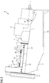
- Fig. 2 shows a bearing arrangement 8 as used in the wind turbine 1 of Fig. 1 .
- the bearing arrangement 8 is shown in a side view in Fig. 2 .
- Fig. 3 illustrates a cross-section of the bearing arrangement 8
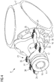
- Fig. 4 illustrates a perspective view of the bearing arrangement 8.
- a bed frame 9 of the bearing arrangement 8 is only shown in Fig. 2 but omitted in Figs. 3 and 4 .
- the bearing arrangement 8 comprises a main shaft 10.
- the main shaft 10 connects the hub 7 to a coupling 11 ( Figs. 3 and 4 ).
- the coupling 11 may be a shrink disc coupling.
- the coupling 11 connects the main shaft 10 to a gearbox 12 ( Fig. 2 ).
- the gearbox 12 is connected to the generator 3 ( Figs. 1 ).
- a shaft axis of the main shaft 10 is denoted by reference numeral A.
- the main shaft 10 may be configured as a hollow shaft ( Fig. 3 ) and may comprise a flange 13 for connecting to the hub 7.
- the bearing arrangement 8 comprises two main bearings 14, 15 supporting the main shaft 10 rotatably.
- the front bearing 14 is arranged close to the hub 7.
- the rear bearing 15 is arranged close to the coupling 11 and the gear box 12.
- both bearings 14, 15 are located outside the gear box 12 and upwind of the gear box 12.
- the gear box 12 and/or the gear box housing may be supported by two torque arms (not shown in detail) that are connected to the bed frame.
- the bearings 14, 15 may be formed as gliding bearings or roller element bearings, in particular spherical bearings.
- the front bearing 14, may be configured to carry radial loads only transmitted from the rotor blades, whereas the rear bearing 15, may be configured to carry both axial and radial loads.
- the bearing arrangement 8 further comprises bearing housings 16, 17.
- a front bearing housing 16 houses the front bearing 14, and a rear bearing housing 17 houses the rear bearing 15.
- Each of the bearing housings 16, 17 supports a respective outer race 18 of the bearings 14, 15 ( Fig. 3 ).
- a respective inner race 19 is fixed to the main shaft 10. Roller elements between the outer and inner race 18, 19 are denoted by reference numeral 20 in Fig. 3 .
- the bearing housings 16, 17 are bolted to the bed frame 9 to transmit loads, in particular non-torsional loads, from the shaft 10 to the bed frame 9.
- each of the bearing housings 16, 17 comprises two feet 21, 22, 23, 24.
- Each of the feet 21, 22, 23, 24 is connected to the bed frame 9 ( Fig. 2 ).
- the front bearing housing 16 comprises a right foot 21 and a left foot 22 each bolted to the bed frame 9.
- the rear bearing housing 17 comprises a right foot 23 and a left foot 24 each bolted to the bed frame 9.
- the bed frame 9 of the bearing arrangement 8 is connected at a lower part 25 thereof ( Fig. 2 ) to a yaw bearing (not shown) which in turn is connected to the tower 5 ( Fig. 1 ).
- a yaw bearing (not shown) which in turn is connected to the tower 5 ( Fig. 1 ).
- the bed frame 9 is able to yaw around a yaw axis which substantially corresponds to the vertical axis of the tower 5.
- the bearing arrangement 8 comprises two stiffening elements 26, 27. As shown in Fig. 4 , the bearing arrangement 8 comprises a right stiffening element 26 arranged laterally on a right side of the shaft 10 when seen from above the wind turbine 1. Further, the bearing arrangement 8 comprises a left stiffening element 27 arranged laterally on a left side of the shaft 10.
- the stiffening elements 26, 27 are solid, one-piece elements.
- Fig. 5 shows a detailed view of one of the stiffening elements 26, 27, for example, the right stiffening element 26 of Fig. 4 .
- the stiffening element 26 extends, exclusively, in one direction E.
- a cross-section of the stiffening element 26 varies along the extension direction E in terms of an area A1, A2, A3 and a width W1, W2, W3 of the cross-section.
- a height H1, H2, H3 of the stiffening element 26 is constant along the extension direction E in this example.
- W denotes a width direction of the stiffening element 26.
- the stiffening element 26 extends, exclusively, in a plane P defined by the extension direction E and the width direction W. That means, the height H1, H2, H3 of the stiffening element 26 is much smaller than a length L of the stiffening element 26 in the extension direction E.
- the shaft axis A of the main shaft 10 is, for example, inclined by an angle ⁇ ( Fig. 2 ) with respect to the horizontal plane H of the wind turbine 1.
- Fig. 2 shows a side view of the bearing arrangement 8 of the wind turbine 1
- the horizontal plane H is shown as a line H in Fig. 2 .
- the stiffening element 26 comprises a front portion 28, a rear portion 29 and between the front and rear portions 28, 29 a middle portion 30. Both the front and rear portions 28, 29 comprise several through holes 31 for connection with the bearing housings 16, 17.
- the cross-section of the stiffening element 26 varies along its extension direction E such that an area A1 of the cross-section at the middle portion 30 is smaller than an area A2 of the cross-section at the front portion 28 and an area A3 of the cross-section at the rear portion 29.
- the cross-section of the stiffening element 26 varies along its extension direction E such that a width W1 of the cross-section at the middle portion 30 is smaller than a width W2 of the cross-section at the front portion 28 and a width W3 of the cross-section at the rear portion 29.
- the middle portion 30 comprises a recess 32 in the width direction W ( Fig. 5 ).
- the recess 32 has a curved shape with a radius R of curvature in the direction towards the shaft axis A ( Fig. 4 ).
- the right stiffening element 26 is connected by means of bolts 33 to the right foot 21 of the front bearing housing 16 and to the bed frame 9.
- the bolts 33 are inserted into the trough holes 31 of the front portion 28 and into through holes (not shown) of the right foot 21 of the front bearing housing 16. Then, the bolts 33 are fastened to the bed plate 9.
- the right stiffening element 26 is connected by means of bolts 34 to the right foot 23 of the rear bearing housing 17 and to the bed frame 9.
- the left stiffening element 27 is bolted in a similar manner as the right stiffening element 26 to the bearing housings 16, 17 and to the bed frame 9 by means of bolts 35, 36 ( Fig. 2 ) .
- the stiffening elements 26, 27 provide a reinforcement of the bearing arrangement 8 such that a deformation of the bearing housings 16, 17 and of the bed frame 9 due to bending moments is significantly reduced. Further, non-torque loads from the rotor blades 6 can be better transmitted to the bed frame 9 and, thus, do not enter the gear box 12.
- the bearing arrangement 8 further comprises a cover structure 37, as shown in Fig. 6 .
- the cover structure 37 covers the main shaft 10 to protect the shaft 10 and/or to protect workers from the shaft 10 rotating during operation.
- the cover structure 37 covers the shaft 10 without being in contact with the shaft 10 such that the shaft 10 can freely rotate.
- the cover structure 37 is connected to the front bearing housing 16 (e.g., by means of bolts, not shown), to the rear bearing housing 17 (e.g., by means of bolts, not shown), and to the stiffening elements 26, 27 (e.g., by means of bolts 38).
- the cover structure 37 comprises, for example, a perforated plate.
- the cover structure 37 may further comprises one or more steps 39. Thus, a worker can walk on the cover structure 37 and, for example, cross the shaft 10 even during operation of the wind turbine.
Abstract
Description
- The present invention relates to a bearing arrangement for a wind turbine and a wind turbine.
- In wind turbines, bearings are used to support the main shaft connecting the rotor to the gear box and/or the generator. The main shaft is subjected to substantial loads from the rotor blades during the operation of the wind turbine. To better absorb non-torque loads from the rotor blades, bearing arrangements of wind turbines often comprise two main bearings supporting the main shaft. Yet, it has been found that conventional bearing arrangements comprising, for example, two separate bearing housings fastened to the bed frame, do not sufficiently absorb non-torque loads in strong wind conditions.
- It is one object of the present invention to provide an improved bearing arrangement for a wind turbine and an improved wind turbine.
- Accordingly, a bearing arrangement for a wind turbine is provided. The bearing arrangement comprises a bed frame and a shaft configured for connecting a rotor with a generator of the wind turbine. The bearing arrangement comprises a front bearing and a rear bearing both supporting the shaft rotatably around a shaft axis. Further, the bearing arrangement comprises a front bearing housing supporting the front bearing. The front bearing housing comprises one or more feet connected to the bed frame. Further, the bearing arrangement comprises a rear bearing housing supporting the rear bearing. The rear bearing housing comprises one or more feet connected to the bed frame. Furthermore, the bearing arrangement comprises a stiffening element connecting one of the feet of the front bearing housing and one of the feet of the rear bearing housing.
- Having the stiffening element allows a reinforcement (stiffening) of the connection between the front bearing housing, the rear bearing housing and the bed frame. In particular, the stiffening element reduces the deformation of the bearing housings and the bed frame. Further, due to the stiffening element a separation and/or sliding of contact surfaces of the bearing housings and the bed frame can be better avoided.
- Thus, the bearing arrangement better transfers non-torque loads (rotor bending loads) to the bed frame. Hence, less bending moments are transmitted from the rotor to the gearbox and/or the generator. With reduced non-torque loads entering the gearbox and/or the generator, damage of the gearbox, the generator and/or the wind turbine is avoided. Further, a conventional bed frame and bearing housings designed for moderate mean wind velocities (e.g., class IIA conditions of mean wind velocities of 8,5 m/s) can be used under mean wind velocities of 10 m/s (class IA) or more by applying the stiffening element.
- The bearing arrangement is part of a wind turbine. A wind turbine is an apparatus to convert the wind's kinetic energy into electrical energy. The wind turbine comprises a rotor having one or more blades and a nacelle comprising the bearing arrangement, the gear box and the generator. The wind turbine further comprises a tower holding, at its top end, the nacelle. The tower of the wind turbine may be connected via a transition piece to a foundation of the wind turbine, such as a monopile in the seabed.
- The front bearing housing, the rear bearing housing and further components of the nacelle, such as the gear box and the generator, are each mounted to the bed frame. The bed frame is, for example, a floor of the nacelle or a portion of the floor of the nacelle. The bed frame is connected to the tower of the wind turbine to transmit loads received, for example from the bearing housings, to the tower. The bed frame may be connected to the tower of the wind turbine by means of a yaw bearing to orient the rotor into the wind.
- The shaft is, for example, configured to directly connect the rotor with the generator. Alternatively, the shaft is configured to connect the rotor with the generator by directly connecting the rotor with a coupling of the gear box and by connecting the gear box with the generator by means of a further shaft.
- The front bearing and the rear bearing are, in particular, two main bearings both supporting the main shaft outside the gear box/gear box housing of the wind turbine. The front bearing is, in particular, arranged closer to the rotor than the rear bearing. The front bearing is, for example, carrying radial loads only. The rear bearing is, for example, carrying both axial and radial loads.
- The gear box and/or the gear box housing may be supported by two torque arms that are connected to the bed frame. Such an arrangement is referred to as a four-point wind turbine drivetrain configuration, as the front bearing, the rear bearing and the two torque arms form four points of support of the main shaft. A four-point wind turbine drivetrain configuration is advantageous over a three-point wind turbine drivetrain configuration comprising only one main bearing because non-torque loads from the rotor blades can be better transmitted to the bed frame.
- The bearing arrangement comprises the stiffening element connecting one of the feet of the front bearing housing and one of the feet of the rear bearing housing, and, in particular, connecting both feet to the bed frame.
- The front bearing housing comprises, for example, a left foot and a right foot with respect to the shaft axis when seen from above. Both the left foot and the right foot of front bearing housing are connected, e.g., bolted, to the bed frame.
- Further, also the rear bearing housing comprises, for example, a left foot and a right foot. Both the left foot and the right foot of the rear bearing housing are connected, e.g., bolted, to the bed frame.
- The stiffening element is, for example, connecting the right foot of the front bearing housing to the right foot of the rear bearing housing and both to the bed frame. The stiffening element is, for example, connecting the left foot of the front bearing housing to the left foot of the rear bearing housing and both to the bed frame.
- In embodiments, the bearing arrangement comprises two stiffening elements, one connecting the right feet of the two bearing housings and one connecting the left feet of the two bearing housings. Further, the right feet and the left feet are, in particular, connected to the bed frame.
- The stiffening element is, for example, a solid, one-piece element (i.e. made from one continuous piece of material).
- According to an embodiment, the stiffening element extends, exclusively, in one plane, the plane of the stiffening element being a horizontal plane and/or a plane inclined to the horizontal plane by an angle by which the shaft axis is inclined to the horizontal plane and/or a plane between the horizontal plane and the inclined plane.
- The stiffening element extending, exclusively, in one plane means that an extension of the stiffening element perpendicular to its extension plane is small in comparison with the extension of the stiffening element in the extension plane. For example, the extension of the stiffening element perpendicular to the extension plane of the stiffening element is smaller than 30%, smaller than 20%, smaller than 15% and/or smaller than 10% of the extension of the stiffening element in the extension plane.
- The stiffening element extending, exclusively, in one plane means, in particular, that the stiffening element has no portion protruding out of the extension plane, e.g., upwards from the extension plane. I.e., the stiffening element is not crossing the shaft axis.
- The horizontal plane is, in particular, a horizontal plane of the wind turbine. The shaft axis may be oriented horizontally or may be inclined with respect to the horizontal plane by an inclination angle. For example, the inclination angle of the shaft axis from the horizontal plane may be between 0 and 20°.
- By having the stiffening element extending, exclusively, in one plane, the reinforcement of the connection between the front bearing housing, the rear bearing housing and the bed frame can be achieved with a simple configuration of the stiffening element.
- According to a further embodiment, the stiffening element extends, exclusively, in one direction and comprises a cross-section varying along its extension direction.
- The stiffening element has, in particular, an elongated shape. The extension direction of the stiffening element is, in particular, a straight connecting line between the one foot of the front bearing housing and the one foot of the rear bearing
housing. - By having the stiffening element extending, exclusively, in one direction, the stiffening element has simple and light weight configuration. In particular, manufacturing, transporting and assembling of the stiffening element is cost and time efficient.
- According to a further embodiment, the stiffening element comprises a front portion and a rear portion. The stiffening element is connected at its front portion to the one foot of the front bearing housing and is connected at its rear portion to the one foot of the rear bearing housing.
- Both the front portion and the rear portion of the stiffening element comprise, in particular, holes and/or through holes for connection with the bearing housings and, in particular, with the bed frame.
- According to a further embodiment, the cross-section of the stiffening element varies along its extension direction such that an area of the cross-section at a middle portion of the stiffening element is smaller than an area of the cross-section at the front portion of the stiffening element and an area of the cross-section at the rear portion of the stiffening element.
- The middle portion is, in particular, arranged between the front portion and the rear portion. The middle portion is, in particular, continuous with the front portion and the rear portion.
- By having the front portion and the rear portion with the larger cross-section, the stiffening element can be stably connected at the front portion and the rear portion to the bearing housings. By having the middle portion with the smaller cross-section, the stiffening element can be configured even lighter.
- According to a further embodiment, a width of the cross-section of the stiffening element at the middle portion is smaller than a width of the cross-section at the front portion and a width of the cross-section at the rear portion.
- By having the front portion and the rear portion with the larger width of the cross-section, the stiffening element can be more stably connected at the front portion and the rear portion to the feet of the bearing housings.
- In embodiments, the middle portion may comprise a recess in a width direction of the stiffening element. The recess may be curved having a radius in the direction towards the shaft axis.
- According to a further embodiment, a height of the cross-section of the stiffening element at the middle portion is equal or larger than a height of the cross-section at the front portion and a height of the cross-section at the rear portion.
- According to a further embodiment, the stiffening element is arranged, exclusively, laterally with respect to the shaft axis when seen from above.
- The stiffening element is, in particular, not crossing above and/or below the shaft axis when seen from above, i.e. when seen from above with respect to the wind turbine.
- By having the stiffening element arranged, exclusively, laterally with respect to the shaft axis when seen from above, the stiffening element can be easier assembled with the bearing housings and the bed frame. Further, an access to the shaft, e.g., for maintenance work, is possible without removing the stiffening element.
- According to a further embodiment, the bearing arrangement comprises first fastening means fastening the stiffening element to the one foot of the front bearing housing and to the bed frame and/or comprises second fastening means fastening the stiffening element to the one foot of the rear bearing housing and the bed frame.
- By fastening the stiffening element to the one foot of the front bearing housing and to the bed frame with the same first fastening means, a direct connection of the stiffening element, the front bearing housing and the bed frame is provided. Likewise, by fastening the stiffening element to the one foot of the rear bearing housing and to the bed frame with the same second fastening means, a direct connection of the stiffening element, the rear bearing housing and the bed frame is provided. Thus, a better reinforcement of the bearing housings and the bed frame can be achieved.
- The stiffening element comprises, in particular, through holes for connection with the bearing housings and the bed frame. For example, both the front portion and the rear portion of the stiffening element comprises the through holes. Further, also the one or more feet of the bearing housings comprise through holes for connection with the stiffening element and the bed frame. The through holes of the stiffening element and the feet may be unthreaded or may be threaded.
- According to a further embodiment, the first fastening means and/or the second fastening means comprise bolts.
- Alternatively, the first fastening means and/or the second fastening means comprise screws.
- According to a further embodiment, the bearing arrangement comprises a cover structure covering the shaft while being spaced apart from the shaft. The cover structure is connected to the front bearing housing, the rear bearing housing and/or the stiffening element.
- By having the cover structure, the shaft can be protected and/or workers can be protected from the shaft rotating during operation. In particular, the cover structure may cover the shaft completely from above such that it bridges the shaft and that workers can walk across the shaft from a left side of the shaft to a right side of the shaft or vice versa.
- According to a further embodiment, the front bearing and/or the rear bearing is a spherical roller bearing.
- For example, the front bearing and/or the rear bearing is a spherical roller bearing comprising two rows of spherical rollers. Alternatively, the front bearing and/or the rear bearing is a tapered roller bearing or another roller element bearing.
- According to a further embodiment, the stiffening element is made from cast iron.
- Thereby, the stiffening element is cheap to manufacture.
- In embodiments, the stiffening element is made from one piece, i.e. it is formed integrally.
- Thus, the stiffening element is easy to manufacture and to configure stiff.
- According to a further aspect, a wind turbine comprising the bearing arrangement as described above is provided.
- According to a further embodiment of the further aspect, the wind turbine comprises a rotor and a generator. The shaft of the bearing arrangement connects the rotor with the generator.
- This includes arrangements where the shaft is coupled using a coupling, for example a shrink disc coupling, to a gearbox. The gearbox in turn may be connected to the generator by another coupling. Hence, the shaft may be connected to the generator directly or indirectly.
- Further possible implementations or alternative solutions of the invention also encompass combinations - that are not explicitly mentioned herein - of features described above or below with regard to the embodiments. The person skilled in the art may also add individual or isolated aspects and features to the most basic form of the invention.
- Further embodiments, features and advantages of the present invention will become apparent from the subsequent description and dependent claims, taken in conjunction with the accompanying drawings, in which:
- Fig. 1
- shows a perspective view of a wind turbine according to an embodiment;
- Fig. 2
- shows a side view of a bearing arrangement of the wind turbine of
Fig. 1 ; - Fig. 3
- shows a cross-section taken from the bearing arrangement of
Fig. 2 along a shaft axis of the main shaft; - Fig. 4
- shows a perspective view of the bearing arrangement of
Fig. 2 ; - Fig. 5
- shows, in a perspective view, a stiffening element of the bearing arrangement of
Fig. 2 ; and - Fig. 6
- shows a perspective view of the bearing arrangement of
Fig. 2 along with a cover structure. - In the Figures, like reference numerals designate like or functionally equivalent elements, unless otherwise indicated.
-
Fig. 1 shows a wind turbine 1 according to an embodiment. - The wind turbine 1 comprises a
rotor 2 connected to a generator 3 arranged inside a nacelle 4. The nacelle 4 is arranged at the upper end of atower 5 of the wind turbine 1. - The
rotor 2 comprises, for example, threerotor blades 6. Therotor blades 6 are connected to a hub 7 of the wind turbine 1.Rotors 2 of this kind may have diameters ranging from, for example, 50 to 160 meters or even more. Therotor blades 6 are subjected to high wind loads. Accordingly, high loads act on a main shaft (not shown inFig. 1 ) connecting the hub 7 to the generator 3. -
Fig. 2 shows a bearing arrangement 8 as used in the wind turbine 1 ofFig. 1 . The bearing arrangement 8 is shown in a side view inFig. 2 .Fig. 3 illustrates a cross-section of the bearing arrangement 8, andFig. 4 illustrates a perspective view of the bearing arrangement 8. Abed frame 9 of the bearing arrangement 8 is only shown inFig. 2 but omitted inFigs. 3 and4 . - The bearing arrangement 8 comprises a
main shaft 10. Themain shaft 10 connects the hub 7 to a coupling 11 (Figs. 3 and4 ). Thecoupling 11 may be a shrink disc coupling. Thecoupling 11 connects themain shaft 10 to a gearbox 12 (Fig. 2 ). Thegearbox 12 is connected to the generator 3 (Figs. 1 ). A shaft axis of themain shaft 10 is denoted by reference numeral A. - The
main shaft 10 may be configured as a hollow shaft (Fig. 3 ) and may comprise aflange 13 for connecting to the hub 7. - As shown in
Fig. 3 , the bearing arrangement 8 comprises twomain bearings 14, 15 supporting themain shaft 10 rotatably. Thefront bearing 14 is arranged close to the hub 7. The rear bearing 15 is arranged close to thecoupling 11 and thegear box 12. In particular, bothbearings 14, 15 are located outside thegear box 12 and upwind of thegear box 12. There may be some additional bearings (not shown) integrated into the gear box. Thegear box 12 and/or the gear box housing may be supported by two torque arms (not shown in detail) that are connected to the bed frame. - The
bearings 14, 15 may be formed as gliding bearings or roller element bearings, in particular spherical bearings. For example, thefront bearing 14, may be configured to carry radial loads only transmitted from the rotor blades, whereas the rear bearing 15, may be configured to carry both axial and radial loads. - As can be seen in
Figs. 2 to 4 , the bearing arrangement 8 further comprises bearinghousings front bearing housing 16 houses thefront bearing 14, and arear bearing housing 17 houses the rear bearing 15. - Each of the bearing
housings outer race 18 of thebearings 14, 15 (Fig. 3 ). A respectiveinner race 19 is fixed to themain shaft 10. Roller elements between the outer andinner race reference numeral 20 inFig. 3 . - The bearing
housings bed frame 9 to transmit loads, in particular non-torsional loads, from theshaft 10 to thebed frame 9. - In particular, as shown in
Fig. 4 , each of the bearinghousings feet feet Fig. 2 ). In particular, thefront bearing housing 16 comprises aright foot 21 and aleft foot 22 each bolted to thebed frame 9. Further, therear bearing housing 17 comprises aright foot 23 and aleft foot 24 each bolted to thebed frame 9. - The
bed frame 9 of the bearing arrangement 8 is connected at alower part 25 thereof (Fig. 2 ) to a yaw bearing (not shown) which in turn is connected to the tower 5 (Fig. 1 ). By having the yaw bearing, thebed frame 9 is able to yaw around a yaw axis which substantially corresponds to the vertical axis of thetower 5. - Ideally, all non-torsional loads from the
shaft 10 are transmitted to thebed plate 9 via the respective fourfeet housings housings bed plate 9. When such non-torque loads enter thegear box 12, they can, for example, damage thegear box 12. - In order to stiffen the connection of the bearing
housings bed plate 9, the bearing arrangement 8 comprises two stiffeningelements Fig. 4 , the bearing arrangement 8 comprises aright stiffening element 26 arranged laterally on a right side of theshaft 10 when seen from above the wind turbine 1. Further, the bearing arrangement 8 comprises aleft stiffening element 27 arranged laterally on a left side of theshaft 10. Thestiffening elements -
Fig. 5 shows a detailed view of one of thestiffening elements right stiffening element 26 ofFig. 4 . The stiffeningelement 26 extends, exclusively, in one direction E. A cross-section of the stiffeningelement 26 varies along the extension direction E in terms of an area A1, A2, A3 and a width W1, W2, W3 of the cross-section. A height H1, H2, H3 of the stiffeningelement 26 is constant along the extension direction E in this example. W denotes a width direction of the stiffeningelement 26. The stiffeningelement 26 extends, exclusively, in a plane P defined by the extension direction E and the width direction W. That means, the height H1, H2, H3 of the stiffeningelement 26 is much smaller than a length L of the stiffeningelement 26 in the extension direction E. - The shaft axis A of the
main shaft 10 is, for example, inclined by an angle α (Fig. 2 ) with respect to the horizontal plane H of the wind turbine 1. AsFig. 2 shows a side view of the bearing arrangement 8 of the wind turbine 1, the horizontal plane H is shown as a line H inFig. 2 . - The stiffening
element 26 comprises afront portion 28, arear portion 29 and between the front andrear portions 28, 29 amiddle portion 30. Both the front andrear portions holes 31 for connection with the bearinghousings - The cross-section of the stiffening
element 26 varies along its extension direction E such that an area A1 of the cross-section at themiddle portion 30 is smaller than an area A2 of the cross-section at thefront portion 28 and an area A3 of the cross-section at therear portion 29. - Further, the cross-section of the stiffening
element 26 varies along its extension direction E such that a width W1 of the cross-section at themiddle portion 30 is smaller than a width W2 of the cross-section at thefront portion 28 and a width W3 of the cross-section at therear portion 29. - In the shown example, the
middle portion 30 comprises arecess 32 in the width direction W (Fig. 5 ). Therecess 32 has a curved shape with a radius R of curvature in the direction towards the shaft axis A (Fig. 4 ). - In order to stiffen the connection of the bearing
housings bed frame 9, theright stiffening element 26 is connected by means ofbolts 33 to theright foot 21 of thefront bearing housing 16 and to thebed frame 9. Thebolts 33 are inserted into the trough holes 31 of thefront portion 28 and into through holes (not shown) of theright foot 21 of thefront bearing housing 16. Then, thebolts 33 are fastened to thebed plate 9. Likewise, theright stiffening element 26 is connected by means ofbolts 34 to theright foot 23 of therear bearing housing 17 and to thebed frame 9. - The
left stiffening element 27 is bolted in a similar manner as theright stiffening element 26 to the bearinghousings bed frame 9 by means ofbolts 35, 36 (Fig. 2 ) . - The
stiffening elements housings bed frame 9 due to bending moments is significantly reduced. Further, non-torque loads from therotor blades 6 can be better transmitted to thebed frame 9 and, thus, do not enter thegear box 12. - The bearing arrangement 8 further comprises a
cover structure 37, as shown inFig. 6 . Thecover structure 37 covers themain shaft 10 to protect theshaft 10 and/or to protect workers from theshaft 10 rotating during operation. - The
cover structure 37 covers theshaft 10 without being in contact with theshaft 10 such that theshaft 10 can freely rotate. Thecover structure 37 is connected to the front bearing housing 16 (e.g., by means of bolts, not shown), to the rear bearing housing 17 (e.g., by means of bolts, not shown), and to thestiffening elements 26, 27 (e.g., by means of bolts 38). Thecover structure 37 comprises, for example, a perforated plate. Thecover structure 37 may further comprises one or more steps 39. Thus, a worker can walk on thecover structure 37 and, for example, cross theshaft 10 even during operation of the wind turbine. - Although the present invention has been described in accordance with preferred embodiments, it is obvious for the person skilled in the art that modifications are possible in all embodiments.
Claims (15)
- A bearing arrangement (8) for a wind turbine (1), comprising:a bed frame (9),a shaft (10) configured for connecting a rotor (2) with a generator (3) of the wind turbine (1),a front bearing (14) and a rear bearing (15) both supporting the shaft (10) rotatably around a shaft axis (A),a front bearing housing (16) supporting the front bearing (14), the front bearing housing (16) comprising one or more feet (21, 22) connected to the bed frame (9),a rear bearing housing (17) supporting the rear bearing (15), the rear bearing housing (17) comprising one or more feet (23, 24) connected to the bed frame (9), anda stiffening element (26, 27) connecting one of the feet (21, 22) of the front bearing housing (16) and one of the feet (23, 24) of the rear bearing housing (17).
- The bearing arrangement according to claim 1,
wherein the stiffening element (26, 27) extends, exclusively, in one plane (P), the plane (P) of the stiffening element (26, 27) being a horizontal plane (H) and/or a plane inclined to the horizontal plane (H) by an angle (α) by which the shaft axis (A) is inclined to the horizontal plane (H) and/or a plane between the horizontal plane (H) and the inclined plane. - The bearing arrangement according to claim 1 or 2,
wherein the stiffening element (26, 27) extends, exclusively, in one direction (E) and comprises a cross-section varying along its extension direction (E). - The bearing arrangement according to one of claims 1 - 3,
wherein the stiffening element (26, 27) comprises a front portion (28) and a rear portion (29), the stiffening element (26, 27) being connected at its front portion (28) to the one foot (21, 22) of the front bearing housing (16) and being connected at its rear portion (29) to the one foot (23, 24) of the rear bearing housing (17). - The bearing arrangement according to one of claim 3 or 4,
wherein the cross-section of the stiffening element (26, 27) varies along its extension direction (E) such that an area (A1) of the cross-section at a middle portion (30) of the stiffening element (26, 27) is smaller than an area (A2) of the cross-section at the front portion (28) of the stiffening element (26, 27) and an area (A3) of the cross-section at the rear portion (29) of the stiffening element (26, 27). - The bearing arrangement according to claim 5,
wherein a width (W1) of the cross-section of the stiffening element (26, 27) at the middle portion (30) is smaller than a width (W2) of the cross-section at the front portion (28) and a width (W3) of the cross-section at the rear portion (29). - The bearing arrangement according to claim 5 or 6,
wherein a height (H1) of the cross-section of the stiffening element (26, 27) at the middle portion (30) is equal or larger than a height (H2) of the cross-section at the front portion (28) and a height (H3) of the cross-section at the rear portion (29). - The bearing arrangement according to one of claims 1 - 7,
wherein the stiffening element (26, 27) is arranged, exclusively, laterally with respect to the shaft axis (A) when seen from above. - The bearing arrangement according to one of claims 1 - 8, comprising first fastening means (33, 35) fastening the stiffening element (26, 27) to the one foot (21, 22) of the front bearing housing (16) and to the bed frame (9) and/or comprising second fastening means (34, 36) fastening the stiffening element (26, 27) to the one foot (23, 24) of the rear bearing housing (17) and the bed frame (9).
- The bearing arrangement according to claim 9, wherein the first fastening means (33, 35) and/or the second fastening means (34, 36) comprise bolts.
- The bearing arrangement according to one of claims 1 - 10, comprising a cover structure (37) covering the shaft (10) while being spaced apart from the shaft (10), the cover structure (37) being connected to the front bearing housing (16), the rear bearing housing (17) and/or the stiffening element (26, 27).
- The bearing arrangement according to one of claims 1 - 11, wherein the front bearing (14) and/or the rear bearing (15) is a spherical roller bearing.
- The bearing arrangement according to one of claims 1 - 12, wherein the stiffening element (26, 27) is made from cast iron.
- A wind turbine (1) comprising the bearing arrangement (8) of any one of claims 1 - 13.
- The wind turbine according to claim 14, comprising a rotor (2) and a generator (3), wherein the shaft (10) of the bearing arrangement (8) connects the rotor (2) with the generator (3).
Priority Applications (3)
| Application Number | Priority Date | Filing Date | Title |
|---|---|---|---|
| EP19380001.8A EP3690239A1 (en) | 2019-01-30 | 2019-01-30 | Bearing arrangement for a wind turbine and wind turbine |
| CN202010067082.7A CN111502933B (en) | 2019-01-30 | 2020-01-20 | Bearing arrangement for a wind turbine and wind turbine |
| US16/748,983 US11454220B2 (en) | 2019-01-30 | 2020-01-22 | Bearing arrangement for a wind turbine and wind turbine |
Applications Claiming Priority (1)
| Application Number | Priority Date | Filing Date | Title |
|---|---|---|---|
| EP19380001.8A EP3690239A1 (en) | 2019-01-30 | 2019-01-30 | Bearing arrangement for a wind turbine and wind turbine |
Publications (1)
| Publication Number | Publication Date |
|---|---|
| EP3690239A1 true EP3690239A1 (en) | 2020-08-05 |
Family
ID=65628724
Family Applications (1)
| Application Number | Title | Priority Date | Filing Date |
|---|---|---|---|
| EP19380001.8A Pending EP3690239A1 (en) | 2019-01-30 | 2019-01-30 | Bearing arrangement for a wind turbine and wind turbine |
Country Status (3)
| Country | Link |
|---|---|
| US (1) | US11454220B2 (en) |
| EP (1) | EP3690239A1 (en) |
| CN (1) | CN111502933B (en) |
Families Citing this family (1)
| Publication number | Priority date | Publication date | Assignee | Title |
|---|---|---|---|---|
| EP3690239A1 (en) * | 2019-01-30 | 2020-08-05 | Siemens Gamesa Renewable Energy Innovation & Technology, S.L. | Bearing arrangement for a wind turbine and wind turbine |
Citations (4)
| Publication number | Priority date | Publication date | Assignee | Title |
|---|---|---|---|---|
| US20110243754A1 (en) * | 2011-02-07 | 2011-10-06 | General Electric Company | Pillow Block for Bed Plate of Wind Turbine |
| US20120134810A1 (en) * | 2011-12-06 | 2012-05-31 | General Electric Company | System and method for detecting and/or controlling loads in a wind turbine |
| US20120134811A1 (en) * | 2011-12-06 | 2012-05-31 | General Electric Company | System and method for detecting and/or controlling loads in a wind turbine |
| EP2754893A1 (en) * | 2012-06-29 | 2014-07-16 | Mitsubishi Heavy Industries, Ltd. | Method for assembling shafting of regenerated energy power generation device, and tool for assembling shafting |
Family Cites Families (23)
| Publication number | Priority date | Publication date | Assignee | Title |
|---|---|---|---|---|
| FR2804726A1 (en) * | 1999-12-24 | 2001-08-10 | Jean Pierre Tromelin | Rotating case gearbox, for wind turbine, has cylindrical casing supported by conical bearings on a stationary hollow mounting beam housing the output shaft |
| CN102648347B (en) * | 2009-10-28 | 2015-07-01 | 维斯塔斯风力系统集团公司 | A wind power installation and methods of using a machine frame in a wind power installation |
| CN201714598U (en) * | 2010-04-16 | 2011-01-19 | 辽宁中科天道新能源装备工业有限公司 | Underframe structure for front generator room of wind generating set |
| US8795567B2 (en) * | 2010-09-23 | 2014-08-05 | The Boeing Company | Method for fabricating highly contoured composite stiffeners with reduced wrinkling |
| CN201821009U (en) * | 2010-10-11 | 2011-05-04 | 上海纳杰电气成套有限公司 | Baseplate connection strengthening rib for retractable 10kv switchgear busbar bridge box |
| WO2012052022A1 (en) * | 2010-10-18 | 2012-04-26 | Vestas Wind Systems A/S | Wind turbine power transmission system |
| ES2738486T3 (en) | 2011-03-08 | 2020-01-23 | Vestas Wind Sys As | Wind turbine rotor shaft support structure |
| DK201170147A (en) * | 2011-03-30 | 2012-02-15 | Vestas Wind Sys As | A hub for a wind turbine |
| US20120025538A1 (en) * | 2011-06-20 | 2012-02-02 | Michael James Luneau | Unitary support frame for use in wind turbines and methods for fabricating same |
| KR20140003125U (en) * | 2012-11-19 | 2014-05-28 | 대우조선해양 주식회사 | Bearing structure and wind power generator having the same |
| DE202012011274U1 (en) * | 2012-11-24 | 2014-02-25 | Eolotec Gmbh | Prestressed bearing unit, in particular for a wind power plant |
| CN203645430U (en) * | 2013-10-30 | 2014-06-11 | 浙江伯力电机有限公司 | Motor |
| CN203730576U (en) * | 2013-12-31 | 2014-07-23 | 常州市大华环宇机械制造有限公司 | Bearing seat of wind turbine generator unit |
| DE102014209399A1 (en) * | 2014-05-19 | 2015-11-19 | Schaeffler Technologies AG & Co. KG | storage unit |
| EP3141747B1 (en) | 2015-09-08 | 2020-09-02 | Siemens Gamesa Renewable Energy A/S | Reinforced bearing of a wind turbine |
| ES2617973B1 (en) * | 2015-12-18 | 2018-04-12 | Gamesa Innovation & Technology S.L. | Wind turbine with a modular power train |
| CN205383043U (en) * | 2016-01-26 | 2016-07-13 | 李勇强 | Directly drive narrow pipe of acceleration rate formula and gather swift as wind electricity with framework device |
| CN109416025A (en) * | 2016-06-30 | 2019-03-01 | 维斯塔斯风力系统有限公司 | Cabin base framework component for wind turbine |
| CN107269721A (en) * | 2017-07-28 | 2017-10-20 | 江苏安捷利机电科技有限公司 | A kind of Special-shaped rear axle of electric automobile support of bearing |
| CN207500065U (en) * | 2017-10-25 | 2018-06-15 | 大连金山压缩机制造有限公司 | Novel 4.0MW wind turbines forward spindle bearing |
| CN207634253U (en) * | 2017-12-06 | 2018-07-20 | 上海电气风电集团有限公司 | A kind of component of built-up shaft bearing and forebay |
| US10677223B2 (en) * | 2018-09-17 | 2020-06-09 | General Electric Company | Method of customizing a wind turbine bedplate via additive manufacturing |
| EP3690239A1 (en) * | 2019-01-30 | 2020-08-05 | Siemens Gamesa Renewable Energy Innovation & Technology, S.L. | Bearing arrangement for a wind turbine and wind turbine |
-
2019
- 2019-01-30 EP EP19380001.8A patent/EP3690239A1/en active Pending
-
2020
- 2020-01-20 CN CN202010067082.7A patent/CN111502933B/en active Active
- 2020-01-22 US US16/748,983 patent/US11454220B2/en active Active
Patent Citations (4)
| Publication number | Priority date | Publication date | Assignee | Title |
|---|---|---|---|---|
| US20110243754A1 (en) * | 2011-02-07 | 2011-10-06 | General Electric Company | Pillow Block for Bed Plate of Wind Turbine |
| US20120134810A1 (en) * | 2011-12-06 | 2012-05-31 | General Electric Company | System and method for detecting and/or controlling loads in a wind turbine |
| US20120134811A1 (en) * | 2011-12-06 | 2012-05-31 | General Electric Company | System and method for detecting and/or controlling loads in a wind turbine |
| EP2754893A1 (en) * | 2012-06-29 | 2014-07-16 | Mitsubishi Heavy Industries, Ltd. | Method for assembling shafting of regenerated energy power generation device, and tool for assembling shafting |
Also Published As
| Publication number | Publication date |
|---|---|
| US20200240396A1 (en) | 2020-07-30 |
| CN111502933A (en) | 2020-08-07 |
| CN111502933B (en) | 2023-02-03 |
| US11454220B2 (en) | 2022-09-27 |
Similar Documents
| Publication | Publication Date | Title |
|---|---|---|
| US7857599B2 (en) | Method and apparatus for forming wind turbine machines | |
| US7614850B2 (en) | Apparatus for assembling rotary machines | |
| CA2679779C (en) | Wind turbine rotor | |
| JP2007536454A (en) | Wind turbine for power generation | |
| KR101890436B1 (en) | Gear box, seal, and cover arrangements | |
| RU2564734C2 (en) | Windmill power generator | |
| US9915245B2 (en) | Reinforced pitch bearing of a wind turbine | |
| US9074581B2 (en) | Cone angle insert for wind turbine rotor | |
| US20090317256A1 (en) | Rotor hub of a wind energy plant | |
| US8562300B2 (en) | Wind turbine with high solidity rotor | |
| US9752556B1 (en) | Multi-rotor vertical axis wind turbine | |
| US8203230B2 (en) | Yaw bearing system | |
| US8441142B2 (en) | Bearing device for a wind turbine nacelle | |
| CA2216975A1 (en) | Vertical axis wind turbine | |
| US11454220B2 (en) | Bearing arrangement for a wind turbine and wind turbine | |
| EP3633190A1 (en) | A bearing arrangement for a wind turbine, wind turbine and method for manufacturing a wind turbine | |
| KR102473253B1 (en) | Rotor bearing housing, and wind power plant with rotor bearing housing | |
| US20130171002A1 (en) | Hybrid Wind Turbine Tower with Integrated Yaw Bearing System | |
| WO2011056121A1 (en) | Wind turbine with turbine blades | |
| KR102288688B1 (en) | Twin Blade Type Wind Turbine | |
| US20040184909A1 (en) | Multi-rotor blade stackable vertical axis windmill | |
| JP6887933B2 (en) | Wind power generator | |
| GB2413367A (en) | Wind turbine | |
| US20160053746A1 (en) | A hub and bearing system and a turbine comprising the hub and bearing system | |
| WO2019023005A1 (en) | Vertical-axis wind turbine with multi-point bearing support |
Legal Events
| Date | Code | Title | Description |
|---|---|---|---|
| PUAI | Public reference made under article 153(3) epc to a published international application that has entered the european phase |
Free format text: ORIGINAL CODE: 0009012 |
|
| STAA | Information on the status of an ep patent application or granted ep patent |
Free format text: STATUS: THE APPLICATION HAS BEEN PUBLISHED |
|
| AK | Designated contracting states |
Kind code of ref document: A1 Designated state(s): AL AT BE BG CH CY CZ DE DK EE ES FI FR GB GR HR HU IE IS IT LI LT LU LV MC MK MT NL NO PL PT RO RS SE SI SK SM TR |
|
| AX | Request for extension of the european patent |
Extension state: BA ME |
|
| STAA | Information on the status of an ep patent application or granted ep patent |
Free format text: STATUS: REQUEST FOR EXAMINATION WAS MADE |
|
| 17P | Request for examination filed |
Effective date: 20210105 |
|
| RBV | Designated contracting states (corrected) |
Designated state(s): AL AT BE BG CH CY CZ DE DK EE ES FI FR GB GR HR HU IE IS IT LI LT LU LV MC MK MT NL NO PL PT RO RS SE SI SK SM TR |
|
| STAA | Information on the status of an ep patent application or granted ep patent |
Free format text: STATUS: EXAMINATION IS IN PROGRESS |
|
| 17Q | First examination report despatched |
Effective date: 20220411 |