EP2754774A1 - Zwischenschicht für eine Belagskonstruktion - Google Patents
Zwischenschicht für eine Belagskonstruktion Download PDFInfo
- Publication number
- EP2754774A1 EP2754774A1 EP14151087.5A EP14151087A EP2754774A1 EP 2754774 A1 EP2754774 A1 EP 2754774A1 EP 14151087 A EP14151087 A EP 14151087A EP 2754774 A1 EP2754774 A1 EP 2754774A1
- Authority
- EP
- European Patent Office
- Prior art keywords
- layer
- adhesive
- intermediate layer
- mesh fabric
- mesh
- Prior art date
- Legal status (The legal status is an assumption and is not a legal conclusion. Google has not performed a legal analysis and makes no representation as to the accuracy of the status listed.)
- Granted
Links
Images




Classifications
-
- B—PERFORMING OPERATIONS; TRANSPORTING
- B32—LAYERED PRODUCTS
- B32B—LAYERED PRODUCTS, i.e. PRODUCTS BUILT-UP OF STRATA OF FLAT OR NON-FLAT, e.g. CELLULAR OR HONEYCOMB, FORM
- B32B5/00—Layered products characterised by the non- homogeneity or physical structure, i.e. comprising a fibrous, filamentary, particulate or foam layer; Layered products characterised by having a layer differing constitutionally or physically in different parts
- B32B5/02—Layered products characterised by the non- homogeneity or physical structure, i.e. comprising a fibrous, filamentary, particulate or foam layer; Layered products characterised by having a layer differing constitutionally or physically in different parts characterised by structural features of a fibrous or filamentary layer
- B32B5/024—Woven fabric
-
- B—PERFORMING OPERATIONS; TRANSPORTING
- B32—LAYERED PRODUCTS
- B32B—LAYERED PRODUCTS, i.e. PRODUCTS BUILT-UP OF STRATA OF FLAT OR NON-FLAT, e.g. CELLULAR OR HONEYCOMB, FORM
- B32B5/00—Layered products characterised by the non- homogeneity or physical structure, i.e. comprising a fibrous, filamentary, particulate or foam layer; Layered products characterised by having a layer differing constitutionally or physically in different parts
- B32B5/02—Layered products characterised by the non- homogeneity or physical structure, i.e. comprising a fibrous, filamentary, particulate or foam layer; Layered products characterised by having a layer differing constitutionally or physically in different parts characterised by structural features of a fibrous or filamentary layer
- B32B5/028—Net structure, e.g. spaced apart filaments bonded at the crossing points
-
- B—PERFORMING OPERATIONS; TRANSPORTING
- B32—LAYERED PRODUCTS
- B32B—LAYERED PRODUCTS, i.e. PRODUCTS BUILT-UP OF STRATA OF FLAT OR NON-FLAT, e.g. CELLULAR OR HONEYCOMB, FORM
- B32B5/00—Layered products characterised by the non- homogeneity or physical structure, i.e. comprising a fibrous, filamentary, particulate or foam layer; Layered products characterised by having a layer differing constitutionally or physically in different parts
- B32B5/22—Layered products characterised by the non- homogeneity or physical structure, i.e. comprising a fibrous, filamentary, particulate or foam layer; Layered products characterised by having a layer differing constitutionally or physically in different parts characterised by the presence of two or more layers which are next to each other and are fibrous, filamentary, formed of particles or foamed
- B32B5/24—Layered products characterised by the non- homogeneity or physical structure, i.e. comprising a fibrous, filamentary, particulate or foam layer; Layered products characterised by having a layer differing constitutionally or physically in different parts characterised by the presence of two or more layers which are next to each other and are fibrous, filamentary, formed of particles or foamed one layer being a fibrous or filamentary layer
- B32B5/26—Layered products characterised by the non- homogeneity or physical structure, i.e. comprising a fibrous, filamentary, particulate or foam layer; Layered products characterised by having a layer differing constitutionally or physically in different parts characterised by the presence of two or more layers which are next to each other and are fibrous, filamentary, formed of particles or foamed one layer being a fibrous or filamentary layer another layer next to it also being fibrous or filamentary
-
- E—FIXED CONSTRUCTIONS
- E04—BUILDING
- E04F—FINISHING WORK ON BUILDINGS, e.g. STAIRS, FLOORS
- E04F15/00—Flooring
- E04F15/18—Separately-laid insulating layers; Other additional insulating measures; Floating floors
- E04F15/182—Underlayers coated with adhesive or mortar to receive the flooring
-
- E—FIXED CONSTRUCTIONS
- E04—BUILDING
- E04F—FINISHING WORK ON BUILDINGS, e.g. STAIRS, FLOORS
- E04F15/00—Flooring
- E04F15/18—Separately-laid insulating layers; Other additional insulating measures; Floating floors
- E04F15/186—Underlayers covered with a mesh or the like
-
- E—FIXED CONSTRUCTIONS
- E04—BUILDING
- E04F—FINISHING WORK ON BUILDINGS, e.g. STAIRS, FLOORS
- E04F15/00—Flooring
- E04F15/18—Separately-laid insulating layers; Other additional insulating measures; Floating floors
- E04F15/20—Separately-laid insulating layers; Other additional insulating measures; Floating floors for sound insulation
- E04F15/203—Separately-laid layers for sound insulation
Definitions
- the invention relates to an intermediate layer for a lining construction, comprising a first layer having a first main side and a second main side, formed as a mesh fabric with intersecting threads.
- the mesh fabric comprises threads, which are usually formed as glass fibers. Such a mesh fabric is also referred to as a glass mesh fabric.
- the mesh fabric is used as an intermediate layer in covering constructions and is embedded, for example, in a tile adhesive, so that the mesh fabric is subsequently arranged between the substrate and the tile covering.
- the mesh fabric absorbs stresses introduced via the substrate and prevents these stresses from being transmitted to the tile covering, where these can lead to cracking.
- the invention has for its object to provide an intermediate layer comprising a mesh fabric, which allows a mechanical decoupling of the tile covering from the substrate.
- a second layer formed over the entire surface is arranged at least on the first main side of the first layer.
- the second layer is formed over the entire surface, so that a tile adhesive, which is applied to the mesh fabric, not by the Mesh fabric can extend through to the ground.
- the intermediate layer is placed on the substrate, a tile adhesive is applied to the mesh fabric and then the tile covering is embedded in the tile adhesive. The tile covering is mechanically separated from the substrate, so that the intermediate layer forms a decoupling mat.
- the intermediate layer may be formed as a plate product or as a roll product.
- the second layer comprises at least one adhesive layer.
- the intermediate layer is equipped with a self-adhesive layer. Through the adhesive layer, the intermediate layer can be firmly bonded to the substrate, so that the intermediate layer can not shift during assembly of the tile covering.
- the adhesive layer is covered with a cover film prior to assembly of the intermediate layer. This is deducted prior to assembly of the intermediate layer.
- the second layer is formed as a plastic layer.
- the thickness of the second layer is preferably between 0.1 mm and 1.5 mm.
- Such a plastic layer is inexpensive to produce and has advantageous mechanical properties.
- the second layer may comprise a plastic film.
- the plastic film improves the mechanical properties, in particular the tensile strength of the second layer.
- the plastic film is preferably formed from polyethylene or polypropylene. Both materials are inexpensive and, moreover, impermeable to water.
- the plastic film serves as a moisture-impermeable layer, so that the intermediate layer in addition to the decoupling also serves the seal.
- the plastic film may be provided on one or both sides with an adhesive layer.
- the intermediate layer comprises a first layer and a second layer, wherein the second layer comprises a plastic film, which is provided on both sides with an adhesive layer.
- An adhesive layer serves to connect the second layer to the first layer and the other adhesive layer serves to connect the intermediate layer to the substrate.
- the second layer may also include a metal liner, such as an aluminum liner, to enhance the sealing effect.
- a metal liner such as an aluminum liner
- the metal lamination also improves the heat conduction and the heat distribution on the substrate, so that an intermediate layer provided with a metal lamination is particularly well suited for floor structures with underfloor heating.
- the second layer may be provided with a fiber reinforcement.
- the fiber reinforcement is preferably formed in the form of a grid, which has finer threads in comparison to the mesh fabric of the first layer.
- the fiber reinforcement of the second layer improves the dimensional stability. This is especially true when the second layer in addition to the fiber reinforcement exclusively has a resilient plastic adhesive.
- the adhesive layer preferably comprises a butyl adhesive, an acrylate adhesive or a cold adhesive.
- a cold glue is based on bitumen and, like butyl glue or acrylate glue, is liable to adhere to concrete substrates and the like at ambient temperatures. This ensures that the intermediate layer provided with these adhesives adheres to conventional substrates.
- the second layer may comprise a nonwoven fabric, wherein the nonwoven fabric is preferably mounted on a plastic film and formed flat as a nonwoven layer.
- the intermediate layer comprises a first layer and a second layer, wherein the second layer comprises an adhesive layer and a nonwoven layer.
- the adhesive layer is arranged between the first layer and nonwoven layer.
- the adhesive layer to be applied to the substrate can be designed, for example, as a thin-bed adhesive, as a fixing adhesive layer or as a liquid-sealing layer.
- An intermediate layer formed in this way comprises a first layer, formed as a mesh fabric, on which a second layer formed as a nonwoven fabric is applied. The connection between the first layer and the second layer can be effected mechanically by entangling the fibers or by local melting of the nonwoven fabric or by means of adhesive.
- the mesh size of the mesh fabric is less than 5 mm and is preferably between 1.5 mm and 3 mm. This relatively small mesh size is advantageous since, with larger mesh sizes, the second layer can push through the first layer. This is especially true when the second layer is elastic.
- a third layer can be arranged, formed as a mesh fabric.
- the first layer and the third layer may be connected to one another by means of separate fastening means or by material bonding.
- a higher structure results Intermediate layer, wherein both the first layer and the third layer are mechanically resilient. As a result, this results in a particularly rigid design of the intermediate layer.
- the bending stiffness of the intermediate layer increases again when the first layer and the third layer are connected to one another via spacers.
- the first layer and the third layer are spaced from each other.
- FIG. 1 shows in plan view, an intermediate layer 1 for a lining construction 2.
- a lining construction 2 come in particular floor structures with mineral coverings, such as tiles or tile coverings into consideration.
- the intermediate layer 1 comprises a layer 3 with a first main side 4 and a second main side 5, formed as a mesh fabric with intersecting threads 6.
- An advantageous embodiment of a mesh fabric comprises warp threads and weft threads, wherein in each case a plurality of weft threads to a main thread are summarized, which wrap around the warp threads such that each main thread some weft threads above the warp threads and some weft threads below the warp threads.
- the threads 6 are made in this embodiment of glass fibers. However, other materials, such as carbon or metal are conceivable.
- the mesh size of the threads 6 is less than 5 mm, in this embodiment, the mesh size is 2 mm.
- the thread width is 0.8 mm.
- a second layer 7 is arranged, which is flat and the first layer 3 covered over its entire surface. As a result, no materials can push through the first layer 3 via the first main side 4.
- the second layer 7 is formed as an adhesive layer and comprises a sheet-formed acrylate adhesive. Alternatively, the adhesive layer may also consist of butyl adhesive or a cold adhesive.
- the second layer 7 is inexpensively formed as a plastic layer and has a thickness between 0.1 mm and 1.5 mm.
- the second layer 7 comprises a plastic film made of polyethylene, which is provided on both sides with an adhesive layer.
- a first adhesive layer serves for the cohesive connection of the first layer 3 and the second layer 7 and a second adhesive layer serves for the adhesive bonding of the intermediate layer 1 to the substrate.
- the second layer 7 may comprise a nonwoven layer, which also covers the first layer 3 over the entire surface.
- the second layer 7 is provided with an adhesive layer, which binds the second layer 7 to the first layer 3 in a materially bonded manner.
- a further advantageous embodiment of an intermediate layer 1 comprises a first layer 3, formed as a mesh fabric, wherein on the first main side 4 of the first layer 3, a second layer 7 is arranged.
- the second layer 7 comprises a plastic film, preferably a polyethylene film, which on the side facing the first layer 3 with a Adhesive layer, for example, has a full surface applied to the plastic film acrylate adhesive.
- the adhesive layer serves to connect the second layer 7 to the first layer 3.
- the second layer 7 On the side facing away from the first layer 3, which faces the substrate after assembly, the second layer 7 has a nonwoven layer.
- the nonwoven layer is thermally bonded to the plastic film.
- Such provided with a nonwoven layer plastic film is also known as a vapor barrier or vapor barrier.
- the intermediate layer 1 may be formed as a plate product or as a sheet product.
- FIG. 2 shows the embodiment according to FIG. 1 in the side view.
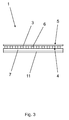
- FIG. 3 shows the embodiment according to FIG. 1 , wherein the second layer 7 is covered with a release liner 11 to improve the handling and to protect the adhesive layer.
- the peel-off film 11 is removed before laying the intermediate layer 1.
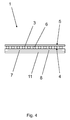
- FIG. 4 shows the embodiment according to FIG. 3 , wherein the second layer 7 is provided with a fiber reinforcement 8 for improving the dimensional stability.
- the fiber reinforcement 8 is formed in the form of a mesh fabric, which has in comparison to the mesh fabric of the first layer 3 finer threads, which are present in a larger mesh size.
- the fiber reinforcement 8 is embedded in the second layer 7.
- FIG. 5 shows the embodiment according to FIG. 4 , wherein in addition to the second main page 5, a third layer 9 is arranged.
- the third layer 9 is also formed as a mesh fabric. Compared to the mesh fabric of the first layer 3, the mesh fabric of the third layer 9 has a larger mesh size and wider threads.
- the mesh size of the third layer 9 is 10 mm.
- the thread width is 2 mm.
- FIG. 6 shows the embodiment according to FIG. 5 wherein the first layer 3 and the third layer 9 in this embodiment are interconnected by spacers 10.
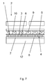
- FIG. 7 shows a lining construction 2 with an intermediate layer 1 according to FIG. 6
- the intermediate layer 1 is placed on the substrate 12 after removal of the release liner 11 and adheres there via the adhesive layer of the second layer 7.
- a tile adhesive is applied to the intermediate layer 1, which penetrates through the third layer 9 through the first layer 3 and is firmly integrated into the meshes of the first layer 3 and the third layer 9 after curing.
- the tile adhesive tiles are embedded in the tile adhesive. Since the tile adhesive does not penetrate the second layer 7, the tiles are firmly connected to the intermediate layer 1, but decoupled from the substrate 12.
- the plastic film of the second layer 7 causes a seal against moisture.
Landscapes
- Engineering & Computer Science (AREA)
- Architecture (AREA)
- Civil Engineering (AREA)
- Structural Engineering (AREA)
- Textile Engineering (AREA)
- Laminated Bodies (AREA)
- Floor Finish (AREA)
Abstract
Description
- Die Erfindung betrifft eine Zwischenschicht für eine Belagskonstruktion, umfassend eine erste Schicht mit einer ersten Hauptseite und einer zweiten Hauptseite, ausgebildet als Gittergewebe mit sich kreuzenden Fäden.
- Das Gittergewebe umfasst Fäden, welche meist als Glasfasern ausgebildet sind. Ein derartiges Gittergewebe wird auch als Glasgittergewebe bezeichnet. Das Gittergewebe findet Verwendung als Zwischenschicht in Belagskonstruktionen und wird beispielsweise in einen Fliesenkleber eingebettet, so dass das Gittergewebe anschließend zwischen Untergrund und Fliesenbelag angeordnet ist. Das Gittergewebe nimmt dabei über den Untergrund eingetragene Spannungen auf und verhindert, dass diese Spannungen in den Fliesenbelag weitergeleitet werden, wo diese zu Rissbildung führen können.
- Aus dem Stand der Technik ist es bekannt, die Fäden des Gittergewebes auf einer Hauptseite mit einem Klebemittel zu beschichten, so dass das Gittergewebe während der Montage auf einem Untergrund fixiert werden kann. Der Vorteil liegt darin, dass das Gittergewebe während der Montagearbeiten nicht verrutschen kann. Bei dieser Ausgestaltung drückt sich jedoch der Fliesenkleber durch die Maschen des Gittergewebes hindurch, so dass das Gittergewebe fest in den Verbund zwischen Untergrund und Fliesenbelag eingebettet ist. Somit werden innerhalb des Untergrundes auftretende Bewegungen nach wie vor in den Fliesenbelag übertragen. Des Weiteren erfolgt auch eine direkte Schallübertragung über den Fliesenbelag in den Untergrund.
- Der Erfindung liegt die Aufgabe zugrunde, eine ein Gittergewebe umfassende Zwischenschicht bereitzustellen, welche eine mechanische Entkopplung des Fliesenbelags von dem Untergrund ermöglicht.
- Diese Aufgabe wird mit den Merkmalen von Anspruch 1 gelöst. Auf vorteilhafte Ausgestaltungen nehmen die Unteransprüche Bezug.
- Zur Lösung der Aufgabe ist zumindest auf der ersten Hauptseite der ersten Schicht eine zweite vollflächig ausgebildete Schicht angeordnet. Im Gegensatz zu der bekannten Beschichtung der Fäden, bei der lediglich ein Klebemittel einseitig und ausschließlich auf den Fäden aufgebracht ist, ist bei der erfindungsgemäßen Ausgestaltung die zweite Schicht vollflächig ausgebildet, so dass sich ein Fliesenkleber, welcher auf das Gittergewebe aufgebracht wird, nicht durch das Gittergewebe hindurch bis auf den Untergrund erstrecken kann. Zur Montage wird die Zwischenschicht auf den Untergrund aufgelegt, ein Fliesenkleber wird auf das Gittergewebe aufgebracht und anschließend wird der Fliesenbelag in den Fliesenkleber eingebettet. Dabei ist der Fliesenbelag mechanisch von dem Untergrund getrennt, so dass die Zwischenschicht eine Entkopplungsmatte bildet. Die Zwischenschicht kann als Plattenware oder als Rollenware ausgebildet sein.
- Vorzugsweise umfasst die zweite Schicht wenigstens eine Klebeschicht. In einer vorteilhaften Ausgestaltung ist die Zwischenschicht mit einer Selbstklebeschicht ausgerüstet. Durch die Klebeschicht kann die Zwischenschicht stoffschlüssig mit dem Untergrund verbunden werden, so dass sich die Zwischenschicht während der Montage des Fliesenbelags nicht verschieben kann. Vorzugsweise ist dabei die Klebeschicht vor der Montage der Zwischenschicht mit einer Abdeckfolie überdeckt. Diese wird vor der Montage der Zwischenschicht abgezogen.
- Vorzugsweise ist die zweite Schicht als Kunststoffschicht ausgebildet. Die Dicke der zweiten Schicht beträgt dabei vorzugsweise zwischen 0,1 mm und 1,5 mm. Eine derartige Kunststoffschicht ist kostengünstig herstellbar und weist vorteilhafte mechanische Eigenschaften auf.
- Darüber hinaus kann die zweite Schicht eine Kunststofffolie umfassen. Die Kunststofffolie verbessert die mechanischen Eigenschaften, insbesondere die Zugfestigkeit der zweiten Schicht. Die Kunststofffolie ist vorzugsweise aus Polyethylen oder Polypropylen gebildet. Beide Werkstoffe sind kostengünstig und darüber hinaus wasserundurchlässig. Dadurch dient die Kunststofffolie als feuchtigkeitsundurchlässige Schicht, so dass die Zwischenschicht neben der Entkopplung auch der Abdichtung dient. Die Kunststofffolie kann einseitig oder beidseitig mit einer Klebeschicht versehen sein. In einer vorteilhaften Ausgestaltung umfasst die Zwischenschicht eine erste Schicht und eine zweite Schicht, wobei die zweite Schicht eine Kunststofffolie umfasst, welche beidseitig mit einer Klebeschicht versehen ist. Eine Klebeschicht dient dabei der Anbindung der zweiten Schicht an die erste Schicht und die andere Klebeschicht dient der Anbindung der Zwischenschicht an den Untergrund.
- Die zweite Schicht kann auch eine Metallkaschierung, beispielsweise eine Aluminium-Kaschierung umfassen, um die Abdichtwirkung zu verbessern. Die Metallkaschierung verbessert darüber hinaus auch die Wärmeleitung und die Wärmeverteilung auf dem Untergrund, so dass eine mit einer Metallkaschierung versehene Zwischenschicht besonders gut für Fußbodenaufbauten mit Fußbodenheizungen geeignet ist.
- Die zweite Schicht kann mit einer Faserverstärkung versehen sein. Dabei ist die Faserverstärkung vorzugsweise in Form eines Gitters ausgebildet, welches im Vergleich zu dem Gittergewebe der ersten Schicht feinere Fäden aufweist. Die Faserverstärkung der zweiten Schicht bewirkt eine Verbesserung der Dimensionsstabilität. Dies gilt insbesondere dann, wenn die zweite Schicht neben der Faserverstärkung ausschließlich einen elastischen Kunststoff kleber aufweist.
- Die Klebeschicht umfasst vorzugsweise einen Butylkleber, einen Acrylatkleber oder einen Kaltkleber. Ein Kaltkleber basiert auf Bitumen und ist ebenso wie Butylkleber oder Acrylatkleber geeignet, bei Umgebungstemperaturen auf Betonuntergründen und dergleichen zu haften. Dadurch ist gewährleistet, dass die mit diesen Klebstoffen versehene Zwischenschicht auf üblichen Untergründen haftet.
- Die zweite Schicht kann einen Vliesstoff umfassen, wobei der Vliesstoff vorzugsweise auf einer Kunststofffolie angebracht und als Vlieslage flächig ausgebildet ist. In einer vorteilhaften Ausgestaltung umfasst die Zwischenschicht eine erste Schicht und eine zweite Schicht, wobei die zweite Schicht eine Klebeschicht und eine Vlieslage umfasst. Die Klebeschicht ist zwischen erster Schicht und Vlieslage angeordnet. Bei dieser Ausgestaltung ist es jedoch erforderlich, eine Klebeschicht auf den Untergrund aufzubringen. Die auf den Untergrund aufzubringende Klebeschicht kann beispielweise als Dünnbettkleber, als Fixierungsklebeschicht oder als Flüssigabdichtungsschicht ausgebildet sein. Eine derartig ausgebildete Zwischenschicht umfasst eine erste Schicht, ausgebildet als Gittergewebe, auf welches eine als Vliesstoff ausgebildete zweite Schicht aufgebracht ist. Die Verbindung zwischen erster Schicht und zweiter Schicht kann mechanisch durch Verschlingen der Fasern oder durch lokales Aufschmelzen des Vliesstoffes oder mittels Klebstoff erfolgen.
- Vorteilhafterweise ist die Maschenweite des Gittergewebes kleiner als 5 mm und beträgt vorzugsweise zwischen 1,5 mm und 3 mm. Diese verhältnismäßig kleine Maschenweite ist vorteilhaft, da sich bei größeren Maschenweiten die zweite Schicht durch die erste Schicht hindurchdrücken kann. Dies gilt insbesondere dann, wenn die zweite Schicht elastisch ausgebildet ist.
- Auf der zweiten Hauptseite kann eine dritte Schicht angeordnet sein, ausgebildet als Gittergewebe. Die erste Schicht und die dritte Schicht können mittels separater Befestigungsmittel oder stoffschlüssig miteinander verbunden sein. Bei dieser Ausgestaltung ergibt sich ein höherer Aufbau der Zwischenschicht, wobei sowohl die erste Schicht als auch die dritte Schicht mechanisch belastbar sind. Im Ergebnis ergibt sich dadurch eine besonders biegesteife Ausgestaltung der Zwischenschicht.
- Die Biegesteifigkeit der Zwischenschicht vergrößert sich noch einmal, wenn die erste Schicht und die dritte Schicht über Abstandshalter miteinander verbunden sind. Bei dieser Ausgestaltung sind die erste Schicht und die dritte Schicht voneinander beabstandet.
- Einige Ausführungsbeispiele der erfindungsgemäßen Zwischenschicht werden nachfolgend anhand der Figuren näher erläutert. Diese zeigen, jeweils schematisch:
- Fig. 1
- eine Zwischenschicht in der Draufsicht;
- Fig. 2
- eine Zwischenschicht in der Seitenansicht;
- Fig. 3
- eine Zwischenschicht mit einer Kunststofffolie auf der zweiten Schicht;
- Fig. 4
- eine Zwischenschicht mit Faserverstärkung in der zweiten Schicht;
- Fig. 5
- eine Zwischenschicht mit einer auf der ersten Schicht angeordneten dritten Schicht;
- Fig. 6
- eine Zwischenschicht mit Abstandshaltern zwischen erster und zweiter Schicht;
- Fig. 7
- eine Belagskonstruktion mit erfindungsgemäßer Zwischenschicht.
-
Figur 1 zeigt in der Draufsicht eine Zwischenschicht 1 für eine Belagskonstruktion 2. Als Belagskonstruktion 2 kommen insbesondere Bodenaufbauten mit mineralischen Belägen, beispielsweise Fliesen oder Plattenbelägen in Betracht. Es ist jedoch auch vorteilhaft, Holzböden mit einer Zwischenschicht 1 zu versehen. Die Zwischenschicht 1 umfasst eine Schicht 3 mit einer ersten Hauptseite 4 und einer zweiten Hauptseite 5, ausgebildet als Gittergewebe mit sich kreuzenden Fäden 6. - Eine vorteilhafte Ausgestaltung eines Gittergewebes umfasst Kettfäden und Schussfäden, wobei jeweils mehrere Schussfäden zu einem Hauptfaden zusammengefasst sind, welche die Kettfäden derart umschlingen, dass je Hauptfaden einige Schussfäden oberhalb der Kettfäden und einige Schussfäden unterhalb der Kettfäden verlaufen. Die Fäden 6 bestehen in dieser Ausgestaltung aus Glasfasern. Es sind jedoch auch andere Werkstoffe, beispielsweise Carbon oder Metall denkbar. Die Maschenweite der Fäden 6 ist kleiner als 5 mm, in dieser Ausgestaltung beträgt die Maschenweite 2 mm. Die Fadenbreite beträgt 0,8 mm.
- Auf der ersten Hauptseite 4 ist eine zweite Schicht 7 angeordnet, welche flächig ausgebildet ist und die erste Schicht 3 vollflächig bedeckt. Dadurch können sich keinerlei Materialien über die erste Hauptseite 4 durch die erste Schicht 3 hindurchdrücken. Die zweite Schicht 7 ist als Klebeschicht ausgebildet und umfasst einen flächig ausgebildeten Acrylatkleber. Alternativ kann die Klebeschicht auch aus Butylkleber oder einen Kaltkleber bestehen. Die zweite Schicht 7 ist kostengünstig als Kunststoffschicht ausgebildet und weist eine Dicke zwischen 0,1 mm und 1,5 mm auf.
- In einer vorteilhaften Ausgestaltung umfasst die zweite Schicht 7 eine Kunststofffolie aus Polyethylen, welche beidseitig mit einer Klebeschicht versehen ist. Eine erste Klebeschicht dient der stoffschlüssigen Verbindung von erster Schicht 3 und zweiter Schicht 7 und eine zweite Klebeschicht dient der haftenden Anbindung der Zwischenschicht 1 an den Untergrund.
- Die zweite Schicht 7 kann eine Vlieslage umfassen, welche die erste Schicht 3 ebenfalls vollflächig bedeckt. Dabei ist die zweite Schicht 7 mit einer Klebeschicht versehen, welche die zweite Schicht 7 stoffschlüssig an die erste Schicht 3 anbindet.
- Eine weitere vorteilhafte Ausgestaltung einer Zwischenschicht 1 umfasst eine erste Schicht 3, ausgebildet als Gittergewebe, wobei auf der ersten Hauptseite 4 der ersten Schicht 3 eine zweite Schicht 7 angeordnet ist. Die zweite Schicht 7 umfasst eine Kunststofffolie, vorzugsweise eine Polyethylen-Folie, welche auf der der ersten Schicht 3 zugewandten Seite mit eine Klebeschicht, beispielsweise einem vollflächig auf die Kunststofffolie aufgetragenen Acrylatkleber aufweist. Die Klebeschicht dient der Anbindung der zweiten Schicht 7 an die erste Schicht 3. Auf der der ersten Schicht 3 abgewandten Seite, welche nach Montage dem Untergrund zugewandt ist, weist die zweite Schicht 7 eine Vlieslage auf. Die Vlieslage ist thermisch an die Kunststofffolie angebunden. Eine derartige mit einer Vlieslage versehene Kunststofffolie ist auch als Dampfbremse oder Dampfsperre bekannt.
- Die Zwischenschicht 1 kann als Plattenware oder als Bahnenware ausgebildet sein.
-
Figur 2 zeigt die Ausgestaltung gemäßFigur 1 in der Seitenansicht. -
Figur 3 zeigt die Ausgestaltung gemäßFigur 1 , wobei die zweite Schicht 7 zur Verbesserung des Handlings und zum Schutz der Klebeschicht mit einer Abziehfolie 11 abgedeckt ist. Die Abziehfolie 11 wird vor dem Verlegen der Zwischenschicht 1 entfernt. -
Figur 4 zeigt die Ausgestaltung gemäßFigur 3 , wobei die zweite Schicht 7 zur Verbesserung der Formstabilität mit einer Faserverstärkung 8 versehen ist. Die Faserverstärkung 8 ist in Form eines Gittergewebes ausgebildet, welches im Vergleich zu dem Gittergewebe der ersten Schicht 3 feinere Fäden aufweist, welche in größerer Maschenweite vorliegen. Die Faserverstärkung 8 ist in die zweite Schicht 7 eingebettet. -
Figur 5 zeigt die Ausgestaltung gemäßFigur 4 , wobei zusätzlich auf der zweiten Hauptseite 5 eine dritte Schicht 9 angeordnet ist. Die dritte Schicht 9 ist ebenfalls als Gittergewebe ausgebildet. Im Vergleich zu dem Gittergewebe der ersten Schicht 3 weist das Gittergewebe der dritten Schicht 9 eine größere Maschenweite und breitere Fäden auf. Die Maschenweite der dritten Schicht 9 beträgt 10 mm. Die Fadenbreite beträgt 2 mm. -
Figur 6 zeigt die Ausgestaltung gemäßFigur 5 , wobei die erste Schicht 3 und die dritte Schicht 9 in dieser Ausgestaltung über Abstandshalter 10 miteinander verbunden sind. -
Figur 7 zeigt eine Belagskonstruktion 2 mit einer Zwischenschicht 1 gemäßFigur 6 . Zur Herstellung der Belagskonstruktion 2 wird die Zwischenschicht 1 nach Entfernen der Abziehfolie 11 auf den Untergrund 12 aufgelegt und haftet dort über die Klebeschicht der zweiten Schicht 7 an. Anschließend wird ein Fliesenkleber auf die Zwischenschicht 1 aufgetragen, welcher über die dritte Schicht 9 hindurch die erste Schicht 3 durchdringt und nach dem Aushärten fest in die Maschen der ersten Schicht 3 und der dritten Schicht 9 eingebunden ist. Nach dem Auftragen des Fliesenklebers werden Fliesen in den Fliesenkleber eingebettet. Da der Fliesenkleber die zweite Schicht 7 nicht durchdringt, sind die Fliesen zwar fest an die Zwischenschicht 1 angebunden, aber von dem Untergrund 12 entkoppelt. Die Kunststofffolie der zweiten Schicht 7 bewirkt eine Abdichtung gegen Feuchtigkeit.
Claims (10)
- Zwischenschicht (1) für eine Belagskonstruktion (2), umfassend eine erste Schicht (3) mit einer ersten Hauptseite (4) und einer zweiten Hauptseite (5), ausgebildet als Gittergewebe mit sich kreuzenden Fäden (6), dadurch gekennzeichnet, dass zumindest auf der ersten Hauptseite (4) eine zweite vollflächig ausgebildete Schicht (7) angeordnet ist.
- Zwischenschicht nach Anspruch 1, dadurch gekennzeichnet, dass die zweite Schicht (7) wenigstens eine Klebeschicht umfasst.
- Zwischenschicht nach Anspruch 1 oder 2, dadurch gekennzeichnet, dass die zweite Schicht (7) eine flächige Kunststoffschicht aufweist.
- Zwischenschicht nach einem der Ansprüche 1 bis 3, dadurch gekennzeichnet, dass die zweite Schicht (7) eine Kunststofffolie umfasst.
- Zwischenschicht nach einem der Ansprüche 1 bis 4, dadurch gekennzeichnet, dass die zweite Schicht (7) mit einer Faserverstärkung (8) versehen ist.
- Zwischenschicht nach einem der Ansprüche 2 bis 5, dadurch gekennzeichnet, dass die Klebeschicht einen Butylkleber, einen Acrylatkleber oder einen Kaltkleber umfasst.
- Zwischenschicht nach einem der Ansprüche 1 bis 6, dadurch gekennzeichnet, dass die zweite Schicht (7) einen Vliesstoff umfasst.
- Zwischenschicht nach einem der Ansprüche 1 bis 7, dadurch gekennzeichnet, dass die Maschenweite des Gittergewebes kleiner als 5 mm ist, vorzugsweise zwischen 1,5 mm und 3 mm beträgt.
- Zwischenschicht nach einem der Ansprüche 1 bis 8, dadurch gekennzeichnet, dass auf der zweiten Hauptseite (5) eine dritte Schicht (9) angeordnet ist, ausgebildet als Gittergewebe.
- Zwischenschicht nach Anspruch 9, dadurch gekennzeichnet, dass die erste Schicht (3) und die dritte Schicht (9) über Abstandshalter (10) miteinander verbunden sind.
Applications Claiming Priority (1)
| Application Number | Priority Date | Filing Date | Title |
|---|---|---|---|
| DE102013100361.3A DE102013100361A1 (de) | 2013-01-15 | 2013-01-15 | Zwischenschicht für eine Belagskonstruktion |
Publications (2)
| Publication Number | Publication Date |
|---|---|
| EP2754774A1 true EP2754774A1 (de) | 2014-07-16 |
| EP2754774B1 EP2754774B1 (de) | 2021-03-31 |
Family
ID=49955922
Family Applications (1)
| Application Number | Title | Priority Date | Filing Date |
|---|---|---|---|
| EP14151087.5A Active EP2754774B1 (de) | 2013-01-15 | 2014-01-14 | Zwischenschicht für eine belagskonstruktion |
Country Status (2)
| Country | Link |
|---|---|
| EP (1) | EP2754774B1 (de) |
| DE (1) | DE102013100361A1 (de) |
Cited By (1)
| Publication number | Priority date | Publication date | Assignee | Title |
|---|---|---|---|---|
| EP2940230A1 (de) * | 2014-04-30 | 2015-11-04 | Sika Technology AG | 3D-Gewebe für schwimmende Fussbodenkonstruktionen |
Families Citing this family (1)
| Publication number | Priority date | Publication date | Assignee | Title |
|---|---|---|---|---|
| DE202015106139U1 (de) | 2015-11-13 | 2017-02-16 | Wpt Gmbh | Unterlegematte für Fußbodenbeläge |
Citations (7)
| Publication number | Priority date | Publication date | Assignee | Title |
|---|---|---|---|---|
| WO2000042258A1 (de) * | 1999-01-15 | 2000-07-20 | Walter Gutjahr | Drainagebahn |
| DE20018841U1 (de) * | 2000-11-04 | 2001-02-08 | Seiß, Helmuth, 85080 Gaimersheim | Bodenbelag, bestehend aus einzeln zusammengefügten Platten |
| WO2003059613A1 (de) * | 2002-01-18 | 2003-07-24 | Vöwa Wertstofftechnik GmbH | Wand- oder bodenbelag |
| WO2005045152A1 (de) * | 2003-11-06 | 2005-05-19 | Blanke Gmbh & Co. Kg | Mehrschichtiges entkopplungs-, abdichtungs- und drainagesystem |
| FR2890405A1 (fr) * | 2005-09-02 | 2007-03-09 | Avenir Du Mobilier Urbain Sa S | Profile de construction |
| EP2159346A2 (de) * | 2008-09-01 | 2010-03-03 | Schlüter Systems KG | Fliesenverlegematte |
| DE202010008978U1 (de) * | 2010-11-08 | 2012-02-09 | Walter Gutjahr | Bodenbelagsträgerelement und Bodenbelagsanordnung mit Bodenträgerelement |
Family Cites Families (3)
| Publication number | Priority date | Publication date | Assignee | Title |
|---|---|---|---|---|
| DE102007042700A1 (de) * | 2007-09-07 | 2009-03-12 | Walter Gutjahr | Verfahren zur Herstellung eines hochbelastbaren Estrichs geringer Schichtdicke sowie Bewehrungsmaterial zur Durchführung des Verfahrens |
| DE202009007136U1 (de) * | 2009-05-14 | 2009-08-27 | Mostafa, Kamal, Dr. | Bauplatte mit zementfreier Oberfläche |
| DE202010012991U1 (de) * | 2010-11-25 | 2012-02-27 | Walter Gutjahr | Abdeckung für eine wasserabführende Drainageschicht |
-
2013
- 2013-01-15 DE DE102013100361.3A patent/DE102013100361A1/de not_active Withdrawn
-
2014
- 2014-01-14 EP EP14151087.5A patent/EP2754774B1/de active Active
Patent Citations (7)
| Publication number | Priority date | Publication date | Assignee | Title |
|---|---|---|---|---|
| WO2000042258A1 (de) * | 1999-01-15 | 2000-07-20 | Walter Gutjahr | Drainagebahn |
| DE20018841U1 (de) * | 2000-11-04 | 2001-02-08 | Seiß, Helmuth, 85080 Gaimersheim | Bodenbelag, bestehend aus einzeln zusammengefügten Platten |
| WO2003059613A1 (de) * | 2002-01-18 | 2003-07-24 | Vöwa Wertstofftechnik GmbH | Wand- oder bodenbelag |
| WO2005045152A1 (de) * | 2003-11-06 | 2005-05-19 | Blanke Gmbh & Co. Kg | Mehrschichtiges entkopplungs-, abdichtungs- und drainagesystem |
| FR2890405A1 (fr) * | 2005-09-02 | 2007-03-09 | Avenir Du Mobilier Urbain Sa S | Profile de construction |
| EP2159346A2 (de) * | 2008-09-01 | 2010-03-03 | Schlüter Systems KG | Fliesenverlegematte |
| DE202010008978U1 (de) * | 2010-11-08 | 2012-02-09 | Walter Gutjahr | Bodenbelagsträgerelement und Bodenbelagsanordnung mit Bodenträgerelement |
Cited By (3)
| Publication number | Priority date | Publication date | Assignee | Title |
|---|---|---|---|---|
| EP2940230A1 (de) * | 2014-04-30 | 2015-11-04 | Sika Technology AG | 3D-Gewebe für schwimmende Fussbodenkonstruktionen |
| EP3137705B1 (de) * | 2014-04-30 | 2019-10-02 | Sika Technology AG | 3d-gewebe für schwimmende fussbodenkonstruktionen |
| US10753087B2 (en) | 2014-04-30 | 2020-08-25 | Sika Technology Ag | 3D fabric for floating floor constructions |
Also Published As
| Publication number | Publication date |
|---|---|
| DE102013100361A1 (de) | 2014-07-17 |
| EP2754774B1 (de) | 2021-03-31 |
Similar Documents
| Publication | Publication Date | Title |
|---|---|---|
| DE102017100759A1 (de) | Boden-, Wand- und Deckenverkleidung | |
| EP2071246A2 (de) | Entkopplungsschicht | |
| DE202010003760U1 (de) | Als Fliesenträger geeignete Bauplatte | |
| DE10354789A1 (de) | Paneel, Belag und Verfahren zum Verlegen eines Belages | |
| EP2388389A2 (de) | Dampfisolierende Wandverkleidung | |
| DE19946395A1 (de) | Fassadendämmelement | |
| EP2754774B1 (de) | Zwischenschicht für eine belagskonstruktion | |
| DE102014218138A1 (de) | Bauplatte mit dampfbremsenden bzw. dampfsperrenden Eigenschaften und Verfahren zur Herstellung selbiger | |
| DE102007042700A1 (de) | Verfahren zur Herstellung eines hochbelastbaren Estrichs geringer Schichtdicke sowie Bewehrungsmaterial zur Durchführung des Verfahrens | |
| EP2678157B1 (de) | Bodenbelag | |
| EP2749711B1 (de) | Multifunktionales fasergewebe | |
| DE202016107044U1 (de) | Flächentemperierungssystem | |
| DE102011089030A1 (de) | Flexibles flachmaterial zur verwendung als abdeckungsmaterial im bauwesen, bodenfliese und daraus gebildeten bodenbelag, sowie dazugehöriges herstellungsverfahren | |
| DE202022100171U1 (de) | Dichtbahn, insbesondere zur Verarbeitung mit dickflüssigen Fliesenklebern | |
| DE102010061552A1 (de) | Verbundbahn für die Verklebung von flachen Bauelementen | |
| DE102012112698A1 (de) | Entkopplungsmatte | |
| DE202012103802U1 (de) | Entkopplungsmatte | |
| DE202009007136U1 (de) | Bauplatte mit zementfreier Oberfläche | |
| AT521288B1 (de) | Keramikfliese mit Entkoppelungsmatte | |
| DE102014119132B4 (de) | Fliese und Verfahren zur Verlegung mehrerer derartiger Fliesen | |
| DE102014108815B4 (de) | Unterbauelement | |
| DE202014105289U1 (de) | Gittergewebe für die Bewehrung von winkligen Treppenabschnitten einer Treppe | |
| EP2484846A2 (de) | Unterlagsbahn | |
| DE202007019410U1 (de) | Entkopplungsschicht | |
| DE202008002867U1 (de) | Plattenförmige Bauelemente wie Wand-, Decken- oder Bodenplatten |
Legal Events
| Date | Code | Title | Description |
|---|---|---|---|
| PUAI | Public reference made under article 153(3) epc to a published international application that has entered the european phase |
Free format text: ORIGINAL CODE: 0009012 |
|
| 17P | Request for examination filed |
Effective date: 20140114 |
|
| AK | Designated contracting states |
Kind code of ref document: A1 Designated state(s): AL AT BE BG CH CY CZ DE DK EE ES FI FR GB GR HR HU IE IS IT LI LT LU LV MC MK MT NL NO PL PT RO RS SE SI SK SM TR |
|
| AX | Request for extension of the european patent |
Extension state: BA ME |
|
| R17P | Request for examination filed (corrected) |
Effective date: 20150115 |
|
| RBV | Designated contracting states (corrected) |
Designated state(s): AL AT BE BG CH CY CZ DE DK EE ES FI FR GB GR HR HU IE IS IT LI LT LU LV MC MK MT NL NO PL PT RO RS SE SI SK SM TR |
|
| STAA | Information on the status of an ep patent application or granted ep patent |
Free format text: STATUS: EXAMINATION IS IN PROGRESS |
|
| 17Q | First examination report despatched |
Effective date: 20161125 |
|
| GRAP | Despatch of communication of intention to grant a patent |
Free format text: ORIGINAL CODE: EPIDOSNIGR1 |
|
| STAA | Information on the status of an ep patent application or granted ep patent |
Free format text: STATUS: GRANT OF PATENT IS INTENDED |
|
| INTG | Intention to grant announced |
Effective date: 20201023 |
|
| GRAS | Grant fee paid |
Free format text: ORIGINAL CODE: EPIDOSNIGR3 |
|
| GRAA | (expected) grant |
Free format text: ORIGINAL CODE: 0009210 |
|
| STAA | Information on the status of an ep patent application or granted ep patent |
Free format text: STATUS: THE PATENT HAS BEEN GRANTED |
|
| AK | Designated contracting states |
Kind code of ref document: B1 Designated state(s): AL AT BE BG CH CY CZ DE DK EE ES FI FR GB GR HR HU IE IS IT LI LT LU LV MC MK MT NL NO PL PT RO RS SE SI SK SM TR |
|
| REG | Reference to a national code |
Ref country code: GB Ref legal event code: FG4D Free format text: NOT ENGLISH Ref country code: CH Ref legal event code: EP |
|
| REG | Reference to a national code |
Ref country code: AT Ref legal event code: REF Ref document number: 1377077 Country of ref document: AT Kind code of ref document: T Effective date: 20210415 |
|
| REG | Reference to a national code |
Ref country code: DE Ref legal event code: R096 Ref document number: 502014015416 Country of ref document: DE |
|
| REG | Reference to a national code |
Ref country code: IE Ref legal event code: FG4D Free format text: LANGUAGE OF EP DOCUMENT: GERMAN |
|
| REG | Reference to a national code |
Ref country code: LT Ref legal event code: MG9D |
|
| PG25 | Lapsed in a contracting state [announced via postgrant information from national office to epo] |
Ref country code: NO Free format text: LAPSE BECAUSE OF FAILURE TO SUBMIT A TRANSLATION OF THE DESCRIPTION OR TO PAY THE FEE WITHIN THE PRESCRIBED TIME-LIMIT Effective date: 20210630 Ref country code: BG Free format text: LAPSE BECAUSE OF FAILURE TO SUBMIT A TRANSLATION OF THE DESCRIPTION OR TO PAY THE FEE WITHIN THE PRESCRIBED TIME-LIMIT Effective date: 20210630 Ref country code: FI Free format text: LAPSE BECAUSE OF FAILURE TO SUBMIT A TRANSLATION OF THE DESCRIPTION OR TO PAY THE FEE WITHIN THE PRESCRIBED TIME-LIMIT Effective date: 20210331 Ref country code: HR Free format text: LAPSE BECAUSE OF FAILURE TO SUBMIT A TRANSLATION OF THE DESCRIPTION OR TO PAY THE FEE WITHIN THE PRESCRIBED TIME-LIMIT Effective date: 20210331 |
|
| PG25 | Lapsed in a contracting state [announced via postgrant information from national office to epo] |
Ref country code: LV Free format text: LAPSE BECAUSE OF FAILURE TO SUBMIT A TRANSLATION OF THE DESCRIPTION OR TO PAY THE FEE WITHIN THE PRESCRIBED TIME-LIMIT Effective date: 20210331 Ref country code: RS Free format text: LAPSE BECAUSE OF FAILURE TO SUBMIT A TRANSLATION OF THE DESCRIPTION OR TO PAY THE FEE WITHIN THE PRESCRIBED TIME-LIMIT Effective date: 20210331 Ref country code: SE Free format text: LAPSE BECAUSE OF FAILURE TO SUBMIT A TRANSLATION OF THE DESCRIPTION OR TO PAY THE FEE WITHIN THE PRESCRIBED TIME-LIMIT Effective date: 20210331 |
|
| REG | Reference to a national code |
Ref country code: NL Ref legal event code: MP Effective date: 20210331 |
|
| PG25 | Lapsed in a contracting state [announced via postgrant information from national office to epo] |
Ref country code: NL Free format text: LAPSE BECAUSE OF FAILURE TO SUBMIT A TRANSLATION OF THE DESCRIPTION OR TO PAY THE FEE WITHIN THE PRESCRIBED TIME-LIMIT Effective date: 20210331 Ref country code: LT Free format text: LAPSE BECAUSE OF FAILURE TO SUBMIT A TRANSLATION OF THE DESCRIPTION OR TO PAY THE FEE WITHIN THE PRESCRIBED TIME-LIMIT Effective date: 20210331 Ref country code: CZ Free format text: LAPSE BECAUSE OF FAILURE TO SUBMIT A TRANSLATION OF THE DESCRIPTION OR TO PAY THE FEE WITHIN THE PRESCRIBED TIME-LIMIT Effective date: 20210331 Ref country code: EE Free format text: LAPSE BECAUSE OF FAILURE TO SUBMIT A TRANSLATION OF THE DESCRIPTION OR TO PAY THE FEE WITHIN THE PRESCRIBED TIME-LIMIT Effective date: 20210331 Ref country code: SM Free format text: LAPSE BECAUSE OF FAILURE TO SUBMIT A TRANSLATION OF THE DESCRIPTION OR TO PAY THE FEE WITHIN THE PRESCRIBED TIME-LIMIT Effective date: 20210331 |
|
| PG25 | Lapsed in a contracting state [announced via postgrant information from national office to epo] |
Ref country code: IS Free format text: LAPSE BECAUSE OF FAILURE TO SUBMIT A TRANSLATION OF THE DESCRIPTION OR TO PAY THE FEE WITHIN THE PRESCRIBED TIME-LIMIT Effective date: 20210731 Ref country code: RO Free format text: LAPSE BECAUSE OF FAILURE TO SUBMIT A TRANSLATION OF THE DESCRIPTION OR TO PAY THE FEE WITHIN THE PRESCRIBED TIME-LIMIT Effective date: 20210331 Ref country code: SK Free format text: LAPSE BECAUSE OF FAILURE TO SUBMIT A TRANSLATION OF THE DESCRIPTION OR TO PAY THE FEE WITHIN THE PRESCRIBED TIME-LIMIT Effective date: 20210331 Ref country code: PT Free format text: LAPSE BECAUSE OF FAILURE TO SUBMIT A TRANSLATION OF THE DESCRIPTION OR TO PAY THE FEE WITHIN THE PRESCRIBED TIME-LIMIT Effective date: 20210802 Ref country code: PL Free format text: LAPSE BECAUSE OF FAILURE TO SUBMIT A TRANSLATION OF THE DESCRIPTION OR TO PAY THE FEE WITHIN THE PRESCRIBED TIME-LIMIT Effective date: 20210331 Ref country code: ES Free format text: LAPSE BECAUSE OF FAILURE TO SUBMIT A TRANSLATION OF THE DESCRIPTION OR TO PAY THE FEE WITHIN THE PRESCRIBED TIME-LIMIT Effective date: 20210331 |
|
| REG | Reference to a national code |
Ref country code: DE Ref legal event code: R097 Ref document number: 502014015416 Country of ref document: DE |
|
| PG25 | Lapsed in a contracting state [announced via postgrant information from national office to epo] |
Ref country code: DK Free format text: LAPSE BECAUSE OF FAILURE TO SUBMIT A TRANSLATION OF THE DESCRIPTION OR TO PAY THE FEE WITHIN THE PRESCRIBED TIME-LIMIT Effective date: 20210331 Ref country code: AL Free format text: LAPSE BECAUSE OF FAILURE TO SUBMIT A TRANSLATION OF THE DESCRIPTION OR TO PAY THE FEE WITHIN THE PRESCRIBED TIME-LIMIT Effective date: 20210331 |
|
| PLBE | No opposition filed within time limit |
Free format text: ORIGINAL CODE: 0009261 |
|
| STAA | Information on the status of an ep patent application or granted ep patent |
Free format text: STATUS: NO OPPOSITION FILED WITHIN TIME LIMIT |
|
| 26N | No opposition filed |
Effective date: 20220104 |
|
| REG | Reference to a national code |
Ref country code: DE Ref legal event code: R081 Ref document number: 502014015416 Country of ref document: DE Owner name: THRONICKE, SANDRO, DE Free format text: FORMER OWNER: THRONICKE, SANDRO, 64404 BICKENBACH, DE |
|
| PG25 | Lapsed in a contracting state [announced via postgrant information from national office to epo] |
Ref country code: IS Free format text: LAPSE BECAUSE OF FAILURE TO SUBMIT A TRANSLATION OF THE DESCRIPTION OR TO PAY THE FEE WITHIN THE PRESCRIBED TIME-LIMIT Effective date: 20210731 |
|
| PG25 | Lapsed in a contracting state [announced via postgrant information from national office to epo] |
Ref country code: IT Free format text: LAPSE BECAUSE OF FAILURE TO SUBMIT A TRANSLATION OF THE DESCRIPTION OR TO PAY THE FEE WITHIN THE PRESCRIBED TIME-LIMIT Effective date: 20210331 |
|
| PG25 | Lapsed in a contracting state [announced via postgrant information from national office to epo] |
Ref country code: MC Free format text: LAPSE BECAUSE OF FAILURE TO SUBMIT A TRANSLATION OF THE DESCRIPTION OR TO PAY THE FEE WITHIN THE PRESCRIBED TIME-LIMIT Effective date: 20210331 |
|
| REG | Reference to a national code |
Ref country code: BE Ref legal event code: MM Effective date: 20220131 |
|
| PG25 | Lapsed in a contracting state [announced via postgrant information from national office to epo] |
Ref country code: LU Free format text: LAPSE BECAUSE OF NON-PAYMENT OF DUE FEES Effective date: 20220114 |
|
| PG25 | Lapsed in a contracting state [announced via postgrant information from national office to epo] |
Ref country code: BE Free format text: LAPSE BECAUSE OF NON-PAYMENT OF DUE FEES Effective date: 20220131 |
|
| PG25 | Lapsed in a contracting state [announced via postgrant information from national office to epo] |
Ref country code: IE Free format text: LAPSE BECAUSE OF NON-PAYMENT OF DUE FEES Effective date: 20220114 |
|
| P01 | Opt-out of the competence of the unified patent court (upc) registered |
Effective date: 20230428 |
|
| PG25 | Lapsed in a contracting state [announced via postgrant information from national office to epo] |
Ref country code: HU Free format text: LAPSE BECAUSE OF FAILURE TO SUBMIT A TRANSLATION OF THE DESCRIPTION OR TO PAY THE FEE WITHIN THE PRESCRIBED TIME-LIMIT; INVALID AB INITIO Effective date: 20140114 |
|
| PGFP | Annual fee paid to national office [announced via postgrant information from national office to epo] |
Ref country code: AT Payment date: 20240118 Year of fee payment: 11 |
|
| PG25 | Lapsed in a contracting state [announced via postgrant information from national office to epo] |
Ref country code: MK Free format text: LAPSE BECAUSE OF FAILURE TO SUBMIT A TRANSLATION OF THE DESCRIPTION OR TO PAY THE FEE WITHIN THE PRESCRIBED TIME-LIMIT Effective date: 20210331 Ref country code: CY Free format text: LAPSE BECAUSE OF FAILURE TO SUBMIT A TRANSLATION OF THE DESCRIPTION OR TO PAY THE FEE WITHIN THE PRESCRIBED TIME-LIMIT Effective date: 20210331 |
|
| PGFP | Annual fee paid to national office [announced via postgrant information from national office to epo] |
Ref country code: GB Payment date: 20240124 Year of fee payment: 11 |
|
| PG25 | Lapsed in a contracting state [announced via postgrant information from national office to epo] |
Ref country code: TR Free format text: LAPSE BECAUSE OF FAILURE TO SUBMIT A TRANSLATION OF THE DESCRIPTION OR TO PAY THE FEE WITHIN THE PRESCRIBED TIME-LIMIT Effective date: 20210331 |
|
| PG25 | Lapsed in a contracting state [announced via postgrant information from national office to epo] |
Ref country code: MT Free format text: LAPSE BECAUSE OF FAILURE TO SUBMIT A TRANSLATION OF THE DESCRIPTION OR TO PAY THE FEE WITHIN THE PRESCRIBED TIME-LIMIT Effective date: 20210331 |
|
| PG25 | Lapsed in a contracting state [announced via postgrant information from national office to epo] |
Ref country code: GR Free format text: LAPSE BECAUSE OF NON-PAYMENT OF DUE FEES Effective date: 20210331 |
|
| PG25 | Lapsed in a contracting state [announced via postgrant information from national office to epo] |
Ref country code: GR Free format text: LAPSE BECAUSE OF NON-PAYMENT OF DUE FEES Effective date: 20210331 |
|
| REG | Reference to a national code |
Ref country code: AT Ref legal event code: MM01 Ref document number: 1377077 Country of ref document: AT Kind code of ref document: T Effective date: 20250114 |
|
| GBPC | Gb: european patent ceased through non-payment of renewal fee |
Effective date: 20250114 |
|
| PG25 | Lapsed in a contracting state [announced via postgrant information from national office to epo] |
Ref country code: GB Free format text: LAPSE BECAUSE OF NON-PAYMENT OF DUE FEES Effective date: 20250114 |
|
| PG25 | Lapsed in a contracting state [announced via postgrant information from national office to epo] |
Ref country code: AT Free format text: LAPSE BECAUSE OF NON-PAYMENT OF DUE FEES Effective date: 20250114 |
|
| REG | Reference to a national code |
Ref country code: CH Ref legal event code: U11 Free format text: ST27 STATUS EVENT CODE: U-0-0-U10-U11 (AS PROVIDED BY THE NATIONAL OFFICE) Effective date: 20260201 |
|
| PGFP | Annual fee paid to national office [announced via postgrant information from national office to epo] |
Ref country code: DE Payment date: 20260120 Year of fee payment: 13 |
|
| PGFP | Annual fee paid to national office [announced via postgrant information from national office to epo] |
Ref country code: FR Payment date: 20260128 Year of fee payment: 13 |
|
| PGFP | Annual fee paid to national office [announced via postgrant information from national office to epo] |
Ref country code: CH Payment date: 20260201 Year of fee payment: 13 |