EP2752126A1 - Slider for slide fastener - Google Patents
Slider for slide fastener Download PDFInfo
- Publication number
- EP2752126A1 EP2752126A1 EP20110871420 EP11871420A EP2752126A1 EP 2752126 A1 EP2752126 A1 EP 2752126A1 EP 20110871420 EP20110871420 EP 20110871420 EP 11871420 A EP11871420 A EP 11871420A EP 2752126 A1 EP2752126 A1 EP 2752126A1
- Authority
- EP
- European Patent Office
- Prior art keywords
- post section
- pair
- side engagement
- cover member
- slider
- Prior art date
- Legal status (The legal status is an assumption and is not a legal conclusion. Google has not performed a legal analysis and makes no representation as to the accuracy of the status listed.)
- Granted
Links
Images





Classifications
-
- A—HUMAN NECESSITIES
- A44—HABERDASHERY; JEWELLERY
- A44B—BUTTONS, PINS, BUCKLES, SLIDE FASTENERS, OR THE LIKE
- A44B19/00—Slide fasteners
- A44B19/24—Details
- A44B19/26—Sliders
- A44B19/30—Sliders with means for locking in position
- A44B19/306—Sliders with means for locking in position in the form of a locking spring member actuated by the pull member
Definitions
- the present invention relates to a slider for slide fastener.
- a slider for slide fastener there is a slider that includes a body, a cover member, and a pull-tab.
- the cover member includes a hook which enters an element guide path through a hook hole of the body, an elastic piece which presses the cover member so that the hook enters the element guide path, and front-side and rear-side engagement pieces which are respectively engaged with front-side and rear-side post sections which are erected on the upper surface of the body.
- the front-side post section has a rear-side engagement recess which is engaged with the rear-side engagement piece of the cover member.
- Patent Document 1 Japanese Patent Application Publication No. 2007-111351A
- Patent Document 1 in order to cast the body disclosed in Patent Document 1, there required are an upper mold, a lower mold, a slide core which moves in the front-rear direction of the body in order to form an element guide path, and a slide core which moves in the lateral direction perpendicular to the front-rear direction of the body in order to form front-side engagement recesses and rear-side engagement recesses in a front-side post section and a rear-side post section.
- the bodies are molded in the state in which they are arranged in the lateral direction.
- the range in which the slide core can move is required to be obtained also in the lateral direction of the mold. This consequently reduces the space in which the bodies are arranged. Therefore, the number of bodies that can be produced in a single casting process must be reduced, thereby increasing the manufacturing cost of the slider for slide fastener.
- an object of the present invention is to provide a slider for slide fastener in which a plurality of bodies can be produced in a single casting process and the manufacturing cost can be reduced.
- the object of the present invention is achieved by the following configurations.
- the front-side and rear-side engagement recesses are formed to penetrate through the body in the front-rear direction, the front-side and rear-side engagement recesses can be formed using the slide core which moves in the front-rear direction of the body. It is therefore possible to preclude the slide core which moves in the lateral direction of the body and with which the front-side and rear-side engagement recesses 31 and are formed. Due to this, a plurality of bodies can be produced in a single casting process, thereby reducing the manufacturing cost of the slider.
- the latching step portions are respectively formed on the right and left surfaces of the front-side post section, and the latching protrusions which are latched to the latching step portions are respectively formed on the pair of right and left front-side engagement pieces.
- an upper side refers to an upper side with respect to the paper surface of FIG. 2
- a lower side refers to a lower side with respect to the paper surface of FIG. 2
- a front side refers to a right side with respect to the paper surface of FIG. 2
- a rear side refers to a left side with respect to the paper surface of FIG. 2
- a right side refers to a near side with respect to the paper surface of FIG. 2
- a left side refers to a depth side with respect to the paper surface of FIG. 2
- the left-right direction of the slider is also referred to as a lateral direction.
- a first embodiment of the slide fastener according to the present invention will be described first with reference to FIG. 1 to FIG 7 .
- the slider for slide fastener 10 is a slider having an automatic stop function.
- the slider 10 has a body 20 which has an element guide path 27 which extends through the inside of the body 20 in the front-rear direction.
- the body 20 includes upper and lower blades 21 and 22 which are arranged in parallel so as to be spaced apart from each other in the upward and downward direction, a guide post 23 which connects the front end portion of the upper blade 21 to the front end portion of the lower blade 22, upper flanges 24a which protrude downward along right and left side edges of the upper blade 21, and lower flanges 24b which protrude upward along right and left side edges of the lower blade 22.
- right and left shoulder mouths 25 which are divided by the guide post 23 are formed in the front portion of the body 20, and a rear mouth 26 is formed in the rear portion of the body 20.
- a substantially Y-shaped element guide path 27 which allows the right and left shoulder mouths 25 and the rear mouth 26 to communicate with each other is formed between the upper and lower blades 21 and 22.
- This element guide path 27 forms a passage through which fastener element rows (not shown) are inserted.
- a front-side post section 30 and a rear-side post section 40 are respectively erected on the front end portion and the rear end portion of the upper surface of the upper blade 21.
- a cover member 50 is supported on the front-side post section 30 and the rear-side post section 40 so as to rock in the upward and downward direction.
- the shaft portion 11a of a pull-tab 11 is set between the front-side post section 30 and the rear-side post section 40 of the body 20
- the shaft portion 11a of the pull-tab 11 is covered from above by the cover member 50 and is situated between the upper surface of the upper blade 21 and the cover member 50. Consequently, the pull-tab 11 is attached to the body 20.
- the cover member 50 is made by bending one sheet of plate member, and as shown in FIG. 1 and FIG. 2 , has a rectangular top plate 51 which extends in the front-rear direction and a pair of right and left side plates 52 which extend downward from both side edges of the top plate 51.
- the cover member 50 also has pull-tab receiving recesses 53, a hook 54 and an elastic piece 55.
- the pull-tab receiving recesses 53 are respectively formed in the pair of right and left side plates 52, are recessed upward, and receive the shaft portion 11a of the pull-tab 11.
- the hook 54 extends downward from the portion of the right side plate 52 that is behind the pull-tab receiving recesses 53, and enters the element guide path 27 through the hook hole 21a formed in the upper blade 21.
- the elastic piece 55 extends forward from the front end portion of the top plate 51, the leading end of the elastic piece 55 being bent downward, and urges the cover member 50 so that the hook 54 enters the element guide path 27.
- the cover member 50 also has a pair of right and left front-side engagement pieces 56 and a pair of right and left rear-side engagement pieces 57.
- the pair of right and left front-side engagement pieces 56 respectively extend forward from the front end portions of the pair of right and left side plates 52, and engage with the front-side post section 30.
- the pair of right and left rear-side engagement pieces 57 respectively extend rearward from the rear end portions of the pair of right and left side plates 52, and engage with the rear-side post section 40.
- the hook hole 21a extends in a penetrating fashion from the upper surface of the upper blade 21 to the element guide path 27.
- the elastic piece 55 urges the cover member 50 rearward and downward through contact with an elastic piece receiving portion 33 which will be described later.
- Front-side engagement recesses 31 with which the pair of right and left front-side engagement pieces 56 of the cover member 50 engage are respectively formed in right and left side surfaces of the front-side post section 30.
- the front-side engagement recess 31 in the left side surface of the front-side post section 30 is opened to the left of the body 20, and the front-side engagement recess 31 in the right side surface of the front-side post section 30 is opened to the right of the body 20.
- the front-side engagement recesses 31 are respectively formed in a penetrating fashion in the front-rear direction of the body 20, the front-side engagement recesses 31 are respectively opened in the front-rear direction of the body 20.
- the upper surfaces of the front-side engagement recesses 31 respectively form engagement surfaces 31a.
- the engagement surfaces 31a are the surfaces that respectively face the upper surfaces 56a of the front-side engagement pieces 56, and abut to the upper surfaces 56a of the front-side engagement pieces 56 so as to prevent the cover member 50 from moving upward.
- protrusions 32 which protrude outward in the lateral direction of the body 20 are respectively formed on the front end sides of the front-side post section 30 that are also the upper ends of the right and left side surfaces of the front-side post section 30.
- the outer surfaces of the protrusions 32 form slope surfaces 32a which are inclined downward to the bottom from the upper end the front-side post section 30.
- the protrusions 32 are configured such that their thickness in the lateral direction gradually increases in the direction from the upper end to the bottom of the front-side post section 30 in order to form the engagement surfaces 31a of the front-side engagement recesses 31.
- front surfaces of the right and left protrusions 32 are surfaces that continue from the front surface of the front-side post section 30.
- the rear surfaces 32b of the protrusions 32 and the front end surfaces 52a of the right and left side plates 52 of the cover member 50 face each other in the front-rear direction of the body 20. Furthermore, the cover member 50 is prevented from moving forward through contact between the rear surfaces of the protrusions 32 and the front end surfaces 52a of the side plates 52.
- an elastic piece receiving portion 33 is formed in the front surface of the front-side post section 30.
- the elastic piece receiving portion 33 extends forward and downward from the upper end portion of the front-side post section 33 to the front surface of the guide post 23, receives the elastic piece 55 of the cover member 50, and has a concave shape that is opened forward.
- the elastic piece receiving portion 33 has a bottom surface 33a, a pair of right and left side surfaces 33b which extend forward from right and left end edges of the bottom surface 33a, and a lower end surface 33c which extends forward from the lower end edge of the bottom surface 33a.
- latching step portions 34 which are recessed upward are respectively formed in the front portions of the engagement surfaces 31a of the right and left front-side engagement recesses 31, and latching protrusions 58 are respectively formed on the upper surfaces of the front ends of the pair of right and left front-side engagement pieces 56.
- the latching protrusions 58 protrude upward so as to latch to the latching step portions 34.
- Each of the latching step portions 34 has an engagement surface 34a and a stopper surface 34b.
- the engagement surface 34a faces a corresponding upper surface of the latching protrusions 58.
- the stopper surface 34b is the surface that faces a corresponding rear surface of the latching protrusions 58, and abuts to the rear surface of the latching protrusions 58 so as to prevent the cover member 50 from moving rearward.
- the surfaces engagement is not the surface that engages with a corresponding latching protrusion 58 but is configured so as to avoid contact (interference) with the latching protrusion 58.
- the cover member 50 when the cover member 50 is pulled up by the pull-tab 11, the cover member 50 rotates about the points of contact between the front end surfaces 52a of the right and left side plates 52 and the rear surfaces 32b of the right and left protrusions 32 of the front-side post section 30.
- the front end portions of the latching step portions 34 are opened forward, they can be formed by a slide core K3 which moves in the front-rear direction of the body 20 (see FIG. 6 ).
- the upper surfaces of the front-side engagement pieces 56 are formed as inclined surfaces that are inclined downward from the leading end side to the base end side. Therefore, when the cover member 50 is attached to the body 20, the engagement surfaces 31a of the front-side engagement recesses 31 are horizontal surfaces that are parallel to the front-rear direction of the body 20, whereas the upper surfaces 56a of the front-side engagement pieces 56 are inclined downward in the direction from the front side to the rear side of the body 20. That is, the gaps between the engagement surfaces 31a of the front-side engagement recesses 31 and the upper surfaces 56a of the front-side engagement pieces 56 gradually increase in the direction from the front side to the rear side of the body 20.
- Rear-side engagement recesses 41 are respectively formed on the right and left side surfaces of the rear-side post section 40.
- the pair of right and left rear-side engagement pieces 57 of the cover member 50 engage with the rear-side engagement recesses 41.
- the rear-side engagement recess 41 in the left side surface of the rear-side post section 40 is opened to the left of the body 20, and the rear-side engagement recess 41 in the right side surface of the rear-side post section 40 is opened to the right of the body 20.
- the rear-side engagement recesses 41 are respectively formed in a penetrating fashion in the front-rear direction of the body 20, the rear-side engagement recesses 41 are respectively opened in the front-rear direction of the body 20.
- the engagement surfaces 41a are the surfaces that respectively face the upper surfaces of the rear-side engagement pieces 57, and abut to the upper surfaces of the front-side engagement pieces 57 so as to prevent the cover member 50 from moving upward.
- a guide portion 42 is formed on the left end of the front surface of the rear-side post section 40 so as to extend forward, and has a triangular shape when viewed from the side.
- the guide portion 42 allows the shaft portion 11a of the pull-tab 11 to climb thereon and guides the movement (upward movement) of the shaft portion 11a.
- the guide portion 42 serves to move the cover member 50 upward by guiding the movement of the shaft portion 11 a.
- the upper mold K1 and the front and rear slide cores K3 and K4 cooperate to mold the front-side post section 30 and rear-side post section 40 provided on the upper surface of the body 20.
- the front and rear slide cores K3 and K4 can move toward and away from each other along the lower surface of the upper mold K1.
- the front and rear slide cores K3 and K4 move toward each other when the body 20 is being molded. After the body 20 is molded, the front and rear slide cores K3 and K4 move away from each other.
- the front slide core K3 has a first molding recess K31 in the leading end thereof, and a portion of the front surface of the front-side post section 30, a portion of the left surface of the front-side post section 30 and a portion of the right surface of the front-side post section 30 are molded in the first molding recess K31 (see FIG. 7 ).
- the rear slide core K4 has a second molding recess K41 in the leading end thereof, and a portion of the rear surface of the rear-side post section 40, a portion of the left surface of the rear-side post section 40 and a portion of the right surface of the rear-side post section 40 are molded in the rear slide core K4 (see FIG. 7 ).
- the front slide core K3 has a step portion K32 on the upper surface of the leading end portion, the step portion K32 being recessed downward (see FIG. 6 ). Due to this, the engagement surfaces 34a of the latching step portions 34 are molded in the upper surface of the slide core K3, and the engagement surfaces 31 a of the front-side engagement recesses 31 and the stopper surfaces 34b of the latching step portions 34 are molded in the step portion K32. In addition, the guide portion 42 and the hook hole 21a are molded by the upper mold K1 alone.
- the front-side and rear-side engagement recesses 31 and 41 are formed to penetrate through the body 20 in the front-rear direction, the front-side and rear-side engagement recesses 31 and 41 can be formed using the slide core which moves in the front-rear direction of the body 20. It is therefore possible to preclude the slide core which moves in the lateral direction of the body 20 and with which the front-side and rear-side engagement recesses 31 and 41 are formed. Due to this, a plurality of bodies 20 can be produced in a single casting process, thereby reducing the manufacturing cost of the slider 10.
- the latching step portions 34 are respectively formed on the right and left surfaces of the front-side post section 30, and the latching protrusions 58 which are latched to the latching step portions 34 are respectively formed on the pair of right and left front-side engagement pieces 56.
- latching step portions 61 which are recessed downward are respectively formed in the upper blade 21 which forms the lower surfaces of the right and left front-side engagement recesses 31 and latching protrusions 62 which protrude downward are respectively formed on the lower surfaces of the front ends of the pair of right and left front-side engagement pieces 56.
- the latching protrusions 62 are latched to the latching step portions 61.
- the front-side engagement recesses 31 with which the pair of right and left front-side engagement pieces 56 of the cover member 50 engage are respectively formed on the right and left side surfaces of the front-side post section 30.
- the front-side engagement recesses 31 on the left side surface of the front-side post section 30 are opened to the left of the body 20, and the front-side engagement recesses 31 on the right side surface of the front-side post section 30 are opened to the right of the body 20.
- the front-side engagement recesses 31 are respectively formed in a penetrating fashion in the front-rear direction of the body 20, the front-side engagement recesses 31 are respectively opened in the front-rear direction of the body 20.
- the upper surfaces of the front-side engagement recesses 31 respectively form engagement surfaces 31a.
- the engagement surfaces 31 a are the surfaces that respectively face the upper surfaces 56a of the front-side engagement pieces 56, and abut to the upper surfaces 56a of the front-side engagement pieces 56 so as to prevent the cover member 50 from moving upward.
- Each of the latching step portions 61 has a bottom surface 61a and a stopper surface 61b.
- the bottom surface 61a is the surface that faces a corresponding lower surface of the latching protrusions 62.
- the stopper surface 61b is the surface that faces a corresponding rear surface of the latching protrusions 62, and abuts to the rear surface of the latching protrusions 62so as to prevent the cover member 50 from moving rearward.
- the cover member 50 rotates about the points of contact between the front end surfaces 52a of the right and left side plates 52 and the rear surfaces 32b of the right and left protrusions 32 of the front-side post section 30.
- the latching protrusions 62 approach and abut to the stopper surfaces 61b when the cover member 50 rotates upward.
- the front end portions of the latching step potions 61 are opened forward, they can be formed by a slide core K3 which moves in the front-rear direction of the body 20 (see FIG. 12 ).
- the upper mold K1 and the front and rear slide cores K3 and K4 cooperate to mold the front-side post section 30 and rear-side post section 40 provided on the upper surface of the body 20.
- the front and rear slide cores K3 and K4 can move toward and away from each other along the lower surface of the upper mold K1.
- the front and rear slide cores K3 and K4 move toward each other when the body 20 is being molded. After the body 20 is molded, the front and rear slide cores K3 and K4 move away from each other.
- the front slide core K3 has an upwardly-recessed step portion K32 in the lower surface of the leading end portion (see FIG. 12 ).
- the bottom surfaces 61a of the latching step portions 61 are molded in the lower surface of the slide core K3, and the lower surfaces of the front-side engagement recesses 31 and the stopper surfaces 61b of the latching step portions 61 are molded in the step portion K32.
- the guide portion 42 and the hook hole 21a are molded by the upper mold K1 alone.
- the latching step portions 61 are respectively formed on the upper blade 21 which forms the lower surface of the right and left front-side engagement recesses 31, and the latching protrusions which are latched to the latching step portions 61 are respectively formed on the pair of right and left front-side engagement pieces 56.
- the latching step portions 61 may be formed in a penetrating fashion not only at the position adjacent to the side surfaces of the front-side post section 30 but also outward in the lateral direction of the upper blade 21. Therefore, in this case, the latching step portions 61 are opened forward and outward.
- the slider for slide fastener 10 is a slider having an automatic stop function.
- the slider 10 has a body 20 which has an element guide path 27 which extends through the inside of the body 20 in the front-rear direction.
- the body 20 includes upper and lower blades 21 and 22 which are arranged in parallel so as to be spaced apart from each other in the upward and downward direction, a guide post 23 which connects the front end portion of the upper blade 21 to the front end portion of the lower blade 22, upper flanges 24a which protrude downward along right and left side edges of the upper blade 21, and lower flanges 24b which protrude upward along right and left side edges of the lower blade 22.
- right and left shoulder mouths 25 which are divided by the guide post 23 are formed in the front portion of the body 20, and a rear mouth 26 is formed in the rear portion of the body 20.
- a substantially Y-shaped element guide path 27 which allows the right and left shoulder mouths 25 and the rear mouth 26 to communicate with each other is formed between the upper and lower blades 21 and 22.
- This element guide path 27 forms a passage through which fastener element rows (not shown) are inserted.
- a front-side post section 30 and a rear-side post section 40 are respectively erected on the front end portion and the rear end portion of the upper surface of the upper blade 21.
- a cover member 50 is supported on the front-side post section 30 and the rear-side post section 40 so as to rock in the upward and downward direction.
- the shaft portion 11a of a pull-tab 11 is set between the front-side post section 30 and the rear-side post section 40 of the body 20
- the shaft portion 11a of the pull-tab 11 is covered from above by the cover member 50 and is situated between the upper surface of the upper blade 21 and the cover member 50. Consequently, the pull-tab 11 is attached to the body 20.
- the cover member 50 is made by bending one sheet of plate member, and as shown in FIG. 14 and FIG. 15 , has a rectangular top plate 51 which extends in the front-rear direction and a pair of right and left side plates 52 which extend downward from both side edges of the top plate 51.
- the cover member 50 also has pull-tab receiving recesses 53, a hook 54 and an elastic piece 55.
- the pull-tab receiving recesses 53 are respectively formed in the pair of right and left side plates 52, are recessed upward, and receive the shaft portion 11a of the pull-tab 11.
- the hook 54 extends downward from the portion of the right side plate 52 that is behind the pull-tab receiving recesses 53, and enters the element guide path 27 through the hook hole 21a formed in the upper blade 21.
- the elastic piece 55 extends forward from the front end portion of the top plate 51, the leading end of the elastic piece 55 being bent downward, and urges the cover member 50 so that the hook 54 enters the element guide path 27.
- the cover member 50 also has a pair of right and left front-side engagement pieces 56 and a pair of right and left rear-side engagement pieces 57.
- the pair of right and left front-side engagement pieces 56 respectively extend forward from the front end portions of the pair of right and left side plates 52, and engage with the front-side post section 30.
- the pair of right and left rear-side engagement pieces 57 respectively extend rearward from the rear end portions of the pair of right and left side plates 52, and engage with the rear-side post section 40.
- the hook hole 21a extends in a penetrating fashion from the upper surface of the upper blade 21 to the element guide path 27.
- the elastic piece 55 urges the cover member 50 rearward and downward through contact with an elastic piece receiving portion 33 which will be described later.
- Front-side engagement recesses 31 with which the pair of right and left front-side engagement pieces 56 of the cover member 50 engage are respectively formed in right and left side surfaces of the front-side post section 30.
- the front-side engagement recess 31 in the left side surface of the front-side post section 30 is opened to the left of the body 20, and the front-side engagement recess 31 in the right side surface of the front-side post section 30 is opened to the right of the body 20.
- the front-side engagement recesses 31 are formed in a penetrating fashion in the front-rear direction of the body 20, the front-side engagement recesses 31 are respectively opened in the front-rear direction of the body 20.
- the upper surfaces of the front-side engagement recesses 31 respectively form engagement surfaces 31a.
- the engagement surfaces 31a are the surfaces that respectively face the upper surfaces 56a of the front-side engagement pieces 56, and abut to the upper surfaces 56a of the front-side engagement pieces 56 so as to prevent the cover member 50 from moving upward.
- protrusions 32 which protrude outward in the lateral direction of the body 20 are respectively formed on the front end sides of the front-side post section 30 that are also the upper ends of the right and left side surfaces of the front-side post section 30.
- the outer surfaces of the protrusions 32 form slope surfaces 32a which are inclined downward to the bottom from the upper end the front-side post section 30.
- the protrusions 32 are configured such that their thickness in the lateral direction gradually increases in the direction from the upper end to the bottom of the front-side post section 30 in order to form the engagement surfaces 31a of the front-side engagement recesses 31.
- front surfaces of the right and left protrusions 32 are surfaces that continue from the front surface of the front-side post section 30.
- the rear surfaces 32b of the protrusions 32 and the front end surfaces 52a of the right and left side plates 52 of the cover member 50 face each other in the front-rear direction of the body 20. Furthermore, the cover member 50 is prevented from moving forward through contact between the rear surfaces of the protrusions 32 and the front end surfaces 52a of the side plates 52.
- an elastic piece receiving portion 33 is formed in the front surface of the front-side post section 30.
- the elastic piece receiving portion 33 extends forward and downward from the upper end portion of the front-side post section 33 to the front surface of the guide post 23, receives the elastic piece 55 of the cover member 50, and has a concave shape that is opened forward.
- the elastic piece receiving portion 33 has a bottom surface 33a, a pair of right and left side surfaces 33b which extend forward from right and left end edges of the bottom surface 33a, and a lower end surface 33c which extends forward from the lower end edge of the bottom surface 33a.
- the front end surfaces 52a of the right and left side plates 52 come into contact with the rear surfaces 32b of the right and left protrusions 32, and concurrently, the elastic piece 55 comes into contact with the bottom surface 33a of the elastic piece receiving portion 33. Consequently, the front-side post section 30 is sandwiched in the front-rear direction by the front end surfaces 52a of the right and left side plates 52 and the elastic piece 55, so that the place where the cover member 50 is attached to the body 20 (front-side post section 30) is positioned.
- the upper surfaces 56a of the front-side engagement pieces 56 are formed as inclined surfaces that are inclined downward from the leading end side to the base end side. Therefore, when the cover member 50 is attached to the body 20, the engagement surfaces 31a of the front-side engagement recesses 31 are horizontal surfaces that are parallel to the front-rear direction of the body 20, whereas the upper surfaces 56a of the front-side engagement pieces 56 are inclined downward in the direction from the front side to the rear side of the body 20. That is, the gaps between the engagement surfaces 31a of the front-side engagement recesses 31 and the upper surfaces 56a of the front-side engagement pieces 56 gradually increase in the direction from the front side to the rear side of the body 20.
- Rear-side engagement recesses 41 are respectively formed on the right and left side surfaces of the rear-side post section 40.
- the pair of right and left rear-side engagement pieces 57 of the cover member 50 engage with the rear-side engagement recesses 41.
- the rear-side engagement recess 41 in the left side surface of the rear-side post section 40 is opened to the left of the body 20, and the rear-side engagement recess 41 in the right side surface of the rear-side post section 40 is opened to the right of the body 20.
- the rear-side engagement recesses 41 are respectively formed in a penetrating fashion in the front-rear direction of the body 20, the rear-side engagement recesses 41 are respectively opened in the front-rear direction of the body 20.
- the engagement surfaces 41 a are the surfaces that respectively face the upper surfaces of the rear-side engagement pieces 57, and abut to the upper surfaces of the front-side engagement pieces 57 so as to prevent the cover member 50 from moving upward.
- a guide portion 42 is formed on the left end of the front surface of the rear-side post section 40 so as to extend forward, and has a triangular shape when viewed from the side.
- the guide portion 42 allows the shaft portion 11a of the pull-tab 11 to climb thereon and guides the movement (upward movement) of the shaft portion 11a.
- the guide portion 42 serves to move the cover member 50 upward by guiding the movement of the shaft portion 11a.
- the upper mold K1 and the front and rear slide cores K3 and K4 cooperate to mold the front-side post section 30 and rear-side post section 40 provided on the upper surface of the body 20.
- the front and rear slide cores K3 and K4 can move toward and away from each other along the lower surface of the upper mold K1.
- the front and rear slide cores K3 and K4 move toward each other when the body 20 is being molded. After the body 20 is molded, the front and rear slide cores K3 and K4 move away from each other.
- the front-side and rear-side engagement recesses 31 and 41 are formed to penetrate through the body 20 in the front-rear direction, the front-side and rear-side engagement recesses 31 and 41 can be formed using the slide core which moves in the front-rear direction of the body 20. It is therefore possible to preclude the slide core which moves in the lateral direction of the body 20 and with which the front-side and rear-side engagement recesses 31 and 41 are formed. Due to this, a plurality of bodies 20 can be produced in a single casting process, thereby reducing the manufacturing cost of the slider 10.
Landscapes
- Slide Fasteners (AREA)
- Buckles (AREA)
Abstract
Description
- The present invention relates to a slider for slide fastener.
- As a slider for slide fastener known in the related art, there is a slider that includes a body, a cover member, and a pull-tab. The cover member includes a hook which enters an element guide path through a hook hole of the body, an elastic piece which presses the cover member so that the hook enters the element guide path, and front-side and rear-side engagement pieces which are respectively engaged with front-side and rear-side post sections which are erected on the upper surface of the body. The front-side post section has a rear-side engagement recess which is engaged with the rear-side engagement piece of the cover member. (See, for example, Patent Document 1.)
- Patent Document 1: Japanese Patent Application Publication No.
2007-111351A - However, in order to cast the body disclosed in Patent Document 1, there required are an upper mold, a lower mold, a slide core which moves in the front-rear direction of the body in order to form an element guide path, and a slide core which moves in the lateral direction perpendicular to the front-rear direction of the body in order to form front-side engagement recesses and rear-side engagement recesses in a front-side post section and a rear-side post section. In addition, in order to cast a plurality of bodies using molds in a single time, it is preferable for efficiency to perform molding in the state in which a plurality of the molds are arranged in one direction.
- In addition, when element guide paths of respective bodies are concurrently molded using the slide cores which move in the front-rear direction of the bodies, the bodies are molded in the state in which they are arranged in the lateral direction. Here, when the slide core which moves in the lateral direction is used, the range in which the slide core can move is required to be obtained also in the lateral direction of the mold. This consequently reduces the space in which the bodies are arranged. Therefore, the number of bodies that can be produced in a single casting process must be reduced, thereby increasing the manufacturing cost of the slider for slide fastener.
- Accordingly, the present invention has been made keeping in mind the above problems occurring in the related art, and an object of the present invention is to provide a slider for slide fastener in which a plurality of bodies can be produced in a single casting process and the manufacturing cost can be reduced.
- The object of the present invention is achieved by the following configurations.
- (1) A slider for slide fastener including a body; and a cover member supported on a front-side post section and a rear-side post section which are erected on an upper surface of the body, wherein the cover member includes: a top plate; a pair of right and left side plates which extend downward from both side edges of the top plate; pull-tab receiving recesses which are respectively formed in the pair of right and left side plates and receive a shaft portion of a pull-tab; a hook which enters an element guide path of the body through a hook hole formed in the body; an elastic piece which extends forward from a front end portion of the top plate, a leading end of the elastic piece being bent downward; a pair of right and left front-side engagement pieces which respectively extend forward from front end portions of the pair of right and left side plates and engage with the front-side post section; a pair of right and left rear-side engagement pieces which extend rearward from rear end portions of the pair of right and left side plates and engage with the rear-side post section; a concavely-shaped elastic piece receiving portion which is formed in a front surface of the front-side post section, the elastic piece receiving portion receiving the elastic piece; front-side engagement recesses which are respectively formed in right and left side surfaces of the front-side post section, the front-side engagement recesses having surfaces which face upper surfaces of the front-side engagement pieces; and rear-side engagement recesses which are respectively formed in right and left side surfaces of the rear-side post section, the rear-side engagement recesses having surfaces which face upper surfaces of the rear-side engagement pieces, and wherein the front-side and rear-side engagement recesses are formed so as to penetrate in a front-rear direction of the body.
- (2) The slider for slide fastener according to (1), wherein protrusions which protrude outward in a lateral direction of the body are respectively formed on right and left side surfaces of the front-side post section, and wherein front end surfaces of the pair of right and left side plates of the cover member come into contact with rear surfaces of the protrusions, and the elastic piece comes into contact with the elastic piece receiving portion.
- (3) The slider for slide fastener according to (1) or (2), wherein a pair of right and left latching step portions are formed on the body, and wherein latching protrusions which are latched to the latching step portions are respectively formed on the pair of right and left front-side engagement piece.
- (4) The slider for slide fastener according to (3), wherein the latching step portions which are upwardly-recessed are formed on right and left side surfaces of the front-side post section, and wherein the latching protrusions which protrude upward and are latched to the latching step portions are respectively formed on the pair of right and left front-side engagement pieces.
- (5) The slider for slide fastener according to (3), wherein the body has an upper blade and a lower blade which are arranged in parallel so as to be spaced apart from each other in an upward and downward direction and a guide post which connects a front end portion of the upper blade to a front end portion of the lower blade, wherein the pair of right and left latching step portions which are downwardly-recessed are formed in the upper blade, and wherein the latching protrusions which protrude downward and are latched to the latching step portions are respectively formed on the pair of right and left front-side engagement pieces.
- In the slider for slide fastener according to the present invention, since the front-side and rear-side engagement recesses are formed to penetrate through the body in the front-rear direction, the front-side and rear-side engagement recesses can be formed using the slide core which moves in the front-rear direction of the body. It is therefore possible to preclude the slide core which moves in the lateral direction of the body and with which the front-side and rear-side engagement recesses 31 and are formed. Due to this, a plurality of bodies can be produced in a single casting process, thereby reducing the manufacturing cost of the slider.
- In addition, in the slider for slide fastener according to the present invention, the latching step portions are respectively formed on the right and left surfaces of the front-side post section, and the latching protrusions which are latched to the latching step portions are respectively formed on the pair of right and left front-side engagement pieces. Thus, it is possible to prevent the cover member from moving rearward through latching between the latching step portions and the latching protrusions. This can consequently prevent metal fatigue in the elastic piece of the cover member.
-
-
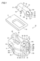
FIG. 1 is an exploded perspective view illustrating a first embodiment of a slider for slide fastener according to the invention; -
FIG. 2 is a longitudinal cross-sectional view of the slider for slide fastener shown inFIG. 1 ; -
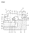
FIG. 3 is a longitudinal cross-sectional view of the slider for slide fastener shown inFIG. 2 in the state in which the cover member is pulled up by the pull-tab; -
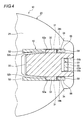
FIG. 4 is a lateral cross-sectional view taken along the portion where the latching protrusions and the latching step portions of the front-side post section are latched together; -
FIG. 5 is a longitudinal cross-sectional view illustrating the contact state between the elastic piece and the bottom surface of the elastic piece receiving portion shown inFIG. 4 ; -
FIG. 6 is a longitudinal cross-sectional view illustrating the state in which the body shown inFIG. 2 is molded with a mold; -
FIG. 7 is a cross-sectional view taken along line A-A inFIG 6 ; -
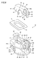
FIG. 8 is an exploded perspective view illustrating a second embodiment of the slider for slide fastener according to the invention; -
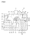
FIG. 9 is a longitudinal cross-sectional view of the slider for slide fastener shown inFIG. 8 ; -
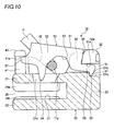
FIG. 10 is a longitudinal cross-sectional view of the slider for slide fastener shown inFIG. 9 in the state in which the cover member is pulled up by the pull-tab; -
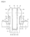
FIG. 11 is a front elevation view of the surroundings of the front-side post section of the slider for slide fastener shown inFIG. 8 ; -
FIG. 12 is a longitudinal cross-sectional view illustrating the state in which the body shown inFIG 9 is molded with a mold; -
FIG. 13 is an enlarged perspective view of key parts illustrating a modified embodiment of the slider for slide fastener of the second embodiment; -
FIG. 14 is an exploded perspective view illustrating a third embodiment of a slider for slide fastener according to the invention; -
FIG. 15 is a longitudinal view of the slider for slide fastener shown inFIG. 14 ; and -
FIG. 16 is a longitudinal view illustrating the state in which the body shown inFIG. 15 is molded with a mold. - Hereinafter, a slider for slide fastener according to each embodiment of the present invention will be described in detail with reference to the accompanying drawings. In the following description, an upper side refers to an upper side with respect to the paper surface of
FIG. 2 , a lower side refers to a lower side with respect to the paper surface ofFIG. 2 , a front side refers to a right side with respect to the paper surface ofFIG. 2 , a rear side refers to a left side with respect to the paper surface ofFIG. 2 , a right side refers to a near side with respect to the paper surface ofFIG. 2 , and a left side refers to a depth side with respect to the paper surface ofFIG. 2 . In addition, the left-right direction of the slider is also referred to as a lateral direction. - A first embodiment of the slide fastener according to the present invention will be described first with reference to
FIG. 1 to FIG 7 . - The slider for
slide fastener 10 according to this embodiment is a slider having an automatic stop function. As shown inFIG. 1 andFIG. 2 , theslider 10 has abody 20 which has anelement guide path 27 which extends through the inside of thebody 20 in the front-rear direction. Describing in detail, thebody 20 includes upper andlower blades guide post 23 which connects the front end portion of theupper blade 21 to the front end portion of thelower blade 22,upper flanges 24a which protrude downward along right and left side edges of theupper blade 21, andlower flanges 24b which protrude upward along right and left side edges of thelower blade 22. Due to this, right andleft shoulder mouths 25 which are divided by theguide post 23 are formed in the front portion of thebody 20, and arear mouth 26 is formed in the rear portion of thebody 20. In addition, a substantially Y-shapedelement guide path 27 which allows the right andleft shoulder mouths 25 and therear mouth 26 to communicate with each other is formed between the upper andlower blades element guide path 27 forms a passage through which fastener element rows (not shown) are inserted. - A front-
side post section 30 and a rear-side post section 40 are respectively erected on the front end portion and the rear end portion of the upper surface of theupper blade 21. Acover member 50 is supported on the front-side post section 30 and the rear-side post section 40 so as to rock in the upward and downward direction. In addition, in theslider 10 according to this embodiment, after ashaft portion 11a of a pull-tab 11 is set between the front-side post section 30 and the rear-side post section 40 of thebody 20, when thecover member 50 is fitted around the front-side post section 30 and the rear-side post section 40, theshaft portion 11a of the pull-tab 11 is covered from above by thecover member 50 and is situated between the upper surface of theupper blade 21 and thecover member 50. Consequently, the pull-tab 11 is attached to thebody 20. - The
cover member 50 is made by bending one sheet of plate member, and as shown inFIG. 1 andFIG. 2 , has arectangular top plate 51 which extends in the front-rear direction and a pair of right andleft side plates 52 which extend downward from both side edges of thetop plate 51. Thecover member 50 also has pull-tab receiving recesses 53, ahook 54 and anelastic piece 55. The pull-tab receiving recesses 53 are respectively formed in the pair of right and leftside plates 52, are recessed upward, and receive theshaft portion 11a of the pull-tab 11. Thehook 54 extends downward from the portion of theright side plate 52 that is behind the pull-tab receiving recesses 53, and enters theelement guide path 27 through thehook hole 21a formed in theupper blade 21. Theelastic piece 55 extends forward from the front end portion of thetop plate 51, the leading end of theelastic piece 55 being bent downward, and urges thecover member 50 so that thehook 54 enters theelement guide path 27. In addition, thecover member 50 also has a pair of right and left front-side engagement pieces 56 and a pair of right and left rear-side engagement pieces 57. The pair of right and left front-side engagement pieces 56 respectively extend forward from the front end portions of the pair of right and leftside plates 52, and engage with the front-side post section 30. The pair of right and left rear-side engagement pieces 57 respectively extend rearward from the rear end portions of the pair of right and leftside plates 52, and engage with the rear-side post section 40. In addition, thehook hole 21a extends in a penetrating fashion from the upper surface of theupper blade 21 to theelement guide path 27. In addition, theelastic piece 55 urges thecover member 50 rearward and downward through contact with an elasticpiece receiving portion 33 which will be described later. - Front-side engagement recesses 31 with which the pair of right and left front-
side engagement pieces 56 of thecover member 50 engage are respectively formed in right and left side surfaces of the front-side post section 30. The front-side engagement recess 31 in the left side surface of the front-side post section 30 is opened to the left of thebody 20, and the front-side engagement recess 31 in the right side surface of the front-side post section 30 is opened to the right of thebody 20. In addition, since the front-side engagement recesses 31 are respectively formed in a penetrating fashion in the front-rear direction of thebody 20, the front-side engagement recesses 31 are respectively opened in the front-rear direction of thebody 20. In addition, the upper surfaces of the front-side engagement recesses 31 respectively formengagement surfaces 31a. The engagement surfaces 31a are the surfaces that respectively face theupper surfaces 56a of the front-side engagement pieces 56, and abut to theupper surfaces 56a of the front-side engagement pieces 56 so as to prevent thecover member 50 from moving upward. - In addition,
protrusions 32 which protrude outward in the lateral direction of thebody 20 are respectively formed on the front end sides of the front-side post section 30 that are also the upper ends of the right and left side surfaces of the front-side post section 30. The outer surfaces of theprotrusions 32 form slope surfaces 32a which are inclined downward to the bottom from the upper end the front-side post section 30. When thecover member 50 is fitted around the front-side post section 30, the pair of right and left front-side engagement pieces 56 climb on the slope surfaces 32a. In addition, theprotrusions 32 are configured such that their thickness in the lateral direction gradually increases in the direction from the upper end to the bottom of the front-side post section 30 in order to form the engagement surfaces 31a of the front-side engagement recesses 31. - In addition, the front surfaces of the right and left
protrusions 32 are surfaces that continue from the front surface of the front-side post section 30. In addition, therear surfaces 32b of theprotrusions 32 and the front end surfaces 52a of the right and leftside plates 52 of thecover member 50 face each other in the front-rear direction of thebody 20. Furthermore, thecover member 50 is prevented from moving forward through contact between the rear surfaces of theprotrusions 32 and the front end surfaces 52a of theside plates 52. - In addition, an elastic
piece receiving portion 33 is formed in the front surface of the front-side post section 30. The elasticpiece receiving portion 33 extends forward and downward from the upper end portion of the front-side post section 33 to the front surface of theguide post 23, receives theelastic piece 55 of thecover member 50, and has a concave shape that is opened forward. The elasticpiece receiving portion 33 has abottom surface 33a, a pair of right and left side surfaces 33b which extend forward from right and left end edges of thebottom surface 33a, and alower end surface 33c which extends forward from the lower end edge of thebottom surface 33a. - In addition, when the
cover member 50 is fitted around the front-side post section 30, as shown inFIG. 4 andFIG. 5 , the front end surfaces 52a of the right and leftside plates 52 come into contact with therear surfaces 32b of the right and leftprotrusions 32, and concurrently, theelastic piece 55 comes into contact with thebottom surface 33a of the elasticpiece receiving portion 33. Consequently, the front-side post section 30 is sandwiched in the front-rear direction by the front end surfaces 52a of the right and leftside plates 52 and theelastic piece 55, so that the place where thecover member 50 is attached to the body 20 (front-side post section 30) is positioned. - In addition, also in this embodiment, as shown in
FIG. 1 ,FIG. 2 andFIG 4 , latchingstep portions 34 which are recessed upward are respectively formed in the front portions of the engagement surfaces 31a of the right and left front-side engagement recesses 31, and latchingprotrusions 58 are respectively formed on the upper surfaces of the front ends of the pair of right and left front-side engagement pieces 56. The latchingprotrusions 58 protrude upward so as to latch to the latchingstep portions 34. - Each of the latching
step portions 34 has anengagement surface 34a and astopper surface 34b. Theengagement surface 34a faces a corresponding upper surface of the latchingprotrusions 58. Thestopper surface 34b is the surface that faces a corresponding rear surface of the latchingprotrusions 58, and abuts to the rear surface of the latchingprotrusions 58 so as to prevent thecover member 50 from moving rearward. In addition, the surfaces engagement is not the surface that engages with acorresponding latching protrusion 58 but is configured so as to avoid contact (interference) with the latchingprotrusion 58. In addition, as shown inFIG. 3 , when thecover member 50 is pulled up by the pull-tab 11, thecover member 50 rotates about the points of contact between the front end surfaces 52a of the right and leftside plates 52 and therear surfaces 32b of the right and leftprotrusions 32 of the front-side post section 30. In addition, since the front end portions of the latchingstep portions 34 are opened forward, they can be formed by a slide core K3 which moves in the front-rear direction of the body 20 (seeFIG. 6 ). - In addition, as shown in
FIG. 2 , the upper surfaces of the front-side engagement pieces 56 are formed as inclined surfaces that are inclined downward from the leading end side to the base end side. Therefore, when thecover member 50 is attached to thebody 20, the engagement surfaces 31a of the front-side engagement recesses 31 are horizontal surfaces that are parallel to the front-rear direction of thebody 20, whereas theupper surfaces 56a of the front-side engagement pieces 56 are inclined downward in the direction from the front side to the rear side of thebody 20. That is, the gaps between the engagement surfaces 31a of the front-side engagement recesses 31 and theupper surfaces 56a of the front-side engagement pieces 56 gradually increase in the direction from the front side to the rear side of thebody 20. Due to this, when thecover member 50 rotates, the front-side engagement pieces 56 move upward while reducing the gaps between the engagement surfaces 31a and theupper surfaces 56a of the front-side engagement pieces 56. Consequently, the front-side engagement pieces 56 do not interfere with theengagement surfaces 31a. - Rear-side engagement recesses 41 are respectively formed on the right and left side surfaces of the rear-
side post section 40. The pair of right and left rear-side engagement pieces 57 of thecover member 50 engage with the rear-side engagement recesses 41. The rear-side engagement recess 41 in the left side surface of the rear-side post section 40 is opened to the left of thebody 20, and the rear-side engagement recess 41 in the right side surface of the rear-side post section 40 is opened to the right of thebody 20. In addition, since the rear-side engagement recesses 41 are respectively formed in a penetrating fashion in the front-rear direction of thebody 20, the rear-side engagement recesses 41 are respectively opened in the front-rear direction of thebody 20. In addition, the upper surfaces of the rear-side engagement recesses 41 respectively formengagement surfaces 41a. The engagement surfaces 41a are the surfaces that respectively face the upper surfaces of the rear-side engagement pieces 57, and abut to the upper surfaces of the front-side engagement pieces 57 so as to prevent thecover member 50 from moving upward. - In addition, a
guide portion 42 is formed on the left end of the front surface of the rear-side post section 40 so as to extend forward, and has a triangular shape when viewed from the side. When the pull-tab 11 is pulled up, theguide portion 42 allows theshaft portion 11a of the pull-tab 11 to climb thereon and guides the movement (upward movement) of theshaft portion 11a. Theguide portion 42 serves to move thecover member 50 upward by guiding the movement of theshaft portion 11 a. - In the slider for
slide fastener 10 as configured above, as shown inFIG. 6 andFIG. 7 , it is possible to produce a plurality ofbodies 20 in which the front-side and rear-side engagement recesses 31 and 41 and the latchingstep portions 34 are formed in a single casting process using an upper mold K1, a lower mold (not shown) and front and rear slide cores K3 and K4 which move in the front-rear direction of thebody 20. In addition, since the latchingprotrusions 58 of thecover member 50 are latched to the latchingstep portions 34 of the front-side post section 30, thecover member 50 is prevented from moving rearward. - In addition, the upper mold K1 and the front and rear slide cores K3 and K4 cooperate to mold the front-
side post section 30 and rear-side post section 40 provided on the upper surface of thebody 20. The front and rear slide cores K3 and K4 can move toward and away from each other along the lower surface of the upper mold K1. The front and rear slide cores K3 and K4 move toward each other when thebody 20 is being molded. After thebody 20 is molded, the front and rear slide cores K3 and K4 move away from each other. The front slide core K3 has a first molding recess K31 in the leading end thereof, and a portion of the front surface of the front-side post section 30, a portion of the left surface of the front-side post section 30 and a portion of the right surface of the front-side post section 30 are molded in the first molding recess K31 (seeFIG. 7 ). The rear slide core K4 has a second molding recess K41 in the leading end thereof, and a portion of the rear surface of the rear-side post section 40, a portion of the left surface of the rear-side post section 40 and a portion of the right surface of the rear-side post section 40 are molded in the rear slide core K4 (seeFIG. 7 ). In addition, the front slide core K3 has a step portion K32 on the upper surface of the leading end portion, the step portion K32 being recessed downward (seeFIG. 6 ). Due to this, the engagement surfaces 34a of the latchingstep portions 34 are molded in the upper surface of the slide core K3, and the engagement surfaces 31 a of the front-side engagement recesses 31 and the stopper surfaces 34b of the latchingstep portions 34 are molded in the step portion K32. In addition, theguide portion 42 and thehook hole 21a are molded by the upper mold K1 alone. - As described above, in the slider for
slide fastener 10 according to this embodiment, since the front-side and rear-side engagement recesses 31 and 41 are formed to penetrate through thebody 20 in the front-rear direction, the front-side and rear-side engagement recesses 31 and 41 can be formed using the slide core which moves in the front-rear direction of thebody 20. It is therefore possible to preclude the slide core which moves in the lateral direction of thebody 20 and with which the front-side and rear-side engagement recesses 31 and 41 are formed. Due to this, a plurality ofbodies 20 can be produced in a single casting process, thereby reducing the manufacturing cost of theslider 10. - In addition, in the slider for
slide fastener 10 according to this embodiment, the latchingstep portions 34 are respectively formed on the right and left surfaces of the front-side post section 30, and the latchingprotrusions 58 which are latched to the latchingstep portions 34 are respectively formed on the pair of right and left front-side engagement pieces 56. Thus, it is possible to prevent thecover member 50 from moving rearward through latching between the latchingstep portions 34 and the latchingprotrusions 58. This can consequently prevent metal fatigue in theelastic piece 55 of thecover member 50. - Next, with reference to
FIG. 8 to FIG. 13 , a description will be given below of a second embodiment of the slider for slide fastener according to the invention. In addition, the same reference numerals and signs will be used in the drawings in order to designate some components when they are the same as or similar to those of the first embodiment, and descriptions of those components will be omitted or simplified. - In this embodiment, as shown in
FIG. 8 ,FIG. 9 andFIG. 11 , instead of the latchingstep portions 34 and the latchingprotrusions 58 of the first embodiment, latchingstep portions 61 which are recessed downward are respectively formed in theupper blade 21 which forms the lower surfaces of the right and left front-side engagement recesses 31 and latchingprotrusions 62 which protrude downward are respectively formed on the lower surfaces of the front ends of the pair of right and left front-side engagement pieces 56. The latchingprotrusions 62 are latched to the latchingstep portions 61. - The front-side engagement recesses 31 with which the pair of right and left front-
side engagement pieces 56 of thecover member 50 engage are respectively formed on the right and left side surfaces of the front-side post section 30. The front-side engagement recesses 31 on the left side surface of the front-side post section 30 are opened to the left of thebody 20, and the front-side engagement recesses 31 on the right side surface of the front-side post section 30 are opened to the right of thebody 20. In addition, since the front-side engagement recesses 31 are respectively formed in a penetrating fashion in the front-rear direction of thebody 20, the front-side engagement recesses 31 are respectively opened in the front-rear direction of thebody 20. In addition, the upper surfaces of the front-side engagement recesses 31 respectively formengagement surfaces 31a. The engagement surfaces 31 a are the surfaces that respectively face theupper surfaces 56a of the front-side engagement pieces 56, and abut to theupper surfaces 56a of the front-side engagement pieces 56 so as to prevent thecover member 50 from moving upward. - Each of the latching
step portions 61 has abottom surface 61a and astopper surface 61b. Thebottom surface 61a is the surface that faces a corresponding lower surface of the latchingprotrusions 62. Thestopper surface 61b is the surface that faces a corresponding rear surface of the latchingprotrusions 62, and abuts to the rear surface of the latching protrusions 62so as to prevent thecover member 50 from moving rearward. In addition, as shown inFIG. 10 , when thecover member 50 is pulled up by the pull-tab 11, thecover member 50 rotates about the points of contact between the front end surfaces 52a of the right and leftside plates 52 and therear surfaces 32b of the right and leftprotrusions 32 of the front-side post section 30. In addition, although there are gaps between the latchingprotrusions 62 and the stopper surfaces 61 b before rotation of thecover member 50, the latchingprotrusions 62 approach and abut to the stopper surfaces 61b when thecover member 50 rotates upward. In addition, since the front end portions of the latchingstep potions 61 are opened forward, they can be formed by a slide core K3 which moves in the front-rear direction of the body 20 (seeFIG. 12 ). - In the slider for
slide fastener 10 as configured above, as shown inFIG. 12 , it is possible to produce a plurality ofbodies 20 in which the front-side and rear-side engagement recesses 31 and 41 and the latchingstep portions 34 are formed in a single casting process using an upper mold K1, a lower mold (not shown) and front and rear slide cores K3 and K4 which move in the front-rear direction of thebody 20. In addition, since the latchingprotrusions 62 of thecover member 50 are latched to the latchingstep portions 61 of the front-side post section 30, thecover member 50 is prevented from moving rearward. - In addition, the upper mold K1 and the front and rear slide cores K3 and K4 cooperate to mold the front-
side post section 30 and rear-side post section 40 provided on the upper surface of thebody 20. The front and rear slide cores K3 and K4 can move toward and away from each other along the lower surface of the upper mold K1. The front and rear slide cores K3 and K4 move toward each other when thebody 20 is being molded. After thebody 20 is molded, the front and rear slide cores K3 and K4 move away from each other. In addition, the front slide core K3 has an upwardly-recessed step portion K32 in the lower surface of the leading end portion (seeFIG. 12 ). Due to this, the bottom surfaces 61a of the latchingstep portions 61 are molded in the lower surface of the slide core K3, and the lower surfaces of the front-side engagement recesses 31 and the stopper surfaces 61b of the latchingstep portions 61 are molded in the step portion K32. In addition, theguide portion 42 and thehook hole 21a are molded by the upper mold K1 alone. - As described above, in the slider for
slide fastener 10 according to this embodiment, the latchingstep portions 61 are respectively formed on theupper blade 21 which forms the lower surface of the right and left front-side engagement recesses 31, and the latching protrusions which are latched to the latchingstep portions 61 are respectively formed on the pair of right and left front-side engagement pieces 56. Thus, it is possible to prevent thecover member 50 from moving rearward through latching between the latchingstep portions 61 and the latchingprotrusions 52. This can consequently prevent metal fatigue in theelastic piece 55 of thecover member 50. - The other configurations, operations and effects are the same as those of the first embodiment.
- In addition, according to a modified embodiment of this embodiment, as shown in
FIG. 13 , the latchingstep portions 61 may be formed in a penetrating fashion not only at the position adjacent to the side surfaces of the front-side post section 30 but also outward in the lateral direction of theupper blade 21. Therefore, in this case, the latchingstep portions 61 are opened forward and outward. - Next, with reference to
FIG. 14 to FIG. 16 , a description will be given below of a third embodiment of the slider for slide fastener according to the invention. - The slider for
slide fastener 10 according to this embodiment is a slider having an automatic stop function. As shown inFIG. 14 andFIG. 15 , theslider 10 has abody 20 which has anelement guide path 27 which extends through the inside of thebody 20 in the front-rear direction. Describing in detail, thebody 20 includes upper andlower blades guide post 23 which connects the front end portion of theupper blade 21 to the front end portion of thelower blade 22,upper flanges 24a which protrude downward along right and left side edges of theupper blade 21, andlower flanges 24b which protrude upward along right and left side edges of thelower blade 22. Due to this, right andleft shoulder mouths 25 which are divided by theguide post 23 are formed in the front portion of thebody 20, and arear mouth 26 is formed in the rear portion of thebody 20. In addition, a substantially Y-shapedelement guide path 27 which allows the right andleft shoulder mouths 25 and therear mouth 26 to communicate with each other is formed between the upper andlower blades element guide path 27 forms a passage through which fastener element rows (not shown) are inserted. - A front-
side post section 30 and a rear-side post section 40 are respectively erected on the front end portion and the rear end portion of the upper surface of theupper blade 21. Acover member 50 is supported on the front-side post section 30 and the rear-side post section 40 so as to rock in the upward and downward direction. In addition, in theslider 10 according to this embodiment, after ashaft portion 11a of a pull-tab 11 is set between the front-side post section 30 and the rear-side post section 40 of thebody 20, when thecover member 50 is fitted around the front-side post section 30 and the rear-side post section 40, theshaft portion 11a of the pull-tab 11 is covered from above by thecover member 50 and is situated between the upper surface of theupper blade 21 and thecover member 50. Consequently, the pull-tab 11 is attached to thebody 20. - The
cover member 50 is made by bending one sheet of plate member, and as shown inFIG. 14 andFIG. 15 , has a rectangulartop plate 51 which extends in the front-rear direction and a pair of right and leftside plates 52 which extend downward from both side edges of thetop plate 51. Thecover member 50 also has pull-tab receiving recesses 53, ahook 54 and anelastic piece 55. The pull-tab receiving recesses 53 are respectively formed in the pair of right and leftside plates 52, are recessed upward, and receive theshaft portion 11a of the pull-tab 11. Thehook 54 extends downward from the portion of theright side plate 52 that is behind the pull-tab receiving recesses 53, and enters theelement guide path 27 through thehook hole 21a formed in theupper blade 21. Theelastic piece 55 extends forward from the front end portion of thetop plate 51, the leading end of theelastic piece 55 being bent downward, and urges thecover member 50 so that thehook 54 enters theelement guide path 27. In addition, thecover member 50 also has a pair of right and left front-side engagement pieces 56 and a pair of right and left rear-side engagement pieces 57. The pair of right and left front-side engagement pieces 56 respectively extend forward from the front end portions of the pair of right and leftside plates 52, and engage with the front-side post section 30. The pair of right and left rear-side engagement pieces 57 respectively extend rearward from the rear end portions of the pair of right and leftside plates 52, and engage with the rear-side post section 40. In addition, thehook hole 21a extends in a penetrating fashion from the upper surface of theupper blade 21 to theelement guide path 27. In addition, theelastic piece 55 urges thecover member 50 rearward and downward through contact with an elasticpiece receiving portion 33 which will be described later. - Front-side engagement recesses 31 with which the pair of right and left front-
side engagement pieces 56 of thecover member 50 engage are respectively formed in right and left side surfaces of the front-side post section 30. The front-side engagement recess 31 in the left side surface of the front-side post section 30 is opened to the left of thebody 20, and the front-side engagement recess 31 in the right side surface of the front-side post section 30 is opened to the right of thebody 20. In addition, since the front-side engagement recesses 31 are formed in a penetrating fashion in the front-rear direction of thebody 20, the front-side engagement recesses 31 are respectively opened in the front-rear direction of thebody 20. In addition, the upper surfaces of the front-side engagement recesses 31 respectively formengagement surfaces 31a. The engagement surfaces 31a are the surfaces that respectively face theupper surfaces 56a of the front-side engagement pieces 56, and abut to theupper surfaces 56a of the front-side engagement pieces 56 so as to prevent thecover member 50 from moving upward. - In addition,
protrusions 32 which protrude outward in the lateral direction of thebody 20 are respectively formed on the front end sides of the front-side post section 30 that are also the upper ends of the right and left side surfaces of the front-side post section 30. The outer surfaces of theprotrusions 32 form slope surfaces 32a which are inclined downward to the bottom from the upper end the front-side post section 30. When thecover member 50 is fitted around the front-side post section 30, the pair of right and left front-side engagement pieces 56 climb on the slope surfaces 32a. In addition, theprotrusions 32 are configured such that their thickness in the lateral direction gradually increases in the direction from the upper end to the bottom of the front-side post section 30 in order to form the engagement surfaces 31a of the front-side engagement recesses 31. - In addition, the front surfaces of the right and left
protrusions 32 are surfaces that continue from the front surface of the front-side post section 30. In addition, therear surfaces 32b of theprotrusions 32 and the front end surfaces 52a of the right and leftside plates 52 of thecover member 50 face each other in the front-rear direction of thebody 20. Furthermore, thecover member 50 is prevented from moving forward through contact between the rear surfaces of theprotrusions 32 and the front end surfaces 52a of theside plates 52. - In addition, an elastic
piece receiving portion 33 is formed in the front surface of the front-side post section 30. The elasticpiece receiving portion 33 extends forward and downward from the upper end portion of the front-side post section 33 to the front surface of theguide post 23, receives theelastic piece 55 of thecover member 50, and has a concave shape that is opened forward. The elasticpiece receiving portion 33 has abottom surface 33a, a pair of right and left side surfaces 33b which extend forward from right and left end edges of thebottom surface 33a, and alower end surface 33c which extends forward from the lower end edge of thebottom surface 33a. - In addition, when the
cover member 50 is fitted around the front-side post section 30, the front end surfaces 52a of the right and leftside plates 52 come into contact with therear surfaces 32b of the right and leftprotrusions 32, and concurrently, theelastic piece 55 comes into contact with thebottom surface 33a of the elasticpiece receiving portion 33. Consequently, the front-side post section 30 is sandwiched in the front-rear direction by the front end surfaces 52a of the right and leftside plates 52 and theelastic piece 55, so that the place where thecover member 50 is attached to the body 20 (front-side post section 30) is positioned. - In addition, as shown in
FIG. 15 , theupper surfaces 56a of the front-side engagement pieces 56 are formed as inclined surfaces that are inclined downward from the leading end side to the base end side. Therefore, when thecover member 50 is attached to thebody 20, the engagement surfaces 31a of the front-side engagement recesses 31 are horizontal surfaces that are parallel to the front-rear direction of thebody 20, whereas theupper surfaces 56a of the front-side engagement pieces 56 are inclined downward in the direction from the front side to the rear side of thebody 20. That is, the gaps between the engagement surfaces 31a of the front-side engagement recesses 31 and theupper surfaces 56a of the front-side engagement pieces 56 gradually increase in the direction from the front side to the rear side of thebody 20. Due to this, when thecover member 50 rotates, the front-side engagement pieces 56 move upward while reducing the gaps between the engagement surfaces 31a and theupper surfaces 56a of the front-side engagement pieces 56. Consequently, the front-side engagement pieces 56 do not interfere with theengagement surfaces 31a. - Rear-side engagement recesses 41 are respectively formed on the right and left side surfaces of the rear-
side post section 40. The pair of right and left rear-side engagement pieces 57 of thecover member 50 engage with the rear-side engagement recesses 41. The rear-side engagement recess 41 in the left side surface of the rear-side post section 40 is opened to the left of thebody 20, and the rear-side engagement recess 41 in the right side surface of the rear-side post section 40 is opened to the right of thebody 20. In addition, since the rear-side engagement recesses 41 are respectively formed in a penetrating fashion in the front-rear direction of thebody 20, the rear-side engagement recesses 41 are respectively opened in the front-rear direction of thebody 20. In addition, the upper surfaces of the rear-side engagement recesses 41 respectively formengagement surfaces 41a. The engagement surfaces 41 a are the surfaces that respectively face the upper surfaces of the rear-side engagement pieces 57, and abut to the upper surfaces of the front-side engagement pieces 57 so as to prevent thecover member 50 from moving upward. - In addition, a
guide portion 42 is formed on the left end of the front surface of the rear-side post section 40 so as to extend forward, and has a triangular shape when viewed from the side. When the pull-tab 11 is pulled up, theguide portion 42 allows theshaft portion 11a of the pull-tab 11 to climb thereon and guides the movement (upward movement) of theshaft portion 11a. Theguide portion 42 serves to move thecover member 50 upward by guiding the movement of theshaft portion 11a. - In the slider for
slide fastener 10 as configured above, as shown inFIG. 16 , it is possible to produce a plurality ofbodies 20 in which the front-side and rear-side engagement recesses 31 and 41 are formed in a single casting process using an upper mold K1, a lower mold (not shown) and front and rear slide cores K3 and K4 which move in the front-rear direction of thebody 20. - In addition, the upper mold K1 and the front and rear slide cores K3 and K4 cooperate to mold the front-
side post section 30 and rear-side post section 40 provided on the upper surface of thebody 20. The front and rear slide cores K3 and K4 can move toward and away from each other along the lower surface of the upper mold K1. The front and rear slide cores K3 and K4 move toward each other when thebody 20 is being molded. After thebody 20 is molded, the front and rear slide cores K3 and K4 move away from each other. - As described above, in the slider for
slide fastener 10 according to this embodiment, since the front-side and rear-side engagement recesses 31 and 41 are formed to penetrate through thebody 20 in the front-rear direction, the front-side and rear-side engagement recesses 31 and 41 can be formed using the slide core which moves in the front-rear direction of thebody 20. It is therefore possible to preclude the slide core which moves in the lateral direction of thebody 20 and with which the front-side and rear-side engagement recesses 31 and 41 are formed. Due to this, a plurality ofbodies 20 can be produced in a single casting process, thereby reducing the manufacturing cost of theslider 10. - The present invention is not limited to the foregoing embodiments and can be properly modified without departing from the scope of the present invention.
-
- 10
- Slider For Slide Fastener
- 11
- Pull-Tab
- 11a
- Shaft Portion
- 20
- Body
- 21
- Upper Blade
- 21a
- Hook Hole
- 27
- Element Guide Path
- 30
- Front-Side Post Section
- 31
- Front-Side Engagement Recess
- 31a
- Engagement Surface
- 32
- Protrusion
- 32b
- Rear Surface
- 33
- Elastic Piece Receiving Portion
- 32a
- Bottom Surface
- 34
- Latching Step Portion
- 34a
- Engagement Surface
- 34b
- Stopper Surface
- 40
- Rear-Side Post Section
- 41
- Rear-Side Engagement Recess
- 41a
- Engagement Surface
- 50
- Cover Member
- 51
- Top Plate
- 52
- Side Plate
- 52a
- Front End Surface
- 53
- Pull-Tab Receiving Recess
- 54
- Hook
- 55
- Elastic Piece
- 56
- Front-Side Engagement Piece
- 57
- Rear-Side Engagement Piece
- 58
- Latching Protrusion
- 61
- Latching Step Portion
- 61a
- Bottom Surface
- 61b
- Stopper Surface
- 62
- Latching Protrusion
Claims (5)
- A slider for slide fastener comprising:a body (20); anda cover member (50) supported on a front-side post section (30) and a rear-side post section (40) which are erected on an upper surface of the body,wherein the cover member comprises:a top plate (51);a pair of right and left side plates (52) which extend downward from both side edges of the top plate;pull-tab receiving recesses (53) which are respectively formed in the pair of right and left side plates and receive a shaft portion (11a) of a pull-tab (11);a hook (54) which enters an element guide path of the body through a hook hole (2 1 a) formed in the body;an elastic piece (55) which extends forward from a front end portion of the top plate, a leading end of the elastic piece being bent downward;a pair of right and left front-side engagement pieces (56) which respectively extend forward from front end portions of the pair of right and left side plates and engage with the front-side post section;a pair of right and left rear-side engagement pieces (57) which extend rearward from rear end portions of the pair of right and left side plates and engage with the rear-side post section;a concavely-shaped elastic piece receiving portion (33) which is formed in a front surface of the front-side post section, the elastic piece receiving portion receiving the elastic piece;front-side engagement recesses (31) which are respectively formed in right and left side surfaces of the front-side post section, the front-side engagement recesses having surfaces (31a) which face upper surfaces of the front-side engagement pieces; andrear-side engagement recesses (41) which are respectively formed in right and left side surfaces of the rear-side post section, the rear-side engagement recesses having surfaces (41a) which face upper surfaces of the rear-side engagement pieces, andwherein the front-side and rear-side engagement recesses are formed so as to penetrate in a front-rear direction of the body.
- The slider for slide fastener according to claim 1,
wherein protrusions (32) which protrude outward in a lateral direction of the body (20) are respectively formed on right and left side surfaces of the front-side post section (30), and
wherein front end surfaces (52a) of the pair of right and left side plates (52) of the cover member (50) come into contact with rear surfaces (32b) of the protrusions, and the elastic piece (55) comes into contact with the elastic piece receiving portion (33). - The slider for slide fastener according to claim 1 or 2,
wherein a pair of right and left latching step portions (34 and 61) are formed on the body (20), and
wherein latching protrusions (58, 62) which are latched to the latching step portions are respectively formed on the pair of right and left front-side engagement piece (56). - The slider for slide fastener according to claim 3,
wherein the latching step portions (34) which are upwardly-recessed are formed on right and left side surfaces of the front-side post section (30), and
wherein the latching protrusions (58) which protrude upward and are latched to the latching step portions are respectively formed on the pair of right and left front-side engagement pieces (56). - The slider for slide fastener according to claim 3,
wherein the body (20) has an upper blade (21) and a lower blade (22) which are arranged in parallel so as to be spaced apart from each other in an upward and downward direction and a guide post (23) which connects a front end portion of the upper blade to a front end portion of the lower blade,
wherein the pair of right and left latching step portions (61) which are downwardly-recessed are formed in the upper blade, and
wherein the latching protrusions (62) which protrude downward and are latched to the latching step portions are respectively formed on the pair of right and left front-side engagement pieces (56).
Applications Claiming Priority (1)
| Application Number | Priority Date | Filing Date | Title |
|---|---|---|---|
| PCT/JP2011/069651 WO2013030961A1 (en) | 2011-08-30 | 2011-08-30 | Slider for slide fastener |
Publications (3)
| Publication Number | Publication Date |
|---|---|
| EP2752126A1 true EP2752126A1 (en) | 2014-07-09 |
| EP2752126A4 EP2752126A4 (en) | 2015-05-20 |
| EP2752126B1 EP2752126B1 (en) | 2015-11-25 |
Family
ID=47755514
Family Applications (1)
| Application Number | Title | Priority Date | Filing Date |
|---|---|---|---|
| EP11871420.3A Active EP2752126B1 (en) | 2011-08-30 | 2011-08-30 | Slider for slide fastener |
Country Status (5)
| Country | Link |
|---|---|
| EP (1) | EP2752126B1 (en) |
| CN (1) | CN103763968B (en) |
| ES (1) | ES2558114T3 (en) |
| TW (1) | TWI465206B (en) |
| WO (1) | WO2013030961A1 (en) |
Cited By (1)
| Publication number | Priority date | Publication date | Assignee | Title |
|---|---|---|---|---|
| EP3871553A1 (en) * | 2020-02-28 | 2021-09-01 | Riri S.A. | Slider for a slide fastener |
Families Citing this family (2)
| Publication number | Priority date | Publication date | Assignee | Title |
|---|---|---|---|---|
| TWI592107B (en) * | 2015-11-30 | 2017-07-21 | 中傳企業股份有限公司 | Zipper head assembly structure for decreasing assembling resistance and movable cover body thereof |
| IT201800004992A1 (en) * | 2018-05-02 | 2019-11-02 | Zipper slider. |
Family Cites Families (6)
| Publication number | Priority date | Publication date | Assignee | Title |
|---|---|---|---|---|
| GB644482A (en) * | 1948-05-07 | 1950-10-11 | Aero Zipp Fasteners Ltd | Improvements in or relating to sliding clasp fasteners |
| GB982828A (en) * | 1963-12-18 | 1965-02-10 | Aero Zipp Fasteners Ltd | Improvements in or relating to sliding clasp fasteners |
| US3427692A (en) * | 1968-02-19 | 1969-02-18 | Scovill Manufacturing Co | Three-piece automatic lock slider |
| JPH0721123Y2 (en) * | 1988-10-22 | 1995-05-17 | ワイケイケイ株式会社 | Slider for slide fastener with automatic stop device |
| JP4628227B2 (en) * | 2005-09-12 | 2011-02-09 | Ykk株式会社 | Slider for slide fastener with automatic stop device |
| JP4632924B2 (en) * | 2005-10-21 | 2011-02-16 | Ykk株式会社 | Slider for slide fastener with automatic stop device |
-
2011
- 2011-08-30 CN CN201180073126.6A patent/CN103763968B/en active Active
- 2011-08-30 ES ES11871420.3T patent/ES2558114T3/en active Active
- 2011-08-30 WO PCT/JP2011/069651 patent/WO2013030961A1/en not_active Ceased
- 2011-08-30 EP EP11871420.3A patent/EP2752126B1/en active Active
-
2012
- 2012-08-14 TW TW101129414A patent/TWI465206B/en active
Cited By (2)
| Publication number | Priority date | Publication date | Assignee | Title |
|---|---|---|---|---|
| EP3871553A1 (en) * | 2020-02-28 | 2021-09-01 | Riri S.A. | Slider for a slide fastener |
| US11324291B2 (en) | 2020-02-28 | 2022-05-10 | Riri Sa | Slider for a slide fastener |
Also Published As
| Publication number | Publication date |
|---|---|
| CN103763968B (en) | 2016-10-26 |
| ES2558114T3 (en) | 2016-02-02 |
| TWI465206B (en) | 2014-12-21 |
| WO2013030961A1 (en) | 2013-03-07 |
| EP2752126A4 (en) | 2015-05-20 |
| EP2752126B1 (en) | 2015-11-25 |
| CN103763968A (en) | 2014-04-30 |
| TW201311171A (en) | 2013-03-16 |
Similar Documents
| Publication | Publication Date | Title |
|---|---|---|
| EP2412265B1 (en) | Slide fastener with separable bottom end stop | |
| EP2752126B1 (en) | Slider for slide fastener | |
| JP2012091597A (en) | Mounting structure of onboard camera | |
| EP2604138A1 (en) | Slide fastener | |
| US8991017B2 (en) | Slider for slide fastener | |
| JPWO2016027340A1 (en) | Slider for slide fastener | |
| KR100933545B1 (en) | Mold Assembly | |
| CN107518534A (en) | The pull head lid and pull head group of slide fastener | |
| KR20100123511A (en) | Mold assembly for insert mold | |
| CN103763969B (en) | Slider for slide fastener | |
| EP2737817A1 (en) | Slider for slide fastener | |
| JP2005174697A (en) | Connector and connector manufacturing method | |
| CN107205527B (en) | zipper puller | |
| KR102189452B1 (en) | Slider and slide fastener | |
| CN115768302A (en) | slider | |
| CN105163621B (en) | Slider for zipper and its design method | |
| US20240186727A1 (en) | Terminal block | |
| TW201330796A (en) | Sliding fastener slider | |
| JP5462978B2 (en) | Slider for slide fastener | |
| JP5590386B2 (en) | Connector and connector manufacturing method | |
| CN103517651A (en) | Slider for slide fastener | |
| CN206568890U (en) | Novel disconnect-type accelerator pedal body | |
| WO2013030962A1 (en) | Slider for slide fastener | |
| JP2009140809A (en) | Joint connector | |
| HK1154466A1 (en) | Slider for slide fastener with automatic stopper |
Legal Events
| Date | Code | Title | Description |
|---|---|---|---|
| PUAI | Public reference made under article 153(3) epc to a published international application that has entered the european phase |
Free format text: ORIGINAL CODE: 0009012 |
|
| 17P | Request for examination filed |
Effective date: 20140227 |
|
| AK | Designated contracting states |
Kind code of ref document: A1 Designated state(s): AL AT BE BG CH CY CZ DE DK EE ES FI FR GB GR HR HU IE IS IT LI LT LU LV MC MK MT NL NO PL PT RO RS SE SI SK SM TR |
|
| DAX | Request for extension of the european patent (deleted) | ||
| RA4 | Supplementary search report drawn up and despatched (corrected) |
Effective date: 20150420 |
|
| RIC1 | Information provided on ipc code assigned before grant |
Ipc: A44B 19/30 20060101AFI20150414BHEP |
|
| GRAP | Despatch of communication of intention to grant a patent |
Free format text: ORIGINAL CODE: EPIDOSNIGR1 |
|
| INTG | Intention to grant announced |
Effective date: 20150721 |
|
| GRAS | Grant fee paid |
Free format text: ORIGINAL CODE: EPIDOSNIGR3 |
|
| GRAA | (expected) grant |
Free format text: ORIGINAL CODE: 0009210 |
|
| AK | Designated contracting states |
Kind code of ref document: B1 Designated state(s): AL AT BE BG CH CY CZ DE DK EE ES FI FR GB GR HR HU IE IS IT LI LT LU LV MC MK MT NL NO PL PT RO RS SE SI SK SM TR |
|
| REG | Reference to a national code |
Ref country code: GB Ref legal event code: FG4D |
|
| REG | Reference to a national code |
Ref country code: CH Ref legal event code: EP |
|
| REG | Reference to a national code |
Ref country code: AT Ref legal event code: REF Ref document number: 762144 Country of ref document: AT Kind code of ref document: T Effective date: 20151215 |
|
| REG | Reference to a national code |
Ref country code: IE Ref legal event code: FG4D |
|
| REG | Reference to a national code |
Ref country code: DE Ref legal event code: R096 Ref document number: 602011021739 Country of ref document: DE |
|
| REG | Reference to a national code |
Ref country code: ES Ref legal event code: FG2A Ref document number: 2558114 Country of ref document: ES Kind code of ref document: T3 Effective date: 20160202 |
|
| REG | Reference to a national code |
Ref country code: LT Ref legal event code: MG4D |
|
| REG | Reference to a national code |
Ref country code: NL Ref legal event code: MP Effective date: 20160225 |
|
| REG | Reference to a national code |
Ref country code: AT Ref legal event code: MK05 Ref document number: 762144 Country of ref document: AT Kind code of ref document: T Effective date: 20151125 |
|
| PG25 | Lapsed in a contracting state [announced via postgrant information from national office to epo] |
Ref country code: HR Free format text: LAPSE BECAUSE OF FAILURE TO SUBMIT A TRANSLATION OF THE DESCRIPTION OR TO PAY THE FEE WITHIN THE PRESCRIBED TIME-LIMIT Effective date: 20151125 Ref country code: NL Free format text: LAPSE BECAUSE OF FAILURE TO SUBMIT A TRANSLATION OF THE DESCRIPTION OR TO PAY THE FEE WITHIN THE PRESCRIBED TIME-LIMIT Effective date: 20151125 Ref country code: IS Free format text: LAPSE BECAUSE OF FAILURE TO SUBMIT A TRANSLATION OF THE DESCRIPTION OR TO PAY THE FEE WITHIN THE PRESCRIBED TIME-LIMIT Effective date: 20160325 Ref country code: NO Free format text: LAPSE BECAUSE OF FAILURE TO SUBMIT A TRANSLATION OF THE DESCRIPTION OR TO PAY THE FEE WITHIN THE PRESCRIBED TIME-LIMIT Effective date: 20160225 Ref country code: LT Free format text: LAPSE BECAUSE OF FAILURE TO SUBMIT A TRANSLATION OF THE DESCRIPTION OR TO PAY THE FEE WITHIN THE PRESCRIBED TIME-LIMIT Effective date: 20151125 |
|
| PG25 | Lapsed in a contracting state [announced via postgrant information from national office to epo] |
Ref country code: PL Free format text: LAPSE BECAUSE OF FAILURE TO SUBMIT A TRANSLATION OF THE DESCRIPTION OR TO PAY THE FEE WITHIN THE PRESCRIBED TIME-LIMIT Effective date: 20151125 Ref country code: PT Free format text: LAPSE BECAUSE OF FAILURE TO SUBMIT A TRANSLATION OF THE DESCRIPTION OR TO PAY THE FEE WITHIN THE PRESCRIBED TIME-LIMIT Effective date: 20160325 Ref country code: SE Free format text: LAPSE BECAUSE OF FAILURE TO SUBMIT A TRANSLATION OF THE DESCRIPTION OR TO PAY THE FEE WITHIN THE PRESCRIBED TIME-LIMIT Effective date: 20151125 Ref country code: FI Free format text: LAPSE BECAUSE OF FAILURE TO SUBMIT A TRANSLATION OF THE DESCRIPTION OR TO PAY THE FEE WITHIN THE PRESCRIBED TIME-LIMIT Effective date: 20151125 Ref country code: GR Free format text: LAPSE BECAUSE OF FAILURE TO SUBMIT A TRANSLATION OF THE DESCRIPTION OR TO PAY THE FEE WITHIN THE PRESCRIBED TIME-LIMIT Effective date: 20160226 Ref country code: LV Free format text: LAPSE BECAUSE OF FAILURE TO SUBMIT A TRANSLATION OF THE DESCRIPTION OR TO PAY THE FEE WITHIN THE PRESCRIBED TIME-LIMIT Effective date: 20151125 Ref country code: AT Free format text: LAPSE BECAUSE OF FAILURE TO SUBMIT A TRANSLATION OF THE DESCRIPTION OR TO PAY THE FEE WITHIN THE PRESCRIBED TIME-LIMIT Effective date: 20151125 Ref country code: RS Free format text: LAPSE BECAUSE OF FAILURE TO SUBMIT A TRANSLATION OF THE DESCRIPTION OR TO PAY THE FEE WITHIN THE PRESCRIBED TIME-LIMIT Effective date: 20151125 |
|
| PG25 | Lapsed in a contracting state [announced via postgrant information from national office to epo] |
Ref country code: CZ Free format text: LAPSE BECAUSE OF FAILURE TO SUBMIT A TRANSLATION OF THE DESCRIPTION OR TO PAY THE FEE WITHIN THE PRESCRIBED TIME-LIMIT Effective date: 20151125 Ref country code: IT Free format text: LAPSE BECAUSE OF FAILURE TO SUBMIT A TRANSLATION OF THE DESCRIPTION OR TO PAY THE FEE WITHIN THE PRESCRIBED TIME-LIMIT Effective date: 20151125 |
|
| REG | Reference to a national code |
Ref country code: DE Ref legal event code: R097 Ref document number: 602011021739 Country of ref document: DE |
|
| PG25 | Lapsed in a contracting state [announced via postgrant information from national office to epo] |
Ref country code: RO Free format text: LAPSE BECAUSE OF FAILURE TO SUBMIT A TRANSLATION OF THE DESCRIPTION OR TO PAY THE FEE WITHIN THE PRESCRIBED TIME-LIMIT Effective date: 20151125 Ref country code: SK Free format text: LAPSE BECAUSE OF FAILURE TO SUBMIT A TRANSLATION OF THE DESCRIPTION OR TO PAY THE FEE WITHIN THE PRESCRIBED TIME-LIMIT Effective date: 20151125 Ref country code: EE Free format text: LAPSE BECAUSE OF FAILURE TO SUBMIT A TRANSLATION OF THE DESCRIPTION OR TO PAY THE FEE WITHIN THE PRESCRIBED TIME-LIMIT Effective date: 20151125 Ref country code: SM Free format text: LAPSE BECAUSE OF FAILURE TO SUBMIT A TRANSLATION OF THE DESCRIPTION OR TO PAY THE FEE WITHIN THE PRESCRIBED TIME-LIMIT Effective date: 20151125 Ref country code: DK Free format text: LAPSE BECAUSE OF FAILURE TO SUBMIT A TRANSLATION OF THE DESCRIPTION OR TO PAY THE FEE WITHIN THE PRESCRIBED TIME-LIMIT Effective date: 20151125 |
|
| PLBE | No opposition filed within time limit |
Free format text: ORIGINAL CODE: 0009261 |
|
| STAA | Information on the status of an ep patent application or granted ep patent |
Free format text: STATUS: NO OPPOSITION FILED WITHIN TIME LIMIT |
|
| 26N | No opposition filed |
Effective date: 20160826 |
|
| PG25 | Lapsed in a contracting state [announced via postgrant information from national office to epo] |
Ref country code: SI Free format text: LAPSE BECAUSE OF FAILURE TO SUBMIT A TRANSLATION OF THE DESCRIPTION OR TO PAY THE FEE WITHIN THE PRESCRIBED TIME-LIMIT Effective date: 20151125 |
|
| PG25 | Lapsed in a contracting state [announced via postgrant information from national office to epo] |
Ref country code: BE Free format text: LAPSE BECAUSE OF FAILURE TO SUBMIT A TRANSLATION OF THE DESCRIPTION OR TO PAY THE FEE WITHIN THE PRESCRIBED TIME-LIMIT Effective date: 20151125 |
|
| PG25 | Lapsed in a contracting state [announced via postgrant information from national office to epo] |
Ref country code: MC Free format text: LAPSE BECAUSE OF FAILURE TO SUBMIT A TRANSLATION OF THE DESCRIPTION OR TO PAY THE FEE WITHIN THE PRESCRIBED TIME-LIMIT Effective date: 20151125 |
|
| REG | Reference to a national code |
Ref country code: CH Ref legal event code: PL |
|
| GBPC | Gb: european patent ceased through non-payment of renewal fee |
Effective date: 20160830 |
|
| PG25 | Lapsed in a contracting state [announced via postgrant information from national office to epo] |
Ref country code: LI Free format text: LAPSE BECAUSE OF NON-PAYMENT OF DUE FEES Effective date: 20160831 Ref country code: CH Free format text: LAPSE BECAUSE OF NON-PAYMENT OF DUE FEES Effective date: 20160831 |
|
| REG | Reference to a national code |
Ref country code: FR Ref legal event code: ST Effective date: 20170428 |
|
| REG | Reference to a national code |
Ref country code: IE Ref legal event code: MM4A |
|
| PG25 | Lapsed in a contracting state [announced via postgrant information from national office to epo] |
Ref country code: GB Free format text: LAPSE BECAUSE OF NON-PAYMENT OF DUE FEES Effective date: 20160830 Ref country code: IE Free format text: LAPSE BECAUSE OF NON-PAYMENT OF DUE FEES Effective date: 20160830 Ref country code: FR Free format text: LAPSE BECAUSE OF NON-PAYMENT OF DUE FEES Effective date: 20160831 |
|
| PG25 | Lapsed in a contracting state [announced via postgrant information from national office to epo] |
Ref country code: LU Free format text: LAPSE BECAUSE OF NON-PAYMENT OF DUE FEES Effective date: 20160830 |
|
| PG25 | Lapsed in a contracting state [announced via postgrant information from national office to epo] |
Ref country code: HU Free format text: LAPSE BECAUSE OF FAILURE TO SUBMIT A TRANSLATION OF THE DESCRIPTION OR TO PAY THE FEE WITHIN THE PRESCRIBED TIME-LIMIT; INVALID AB INITIO Effective date: 20110830 Ref country code: CY Free format text: LAPSE BECAUSE OF FAILURE TO SUBMIT A TRANSLATION OF THE DESCRIPTION OR TO PAY THE FEE WITHIN THE PRESCRIBED TIME-LIMIT Effective date: 20151125 |
|
| PG25 | Lapsed in a contracting state [announced via postgrant information from national office to epo] |
Ref country code: MK Free format text: LAPSE BECAUSE OF FAILURE TO SUBMIT A TRANSLATION OF THE DESCRIPTION OR TO PAY THE FEE WITHIN THE PRESCRIBED TIME-LIMIT Effective date: 20151125 Ref country code: MT Free format text: LAPSE BECAUSE OF NON-PAYMENT OF DUE FEES Effective date: 20160831 |
|
| PG25 | Lapsed in a contracting state [announced via postgrant information from national office to epo] |
Ref country code: BG Free format text: LAPSE BECAUSE OF FAILURE TO SUBMIT A TRANSLATION OF THE DESCRIPTION OR TO PAY THE FEE WITHIN THE PRESCRIBED TIME-LIMIT Effective date: 20151125 |
|
| PG25 | Lapsed in a contracting state [announced via postgrant information from national office to epo] |
Ref country code: AL Free format text: LAPSE BECAUSE OF FAILURE TO SUBMIT A TRANSLATION OF THE DESCRIPTION OR TO PAY THE FEE WITHIN THE PRESCRIBED TIME-LIMIT Effective date: 20151125 |
|
| P01 | Opt-out of the competence of the unified patent court (upc) registered |
Effective date: 20230428 |
|
| PGFP | Annual fee paid to national office [announced via postgrant information from national office to epo] |
Ref country code: ES Payment date: 20250901 Year of fee payment: 15 |
|
| PGFP | Annual fee paid to national office [announced via postgrant information from national office to epo] |
Ref country code: DE Payment date: 20250702 Year of fee payment: 15 |
|
| PGFP | Annual fee paid to national office [announced via postgrant information from national office to epo] |
Ref country code: TR Payment date: 20250828 Year of fee payment: 15 |