EP2751401B1 - Device for providing liquid reducing agent - Google Patents
Device for providing liquid reducing agent Download PDFInfo
- Publication number
- EP2751401B1 EP2751401B1 EP12748511.8A EP12748511A EP2751401B1 EP 2751401 B1 EP2751401 B1 EP 2751401B1 EP 12748511 A EP12748511 A EP 12748511A EP 2751401 B1 EP2751401 B1 EP 2751401B1
- Authority
- EP
- European Patent Office
- Prior art keywords
- reducing agent
- tank
- partition layer
- layer
- separating layer
- Prior art date
- Legal status (The legal status is an assumption and is not a legal conclusion. Google has not performed a legal analysis and makes no representation as to the accuracy of the status listed.)
- Active
Links
- 239000003638 chemical reducing agent Substances 0.000 title claims description 120
- 239000007788 liquid Substances 0.000 title claims description 23
- 239000007789 gas Substances 0.000 claims description 34
- 230000004888 barrier function Effects 0.000 claims description 15
- 238000002485 combustion reaction Methods 0.000 claims description 10
- 238000000746 purification Methods 0.000 claims description 3
- 238000005192 partition Methods 0.000 claims 16
- 238000000926 separation method Methods 0.000 description 21
- 239000000463 material Substances 0.000 description 18
- 230000035699 permeability Effects 0.000 description 9
- QGZKDVFQNNGYKY-UHFFFAOYSA-N Ammonia Chemical compound N QGZKDVFQNNGYKY-UHFFFAOYSA-N 0.000 description 6
- 230000000694 effects Effects 0.000 description 6
- 238000000034 method Methods 0.000 description 6
- 239000004020 conductor Substances 0.000 description 5
- 238000001914 filtration Methods 0.000 description 5
- 238000010438 heat treatment Methods 0.000 description 5
- 239000002243 precursor Substances 0.000 description 5
- 230000000903 blocking effect Effects 0.000 description 4
- 239000002245 particle Substances 0.000 description 4
- 239000000126 substance Substances 0.000 description 4
- MWUXSHHQAYIFBG-UHFFFAOYSA-N Nitric oxide Chemical class O=[N] MWUXSHHQAYIFBG-UHFFFAOYSA-N 0.000 description 3
- 229910021529 ammonia Inorganic materials 0.000 description 3
- 239000003054 catalyst Substances 0.000 description 3
- 239000000243 solution Substances 0.000 description 3
- XLYOFNOQVPJJNP-UHFFFAOYSA-N water Substances O XLYOFNOQVPJJNP-UHFFFAOYSA-N 0.000 description 3
- 229910001868 water Inorganic materials 0.000 description 3
- IJGRMHOSHXDMSA-UHFFFAOYSA-N Atomic nitrogen Chemical compound N#N IJGRMHOSHXDMSA-UHFFFAOYSA-N 0.000 description 2
- CURLTUGMZLYLDI-UHFFFAOYSA-N Carbon dioxide Chemical compound O=C=O CURLTUGMZLYLDI-UHFFFAOYSA-N 0.000 description 2
- XSQUKJJJFZCRTK-UHFFFAOYSA-N Urea Chemical compound NC(N)=O XSQUKJJJFZCRTK-UHFFFAOYSA-N 0.000 description 2
- 239000000654 additive Substances 0.000 description 2
- 230000000996 additive effect Effects 0.000 description 2
- 239000004202 carbamide Substances 0.000 description 2
- 238000010531 catalytic reduction reaction Methods 0.000 description 2
- 238000004140 cleaning Methods 0.000 description 2
- 239000000356 contaminant Substances 0.000 description 2
- 239000012530 fluid Substances 0.000 description 2
- 230000008014 freezing Effects 0.000 description 2
- 238000007710 freezing Methods 0.000 description 2
- 239000012535 impurity Substances 0.000 description 2
- 238000007373 indentation Methods 0.000 description 2
- 238000002347 injection Methods 0.000 description 2
- 239000007924 injection Substances 0.000 description 2
- 239000012528 membrane Substances 0.000 description 2
- 239000011148 porous material Substances 0.000 description 2
- 230000008569 process Effects 0.000 description 2
- 230000000717 retained effect Effects 0.000 description 2
- 239000004809 Teflon Substances 0.000 description 1
- 229920006362 Teflon® Polymers 0.000 description 1
- 230000009471 action Effects 0.000 description 1
- 239000007864 aqueous solution Substances 0.000 description 1
- 230000002457 bidirectional effect Effects 0.000 description 1
- 229910002092 carbon dioxide Inorganic materials 0.000 description 1
- 239000001569 carbon dioxide Substances 0.000 description 1
- 238000006243 chemical reaction Methods 0.000 description 1
- 230000003749 cleanliness Effects 0.000 description 1
- 238000010276 construction Methods 0.000 description 1
- 230000001419 dependent effect Effects 0.000 description 1
- 238000013461 design Methods 0.000 description 1
- 208000028659 discharge Diseases 0.000 description 1
- 239000004744 fabric Substances 0.000 description 1
- 238000009434 installation Methods 0.000 description 1
- 150000002611 lead compounds Chemical class 0.000 description 1
- 238000005259 measurement Methods 0.000 description 1
- 239000002184 metal Substances 0.000 description 1
- 238000012544 monitoring process Methods 0.000 description 1
- 229910052757 nitrogen Inorganic materials 0.000 description 1
- -1 polytetrafluoroethylene Polymers 0.000 description 1
- 229920001343 polytetrafluoroethylene Polymers 0.000 description 1
- 239000004810 polytetrafluoroethylene Substances 0.000 description 1
- 238000012216 screening Methods 0.000 description 1
- 239000004753 textile Substances 0.000 description 1
- 239000002759 woven fabric Substances 0.000 description 1
Images

Classifications
-
- F—MECHANICAL ENGINEERING; LIGHTING; HEATING; WEAPONS; BLASTING
- F01—MACHINES OR ENGINES IN GENERAL; ENGINE PLANTS IN GENERAL; STEAM ENGINES
- F01N—GAS-FLOW SILENCERS OR EXHAUST APPARATUS FOR MACHINES OR ENGINES IN GENERAL; GAS-FLOW SILENCERS OR EXHAUST APPARATUS FOR INTERNAL COMBUSTION ENGINES
- F01N3/00—Exhaust or silencing apparatus having means for purifying, rendering innocuous, or otherwise treating exhaust
- F01N3/08—Exhaust or silencing apparatus having means for purifying, rendering innocuous, or otherwise treating exhaust for rendering innocuous
- F01N3/10—Exhaust or silencing apparatus having means for purifying, rendering innocuous, or otherwise treating exhaust for rendering innocuous by thermal or catalytic conversion of noxious components of exhaust
- F01N3/18—Exhaust or silencing apparatus having means for purifying, rendering innocuous, or otherwise treating exhaust for rendering innocuous by thermal or catalytic conversion of noxious components of exhaust characterised by methods of operation; Control
- F01N3/20—Exhaust or silencing apparatus having means for purifying, rendering innocuous, or otherwise treating exhaust for rendering innocuous by thermal or catalytic conversion of noxious components of exhaust characterised by methods of operation; Control specially adapted for catalytic conversion ; Methods of operation or control of catalytic converters
- F01N3/2066—Selective catalytic reduction [SCR]
-
- F—MECHANICAL ENGINEERING; LIGHTING; HEATING; WEAPONS; BLASTING
- F01—MACHINES OR ENGINES IN GENERAL; ENGINE PLANTS IN GENERAL; STEAM ENGINES
- F01N—GAS-FLOW SILENCERS OR EXHAUST APPARATUS FOR MACHINES OR ENGINES IN GENERAL; GAS-FLOW SILENCERS OR EXHAUST APPARATUS FOR INTERNAL COMBUSTION ENGINES
- F01N3/00—Exhaust or silencing apparatus having means for purifying, rendering innocuous, or otherwise treating exhaust
- F01N3/08—Exhaust or silencing apparatus having means for purifying, rendering innocuous, or otherwise treating exhaust for rendering innocuous
- F01N3/10—Exhaust or silencing apparatus having means for purifying, rendering innocuous, or otherwise treating exhaust for rendering innocuous by thermal or catalytic conversion of noxious components of exhaust
- F01N3/24—Exhaust or silencing apparatus having means for purifying, rendering innocuous, or otherwise treating exhaust for rendering innocuous by thermal or catalytic conversion of noxious components of exhaust characterised by constructional aspects of converting apparatus
- F01N3/28—Construction of catalytic reactors
-
- F—MECHANICAL ENGINEERING; LIGHTING; HEATING; WEAPONS; BLASTING
- F01—MACHINES OR ENGINES IN GENERAL; ENGINE PLANTS IN GENERAL; STEAM ENGINES
- F01N—GAS-FLOW SILENCERS OR EXHAUST APPARATUS FOR MACHINES OR ENGINES IN GENERAL; GAS-FLOW SILENCERS OR EXHAUST APPARATUS FOR INTERNAL COMBUSTION ENGINES
- F01N3/00—Exhaust or silencing apparatus having means for purifying, rendering innocuous, or otherwise treating exhaust
- F01N3/08—Exhaust or silencing apparatus having means for purifying, rendering innocuous, or otherwise treating exhaust for rendering innocuous
- F01N3/10—Exhaust or silencing apparatus having means for purifying, rendering innocuous, or otherwise treating exhaust for rendering innocuous by thermal or catalytic conversion of noxious components of exhaust
- F01N3/18—Exhaust or silencing apparatus having means for purifying, rendering innocuous, or otherwise treating exhaust for rendering innocuous by thermal or catalytic conversion of noxious components of exhaust characterised by methods of operation; Control
- F01N3/20—Exhaust or silencing apparatus having means for purifying, rendering innocuous, or otherwise treating exhaust for rendering innocuous by thermal or catalytic conversion of noxious components of exhaust characterised by methods of operation; Control specially adapted for catalytic conversion ; Methods of operation or control of catalytic converters
- F01N3/206—Adding periodically or continuously substances to exhaust gases for promoting purification, e.g. catalytic material in liquid form, NOx reducing agents
-
- F—MECHANICAL ENGINEERING; LIGHTING; HEATING; WEAPONS; BLASTING
- F01—MACHINES OR ENGINES IN GENERAL; ENGINE PLANTS IN GENERAL; STEAM ENGINES
- F01N—GAS-FLOW SILENCERS OR EXHAUST APPARATUS FOR MACHINES OR ENGINES IN GENERAL; GAS-FLOW SILENCERS OR EXHAUST APPARATUS FOR INTERNAL COMBUSTION ENGINES
- F01N3/00—Exhaust or silencing apparatus having means for purifying, rendering innocuous, or otherwise treating exhaust
- F01N3/08—Exhaust or silencing apparatus having means for purifying, rendering innocuous, or otherwise treating exhaust for rendering innocuous
- F01N3/10—Exhaust or silencing apparatus having means for purifying, rendering innocuous, or otherwise treating exhaust for rendering innocuous by thermal or catalytic conversion of noxious components of exhaust
- F01N3/18—Exhaust or silencing apparatus having means for purifying, rendering innocuous, or otherwise treating exhaust for rendering innocuous by thermal or catalytic conversion of noxious components of exhaust characterised by methods of operation; Control
- F01N3/20—Exhaust or silencing apparatus having means for purifying, rendering innocuous, or otherwise treating exhaust for rendering innocuous by thermal or catalytic conversion of noxious components of exhaust characterised by methods of operation; Control specially adapted for catalytic conversion ; Methods of operation or control of catalytic converters
-
- F—MECHANICAL ENGINEERING; LIGHTING; HEATING; WEAPONS; BLASTING
- F01—MACHINES OR ENGINES IN GENERAL; ENGINE PLANTS IN GENERAL; STEAM ENGINES
- F01N—GAS-FLOW SILENCERS OR EXHAUST APPARATUS FOR MACHINES OR ENGINES IN GENERAL; GAS-FLOW SILENCERS OR EXHAUST APPARATUS FOR INTERNAL COMBUSTION ENGINES
- F01N2610/00—Adding substances to exhaust gases
- F01N2610/02—Adding substances to exhaust gases the substance being ammonia or urea
-
- F—MECHANICAL ENGINEERING; LIGHTING; HEATING; WEAPONS; BLASTING
- F01—MACHINES OR ENGINES IN GENERAL; ENGINE PLANTS IN GENERAL; STEAM ENGINES
- F01N—GAS-FLOW SILENCERS OR EXHAUST APPARATUS FOR MACHINES OR ENGINES IN GENERAL; GAS-FLOW SILENCERS OR EXHAUST APPARATUS FOR INTERNAL COMBUSTION ENGINES
- F01N2610/00—Adding substances to exhaust gases
- F01N2610/14—Arrangements for the supply of substances, e.g. conduits
- F01N2610/1406—Storage means for substances, e.g. tanks or reservoirs
-
- F—MECHANICAL ENGINEERING; LIGHTING; HEATING; WEAPONS; BLASTING
- F01—MACHINES OR ENGINES IN GENERAL; ENGINE PLANTS IN GENERAL; STEAM ENGINES
- F01N—GAS-FLOW SILENCERS OR EXHAUST APPARATUS FOR MACHINES OR ENGINES IN GENERAL; GAS-FLOW SILENCERS OR EXHAUST APPARATUS FOR INTERNAL COMBUSTION ENGINES
- F01N2610/00—Adding substances to exhaust gases
- F01N2610/14—Arrangements for the supply of substances, e.g. conduits
- F01N2610/1426—Filtration means
-
- Y—GENERAL TAGGING OF NEW TECHNOLOGICAL DEVELOPMENTS; GENERAL TAGGING OF CROSS-SECTIONAL TECHNOLOGIES SPANNING OVER SEVERAL SECTIONS OF THE IPC; TECHNICAL SUBJECTS COVERED BY FORMER USPC CROSS-REFERENCE ART COLLECTIONS [XRACs] AND DIGESTS
- Y02—TECHNOLOGIES OR APPLICATIONS FOR MITIGATION OR ADAPTATION AGAINST CLIMATE CHANGE
- Y02A—TECHNOLOGIES FOR ADAPTATION TO CLIMATE CHANGE
- Y02A50/00—TECHNOLOGIES FOR ADAPTATION TO CLIMATE CHANGE in human health protection, e.g. against extreme weather
- Y02A50/20—Air quality improvement or preservation, e.g. vehicle emission control or emission reduction by using catalytic converters
-
- Y—GENERAL TAGGING OF NEW TECHNOLOGICAL DEVELOPMENTS; GENERAL TAGGING OF CROSS-SECTIONAL TECHNOLOGIES SPANNING OVER SEVERAL SECTIONS OF THE IPC; TECHNICAL SUBJECTS COVERED BY FORMER USPC CROSS-REFERENCE ART COLLECTIONS [XRACs] AND DIGESTS
- Y02—TECHNOLOGIES OR APPLICATIONS FOR MITIGATION OR ADAPTATION AGAINST CLIMATE CHANGE
- Y02T—CLIMATE CHANGE MITIGATION TECHNOLOGIES RELATED TO TRANSPORTATION
- Y02T10/00—Road transport of goods or passengers
- Y02T10/10—Internal combustion engine [ICE] based vehicles
- Y02T10/12—Improving ICE efficiencies
Definitions
- the invention relates to a device for providing liquid reducing agent for an exhaust gas treatment device.
- a reducing agent is supplied to the exhaust gas, with which nitrogen oxide compounds in the exhaust gas can be reduced.
- ammonia is used regularly. Ammonia is not normally stored directly in motor vehicles, but in the form of a precursor solution which can be converted to ammonia.
- the reaction can take place within the exhaust gas treatment device and / or in a dedicated additional reactor, which can be arranged in the exhaust pipe and / or exhaust gas outside.
- a reducing agent precursor for example, an aqueous urea solution can be used.
- AdBlue ® A 32.5 percent urea aqueous solution is available as a reducing agent precursor under the trade name AdBlue ®.
- the terms "reducing agent” and “reducing agent precursor solution” or “reducing agent precursor” are used interchangeably below.
- a tank for the reducing agent and a delivery unit for delivering the reducing agent from the tank to the exhaust gas treatment device there is normally provided a tank for the reducing agent and a delivery unit for delivering the reducing agent from the tank to the exhaust gas treatment device.
- the tank and the Feed unit should be as inexpensive as possible and at the same time ensure safe delivery of the reducing agent.
- the reducing agent in the tank has contaminants which are suitable for damaging the delivery unit or an injector for injecting the reducing agent into the exhaust gas treatment device. Therefore, a delivery unit typically has a filter through which impurities in the reducing agent can be retained.
- a filter medium for the filtration of a dosing fluid is known, wherein the filter medium is located at an outlet opening of a tank so that the filter medium is flowed through upon exiting the dosing fluid from the tank.
- a device for providing liquid reducing agent for an exhaust gas treatment device comprising a tank and a conveyor unit with a suction point in the tank, can be sucked at the reducing agent from the tank, wherein the suction point is covered by a separating layer, so that a closed space between the suction point and the separating layer is present, wherein the separating layer has a higher flow resistance for reducing agent in an outflow direction from the intermediate space into the tank than in an inflow direction from the tank into the intermediate space.
- the suction point in the tank is preferably an opening in the wall of the tank, which is followed by a line leading to the conveyor unit. It is also possible that the suction point is formed in a corresponding manner on a housing of the conveyor unit, which projects into the tank.
- the separating layer preferably forms a kind of cover over the suction point.
- the separating layer can be designed, for example, in the manner of a hood, which is set over the suction point. It is also possible that the suction point is located in an indentation of the tank or in a recess of the tank wall and the separating layer closes or conceals this indentation. In other words, the separating layer preferably spans the suction point.
- the intermediate space is preferably located between the separating layer and a tank wall in the region of the suction point.
- the flow resistance for reducing agent in the inflow direction or in the outflow direction is defined by the amount of reducing agent which can flow through the separating layer at a predetermined pressure difference.
- the flow resistance need not be constant at different pressure differences between the gap and the tank. It is also possible that the flow resistance changes depending on the pressure difference. In the context of the invention, it is preferred that the flow resistance in the outflow direction is substantially increased, in particular in the region of low pressures (pressures of up to 0.2 bar and in particular pressures of up to 0.1 bar) relative to the flow resistance in the inflow direction.
- 0.2 bar correspond to a water column of 2 m [meter]
- 0.1 bar correspond to a water column of 1 m [meters].
- Higher pressures do not normally occur between the tank and the gap.
- the pressure difference between the intermediate space and the tank is essentially determined by the mass flow of reducing agent through the separating layer and by the liquid levels in the intermediate space and in the tank, as well as by the impact of the liquid during sloshing movements in the tank and in the intermediate space. Above all, the proportion of the pressure difference due to the mass flow of reducing agent that occurs is negligible in these effects. Accordingly, the pressure differences occurring are essentially determined by the size of the tank and exceed very rarely the above-mentioned 0.2 bar.
- the separation layer it is less relevant to the function of the separation layer, as it behaves at higher pressure differences. For example, it is possible that the flow resistances of the separating layer in the inflow direction and in the outflow direction become more similar or even completely equal at pressure differences of more than 0.2.
- the z. B. serves as a buffer or reservoir for the conveyor unit.
- the reducing agent located there may have a different property (eg, different cleanliness or purity) than the reducing agent in the remainder of the tank.
- the separating layer can also be equipped with a heater, with which the reducing agent in the environment, especially in the Space, can be heated up.
- the heater may comprise, for example, at least one heating element (in particular PTC heating elements), which is incorporated in the separating layer.
- heating wires can be woven into the separating layer.
- This heater may also be configured to heat the reductant in the tank, however, the heater should primarily heat the reductant in the gap.
- the heat given off by the heater is initially emitted predominantly into the intermediate space. If the reducing agent in the space is liquid, the heat of the heater also enters the tank.
- the heater is preferably provided on an inner side of the separating layer facing the intermediate space.
- the separation layer may preferably perform several or different functions in the provision of reducing agent, such as filtering, screening, heating, etc.
- the separation layer can also have a fill level sensor for measuring the fill level in the tank.
- the fill level sensor can be designed, for example, in the manner of electrical contacts which are fastened to the separating layer. It is also possible that by checking the electrical resistance of a component (in particular a heating element) of the separating layer is closed to the temperature.
- the described device is also advantageous if the separating layer for reducing agent in the inflow direction is only unidirectionally permeable at least up to a threshold pressure difference between the tank and the intermediate space of 0.01 bar to 0.1 bar.
- Such a configuration of the separating layer can be completely prevented, at least in the region of the pressure differences between the tank and the intermediate space, which occur during normal operation Reducing agent flows from the gap back into the tank.
- the effect of the separation layer is thus particularly effective.
- Such a separation layer may be a semi-permeable structure, in other words, in particular, a structure that is semi-permeable, ie. H. it passes through only certain substances (reducing agent components) and / or substances only in one (single) direction.
- This membrane can, for. B. comprise several layers of a textile fabric, in particular a Teflon layer (polytetrafluoroethylene) is provided.
- Such a separating layer can consist of a combination of a filter layer / sieve layer with a sponge on the filtered side (in this case on the inside).
- the sponge may be formed as a thin sponge layer which rests on the filter layer / screen layer or is firmly connected to the filter layer / screen layer.
- the sponge layer is preferably thinner than 2 mm [millimeter], and more preferably thinner than 1 mm.
- Capillary forces act in the sponge or sponge layer. Due to these capillary forces, the separating layer retains a volume of reducing agent.
- a barrier layer is formed which prevents backflow of the reducing agent through the filter layer / screen layer.
- the device is also advantageous if the separating layer is a filter which has at least one barrier layer which increases the flow resistance of the separating layer in the outflow direction.
- the barrier layer has a blocking effect in the outflow direction, at least in the region of low pressure differences between the intermediate space and the tank. By this is meant that the barrier prevents a flow of reductant from the tank.
- Such a barrier layer can also be formed with a suitable sempermeablen structure. If necessary, a barrier layer can also be multi-layered in order to ensure an improved blocking effect.
- the release liner can have a filtering effect.
- In the space flowing in reducing agent is filtered. So contaminants of the reducing agent in the tank can be kept away from the intake. It prevents impurities from getting into the gap or to the suction point.
- reducing agent is filtered twice.
- a reservoir of filtered reducing agent is located in the intermediate space in the immediate vicinity of the suction point.
- the blocking effect and the filtering action can be realized in two different layers of the separating layer.
- a filter layer is provided which takes over the filter effect.
- the separation layer is then multi-layered.
- the barrier layer and the filter layer can also be realized in a common layer which combines the described blocking effect and the described filter effect.
- the combined filter layer and barrier layer may, for example, have pores and / or channels which are permeable to reducing agent in the inflow direction (under normal operating conditions) and particles which are larger than the pores or channels, and in the outflow direction neither for reducing agents nor for such particles are permeable.
- the device is also advantageous if the separating layer is a sieve which has at least one flow obstruction means which increases the flow resistance of the separating layer in the outflow direction.
- a sieve has openings with a uniform size.
- the openings may have a uniform diameter of less than 1 mm [millimeter], preferably less than 0.5 mm [millimeter], and more preferably between 10 ⁇ m [micrometer] and 20 ⁇ m.
- At least one flow obstruction means can be provided as a sieve in the embodiment of the separating layer.
- Flow obstruction means may be, for example, valve means which close the openings of the sieve in the event of an approaching return flow from the intermediate space into the tank (in the outflow direction).
- Flow obstruction means or valve means may be, for example, movable vanes, which are attached to one side of the screen and in the case of a flow, starting from the side of the screen with the flags in front of the openings of the screen.
- the lugs are preferably fastened on the space side of the screen. A backflow from the gap back into the tank (in the outflow direction) can effectively prevent the flags.
- the device is advantageous if the delivery unit is arranged in a chamber which is at least partially disposed in the tank, and the separation layer surrounds the chamber such that there is a circumferential gap between the chamber and the separation layer.
- the separation layer surrounds the chamber preferably radially encircling, so that z. B. a circumferential, in particular an annular space between the chamber and the separating layer is present.
- the chamber is preferably part of the tank bottom.
- the chamber preferably extends upwards from the tank bottom into the tank volume. However, the chamber preferably extends at most over 30% and more preferably at most over 15% of the tank height.
- the suction point can be located at the chamber and thus in the immediate vicinity of the conveyor unit and at the same time be arranged in the vicinity of the tank bottom, so that the reducing agent from the tank can be sucked as completely as possible via the suction point.
- a spacing structure may also be provided between the chamber and the separating layer in order to ensure a distance between the chamber and the separating layer.
- a sufficiently large reservoir of filtered reductant may be provided between the chamber and the separator. Due to the properties of the separating layer, the reducing agent from this reservoir does not flow back into the tank, or only with a time lag. Thus, it can be achieved that when cornering and sloshing movements in the tank each reducing agent is available at the intake.
- the device is also advantageous if at least one guide structure is arranged in the tank around the separating layer and directs the reducing agent towards the separating layer.
- the guide structure may be formed, for example, in the form of baffles which guide the reducing agent in particular in the case of an inclined position of the tank or in the event of sloshing movements in the tank towards the separating layer. So it can be achieved that the reducing agent in the tank outside collects in front of the separating layer and is guided into the intermediate space. Due to the increased flow resistance in the outflow direction, the reducing agent does not flow out of the intermediate space or only at a much slower rate. Thus, even in the case of an inclined position of the tank or in the event of sloshing movements in the tank, an amount of reducing agent remains in the intermediate space in the immediate vicinity of the suction point, so that the delivery of reducing agent to the delivery unit is not interrupted. This is true even if the reducing agent level in the tank is already greatly reduced.
- the device is furthermore advantageous if the separating layer for air bubbles in the outflow direction is permeable to the gap. This can prevent air bubbles from accumulating in the gap.
- Suitable semipermeable materials which are permeable to reducing agent in one direction only and therefore act as a barrier layer, can be bi-directional, ie in both directions, permeable to air. With membranes of such materials, a permeability of the separator for air bubbles can be realized.
- the device is advantageous if the separating layer favors a heat flow in the inflow direction and reduces the heat flow in the outflow direction.
- the reducing agent freezes faster in the gap in freezing than in the tank.
- liquid reducing agent remains in the space when the reducing agent in the tank is already frozen.
- directly liquid reducing agent is present at the suction point, although the reducing agent is largely frozen in the tank. Therefore, it is then not necessary to first freeze the gap with a heater.
- the device is also advantageous if the separating layer has a supporting structure which gives stability to the separating layer, wherein the flow resistance of the reducing agent supporting structure in the inflow and outflow directions is negligible.
- the flow resistance is negligible especially in comparison to the flow resistance of further layers of the separation layer.
- the support structure thus fulfills practically no relevant filter effect, but it merely serves to predetermine the shape and position of the separating layer.
- the support structure can be designed, for example, as a sheet metal construction, which encloses the further layers of the separating layer or against which the further layers of the separating layer rest.
- the support structure may, for example, form at least one frame for the separating layer.
- the support structure may be formed as a truss structure, which spans a beam framework, on which the further layers of the separation layer can rest.
- a support structure is particularly advantageous if the separation layer comprises a filter, because a filter normally has a relatively low mechanical stability and the filter can therefore be held by a support structure particularly advantageous in position or in the intended form.
- the support structure and further layers (for example a filter layer, a heat protection layer and / or a barrier layer) of the separation layer can also be connected to one another. It is possible, for example, for the supporting structure to partially penetrate further layers of the separating layer and / or to partially penetrate into further layers of the separating layer and for the supporting structure to mechanically hold further layers of the separating layer. Other layers of the release liner may also be welded or adhered to the support structure.
- the connection between the separating layer and the supporting structure may be formed in line-like regions (for example at the edges of the separating layer) and / or in a planar manner.
- the properties of the separating layer are different over the surface of the separating layer.
- the separating layer has different properties at least in sections.
- the area of the separating layer can be subdivided into at least two zones, the properties of the separating layer being different in the zones. It is also possible that the properties of the release liner over the area of the release liner changes continuously.
- the properties of the separating layer are meant all the properties already described above, such as the unidirectional permeability or the bidirectional permeability of the separating layer for reducing agent and / or air, or the flow resistance of the separating layer for reducing agent and / or air in the inflow direction and in outflow.
- the separating layer has a first zone and a second zone, with the first zone being located above the second zone (with the installation orientation of the device being provided), the separating layer in the second zone being in an outflow direction from the intermediate space into the tank in that it has a higher flow resistance for reducing agent than in an inflow direction from the tank into the intermediate space, and in which the separating layer in the first zone has an improved permeability compared to the second zone.
- the first zone there is an improved permeability for air in the outflow direction.
- the separating layer is at least partially constructed of a first material in the first zone and at least partially constructed of a second material in the second zone is, wherein the first material and the second material, in particular with respect to the permeability to air and / or reducing agent have different properties.
- the second material for the release liner is not used in the first zone and the first release liner material is not used in the second zone.
- the first material preferably has improved air permeability over the second material.
- the second material preferably has a different flow resistance for reducing agent in both through-flow directions (in an inflow direction and in an outflow direction).
- the second zone of the separating layer preferably forms a space in which reducing agent collects during operation of the device. Air bubbles in the space between the suction point and the separating layer can thus escape through the first zone from the intermediate space.
- a motor vehicle comprising an internal combustion engine and an exhaust gas treatment device for cleaning the exhaust gases of the internal combustion engine, and a device which is adapted to supply the exhaust gas treatment device with reducing agent.
- the exhaust gas treatment device is flowed through by the exhaust gas of the internal combustion engine with an exhaust gas flow direction.
- the device supplies the reducing agent to the exhaust treatment device via an injector.
- the injector is set up for injection and / or injection of the reducing agent into the exhaust gas treatment device.
- the injector may either be a self-opening nozzle or control the amount of reducing agent supplied to the exhaust treatment device by a controllable valve element.
- an SCR catalyst is arranged in which the SCR process for exhaust gas purification is performed. In this case, nitrogen oxide compounds in the exhaust gas with the reducing agent to harmless substances, such as water, carbon dioxide and nitrogen.
- At least one level sensor may be arranged or integrated in and / or at the separating layer.
- the level sensor may be a continuous level sensor that provides permanent level monitoring in a range between a minimum measurable level and a maximum measurable level.
- the level sensor can also be discreet. With a discrete level sensor can only be determined whether in (at least) a certain amount of reducing agent is present in the tank, and the level in the tank is thus above the monitored by the level sensor level. Particularly in the case of discrete fill level sensors, it makes sense if a plurality of fill level sensors are arranged in and / or on the particle screen. This allows more accurate information about the level in the tank to be obtained.
- the at least one level sensor can be realized, for example, in the manner of an electrical conductor and / or in the manner of an electrical contact.
- the measurement of the fill level can preferably be determined via an electrical resistance and / or an electrical capacitance.
- the electrical resistance and / or the electrical capacitance between two electrical contacts or two electrical conductors changes depending on whether or not reducing agent is present at / between the contacts or at / between the conductors. This can be used for level determination.
- the electrical contacts and / or the electrical conductors may for example be glued, welded and / or soldered to the separating layer.
- At least one layer (supporting layer, barrier layer, etc.) of the separating layer can also be realized as a woven fabric or as a mesh. Then the electrical contacts and / or the electrical conductors are woven or braided into this layer.
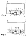
- Fig. 1, 2 and 3 show various embodiments of a device 1 for providing liquid reducing agent.
- a device 1 for providing liquid reducing agent In the the Fig. 1, 2 and 3 each illustrated different feature combinations of such a device are only exemplary. Features illustrated in various figures may be combined as desired with each other and with other features throughout the description.
- the device 1, comprising the tank 3, in which reducing agent can be stored, and the delivery unit 4, which is arranged in a chamber 9, can be seen.
- the chamber 9 is part of the tank bottom 25 or inserted into the tank bottom 25.
- the suction point 5 through which reducing agent can be sucked.
- the delivery unit 4 has a pump 17.
- the conveying unit 4 or the chamber 9 is surrounded by a separating layer 6.
- the separating layer 6 covers the suction point 5, a gap 7 being formed between the separating layer 6 and the suction point 5 or between the separating layer 6 and the conveying unit 4 or between the separating layer 6 and the chamber 9.
- a line connection 16 is available, to which a line can be connected, through which the reducing agent can be conveyed to an exhaust gas treatment device.
- a separation layer 6 which has a filter layer 14 for filtering the reducing agent and beyond a barrier layer 8, which influences the flow resistance of the separation layer 6 such that the flow resistance for reducing agent in the inflow direction 23 is less than the flow resistance in Outflow direction 24.
- the separation layer 6 according to the Fig. 1 a supporting structure 11, which holds the separating layer 6 in its position, or predetermines the shape of the separating layer 6.
- the support structure 11 is designed for example as a perforated plate.
- the separating layer 6 has a filter layer 14 and a heat protection layer 15, wherein the heat protection layer 15 is adapted to reduce the heat flow in the outflow direction 24, so that the gap 7 of the device 1 cools less rapidly and after a freezing phase in which the reducing agent in the tank 3 is frozen, in the space 7 if possible still liquid reducing agent is present.
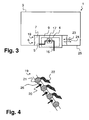
- a guide structure 10 is shown, which ensures that at an oblique position of the device 1 and the tank 3 or in sloshing movements in the tank 3 reducing agent reaches the separation layer 6.
- the separating layer 6 is formed with a sieve 19, which is designed such that the flow of reducing agent in the outflow direction 24 is difficult and the flow of reducing agent in the inflow direction 23 is simplified.
- the screen 19 is constructed, for example, of wires 21, between which there are openings 26, through which a reducing agent flow 20 can flow. Disposed on one side on the wires 21 of the screen 19 are flow obstruction means 22, which can lie in front of the openings 26 when the reducing agent flow 20 flows in the opposite direction.
- the flow obstruction means 22 act as a valve means.
- a screen 19 can also be combined with a filter layer 14. Such a sieve 19 can then at the same time a support function for take over the filter layer 14 and set the shape or the shape and position of the filter layer 14.
- the separating layer 6 is then formed by a sieve 19 with flow obstruction means 22 in combination with a filter layer 14.
- a device 1 is shown from above.
- the tank 3 can be seen.
- the chamber 9 In the tank 3 is the chamber 9, in which the conveyor unit 4 is arranged.
- the suction point 5 At the chamber 9 is the suction point 5, through which reducing agent can reach the conveyor unit 4. Reducing agent is sucked by the conveyor unit 4 by means of the pump 17.
- the separation layer 6 Around the chamber 9 or the delivery unit 4 around is the separation layer 6, so that around the chamber 9 around an annular gap 7 is formed, which covers the suction 5.
- various guide structures 10 are arranged, which guide the reducing agent at an oblique position of the tank 3 or the device 1 or in the case of sloshing movements in the tank 3 towards the separating layer 6.
- an inflow direction 23 and an outflow direction 24 are defined.
- the separating layer 6 is in the Fig. 5 by way of example with a filter layer 14 and with a barrier layer 8.
- Fig. 6 shows a motor vehicle 12 comprising an internal combustion engine 13 and an exhaust gas treatment device 2 for cleaning the exhaust gases of the internal combustion engine 13.
- the exhaust gas treatment device 2 is flowed from the exhaust gas with an exhaust gas flow direction 27 starting from the internal combustion engine 2.
- reducing agent with a device 1 for providing liquid reducing agent via an injector 28 can be fed.
- the device 1 has a tank 3, in which the reducing agent is stored, as well as a delivery unit 4, which supplies the reducing agent out of the tank 3 promotes the injector 28.
- the device 1 may be designed according to the description given above.
- an SCR catalyst 29 is arranged, in which the SCR method is performed. Nitrogen oxide compounds in the exhaust gas are reacted with the reducing agent.
- the motor vehicle 12 also has a control unit 30, which is set up to control the operation of the device 1.
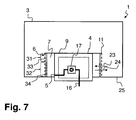
- Fig. 7 shows a further embodiment of a device 1, comprising a tank 3 and a conveyor unit 4, which is arranged in a chamber 9 on the tank bottom 25.
- the delivery unit 4 removes the reducing agent from the tank 3 at a suction point 5.
- the delivery unit 4 has a pump 17, with which the liquid additive is pumped.
- the delivery unit 4 provides the liquid additive to the conduit port 16.
- the suction point 5 is covered by a separating layer 6, so that a closed gap 7 is formed.
- the separating layer 6 is shaped like a cylinder and arranged (round) around the chamber 9. The surface of this cylinder forms the surface of the separating layer 6.
- the separating layer 6 has a supporting structure 11, which may be designed in the manner of a sieve.
- the surface of the separating layer 6 is divided into a first zone 31 and a second zone 32.
- the separating layer 6 is at least partially formed from a first material 33.
- the separating layer 6 is at least partially formed from a second material 34.
- the first material 33 has improved air permeability over the second material 34.
- the second material 34 preferably has an improved permeability for reducing agent in an inflow direction 23 than in an outflow direction 24.
Landscapes
- Chemical & Material Sciences (AREA)
- Engineering & Computer Science (AREA)
- Chemical Kinetics & Catalysis (AREA)
- Health & Medical Sciences (AREA)
- Toxicology (AREA)
- Combustion & Propulsion (AREA)
- Mechanical Engineering (AREA)
- General Engineering & Computer Science (AREA)
- Exhaust Gas After Treatment (AREA)
- Exhaust Gas Treatment By Means Of Catalyst (AREA)
- Treating Waste Gases (AREA)
Description
Die Erfindung betrifft eine Vorrichtung zur Bereitstellung von flüssigem Reduktionsmittel für eine Abgasbehandlungsvorrichtung. Insbesondere im Kraftfahrzeugbereich sind Abgasbehandlungsvorrichtungen weit verbreitet, in welche eine zusätzliche Substanz zugeführt wird, um das Abgas einer Verbrennungskraftmaschine zu reinigen. Ein besonders häufig in solchen Abgasbehandlungsvorrichtungen durchgeführtes Abgasreinigungsverfahren ist das Verfahren der selektiven katalytischen Reduktion [SCR-Verfahren, SCR = Selective Catalytic Reduction]. Bei diesem Verfahren wird dem Abgas ein Reduktionsmittel zugeführt, mit welchem Stickstoffoxidverbindungen im Abgas reduziert werden können. Als Reduktionsmittel wird regelmäßig Ammoniak eingesetzt. Ammoniak wird in Kraftfahrzeugen normalerweise nicht direkt bevorratet, sondern in Form einer Vorläuferlösung, welche zu Ammoniak umgesetzt werden kann. Die Umsetzung kann innerhalb der Abgasbehandlungsvorrichtung erfolgen und/oder in einem dafür vorgesehenen zusätzlichen Reaktor, welcher in der Abgasleitung und/oder abgasextern angeordnet sein kann. Als Reduktionsmittelvorläufer kann beispielsweise eine wässrige Harnstoff-Lösung verwendet werden. Eine 32,5-prozentige Harnstoff-Wasser-Lösung ist als Reduktionsmittelvorläufer unter dem Handelsnamen AdBlue® erhältlich. Die Begriffe "Reduktionsmittel" und "Reduktionsmittelvorläuferlösung" bzw. "Reduktionsmittelvorläufer" werden im Folgenden synonym füreinander verwendet.The invention relates to a device for providing liquid reducing agent for an exhaust gas treatment device. Especially in the automotive field exhaust treatment devices are widely used, in which an additional substance is supplied to clean the exhaust gas of an internal combustion engine. A particularly frequently run in such an exhaust gas treatment devices, exhaust gas purification method is the method of selective catalytic reduction [SCR process, SCR = Selective Catalytic Reduction]. In this method, a reducing agent is supplied to the exhaust gas, with which nitrogen oxide compounds in the exhaust gas can be reduced. As a reducing agent ammonia is used regularly. Ammonia is not normally stored directly in motor vehicles, but in the form of a precursor solution which can be converted to ammonia. The reaction can take place within the exhaust gas treatment device and / or in a dedicated additional reactor, which can be arranged in the exhaust pipe and / or exhaust gas outside. As the reducing agent precursor, for example, an aqueous urea solution can be used. A 32.5 percent urea aqueous solution is available as a reducing agent precursor under the trade name AdBlue ®. The terms "reducing agent" and "reducing agent precursor solution" or "reducing agent precursor" are used interchangeably below.
Zur Bereitstellung des Reduktionsmittels für eine Abgabehandlungsvorrichtung ist in einem Kraftfahrzeug normalerweise ein Tank für das Reduktionsmittel und eine Fördereinheit zur Förderung des Reduktionsmittels aus dem Tank zu der Abgasbehandlungsvorrichtung vorgesehen. Der Tank und die Fördereinheit sollten möglichst kostengünstig sein und gleichzeitig eine sichere Bereitstellung des Reduktionsmittels gewährleisten. Als problematisch hat sich insbesondere herausgestellt, dass das Reduktionsmittel in dem Tank Verunreinigungen aufweist, welche dazu geeignet sind, die Fördereinheit oder einen Injektor zur Eindüsung des Reduktionsmittels in die Abgasbehandlungsvorrichtung zu beschädigen. Daher weist eine Fördereinheit typischerweise einen Filter auf, durch welchen Verunreinigungen im Reduktionsmittel zurückgehalten werden können.To provide the reducing agent for a discharge treatment device, in a motor vehicle, there is normally provided a tank for the reducing agent and a delivery unit for delivering the reducing agent from the tank to the exhaust gas treatment device. The tank and the Feed unit should be as inexpensive as possible and at the same time ensure safe delivery of the reducing agent. In particular, it has proven to be problematic that the reducing agent in the tank has contaminants which are suitable for damaging the delivery unit or an injector for injecting the reducing agent into the exhaust gas treatment device. Therefore, a delivery unit typically has a filter through which impurities in the reducing agent can be retained.
Aus der
Hiervon ausgehend ist es Aufgabe der hier vorliegenden Erfindung, die im Zusammenhang mit dem Stand der Technik geschilderten technischen Probleme zu lösen bzw. zumindest zu lindem. Es soll insbesondere eine besonders kostengünstige Vorrichtung zur zuverlässigen Bereitstellung von flüssigem Reduktionsmittel für eine Abgasbehandlungsvorrichtung vorgestellt werden.On this basis, it is an object of the present invention to solve the technical problems described in connection with the prior art or at least to lindem. In particular, a particularly cost-effective device for the reliable provision of liquid reducing agent for an exhaust gas treatment device is to be presented.
Diese Aufgaben werden gelöst mit einer Vorrichtung gemäß den Merkmalen des Patentanspruchs 1. Weitere vorteilhafte Ausgestaltungen der Vorrichtung sind in den abhängig formulierten Patentansprüchen angegeben. Die in den Patentansprüchen einzeln aufgeführten Merkmale sind in beliebiger, technologisch sinnvoller Weise miteinander kombinierbar und können durch erläuternde Sachverhalte aus der Beschreibung ergänzt werden, wobei weitere Ausführungsvarianten der Erfindung aufgezeigt werden.These objects are achieved with a device according to the features of
Erfingdungsgemäß ist eine Vorrichtung zur Bereitstellung von flüssigem Reduktionsmittel für eine Abgasbehandlungsvorrichtung, aufweisend einen Tank und eine Fördereinheit mit einer Ansaugstelle im Tank, an der Reduktionsmittel aus dem Tank angesaugt werden kann, wobei die Ansaugstelle von einer Trennlage abgedeckt ist, so dass ein geschlossener Zwischenraum zwischen der Ansaugstelle und der Trennlage vorliegt, wobei die Trennlage in einer Ausströmrichtung von dem Zwischenraum in den Tank hinein einen höheren Strömungswiderstand für Reduktionsmittel aufweist als in einer Einströmrichtung von dem Tank in den Zwischenraum hinein.According to the invention, a device for providing liquid reducing agent for an exhaust gas treatment device, comprising a tank and a conveyor unit with a suction point in the tank, can be sucked at the reducing agent from the tank, wherein the suction point is covered by a separating layer, so that a closed space between the suction point and the separating layer is present, wherein the separating layer has a higher flow resistance for reducing agent in an outflow direction from the intermediate space into the tank than in an inflow direction from the tank into the intermediate space.
Die Ansaugstelle im Tank ist vorzugsweise eine Öffnung in der Wand des Tanks, an welche sich eine Leitung anschließt, welche zu der Fördereinheit führt. Ebenso ist möglich, dass die Ansaugstelle in entsprechender Weise an einem Gehäuse der Fördereinheit ausgebildet ist, welches in den Tank hineinragt. Die Trennlage bildet vorzugsweise eine Art Abdeckung über die Ansaugstelle. Die Trennlage kann beispielsweise nach Art einer Haube ausgeführt sein, welche über die Ansaugstelle gesetzt ist. Es ist auch möglich, dass die Ansaugstelle sich in einer Einbuchtung des Tanks bzw. in einer Einbuchtung der Tankwand befindet und die Trennlage diese Einbuchtung verschließt bzw. verdeckt. Mit anderen Worten überspannt die Trennlage bevorzugt die Ansaugstelle.The suction point in the tank is preferably an opening in the wall of the tank, which is followed by a line leading to the conveyor unit. It is also possible that the suction point is formed in a corresponding manner on a housing of the conveyor unit, which projects into the tank. The separating layer preferably forms a kind of cover over the suction point. The separating layer can be designed, for example, in the manner of a hood, which is set over the suction point. It is also possible that the suction point is located in an indentation of the tank or in a recess of the tank wall and the separating layer closes or conceals this indentation. In other words, the separating layer preferably spans the suction point.
Der Zwischenraum befindet sich vorzugsweise zwischen der Trennlage und einer Tankwand im Bereich der Ansaugstelle. Der Strömungswiderstand für Reduktionsmittel in Einströmrichtung oder in Ausströmrichtung ist durch die Menge an Reduktionsmittel definiert, welche bei einer vorgegebenen Druckdifferenz durch die Trennlage fließen kann. Der Strömungswiderstand muss bei unterschiedlichen Druckdifferenzen zwischen dem Zwischenraum und dem Tank nicht konstant sein. Es ist auch möglich, dass der Strömungswiderstand sich in Abhängigkeit der Druckdifferenz verändert. Im Rahmen der Erfindung ist bevorzugt, dass der Strömungswiderstand in Ausströmrichtung insbesondere im Bereich niedriger Drücke (Drücke bis 0,2 bar und insbesondere Drücke bis 0,1 bar) gegenüber dem Strömungswiderstand in Einströmrichtung wesentlich erhöht ist. 0,2 bar entsprechen einer Wassersäule von 2 m [Meter], 0,1 bar entsprechen einer Wässersäule von 1 m [Meter]. Höhere Drücke treten zwischen dem Tank und dem Zwischenraum normalerweise nicht auf. Die Druckdifferenz zwischen dem Zwischenraum und dem Tank wird im Wesentlichen durch den Massenstrom an Reduktionsmittel durch die Trennlage und durch die Flüssigkeitspegel im Zwischenraum und im Tank, sowie durch den Aufprall der Flüssigkeit bei Schwappbewegungen im Tank und im Zwischenraum bestimmt. Bei diesen Effekten ist vor allem der Anteil der Druckdifferenz durch den auftretenden Massenstrom an Reduktionsmittel vernachlässigbar. Dementsprechend sind die auftretenden Druckdifferenzen im Wesentlichen durch die Baugröße des Tanks bestimmt und überschreiten sehr selten die weiter oben genannten 0,2 bar. Daher ist es für die Funktion der Trennlage weniger relevant, wie diese sich bei höheren Druckdifferenzen verhält. Es ist beispielsweise möglich, dass die Strömungswiderstände der Trennlage in Einströmrichtung und in Ausströmrichtung bei Druckdifferenzen von mehr als 0,2 wieder ähnlicher werden oder sich vollständig angleichen.The intermediate space is preferably located between the separating layer and a tank wall in the region of the suction point. The flow resistance for reducing agent in the inflow direction or in the outflow direction is defined by the amount of reducing agent which can flow through the separating layer at a predetermined pressure difference. The flow resistance need not be constant at different pressure differences between the gap and the tank. It is also possible that the flow resistance changes depending on the pressure difference. In the context of the invention, it is preferred that the flow resistance in the outflow direction is substantially increased, in particular in the region of low pressures (pressures of up to 0.2 bar and in particular pressures of up to 0.1 bar) relative to the flow resistance in the inflow direction. 0.2 bar correspond to a water column of 2 m [meter], 0.1 bar correspond to a water column of 1 m [meters]. Higher pressures do not normally occur between the tank and the gap. The pressure difference between the intermediate space and the tank is essentially determined by the mass flow of reducing agent through the separating layer and by the liquid levels in the intermediate space and in the tank, as well as by the impact of the liquid during sloshing movements in the tank and in the intermediate space. Above all, the proportion of the pressure difference due to the mass flow of reducing agent that occurs is negligible in these effects. Accordingly, the pressure differences occurring are essentially determined by the size of the tank and exceed very rarely the above-mentioned 0.2 bar. Therefore, it is less relevant to the function of the separation layer, as it behaves at higher pressure differences. For example, it is possible that the flow resistances of the separating layer in the inflow direction and in the outflow direction become more similar or even completely equal at pressure differences of more than 0.2.
Durch eine solche unterschiedliche Ausgestaltung der Strömungswiderstände in Einströmrichtung und Ausströmrichtung kann im regulären Betrieb sichergestellt werden, dass Reduktionsmittel, welches durch die Trennlage in den Zwischenraum gelangt ist, nicht oder nur in einem begrenzten Maße wieder zurück in den Tank fließt.By such a different embodiment of the flow resistances in the inflow and outflow can be ensured in regular operation that reducing agent, which has passed through the separation layer into the gap, not or only to a limited extent flows back into the tank.
Mit einer Trennlage wird insbesondere eine räumliche Abtrennung des Zwischenraums vom restlichen Tankvolumen erreicht, der z. B. als Zwischenspeicher oder Reservoir für die Fördereinheit dient. Das dort befindliche Reduktionsmittel kann eine andere Eigenschaft (z. B. eine andere Sauberkeit oder eine andere Reinheit) aufweisen als das Reduktionsmittel im restlichen Tank.With a separation layer in particular a spatial separation of the gap is achieved by the remaining tank volume, the z. B. serves as a buffer or reservoir for the conveyor unit. The reducing agent located there may have a different property (eg, different cleanliness or purity) than the reducing agent in the remainder of the tank.
Die Trennlage kann auch mit einer Heizung ausgestattet sein, mit welcher das Reduktionsmittel in der Umgebung, insbesondere in dem Zwischenraum, aufgeheizt werden kann. Die Heizung kann beispielsweise wenigstens ein Heizelement (insbesondere PTC-Heizelemente) umfassen, welches in der Trennlage eingearbeitet ist. Beispielsweise können Heizdrähte in die Trennlage eingewoben sein. Diese Heizung kann auch dazu eingerichtet sein, das Reduktionsmittel in dem Tank aufzuheizen, jedoch sollte die Heizung überwiegend das Reduktionsmittel in dem Zwischenraum aufheizen. Bevorzugt wird die von der Heizung abgegebene Wärme zunächst überwiegend in den Zwischenraum abgegeben. Wenn das Reduktionsmittel in dem Zwischenraum flüssig ist, gelangt die Wärme der Heizung auch in den Tank. Die Heizung ist dazu vorzugsweise auf einer zu dem Zwischenraum gewandten inneren Seite der Trennlage vorgesehen.The separating layer can also be equipped with a heater, with which the reducing agent in the environment, especially in the Space, can be heated up. The heater may comprise, for example, at least one heating element (in particular PTC heating elements), which is incorporated in the separating layer. For example, heating wires can be woven into the separating layer. This heater may also be configured to heat the reductant in the tank, however, the heater should primarily heat the reductant in the gap. Preferably, the heat given off by the heater is initially emitted predominantly into the intermediate space. If the reducing agent in the space is liquid, the heat of the heater also enters the tank. For this purpose, the heater is preferably provided on an inner side of the separating layer facing the intermediate space.
Die Trennlage kann bevorzugt mehrere oder verschiedene Funktionen bei der Bereitstellung von Reduktionsmittel erfüllen, wie Filtern, Sieben, Heizen usw.The separation layer may preferably perform several or different functions in the provision of reducing agent, such as filtering, screening, heating, etc.
Die Trennlage kann auch einen Füllstandsensor zur Messung des Füllstandes in dem Tank aufweisen. Der Füllstandsensor kann beispielsweise nach Art von elektrischen Kontakten ausgebildet sein, welche an der Trennlage befestigt sind. Ebenso ist möglich, dass durch Prüfung des elektrischen Widerstandes einer Komponente (insbesondere eines Heizelements) der Trennlage auf die Temperatur geschlossen wird.The separation layer can also have a fill level sensor for measuring the fill level in the tank. The fill level sensor can be designed, for example, in the manner of electrical contacts which are fastened to the separating layer. It is also possible that by checking the electrical resistance of a component (in particular a heating element) of the separating layer is closed to the temperature.
Die beschriebene Vorrichtung ist weiter vorteilhaft, wenn die Trennlage für Reduktionsmittel in Einströmrichtung zumindest bis zu einer Schwelldruckdifferenz zwischen dem Tank und dem Zwischenraum von 0,01 bar bis 0,1 bar nur unidirektional durchlässig ist.The described device is also advantageous if the separating layer for reducing agent in the inflow direction is only unidirectionally permeable at least up to a threshold pressure difference between the tank and the intermediate space of 0.01 bar to 0.1 bar.
Durch eine derartige Ausgestaltung der Trennlage kann zumindest im Bereich der Druckdifferenzen zwischen Tank und Zwischenraum, welche im regulären Betrieb auftreten, vollständig verhindert werden, dass Reduktionsmittel vom Zwischenraum zurück in den Tank strömt. Die Wirkung der Trennlage ist damit besonders effektiv.Such a configuration of the separating layer can be completely prevented, at least in the region of the pressure differences between the tank and the intermediate space, which occur during normal operation Reducing agent flows from the gap back into the tank. The effect of the separation layer is thus particularly effective.
Eine solche Trennlage kann eine semipermeable Struktur sein, also mit anderen Worten insbesondere eine Struktur, die halb durchlässig, d. h. sie lässt nur bestimmte Stoffe (Reduktionsmittelanteile) durch und/oder Stoffe nur in einer (einzigen) Richtung durch. Diese Membran kann z. B. mehrere Lagen eines Textilgewebes umfassen, wobei insbesondere eine Teflon-Lage (Polytetrafluorethylen) vorgesehen ist.Such a separation layer may be a semi-permeable structure, in other words, in particular, a structure that is semi-permeable, ie. H. it passes through only certain substances (reducing agent components) and / or substances only in one (single) direction. This membrane can, for. B. comprise several layers of a textile fabric, in particular a Teflon layer (polytetrafluoroethylene) is provided.
Eine solche Trennlage kann aus einer Kombination einer Filterschicht/Siebschicht mit einem Schwamm auf der gefilterten Seite (im vorliegenden Fall auf der Innenseite) bestehen. Der Schwamm kann als dünne Schwammschicht ausgebildet sein, welche auf der Filterschicht/Siebschicht anliegt bzw. mit der Filterschicht/Siebschicht fest verbunden ist. Die Schwammschicht ist vorzugsweise dünner als 2 mm [Millimeter], und besonders bevorzugt dünner als 1 mm. In dem Schwamm bzw. der Schwammschicht wirken Kapillarkräfte. Durch diese Kapillarkräfte hält die Trennlage ein Volumen an Reduktionsmittel zurück. So wird eine Sperrschicht ausgebildet, welche einen Rückfluss des Reduktionsmittels durch die Filterschicht/Siebschicht verhindert.Such a separating layer can consist of a combination of a filter layer / sieve layer with a sponge on the filtered side (in this case on the inside). The sponge may be formed as a thin sponge layer which rests on the filter layer / screen layer or is firmly connected to the filter layer / screen layer. The sponge layer is preferably thinner than 2 mm [millimeter], and more preferably thinner than 1 mm. Capillary forces act in the sponge or sponge layer. Due to these capillary forces, the separating layer retains a volume of reducing agent. Thus, a barrier layer is formed which prevents backflow of the reducing agent through the filter layer / screen layer.
Die Vorrichtung ist auch vorteilhaft, wenn die Trennlage ein Filter ist, der zumindest eine Sperrschicht aufweist, welche den Strömungswiderstand der Trennlage in Ausströmrichtung erhöht.The device is also advantageous if the separating layer is a filter which has at least one barrier layer which increases the flow resistance of the separating layer in the outflow direction.
Die Sperrschicht hat in Ausströmrichtung zumindest im Bereich niedriger Druckdifferenzen zwischen dem Zwischenraum und dem Tank eine Sperrwirkung. Hiermit ist gemeint, dass die Sperrschicht eine Strömung von Reduktionsmittel aus dem Tank heraus verhindert.The barrier layer has a blocking effect in the outflow direction, at least in the region of low pressure differences between the intermediate space and the tank. By this is meant that the barrier prevents a flow of reductant from the tank.
Auch eine derartige Sperrschicht kann mit einer geeigneten sempermeablen Struktur gebildet sein. Eine Sperrschicht kann ggf. auch mehrlagig ausgeführt sein, um eine verbesserte Sperrwirkung zu gewährleisten.Such a barrier layer can also be formed with a suitable sempermeablen structure. If necessary, a barrier layer can also be multi-layered in order to ensure an improved blocking effect.
Somit kann die Trennlage eine Filterwirkung haben. In den Zwischenraum einströmendes Reduktionsmittel wird gefiltert. So können Verunreinigungen des Reduktionsmittels im Tank von der Ansaugstelle ferngehalten werden. Es wird verhindert, dass Verunreinigungen in den Zwischenraum bzw. zu der Ansaugstelle gelangen. Gleichzeitig wird durch den erhöhten Strömungswiderstand in Ausströmrichtung gewährleistet, dass bereits gefiltertes Reduktionsmittel nicht aus dem Zwischenraum zurück in den Tank gelangt. So kann verhindert werden, dass Reduktionsmittel doppelt gefiltert wird. Gleichzeitig befindet sich in dem Zwischenraum in unmittelbarer Umgebung der Ansaugstelle jeweils ein Reservoir an gefiltertem Reduktionsmittel.Thus, the release liner can have a filtering effect. In the space flowing in reducing agent is filtered. So contaminants of the reducing agent in the tank can be kept away from the intake. It prevents impurities from getting into the gap or to the suction point. At the same time it is ensured by the increased flow resistance in the outflow that already filtered reducing agent does not get from the gap back into the tank. Thus it can be prevented that reducing agent is filtered twice. At the same time, a reservoir of filtered reducing agent is located in the intermediate space in the immediate vicinity of the suction point.
Die Sperrwirkung und die Filterwirkung können in zwei unterschiedlichen Schichten der Trennlage realisiert sein. Dann ist neben der Sperrschicht vorzugsweise auch noch eine Filterschicht vorgesehen, welche die Filterwirkung übernimmt. Die Trennlage ist dann mehrlagig. Die Sperrschicht und die Filterschicht können auch in einer gemeinsamen Schicht realisiert sein, welche die beschriebene Sperrwirkung und die beschriebene Filterwirkung miteinander kombiniert. Die kombinierte Filterschicht und Sperrschicht kann beispielsweise Poren und/oder Kanäle aufweisen, die (unter normalen Betriebsbedingungen) in Einströmrichtung für Reduktionsmittel durchlässig sind und Partikel die größer sind als die Poren bzw. Kanäle zurückhalten, und die in Ausströmrichtung weder für Reduktionsmittel noch für derartige Partikel durchlässig sind.The blocking effect and the filtering action can be realized in two different layers of the separating layer. Then, in addition to the barrier layer preferably also a filter layer is provided which takes over the filter effect. The separation layer is then multi-layered. The barrier layer and the filter layer can also be realized in a common layer which combines the described blocking effect and the described filter effect. The combined filter layer and barrier layer may, for example, have pores and / or channels which are permeable to reducing agent in the inflow direction (under normal operating conditions) and particles which are larger than the pores or channels, and in the outflow direction neither for reducing agents nor for such particles are permeable.
Die Vorrichtung ist auch vorteilhaft, wenn die Trennlage ein Sieb ist, welches zumindest ein Strömungsbehinderungsmittel aufweist, welches den Strömungswiderstand der Trennlage in Ausströmrichtung erhöht.The device is also advantageous if the separating layer is a sieve which has at least one flow obstruction means which increases the flow resistance of the separating layer in the outflow direction.
Durch ein Sieb ist es ebenfalls möglich, Reduktionsmittel auf dem Weg aus dem Tank in den Zwischenraum zu reinigen. Ein Sieb hat Öffnungen mit einer einheitlichen Größe. Die Öffnungen können beispielsweise einen einheitlichen Durchmesser von weniger als 1 mm [Millimeter], vorzugsweise weniger als 0,5 mm [Millimeter] und besonders bevorzugt zwischen 10 µm [Mikrometer] und 20 µm haben. Durch ein Sieb können Partikel im Reduktionsmittel zurückgehalten werden, so dass diese nicht in den Zwischenraum und damit auch nicht zu der Ansaugstelle gelangen. Zur Erhöhung des Strömungswiderstands aus dem Zwischenraum zurück in den Tank kann bei der Ausführung der Trennlage als Sieb zumindest ein Strömungsbehinderungsmittel vorgesehen sein. Strömungsbehinderungsmittel können beispielsweise Ventilmittel sein, welche die Öffnungen des Siebs im Falle eines sich anbahnenden Rückstroms aus dem Zwischenraum in den Tank (in Ausströmrichtung) verschließen. Strömungsbehinderungsmittel bzw. Ventilmittel können beispielsweise bewegliche Fahnen sein, welche einseitig an dem Sieb befestigt sind und sich im Falle einer Strömung ausgehend von der Seite des Siebes mit den Fahnen vor die Öffnungen des Siebes legen. Im Falle der als Sieb ausgeführten Trennlage bei der beschriebenen Vorrichtung sind die Fahnen vorzugsweise auf der zwischenraumseitigen Seite des Siebes befestigt. Einen Rückstrom aus dem Zwischenraum zurück in den Tank (in Ausströmrichtung) können die Fahnen effektiv verhindern.Through a sieve, it is also possible to clean reducing agent on the way out of the tank into the space. A sieve has openings with a uniform size. For example, the openings may have a uniform diameter of less than 1 mm [millimeter], preferably less than 0.5 mm [millimeter], and more preferably between 10 μm [micrometer] and 20 μm. Through a sieve particles can be retained in the reducing agent, so that they do not get into the space and thus not to the intake. In order to increase the flow resistance from the intermediate space back into the tank, at least one flow obstruction means can be provided as a sieve in the embodiment of the separating layer. Flow obstruction means may be, for example, valve means which close the openings of the sieve in the event of an approaching return flow from the intermediate space into the tank (in the outflow direction). Flow obstruction means or valve means may be, for example, movable vanes, which are attached to one side of the screen and in the case of a flow, starting from the side of the screen with the flags in front of the openings of the screen. In the case of the separating layer designed as a sieve in the described device, the lugs are preferably fastened on the space side of the screen. A backflow from the gap back into the tank (in the outflow direction) can effectively prevent the flags.
Weiterhin ist die Vorrichtung vorteilhaft, wenn die Fördereinheit in einer Kammer angeordnet ist, welche zumindest teilweise in dem Tank angeordnet ist, und die Trennlage die Kammer derart umgibt, dass ein umlaufender Zwischenraum zwischen der Kammer und der Trennlage vorliegt.Furthermore, the device is advantageous if the delivery unit is arranged in a chamber which is at least partially disposed in the tank, and the separation layer surrounds the chamber such that there is a circumferential gap between the chamber and the separation layer.
Die Trennlage umgibt die Kammer vorzugsweise radial umlaufend, so dass z. B. ein umlaufender, insbesondere ein ringförmiger Zwischenraum zwischen der Kammer und der Trennlage vorliegt. Die Kammer ist vorzugsweise Bestandteil des Tankbodens. Die Kammer erstreckt sich vorzugsweise ausgehend von dem Tankboden nach oben in das Tankvolumen hinein. Die Kammer erstreckt sich aber vorzugsweise maximal über 30 % und besonders bevorzugt maximal über 15 % der Tankhöhe. Bei dieser Bauart kann die Ansaugstelle sich an der Kammer und damit in unmittelbarer Nähe der Fördereinheit befinden und gleichzeitig in der Nähe des Tankbodens angeordnet sein, so dass das Reduktionsmittel aus dem Tank möglichst vollständig über die Ansaugstelle angesaugt werden kann.The separation layer surrounds the chamber preferably radially encircling, so that z. B. a circumferential, in particular an annular space between the chamber and the separating layer is present. The chamber is preferably part of the tank bottom. The chamber preferably extends upwards from the tank bottom into the tank volume. However, the chamber preferably extends at most over 30% and more preferably at most over 15% of the tank height. In this design, the suction point can be located at the chamber and thus in the immediate vicinity of the conveyor unit and at the same time be arranged in the vicinity of the tank bottom, so that the reducing agent from the tank can be sucked as completely as possible via the suction point.
Zwischen der Kammer und der Trennlage kann auch eine Abstandstruktur vorgesehen sein, um einen Abstand zwischen der Kammer und der Trennlage sicher zu stellen. So kann ein ausreichend großes Reservoir für gefiltertes Reduktionsmittel zwischen der Kammer und der Trennlage bereitgestellt werden. Aufgrund der Eigenschaften der Trennlage fließt das Reduktionsmittel aus diesem Reservoir nicht oder nur zeitlich verzögert zurück in den Tank. So kann erreicht werden, dass bei Kurvenfahrten und bei Schwappbewegungen im Tank jeweils Reduktionsmittel an der Ansaugstelle zur Verfügung steht.A spacing structure may also be provided between the chamber and the separating layer in order to ensure a distance between the chamber and the separating layer. Thus, a sufficiently large reservoir of filtered reductant may be provided between the chamber and the separator. Due to the properties of the separating layer, the reducing agent from this reservoir does not flow back into the tank, or only with a time lag. Thus, it can be achieved that when cornering and sloshing movements in the tank each reducing agent is available at the intake.
Auch vorteilhaft ist die Vorrichtung, wenn in dem Tank um die Trennlage herum zumindest eine Leitstruktur angeordnet ist, welche das Reduktionsmittel hin zu der Trennlage leitet.The device is also advantageous if at least one guide structure is arranged in the tank around the separating layer and directs the reducing agent towards the separating layer.
Die Leitstruktur kann beispielsweise in Form von Leitblechen ausgebildet sein, welche das Reduktionsmittel insbesondere bei einer Schräglage des Tanks oder bei Schwappbewegungen im Tank hin zu der Trennlage leiten. So kann erreicht werden, dass sich das Reduktionsmittel im Tank außen vor der Trennlage sammelt und in den Zwischenraum geführt wird. Aus dem Zwischenraum fließt das Reduktionsmittel aufgrund des erhöhten Strömungswiderstands in Ausströmrichtung nicht oder nur wesentlich langsamer wieder hinaus. So verbleibt auch bei einer Schräglage des Tanks oder bei Schwappbewegungen im Tank jeweils in dem Zwischenraum in unmittelbarer Umgebung der Ansaugstelle eine Menge an Reduktionsmittel, so dass die Förderung von Reduktionsmittel mit der Fördereinheit nicht unterbrochen wird. Dies gilt selbst dann, wenn der Reduktionsmittelfüllstand in dem Tank bereits stark reduziert ist.The guide structure may be formed, for example, in the form of baffles which guide the reducing agent in particular in the case of an inclined position of the tank or in the event of sloshing movements in the tank towards the separating layer. So it can be achieved that the reducing agent in the tank outside collects in front of the separating layer and is guided into the intermediate space. Due to the increased flow resistance in the outflow direction, the reducing agent does not flow out of the intermediate space or only at a much slower rate. Thus, even in the case of an inclined position of the tank or in the event of sloshing movements in the tank, an amount of reducing agent remains in the intermediate space in the immediate vicinity of the suction point, so that the delivery of reducing agent to the delivery unit is not interrupted. This is true even if the reducing agent level in the tank is already greatly reduced.
Die Vorrichtung ist darüber hinaus vorteilhaft, wenn die Trennlage für Luftblasen in Ausströmrichtung aus dem Zwischenraum hinaus durchlässig ist. So kann verhindert werden, dass sich Luftblasen in dem Zwischenraum sammeln. Geeignete semipermeable Materialien, die für Reduktionsmittel nur in eine Richtung durchlässig sind und daher als Sperrschicht wirken, können für Luft bidirektional, also in beide Richtungen, durchlässig sein. Mit Membranen aus derartigen Materialien kann eine Durchlässigkeit der Trennlage für Luftblasen realisiert sein.The device is furthermore advantageous if the separating layer for air bubbles in the outflow direction is permeable to the gap. This can prevent air bubbles from accumulating in the gap. Suitable semipermeable materials, which are permeable to reducing agent in one direction only and therefore act as a barrier layer, can be bi-directional, ie in both directions, permeable to air. With membranes of such materials, a permeability of the separator for air bubbles can be realized.
Weiterhin vorteilhaft ist die Vorrichtung, wenn die Trennlage einen Wärmefluss in Einströmrichtung begünstigt und den Wärmefluss in Ausströmrichtung reduziert.Furthermore, the device is advantageous if the separating layer favors a heat flow in the inflow direction and reduces the heat flow in the outflow direction.
So kann verhindert werden, dass das Reduktionsmittel in dem Zwischenraum im Einfrierfall schneller einfriert als in dem Tank. Vorzugsweise verbleibt in dem Zwischenraum flüssiges Reduktionsmittel, wenn das Reduktionsmittel im Tank bereits eingefroren ist. So ist es möglich, dass beim Start der Fördereinheit gegebenenfalls direkt flüssiges Reduktionsmittel an der Ansaugstelle vorliegt, obwohl das Reduktionsmittel in dem Tank größtenteils eingefroren ist. Daher ist es dann nicht notwendig den Zwischenraum zunächst mit einer Heizung freizuschmelzen.Thus, it can be prevented that the reducing agent freezes faster in the gap in freezing than in the tank. Preferably, liquid reducing agent remains in the space when the reducing agent in the tank is already frozen. Thus, it is possible that at the start of the conveyor unit, if appropriate, directly liquid reducing agent is present at the suction point, although the reducing agent is largely frozen in the tank. Therefore, it is then not necessary to first freeze the gap with a heater.
Auch vorteilhaft ist die Vorrichtung, wenn die Trennlage eine Stützstruktur aufweist, die der Trennlage Stabilität gibt, wobei der Strömungswiderstand der Stützstruktur für Reduktionsmittel in Einströmrichtung und in Ausströmrichtung vernachlässigbar ist.The device is also advantageous if the separating layer has a supporting structure which gives stability to the separating layer, wherein the flow resistance of the reducing agent supporting structure in the inflow and outflow directions is negligible.
Der Strömungswiderstand ist insbesondere im Vergleich zu dem Strömungswiderstand von weiteren Schichten der Trennlage vernachlässigbar. Die Stützstruktur erfüllt somit praktisch keine relevante Filterwirkung, sondern sie dient lediglich dazu, die Form und Position der Trennlage vorzugeben. Die Stützstruktur kann beispielsweise als Blechkonstruktion ausgeführt sein, welche die weiteren Schichten der Trennlage umschließt bzw. an welcher die weiteren Schichten der Trennlage anliegen. Die Stützstruktur kann beispielsweise zumindest einen Rahmen für die Trennlage bilden. Die Stützstruktur kann als Fachwerkkonstruktion ausgebildet sein, welche ein Balkengerüst aufspannt, an dem die weiteren Schichten der Trennlage anliegen können. Eine Stützstruktur ist insbesondere vorteilhaft, wenn die Trennlage einen Filter umfasst, weil ein Filter normalerweise eine relativ geringe mechanische Stabilität aufweist und der Filter durch eine Stützstruktur daher besonders vorteilhaft in Position bzw. in der vorgesehenen Form gehalten werden kann. Die Stützstruktur und weitere Schichten (beispielsweise eine Filterschicht, eine Wärmeschutzschicht und/oder eine Sperrschicht) der Trennlage können auch miteinander verbunden sein. Es ist beispielsweise möglich, dass die Stützstruktur weitere Schichten der Trennlage teilweise durchdringt und/oder teilweise in weitere Schichten der Trennlage eindringt und die Stützstruktur weitere Schichten der Trennlage so mechanisch hält. Weitere Schichten der Trennlage können an der Stützstruktur auch angeschweißt oder angeklebt sein. Die Verbindung zwischen der Trennlage und der Stützstruktur kann in linienartigen Bereichen (beispielsweise an den Rändern der Trennlage) und/oder flächig ausgebildet sein.The flow resistance is negligible especially in comparison to the flow resistance of further layers of the separation layer. The support structure thus fulfills practically no relevant filter effect, but it merely serves to predetermine the shape and position of the separating layer. The support structure can be designed, for example, as a sheet metal construction, which encloses the further layers of the separating layer or against which the further layers of the separating layer rest. The support structure may, for example, form at least one frame for the separating layer. The support structure may be formed as a truss structure, which spans a beam framework, on which the further layers of the separation layer can rest. A support structure is particularly advantageous if the separation layer comprises a filter, because a filter normally has a relatively low mechanical stability and the filter can therefore be held by a support structure particularly advantageous in position or in the intended form. The support structure and further layers (for example a filter layer, a heat protection layer and / or a barrier layer) of the separation layer can also be connected to one another. It is possible, for example, for the supporting structure to partially penetrate further layers of the separating layer and / or to partially penetrate into further layers of the separating layer and for the supporting structure to mechanically hold further layers of the separating layer. Other layers of the release liner may also be welded or adhered to the support structure. The connection between the separating layer and the supporting structure may be formed in line-like regions (for example at the edges of the separating layer) and / or in a planar manner.
In einer weiteren vorteilhaften Ausführungsvariante der Vorrichtung sind die Eigenschaften der Trennlage über die Fläche der Trennlage unterschiedlich. Hiermit ist insbesondere gemeint, dass die Trennlage zumindest abschnittsweise verschiedene Eigenschaften aufweist. Bevorzugt kann die Fläche der Trennlage in zumindest zwei Zonen unterteilt werden, wobei die Eigenschaften der Trennlage in den Zonen unterschiedlich sind. Es ist auch möglich, dass sich die Eigenschaften der Trennlage über die Fläche der Trennlage betrachtet kontinuierlich ändern.In a further advantageous embodiment variant of the device, the properties of the separating layer are different over the surface of the separating layer. This means, in particular, that the separating layer has different properties at least in sections. Preferably, the area of the separating layer can be subdivided into at least two zones, the properties of the separating layer being different in the zones. It is also possible that the properties of the release liner over the area of the release liner changes continuously.
Mit den Eigenschaften der Trennlage sind hier sämtliche weiter oben bereits beschriebenen Eigenschaften gemeint, wie beispielsweise die unidirektionale Durchlässigkeit oder die bidirektionale Durchlässigkeit der Trennlage für Reduktionsmittel und/oder für Luft, oder der Strömungswiderstand der Trennlage für Reduktionsmittel und/oder für Luft in Einströmrichtung und in Ausströmrichtung.By the properties of the separating layer are meant all the properties already described above, such as the unidirectional permeability or the bidirectional permeability of the separating layer for reducing agent and / or air, or the flow resistance of the separating layer for reducing agent and / or air in the inflow direction and in outflow.
Besonders bevorzugt ist, wenn die Trennlage eine erste Zone und eine zweite Zone aufweist, wobei sich (bei vorgesehener Einbauausrichtung der Vorrichtung) die erste Zone oberhalb der zweiten Zone befindet, wobei die Trennlage in der zweiten Zone in einer Ausströmrichtung von dem Zwischenraum in den Tank hinein einen höheren Strömungswiderstand für Reduktionsmittel aufweist als in einer Einströmrichtung von dem Tank in den Zwischenraum hinein, und wobei die Trennlage in der ersten Zone eine gegenüber der zweiten Zone verbesserte Durchlässigkeit aufweist. Vorzugsweise ist in der ersten Zone insbesondere eine verbesserte Durchlässigkeit für Luft in Ausströmrichtung gegeben.It is particularly preferred if the separating layer has a first zone and a second zone, with the first zone being located above the second zone (with the installation orientation of the device being provided), the separating layer in the second zone being in an outflow direction from the intermediate space into the tank in that it has a higher flow resistance for reducing agent than in an inflow direction from the tank into the intermediate space, and in which the separating layer in the first zone has an improved permeability compared to the second zone. In particular, in the first zone there is an improved permeability for air in the outflow direction.
Darüber hinaus ist es bevorzugt, wenn die Trennlage in der ersten Zone zumindest teilweise aus einem ersten Material aufgebaut ist und in der zweiten Zone zumindest teilweise aus einem zweiten Material aufgebaut ist, wobei das erste Material und das zweite Material insbesondere in Bezug auf die Durchlässigkeit für Luft und/oder für Reduktionsmittel unterschiedliche Eigenschaften aufweisen. Vorzugsweise ist das zweite Material für die Trennlage nicht in der ersten Zone verwendet und das erste Material für die Trennlage nicht in der zweiten Zone verwendet. Das erste Material hat vorzugsweise gegenüber dem zweiten Material eine verbesserte Durchlässigkeit für Luft. Das zweite Material hat vorzugsweise in beide Durchströmungsrichtungen (in einer Einströmrichtung und in einer Ausströmrichtung) einen unterschiedlichen Strömungswiderstand für Reduktionsmittel. Durch die zweite Zone der Trennlage wird vorzugsweise ein Raum gebildet, in dem sich Reduktionsmittel im Betrieb der Vorrichtung sammelt. Luftblasen in dem Zwischenraum zwischen der Ansaugstelle und der Trennlage können so durch die erste Zone aus dem Zwischenraum entweichen.Moreover, it is preferred if the separating layer is at least partially constructed of a first material in the first zone and at least partially constructed of a second material in the second zone is, wherein the first material and the second material, in particular with respect to the permeability to air and / or reducing agent have different properties. Preferably, the second material for the release liner is not used in the first zone and the first release liner material is not used in the second zone. The first material preferably has improved air permeability over the second material. The second material preferably has a different flow resistance for reducing agent in both through-flow directions (in an inflow direction and in an outflow direction). The second zone of the separating layer preferably forms a space in which reducing agent collects during operation of the device. Air bubbles in the space between the suction point and the separating layer can thus escape through the first zone from the intermediate space.
Im Rahmen der Erfindung auch beansprucht wird ein Kraftfahrzeug aufweisend eine Verbrennungskraftmaschine und eine Abgasbehandlungsvorrichtung zur Reinigung der Abgase der Verbrennungskraftmaschine, sowie eine Vorrichtung, welche dazu eingerichtet ist, die Abgasbehandlungsvorrichtung mit Reduktionsmittel zu versorgen. Die Abgasbehandlungsvorrichtung wird von dem Abgas der Verbrennungskraftmaschine mit einer Abgasströmungsrichtung durchströmt. Die Vorrichtung führt das Reduktionsmittel der Abgasbehandlungsvorrichtung über einen Injektor zu. Der Injektor ist zur Eindüsung und/oder zur Einspritzung des Reduktionsmittels in die Abgasbehandlungsvorrichtung eingerichtet. Der Injektor kann entweder eine selbstöffnende Düse sein oder durch ein ansteuerbares Ventilelement die Menge an Reduktionsmittel steuern, die der Abgasbehandlungsvorrichtung zugeführt wird. In der Abgasbehandlungsvorrichtung ist ein SCR-Katalysator angeordnet, in dem das SCR-Verfahren zur Abgasreinigung durchgeführt wird. Dabei werden Stickstoffoxidverbindungen in dem Abgas mit dem Reduktionsmittel zu unschädlichen Stoffen, wie Wasser, Kohlendioxid und Stickstoff umgesetzt.Also claimed within the scope of the invention is a motor vehicle comprising an internal combustion engine and an exhaust gas treatment device for cleaning the exhaust gases of the internal combustion engine, and a device which is adapted to supply the exhaust gas treatment device with reducing agent. The exhaust gas treatment device is flowed through by the exhaust gas of the internal combustion engine with an exhaust gas flow direction. The device supplies the reducing agent to the exhaust treatment device via an injector. The injector is set up for injection and / or injection of the reducing agent into the exhaust gas treatment device. The injector may either be a self-opening nozzle or control the amount of reducing agent supplied to the exhaust treatment device by a controllable valve element. In the exhaust treatment device, an SCR catalyst is arranged in which the SCR process for exhaust gas purification is performed. In this case, nitrogen oxide compounds in the exhaust gas with the reducing agent to harmless substances, such as water, carbon dioxide and nitrogen.
Es kann weiter vorteilhaft sein, dass in und/oder an der Trennlage zumindest ein Füllstandsensor angeordnet bzw. integriert ist. Mit einem Füllstandsensor kann der Füllstand des Reduktionsmittels im Tank überwacht werden. Der Füllstandsensor kann ein kontinuierlicher Füllstandsensor sein, der in einem Bereich zwischen einem minimalen messbaren Füllstand und einem maximalen messbaren Füllstand eine permanente Überwachung des Füllstandes ermöglicht. Der Füllstandsensor kann auch diskret sein. Mit einem diskreten Füllstandsensor kann lediglich festgestellt werden, ob in (wenigstens) einer bestimmten Höhe Reduktionsmittel im Tank vorliegt, und der Füllstand im Tank somit oberhalb der von dem Füllstandsensor überwachten Höhe liegt. Insbesondere bei diskreten Füllstandsensoren bietet es sich an, wenn in und/oder an dem Partikelsieb mehrere Füllstandsensoren angeordnet sind. So kann eine genauere Information über den Füllstand im Tank gewonnen werden.It may also be advantageous for at least one level sensor to be arranged or integrated in and / or at the separating layer. With a level sensor, the level of the reducing agent in the tank can be monitored. The level sensor may be a continuous level sensor that provides permanent level monitoring in a range between a minimum measurable level and a maximum measurable level. The level sensor can also be discreet. With a discrete level sensor can only be determined whether in (at least) a certain amount of reducing agent is present in the tank, and the level in the tank is thus above the monitored by the level sensor level. Particularly in the case of discrete fill level sensors, it makes sense if a plurality of fill level sensors are arranged in and / or on the particle screen. This allows more accurate information about the level in the tank to be obtained.
Der zumindest eine Füllstandsensor kann beispielsweise nach Art eines elektrischen Leiters und/oder nach Art eines elektrischen Kontaktes realisiert sein. Die Messung des Füllstandes kann bevorzugt über einen elektrischen Widerstand und/oder eine elektrische Kapazität bestimmt werden. Der elektrische Widerstand und/oder die elektrische Kapazität zwischen zwei elektrischen Kontakten oder zwei elektrischen Leitern ändert sich in Abhängigkeit davon, ob an/zwischen den Kontakten bzw. an/zwischen den Leitern Reduktionsmittel vorliegt oder nicht. Dies kann für die Füllstandbestimmung genutzt werden. Die elektrischen Kontakte und/oder die elektrischen Leiter können an der Trennlage beispielsweise angeklebt, angeschweißt und/oder angelötet sein. Zumindest eine Schicht (Stützschicht, Sperrschicht usw.) der Trennlage kann auch als Gewebe oder als Geflecht realisiert sein. Dann können die elektrischen Kontakte und/oder die elektrischen Leiter in diese Schicht eingewoben oder eingeflochten sein.The at least one level sensor can be realized, for example, in the manner of an electrical conductor and / or in the manner of an electrical contact. The measurement of the fill level can preferably be determined via an electrical resistance and / or an electrical capacitance. The electrical resistance and / or the electrical capacitance between two electrical contacts or two electrical conductors changes depending on whether or not reducing agent is present at / between the contacts or at / between the conductors. This can be used for level determination. The electrical contacts and / or the electrical conductors may for example be glued, welded and / or soldered to the separating layer. At least one layer (supporting layer, barrier layer, etc.) of the separating layer can also be realized as a woven fabric or as a mesh. Then the electrical contacts and / or the electrical conductors are woven or braided into this layer.
Die Erfindung sowie das technische Umfeld werden nachfolgend anhand der Figuren näher erläutert. Die Figuren zeigen besonders bevorzugte Ausführungsbeispiele, auf die die Erfindung jedoch nicht begrenzt ist. Insbesondere ist darauf hinzuweisen, dass die Figuren und insbesondere die dargestellten Größenverhältnisse nur schematisch sind. Es zeigen:
- Fig. 1:
- eine erste Ausführungsvariante einer Vorrichtung zum Bereitstellen von flüssigem Reduktionsmittel,
- Fig. 2:
- eine zweite Ausführungsvariante einer Vorrichtung zum Bereitstellen von flüssigem Reduktionsmittel,
- Fig. 3:
- eine dritte Ausführungsvariante einer Vorrichtung zum Bereitstellen von flüssigem Reduktionsmittel,
- Fig. 4:
- ein Sieb für eine Vorrichtung zum Bereitstellen von flüssigem Reduktionsmittel,
- Fig. 5:
- eine Ansicht von oben auf eine Vorrichtung zum Bereitstellen von flüssigem Reduktionsmittel,
- Fig. 6:
- ein Kraftfahrzeug, aufweisend eine Vorrichtung zum Bereitstellen von flüssigem Reduktionsmittel, und
- Fig. 7:
- eine vierte Ausführungsvariante einer Vorrichtung zum Bereitstellen von flüssigem Reduktionsmittel.
- Fig. 1:
- a first embodiment of a device for providing liquid reducing agent,
- Fig. 2:
- a second embodiment of a device for providing liquid reducing agent,
- 3:
- a third embodiment of a device for providing liquid reducing agent,
- 4:
- a sieve for a device for providing liquid reducing agent,
- Fig. 5:
- a top view of a device for providing liquid reducing agent,
- Fig. 6:
- a motor vehicle, comprising a device for providing liquid reducing agent, and
- Fig. 7:
- a fourth embodiment of a device for providing liquid reducing agent.
Die
Zu sehen ist jeweils die Vorrichtung 1, aufweisend den Tank 3, in welchem Reduktionsmittel speicherbar ist, und die Fördereinheit 4, welche in einer Kammer 9 angeordnet ist. Die Kammer 9 ist Bestandteil des Tankbodens 25 bzw. in den Tankboden 25 eingesetzt. Im Bereich des Tankbodens 25 befindet sich an der Kammer 9 die Ansaugstelle 5, durch welche Reduktionsmittel angesaugt werden kann. Zum Ansaugen von Reduktionsmittel weist die Fördereinheit 4 eine Pumpe 17 auf. Die Fördereinheit 4 bzw. die Kammer 9 ist von einer Trennlage 6 umgeben. Gleichzeitig deckt die Trennlage 6 die Ansaugstelle 5 ab, wobei ein Zwischenraum 7 zwischen der Trennlage 6 und der Ansaugstelle 5 bzw. zwischen der Trennlage 6 und der Fördereinheit 4 bzw. zwischen der Trennlage 6 und der Kammer 9 ausgebildet ist. Durch die Trennlage 6 hindurch existiert eine Einströmrichtung 23 vom Tank 3 in den Zwischenraum 7. Darüber hinaus existiert durch die Trennlage 6 hindurch eine Ausströmrichtung 24 von dem Zwischenraum 7 zurück in den Tank 3. Die Fördereinheit 4 stellt das an der Ansaugstelle 5 angesaugte Reduktionsmittel an einem Leitungsanschluss 16 zur Verfügung, an welchen eine Leitung anschließbar ist, durch welche das Reduktionsmittel zu einer Abgasbehandlungsvorrichtung gefördert werden kann.In each case, the
In der
Gemäß der
Bei der Ausführungsvariante gemäß
Eine beispielhafte Ausgestaltung des Siebs 19 aus
In
Offensichtlich ist, dass der Fachmann den Offenbarungsgehalt der Figuren und dazugehörigen Erläuterungen ohne weiteres miteinander kombinieren kann, so dass Details einer Ausführungsvariante mit Details einer anderen Ausführungsvariante gemeinsam zur Anwendung kommen. Dies soll nur ausgeschlossen sein, soweit das vorstehend explizit angeführt ist.It is obvious that the person skilled in the art readily understands the disclosure of the figures and associated explanations can combine, so that details of a variant with details of another embodiment are used together. This should only be excluded, as far as the above is explicitly stated.
Somit ist eine besonders kostengünstige Vorrichtung zur zuverlässigen Bereitstellung von flüssigem Reduktionsmittel für eine Abgasbehandlungsvorrichtung vorgestellt worden.Thus, a particularly inexpensive apparatus for reliably providing liquid reductant for an exhaust treatment device has been presented.
- 11
- Vorrichtungcontraption
- 22
- AbgasbehandlungsvorrichtungExhaust treatment device
- 33
- Tanktank
- 44
- Fördereinheitdelivery unit
- 55
- Ansaugstellesuction
- 66
- Trennlageseparating layer
- 77
- Zwischenraumgap
- 88th
- Sperrschichtjunction
- 99
- Kammerchamber
- 1010
- Leitstrukturlead compound
- 1111
- Stützstruktursupport structure
- 1212
- Kraftfahrzeugmotor vehicle
- 1313
- VerbrennungskraftmaschineInternal combustion engine
- 1414
- Filterschichtfilter layer
- 1515
- WärmeschutzschichtThermal protection layer
- 1616
- Leitungsanschlussline connection
- 1717
- Pumpepump
- 1818
- Filterfilter
- 1919
- Siebscree
- 2020
- ReduktionsmittelströmungReductant flow
- 2121
- Drahtwire
- 2222
- StrömungsbehinderungsmittelFlow restriction means
- 2323
- Einströmrichtunginflow
- 2424
- Ausströmrichtungoutflow
- 2525
- Tankbodentank bottom
- 2626
- Öffnungopening
- 2727
- AbgasströmungsrichtungExhaust gas flow direction
- 2828
- Injektorinjector
- 2929
- SCR-KatalysatorSCR catalyst
- 3030
- Steuergerätcontrol unit
- 3131
- erste Zonefirst zone
- 3232
- zweite Zonesecond zone
- 3333
- erstes Materialfirst material
- 3434
- zweites Materialsecond material
Claims (10)
- Device (1) for providing liquid reducing agent for an exhaust-gas treatment device (2), having a tank (3) and having a delivery unit (4) with an intake point (5) in the tank (3) at which reducing agent can be drawn in from the tank (3), wherein the intake point (5) is covered by a partition layer (6) such that a closed intermediate space (7) is provided between the intake point (5) and the partition layer (6), characterized in that the partition layer (6) has a higher flow resistance for reducing agent in an outflow direction (24) from the intermediate space (7) into the tank (3) than in an inflow direction (23) from the tank (3) into the intermediate space (7).
- Device according to Patent Claim 1, wherein the partition layer (6) is unidirectionally permeable to reducing agent in the inflow direction (23) at least up to a threshold pressure difference of 0.01 bar to 0.1 bar between the tank (3) and the intermediate space (7).
- Device (1) according to one of the preceding patent claims, wherein the partition layer (6) is a filter (18) which has at least one barrier ply (8) that increases the flow resistance of the partition layer (6) in the outflow direction (24).
- Device (1) according to Patent Claim 1 or 2, wherein the partition layer (6) is a screen (19) which has at least one flow-impeding means (22) that increases the flow resistance of the partition layer (6) in the outflow direction (24).
- Device (1) according to one of the preceding patent claims, wherein the delivery unit (4) is arranged in a chamber (9) which is arranged at least partially in the tank (3), and the partition layer (6) surrounds the chamber (9) such that an encircling intermediate space (7) is provided between the chamber (9) and the partition layer (6).
- Device (1) according to one of the preceding patent claims, wherein at least one guide structure (10) is arranged in the tank (3) around the partition layer (6), which guide structure guides the reducing agent toward the partition layer (6).
- Device (1) according to one of the preceding patent claims, wherein the partition layer (6) is permeable to air bubbles in the outflow direction (24) out of the intermediate space (7).
- Device (1) according to one of the preceding patent claims, wherein the partition layer (6) promotes the flow of heat in the inflow direction (23) and reduces the flow of heat in the outflow direction (24).
- Device (1) according to one of the preceding patent claims, wherein the partition layer (6) has a support structure (11) which imparts stability to the partition layer (6), wherein the flow resistance of the support structure (11) for reducing agent is negligible in the inflow direction (23) and in the outflow direction (24).
- Motor vehicle (12) having an internal combustion engine (13) and having an exhaust-gas treatment device (2) for the purification of the exhaust gases of the internal combustion engine (13) and also having a device (1) according to one of the preceding patent claims which is designed to supply reducing agent to the exhaust-gas treatment device (2).
Applications Claiming Priority (2)
| Application Number | Priority Date | Filing Date | Title |
|---|---|---|---|
| DE102011112325A DE102011112325A1 (en) | 2011-09-02 | 2011-09-02 | Device for providing liquid reducing agent |
| PCT/EP2012/066363 WO2013030066A2 (en) | 2011-09-02 | 2012-08-22 | Device for providing liquid reducing agent |
Publications (2)
| Publication Number | Publication Date |
|---|---|
| EP2751401A2 EP2751401A2 (en) | 2014-07-09 |
| EP2751401B1 true EP2751401B1 (en) | 2015-12-09 |
Family
ID=46704694
Family Applications (1)
| Application Number | Title | Priority Date | Filing Date |
|---|---|---|---|
| EP12748511.8A Active EP2751401B1 (en) | 2011-09-02 | 2012-08-22 | Device for providing liquid reducing agent |
Country Status (8)
| Country | Link |
|---|---|
| US (1) | US20140174058A1 (en) |
| EP (1) | EP2751401B1 (en) |
| JP (1) | JP6092872B2 (en) |
| KR (1) | KR20140046067A (en) |
| CN (1) | CN104024594B (en) |
| DE (1) | DE102011112325A1 (en) |
| RU (1) | RU2573067C2 (en) |
| WO (1) | WO2013030066A2 (en) |
Families Citing this family (9)
| Publication number | Priority date | Publication date | Assignee | Title |
|---|---|---|---|---|
| DE102013105712A1 (en) | 2013-06-04 | 2014-12-04 | Emitec Gesellschaft Für Emissionstechnologie Mbh | Method for operating a device for conveying a liquid |
| CN105492732B (en) * | 2013-06-13 | 2018-11-23 | 大陆汽车有限责任公司 | For providing the device and its operation method and motor vehicles of liquid additive |
| KR20160018812A (en) | 2013-06-13 | 2016-02-17 | 콘티넨탈 오토모티브 게엠베하 | Module for the metered provision of a liquid |
| EP2846011A1 (en) * | 2013-09-04 | 2015-03-11 | Inergy Automotive Systems Research (Société Anonyme) | Method and system for purifying the exhaust gases of a combustion engine |
| EP2846013B1 (en) * | 2013-09-10 | 2017-05-31 | Inergy Automotive Systems Research (Société Anonyme) | Delivery module for use in a system for purifying the exhaust gases of a combustion engine |
| US10746070B2 (en) * | 2015-12-10 | 2020-08-18 | Continental Automotive Gmbh | Tank system for a reducing agent |
| US10677133B2 (en) | 2015-12-18 | 2020-06-09 | Continental Automotive Gmbh | Tank system for a reducing agent |
| DE102018215902A1 (en) * | 2018-09-19 | 2020-03-19 | Robert Bosch Gmbh | Fluid tank |
| FR3093676B1 (en) * | 2019-03-14 | 2021-04-02 | Continental Automotive Gmbh | Motor vehicle liquid storage device |
Family Cites Families (21)
| Publication number | Priority date | Publication date | Assignee | Title |
|---|---|---|---|---|
| SE438447B (en) * | 1983-10-21 | 1985-04-22 | Bjarne Ivar Nilsson | ROTABLE DISC FILTER |
| CN2246519Y (en) * | 1996-01-09 | 1997-02-05 | 山东省邮电医院 | Pressure transfusion inflating tube |
| DE19936287C2 (en) * | 1999-08-02 | 2003-04-30 | Bosch Gmbh Robert | Demand control for a fuel delivery module with variable system pressure |
| US6637551B2 (en) * | 2001-08-21 | 2003-10-28 | Delphi Technologies, Inc. | Check ball filter for transmissions |
| DE10250318A1 (en) * | 2002-10-29 | 2004-05-19 | Robert Bosch Gmbh | Pressure relief valve for a packaging container |
| JP4214077B2 (en) * | 2004-04-08 | 2009-01-28 | 日野自動車株式会社 | Urea water storage device |
| DE102006027487A1 (en) * | 2005-09-12 | 2007-03-15 | Robert Bosch Gmbh | Vehicle tank for a liquid reducing agent, in particular for a urea solution |
| DE102005058612B4 (en) * | 2005-12-07 | 2008-07-31 | Carl Freudenberg Kg | Filter element and arrangement |
| DE102006050807A1 (en) * | 2006-10-27 | 2008-04-30 | Robert Bosch Gmbh | Catalytic reduction device for reduction of nitric oxide in a flue gas system for motor vehicle, comprises a reducing agent tank, a reducing agent-conveyer system having electrical conveying pump, and reducing agent-filter |
| JP4912259B2 (en) * | 2007-09-13 | 2012-04-11 | 愛三工業株式会社 | Fuel supply device |
| DE102007050272A1 (en) * | 2007-10-18 | 2009-04-23 | Robert Bosch Gmbh | Tank for storing a reducing agent |
| DE102008053026A1 (en) * | 2008-10-24 | 2010-04-29 | Cummins Filtration IP, Inc., Minneapolis | Filter for filtration of dosing fluid in exhaust-gas treatment system of internal combustion engine of vehicle, has support structure supporting filtering medium to form passage path for dosing fluid flow |
| DE102009000094A1 (en) * | 2009-01-09 | 2010-07-15 | Robert Bosch Gmbh | Tank for receiving an aqueous solution |
| DE102009039567A1 (en) * | 2009-09-01 | 2011-03-03 | Mahle International Gmbh | filter cartridge |
| DE102009029400B4 (en) * | 2009-09-11 | 2023-09-28 | Robert Bosch Gmbh | vehicle tank |
| DE102009051860A1 (en) * | 2009-11-04 | 2011-05-12 | Mahle International Gmbh | Dehumidification and ventilation system of a fuel tank and operating method |
| US20110138790A1 (en) * | 2009-12-15 | 2011-06-16 | Delphi Technologies, Inc. | Urea Delivery Tank Module |
| DE102010004614A1 (en) * | 2010-01-13 | 2011-07-14 | Emitec Gesellschaft für Emissionstechnologie mbH, 53797 | Tank arrangement and metering system for a reducing agent |
| DE102010056148B4 (en) * | 2010-12-28 | 2013-01-03 | Sartorius Stedim Biotech Gmbh | filter |
| JP5893854B2 (en) * | 2011-06-02 | 2016-03-23 | トヨタ自動車株式会社 | Fuel supply device |
| KR102280136B1 (en) * | 2011-08-12 | 2021-07-22 | 도널드선 컴파니 인코포레이티드 | Liquid filtration media containing melt-blown fibers |
-
2011
- 2011-09-02 DE DE102011112325A patent/DE102011112325A1/en not_active Withdrawn
-
2012
- 2012-08-22 WO PCT/EP2012/066363 patent/WO2013030066A2/en active Application Filing
- 2012-08-22 EP EP12748511.8A patent/EP2751401B1/en active Active
- 2012-08-22 KR KR1020147006405A patent/KR20140046067A/en not_active Application Discontinuation
- 2012-08-22 JP JP2014527588A patent/JP6092872B2/en active Active
- 2012-08-22 CN CN201280053759.5A patent/CN104024594B/en active Active
- 2012-08-22 RU RU2014112505/06A patent/RU2573067C2/en active
-
2014
- 2014-03-03 US US14/195,093 patent/US20140174058A1/en not_active Abandoned
Also Published As
| Publication number | Publication date |
|---|---|
| CN104024594B (en) | 2018-06-01 |
| WO2013030066A2 (en) | 2013-03-07 |
| JP2014525540A (en) | 2014-09-29 |
| KR20140046067A (en) | 2014-04-17 |
| JP6092872B2 (en) | 2017-03-08 |
| EP2751401A2 (en) | 2014-07-09 |
| CN104024594A (en) | 2014-09-03 |
| US20140174058A1 (en) | 2014-06-26 |
| WO2013030066A3 (en) | 2013-04-25 |
| DE102011112325A1 (en) | 2013-03-07 |
| RU2014112505A (en) | 2015-10-10 |
| RU2573067C2 (en) | 2016-01-20 |
Similar Documents
| Publication | Publication Date | Title |
|---|---|---|
| EP2751401B1 (en) | Device for providing liquid reducing agent | |
| EP2556225B1 (en) | Device for providing a liquid reducing agent | |
| EP2453115B1 (en) | Liquid reservoir, in particular for an aqueous urea solution | |
| EP2890472B1 (en) | Filter element and filter device | |
| DE102012006448B4 (en) | Method for use in connection with an exhaust aftertreatment system | |
| EP2569522A1 (en) | Device for reducing pollutants in the exhaust gas flow of an internal combustion engine | |
| DE102012003121A1 (en) | Filter cartridge for a reducing agent conveying device | |
| DE102008042413A1 (en) | emission Control system | |
| DE102015016244A1 (en) | Heat-resistant reducing agent injection nozzle | |
| AT510671A1 (en) | DEVICE FOR THE SELECTIVE CATALYTIC REDUCTION OF NITROGEN OXIDES IN AN ABGASTRAKT OF A MOTOR VEHICLE | |
| EP2785990A1 (en) | Device for providing reducing agent | |
| EP3658252B1 (en) | Liquid filter and tank filter system having a liquid filter | |
| DE102008042954A1 (en) | Dosing system for a liquid medium, in particular urea-water solution | |
| DE102011087532A1 (en) | Filter device of emission control device installed in reducing agent tank, has heating device integrated in the filter holder, which is arranged with several heating elements | |
| WO2020120073A1 (en) | Filter device | |
| DE102013102235A1 (en) | Device for conveying a liquid additive | |
| DE102017206184A1 (en) | Tank filter system | |
| DE102013102233A1 (en) | Process for withdrawing a liquid additive from a tank | |
| EP2577010B1 (en) | Fluid storage device | |
| DE102007063100A1 (en) | Exhaust gas aftertreatment device for internal combustion engine, has filter elements, where storage capacity for soot particles of one of filter elements is larger or equal to storage capacity of another filter element | |
| DE102013022009A1 (en) | Apparatus for aftertreatment of exhaust gases of an internal combustion engine | |
| DE102011078495A1 (en) | System and method for exhaust aftertreatment of an internal combustion engine | |
| DE102014005261A1 (en) | Fuel filter | |
| EP1371827B1 (en) | Exhaust system with particle filter for a diesel engine | |
| DE102013211254A1 (en) | filter means |
Legal Events
| Date | Code | Title | Description |
|---|---|---|---|
| PUAI | Public reference made under article 153(3) epc to a published international application that has entered the european phase |
Free format text: ORIGINAL CODE: 0009012 |
|
| 17P | Request for examination filed |
Effective date: 20140317 |
|
| AK | Designated contracting states |
Kind code of ref document: A2 Designated state(s): AL AT BE BG CH CY CZ DE DK EE ES FI FR GB GR HR HU IE IS IT LI LT LU LV MC MK MT NL NO PL PT RO RS SE SI SK SM TR |
|
| DAX | Request for extension of the european patent (deleted) | ||
| GRAP | Despatch of communication of intention to grant a patent |
Free format text: ORIGINAL CODE: EPIDOSNIGR1 |
|
| INTG | Intention to grant announced |
Effective date: 20150624 |
|
| GRAS | Grant fee paid |
Free format text: ORIGINAL CODE: EPIDOSNIGR3 |
|
| GRAA | (expected) grant |
Free format text: ORIGINAL CODE: 0009210 |
|
| RAP1 | Party data changed (applicant data changed or rights of an application transferred) |
Owner name: CONTINENTAL AUTOMOTIVE GMBH |
|
| AK | Designated contracting states |
Kind code of ref document: B1 Designated state(s): AL AT BE BG CH CY CZ DE DK EE ES FI FR GB GR HR HU IE IS IT LI LT LU LV MC MK MT NL NO PL PT RO RS SE SI SK SM TR |
|
| REG | Reference to a national code |
Ref country code: GB Ref legal event code: FG4D Free format text: NOT ENGLISH |
|
| REG | Reference to a national code |
Ref country code: AT Ref legal event code: REF Ref document number: 764678 Country of ref document: AT Kind code of ref document: T Effective date: 20151215 Ref country code: CH Ref legal event code: EP |
|
| REG | Reference to a national code |
Ref country code: IE Ref legal event code: FG4D Free format text: LANGUAGE OF EP DOCUMENT: GERMAN |
|
| REG | Reference to a national code |
Ref country code: DE Ref legal event code: R096 Ref document number: 502012005439 Country of ref document: DE |
|
| REG | Reference to a national code |
Ref country code: SE Ref legal event code: TRGR |
|
| REG | Reference to a national code |
Ref country code: LT Ref legal event code: MG4D |
|
| REG | Reference to a national code |
Ref country code: NL Ref legal event code: MP Effective date: 20151209 |
|
| PG25 | Lapsed in a contracting state [announced via postgrant information from national office to epo] |
Ref country code: LT Free format text: LAPSE BECAUSE OF FAILURE TO SUBMIT A TRANSLATION OF THE DESCRIPTION OR TO PAY THE FEE WITHIN THE PRESCRIBED TIME-LIMIT Effective date: 20151209 Ref country code: ES Free format text: LAPSE BECAUSE OF FAILURE TO SUBMIT A TRANSLATION OF THE DESCRIPTION OR TO PAY THE FEE WITHIN THE PRESCRIBED TIME-LIMIT Effective date: 20151209 Ref country code: NO Free format text: LAPSE BECAUSE OF FAILURE TO SUBMIT A TRANSLATION OF THE DESCRIPTION OR TO PAY THE FEE WITHIN THE PRESCRIBED TIME-LIMIT Effective date: 20160309 |
|
| PG25 | Lapsed in a contracting state [announced via postgrant information from national office to epo] |
Ref country code: LV Free format text: LAPSE BECAUSE OF FAILURE TO SUBMIT A TRANSLATION OF THE DESCRIPTION OR TO PAY THE FEE WITHIN THE PRESCRIBED TIME-LIMIT Effective date: 20151209 Ref country code: RS Free format text: LAPSE BECAUSE OF FAILURE TO SUBMIT A TRANSLATION OF THE DESCRIPTION OR TO PAY THE FEE WITHIN THE PRESCRIBED TIME-LIMIT Effective date: 20151209 Ref country code: FI Free format text: LAPSE BECAUSE OF FAILURE TO SUBMIT A TRANSLATION OF THE DESCRIPTION OR TO PAY THE FEE WITHIN THE PRESCRIBED TIME-LIMIT Effective date: 20151209 Ref country code: NL Free format text: LAPSE BECAUSE OF FAILURE TO SUBMIT A TRANSLATION OF THE DESCRIPTION OR TO PAY THE FEE WITHIN THE PRESCRIBED TIME-LIMIT Effective date: 20151209 Ref country code: GR Free format text: LAPSE BECAUSE OF FAILURE TO SUBMIT A TRANSLATION OF THE DESCRIPTION OR TO PAY THE FEE WITHIN THE PRESCRIBED TIME-LIMIT Effective date: 20160310 |
|
| PG25 | Lapsed in a contracting state [announced via postgrant information from national office to epo] |
Ref country code: IS Free format text: LAPSE BECAUSE OF FAILURE TO SUBMIT A TRANSLATION OF THE DESCRIPTION OR TO PAY THE FEE WITHIN THE PRESCRIBED TIME-LIMIT Effective date: 20151209 |
|
| PG25 | Lapsed in a contracting state [announced via postgrant information from national office to epo] |
Ref country code: IT Free format text: LAPSE BECAUSE OF FAILURE TO SUBMIT A TRANSLATION OF THE DESCRIPTION OR TO PAY THE FEE WITHIN THE PRESCRIBED TIME-LIMIT Effective date: 20151209 Ref country code: CZ Free format text: LAPSE BECAUSE OF FAILURE TO SUBMIT A TRANSLATION OF THE DESCRIPTION OR TO PAY THE FEE WITHIN THE PRESCRIBED TIME-LIMIT Effective date: 20151209 |
|
| REG | Reference to a national code |
Ref country code: FR Ref legal event code: PLFP Year of fee payment: 5 |
|
| PG25 | Lapsed in a contracting state [announced via postgrant information from national office to epo] |
Ref country code: SK Free format text: LAPSE BECAUSE OF FAILURE TO SUBMIT A TRANSLATION OF THE DESCRIPTION OR TO PAY THE FEE WITHIN THE PRESCRIBED TIME-LIMIT Effective date: 20151209 Ref country code: SM Free format text: LAPSE BECAUSE OF FAILURE TO SUBMIT A TRANSLATION OF THE DESCRIPTION OR TO PAY THE FEE WITHIN THE PRESCRIBED TIME-LIMIT Effective date: 20151209 Ref country code: RO Free format text: LAPSE BECAUSE OF FAILURE TO SUBMIT A TRANSLATION OF THE DESCRIPTION OR TO PAY THE FEE WITHIN THE PRESCRIBED TIME-LIMIT Effective date: 20151209 Ref country code: EE Free format text: LAPSE BECAUSE OF FAILURE TO SUBMIT A TRANSLATION OF THE DESCRIPTION OR TO PAY THE FEE WITHIN THE PRESCRIBED TIME-LIMIT Effective date: 20151209 Ref country code: IS Free format text: LAPSE BECAUSE OF FAILURE TO SUBMIT A TRANSLATION OF THE DESCRIPTION OR TO PAY THE FEE WITHIN THE PRESCRIBED TIME-LIMIT Effective date: 20160409 Ref country code: PT Free format text: LAPSE BECAUSE OF FAILURE TO SUBMIT A TRANSLATION OF THE DESCRIPTION OR TO PAY THE FEE WITHIN THE PRESCRIBED TIME-LIMIT Effective date: 20160411 |
|
| REG | Reference to a national code |
Ref country code: DE Ref legal event code: R097 Ref document number: 502012005439 Country of ref document: DE |
|
| PLBE | No opposition filed within time limit |
Free format text: ORIGINAL CODE: 0009261 |
|
| STAA | Information on the status of an ep patent application or granted ep patent |
Free format text: STATUS: NO OPPOSITION FILED WITHIN TIME LIMIT |
|
| PG25 | Lapsed in a contracting state [announced via postgrant information from national office to epo] |
Ref country code: DK Free format text: LAPSE BECAUSE OF FAILURE TO SUBMIT A TRANSLATION OF THE DESCRIPTION OR TO PAY THE FEE WITHIN THE PRESCRIBED TIME-LIMIT Effective date: 20151209 Ref country code: PL Free format text: LAPSE BECAUSE OF FAILURE TO SUBMIT A TRANSLATION OF THE DESCRIPTION OR TO PAY THE FEE WITHIN THE PRESCRIBED TIME-LIMIT Effective date: 20151209 |
|
| 26N | No opposition filed |
Effective date: 20160912 |
|
| PG25 | Lapsed in a contracting state [announced via postgrant information from national office to epo] |
Ref country code: SI Free format text: LAPSE BECAUSE OF FAILURE TO SUBMIT A TRANSLATION OF THE DESCRIPTION OR TO PAY THE FEE WITHIN THE PRESCRIBED TIME-LIMIT Effective date: 20151209 |
|
| PG25 | Lapsed in a contracting state [announced via postgrant information from national office to epo] |
Ref country code: BE Free format text: LAPSE BECAUSE OF NON-PAYMENT OF DUE FEES Effective date: 20160831 |
|
| PG25 | Lapsed in a contracting state [announced via postgrant information from national office to epo] |
Ref country code: MC Free format text: LAPSE BECAUSE OF FAILURE TO SUBMIT A TRANSLATION OF THE DESCRIPTION OR TO PAY THE FEE WITHIN THE PRESCRIBED TIME-LIMIT Effective date: 20151209 |
|
| REG | Reference to a national code |
Ref country code: CH Ref legal event code: PL |
|
| GBPC | Gb: european patent ceased through non-payment of renewal fee |
Effective date: 20160822 |
|
| PG25 | Lapsed in a contracting state [announced via postgrant information from national office to epo] |
Ref country code: LI Free format text: LAPSE BECAUSE OF NON-PAYMENT OF DUE FEES Effective date: 20160831 Ref country code: CH Free format text: LAPSE BECAUSE OF NON-PAYMENT OF DUE FEES Effective date: 20160831 |
|
| REG | Reference to a national code |
Ref country code: IE Ref legal event code: MM4A |
|
| PG25 | Lapsed in a contracting state [announced via postgrant information from national office to epo] |
Ref country code: GB Free format text: LAPSE BECAUSE OF NON-PAYMENT OF DUE FEES Effective date: 20160822 Ref country code: IE Free format text: LAPSE BECAUSE OF NON-PAYMENT OF DUE FEES Effective date: 20160822 |
|
| REG | Reference to a national code |
Ref country code: FR Ref legal event code: PLFP Year of fee payment: 6 |
|
| PG25 | Lapsed in a contracting state [announced via postgrant information from national office to epo] |
Ref country code: LU Free format text: LAPSE BECAUSE OF NON-PAYMENT OF DUE FEES Effective date: 20160822 |
|
| PG25 | Lapsed in a contracting state [announced via postgrant information from national office to epo] |
Ref country code: CY Free format text: LAPSE BECAUSE OF FAILURE TO SUBMIT A TRANSLATION OF THE DESCRIPTION OR TO PAY THE FEE WITHIN THE PRESCRIBED TIME-LIMIT Effective date: 20151209 Ref country code: HU Free format text: LAPSE BECAUSE OF FAILURE TO SUBMIT A TRANSLATION OF THE DESCRIPTION OR TO PAY THE FEE WITHIN THE PRESCRIBED TIME-LIMIT; INVALID AB INITIO Effective date: 20120822 |
|
| PG25 | Lapsed in a contracting state [announced via postgrant information from national office to epo] |
Ref country code: MK Free format text: LAPSE BECAUSE OF FAILURE TO SUBMIT A TRANSLATION OF THE DESCRIPTION OR TO PAY THE FEE WITHIN THE PRESCRIBED TIME-LIMIT Effective date: 20151209 Ref country code: HR Free format text: LAPSE BECAUSE OF FAILURE TO SUBMIT A TRANSLATION OF THE DESCRIPTION OR TO PAY THE FEE WITHIN THE PRESCRIBED TIME-LIMIT Effective date: 20151209 Ref country code: MT Free format text: LAPSE BECAUSE OF FAILURE TO SUBMIT A TRANSLATION OF THE DESCRIPTION OR TO PAY THE FEE WITHIN THE PRESCRIBED TIME-LIMIT Effective date: 20151209 |
|
| PG25 | Lapsed in a contracting state [announced via postgrant information from national office to epo] |
Ref country code: BG Free format text: LAPSE BECAUSE OF FAILURE TO SUBMIT A TRANSLATION OF THE DESCRIPTION OR TO PAY THE FEE WITHIN THE PRESCRIBED TIME-LIMIT Effective date: 20151209 |
|
| REG | Reference to a national code |
Ref country code: FR Ref legal event code: PLFP Year of fee payment: 7 |
|
| REG | Reference to a national code |
Ref country code: AT Ref legal event code: MM01 Ref document number: 764678 Country of ref document: AT Kind code of ref document: T Effective date: 20170822 |
|
| PG25 | Lapsed in a contracting state [announced via postgrant information from national office to epo] |
Ref country code: TR Free format text: LAPSE BECAUSE OF FAILURE TO SUBMIT A TRANSLATION OF THE DESCRIPTION OR TO PAY THE FEE WITHIN THE PRESCRIBED TIME-LIMIT Effective date: 20151209 Ref country code: AL Free format text: LAPSE BECAUSE OF FAILURE TO SUBMIT A TRANSLATION OF THE DESCRIPTION OR TO PAY THE FEE WITHIN THE PRESCRIBED TIME-LIMIT Effective date: 20151209 |
|
| PG25 | Lapsed in a contracting state [announced via postgrant information from national office to epo] |
Ref country code: AT Free format text: LAPSE BECAUSE OF NON-PAYMENT OF DUE FEES Effective date: 20170822 |
|
| REG | Reference to a national code |
Ref country code: DE Ref legal event code: R081 Ref document number: 502012005439 Country of ref document: DE Owner name: VITESCO TECHNOLOGIES GMBH, DE Free format text: FORMER OWNER: CONTINENTAL AUTOMOTIVE GMBH, 30165 HANNOVER, DE |
|
| REG | Reference to a national code |
Ref country code: DE Ref legal event code: R081 Ref document number: 502012005439 Country of ref document: DE Owner name: VITESCO TECHNOLOGIES GMBH, DE Free format text: FORMER OWNER: VITESCO TECHNOLOGIES GMBH, 30165 HANNOVER, DE |
|
| REG | Reference to a national code |
Ref country code: DE Ref legal event code: R084 Ref document number: 502012005439 Country of ref document: DE |
|
| P01 | Opt-out of the competence of the unified patent court (upc) registered |
Effective date: 20230530 |
|
| PGFP | Annual fee paid to national office [announced via postgrant information from national office to epo] |
Ref country code: SE Payment date: 20230821 Year of fee payment: 12 Ref country code: FR Payment date: 20230824 Year of fee payment: 12 Ref country code: DE Payment date: 20230831 Year of fee payment: 12 |