EP2749791A1 - Gear motor - Google Patents
Gear motor Download PDFInfo
- Publication number
- EP2749791A1 EP2749791A1 EP13020116.3A EP13020116A EP2749791A1 EP 2749791 A1 EP2749791 A1 EP 2749791A1 EP 13020116 A EP13020116 A EP 13020116A EP 2749791 A1 EP2749791 A1 EP 2749791A1
- Authority
- EP
- European Patent Office
- Prior art keywords
- gear motor
- motor
- decelerator
- torque arm
- shaft
- Prior art date
- Legal status (The legal status is an assumption and is not a legal conclusion. Google has not performed a legal analysis and makes no representation as to the accuracy of the status listed.)
- Granted
Links
- 230000007246 mechanism Effects 0.000 claims abstract description 26
- 238000013016 damping Methods 0.000 claims description 2
- 238000009434 installation Methods 0.000 abstract description 3
- 230000035939 shock Effects 0.000 description 23
- 238000000034 method Methods 0.000 description 7
- 238000006243 chemical reaction Methods 0.000 description 5
- 230000008569 process Effects 0.000 description 5
- 238000005516 engineering process Methods 0.000 description 3
- 230000002411 adverse Effects 0.000 description 2
- 230000008901 benefit Effects 0.000 description 2
- 230000008878 coupling Effects 0.000 description 2
- 238000010168 coupling process Methods 0.000 description 2
- 238000005859 coupling reaction Methods 0.000 description 2
- 238000012986 modification Methods 0.000 description 2
- 230000004048 modification Effects 0.000 description 2
- 238000013459 approach Methods 0.000 description 1
- 238000009429 electrical wiring Methods 0.000 description 1
- 230000000116 mitigating effect Effects 0.000 description 1
- 230000004044 response Effects 0.000 description 1
- 239000007787 solid Substances 0.000 description 1
- 239000000725 suspension Substances 0.000 description 1
Images

Classifications
-
- B—PERFORMING OPERATIONS; TRANSPORTING
- B65—CONVEYING; PACKING; STORING; HANDLING THIN OR FILAMENTARY MATERIAL
- B65G—TRANSPORT OR STORAGE DEVICES, e.g. CONVEYORS FOR LOADING OR TIPPING, SHOP CONVEYOR SYSTEMS OR PNEUMATIC TUBE CONVEYORS
- B65G23/00—Driving gear for endless conveyors; Belt- or chain-tensioning arrangements
- B65G23/02—Belt- or chain-engaging elements
- B65G23/04—Drums, rollers, or wheels
- B65G23/08—Drums, rollers, or wheels with self-contained driving mechanisms, e.g. motors and associated gearing
-
- H—ELECTRICITY
- H02—GENERATION; CONVERSION OR DISTRIBUTION OF ELECTRIC POWER
- H02K—DYNAMO-ELECTRIC MACHINES
- H02K7/00—Arrangements for handling mechanical energy structurally associated with dynamo-electric machines, e.g. structural association with mechanical driving motors or auxiliary dynamo-electric machines
- H02K7/10—Structural association with clutches, brakes, gears, pulleys or mechanical starters
- H02K7/116—Structural association with clutches, brakes, gears, pulleys or mechanical starters with gears
-
- B—PERFORMING OPERATIONS; TRANSPORTING
- B65—CONVEYING; PACKING; STORING; HANDLING THIN OR FILAMENTARY MATERIAL
- B65G—TRANSPORT OR STORAGE DEVICES, e.g. CONVEYORS FOR LOADING OR TIPPING, SHOP CONVEYOR SYSTEMS OR PNEUMATIC TUBE CONVEYORS
- B65G23/00—Driving gear for endless conveyors; Belt- or chain-tensioning arrangements
- B65G23/22—Arrangements or mountings of driving motors
-
- F—MECHANICAL ENGINEERING; LIGHTING; HEATING; WEAPONS; BLASTING
- F16—ENGINEERING ELEMENTS AND UNITS; GENERAL MEASURES FOR PRODUCING AND MAINTAINING EFFECTIVE FUNCTIONING OF MACHINES OR INSTALLATIONS; THERMAL INSULATION IN GENERAL
- F16H—GEARING
- F16H57/00—General details of gearing
- F16H57/02—Gearboxes; Mounting gearing therein
- F16H57/025—Support of gearboxes, e.g. torque arms, or attachment to other devices
-
- H—ELECTRICITY
- H02—GENERATION; CONVERSION OR DISTRIBUTION OF ELECTRIC POWER
- H02K—DYNAMO-ELECTRIC MACHINES
- H02K5/00—Casings; Enclosures; Supports
- H02K5/24—Casings; Enclosures; Supports specially adapted for suppression or reduction of noise or vibrations
-
- B—PERFORMING OPERATIONS; TRANSPORTING
- B65—CONVEYING; PACKING; STORING; HANDLING THIN OR FILAMENTARY MATERIAL
- B65G—TRANSPORT OR STORAGE DEVICES, e.g. CONVEYORS FOR LOADING OR TIPPING, SHOP CONVEYOR SYSTEMS OR PNEUMATIC TUBE CONVEYORS
- B65G23/00—Driving gear for endless conveyors; Belt- or chain-tensioning arrangements
Definitions
- the present invention relates to a gear motor comprising a motor and a decelerator.
- Gear motors are used in an extensive range of applications.
- gear motors are used in underbody of large-scale movable equipment such as cranes, in a system to drive rollers of a belt conveyor, etc.
- a gear motor usually comprises a power engine and a decelerator, and is used by coupling an output shaft of the decelerator to a driven shaft of a driven machine.
- the driven machine is relatively heavy so that it is necessary to provide means to supply rotation reaction to the gear motor in order to prevent the gear motor itself from being rotated when used to drive the machine.
- the applicant proposes a technology capable of supplying rotation reaction to the gear motor by means of a torque arm.
- the present invention addresses a need to provide a gear motor capable of mitigating a shock load.
- the gear motor comprises a motor, a decelerator, an output shaft of the decelerator coupled to a driven shaft of a driven machine, and a torque arm for preventing rotation of the gear motor around the driven shaft.
- One end of the torque arm is fixed to the gear motor and the other end of the torque arm is fixed to an external member.
- the torque arm is provided with a damper mechanism.
- the gear motor comprises a motor, a decelerator, an output shaft of the decelerator coupled to a driven shaft of a driven machine, and an antirotation member for preventing rotation of the gear motor around the driven shaft.
- the antirotation member is located at a position offset from the center of output shaft of the decelerator at which it is possible to prevent rotation of the gear motor, and the antirotation member includes an elastic member on a side facing the gear motor.
- a damper mechanism is provided in a torque arm for supplying rotation reaction to the gear motor. This can achieve soft start of a gear motor in which a starting torque beyond the motor rating is generated, without electrical control. Since electrical control is not required, the gear motor can be manufactured at a reduced cost.
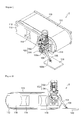
- Fig. 1 is a perspective view of a belt conveyor system 2 provided with a gear motor 100 according to the first embodiment.
- Fig. 2 is a lateral view of the belt conveyor system 2
- the belt conveyor system 2 comprises a conveyor belt 110, a first driven roller 112, a second driven roller 114, a driving roller 116, a first frame 118, a second frame 119, and a torque arm 106.
- the first driven roller 112, the second driven roller 114, and the driving roller 116 are arranged in the stated order so as to be substantially aligned in the horizontal direction.
- the conveyor belt 110 is wound around the three rollers.
- One end of the shaft of each of the first driven roller 112, the second driven roller 114, and the driving roller 116 (the shaft of the first and second driven rollers 112 and 114 is not shown) is rotatably coupled to the first frame 118 via a bearing (not shown).
- the other end of the shaft is rotatably coupled to the second frame 119 via a bearing (not shown).
- the first and second frames 118 and 119 are secured to the floor of a building such as factory in which the belt conveyor system 2 is installed.
- the floor of the building exemplifies an external member outside the system.
- Other examples of the external member include a pillar, a wall, or other equipment.
- the shaft of the driving roller 116 (hereinafter, referred to as a driven shaft) runs through the first frame 118 and so includes a portion (hereinafter, referred to as an exposed portion) exposed on the side of the first frame 118 opposite to the side facing the driving roller 116.
- the gear motor 100 is fitted to the exposed portion of the driven shaft so as to rotate the driving roller 116.
- the gear motor 100 includes a motor 102 and a decelerator 104.
- the motor 102 is an electric motor and is not controlled by an inverter (does not include an inverter).
- the motor 102 is either not operating or operating in response to a prescribed input voltage or a prescribed input power.
- the decelerator 104 is configured to provide perpendicular deceleration.
- the input shaft of the decelerator 104 is substantially perpendicular to the output shaft thereof.
- the decelerator 104 is located between the motor 102 as a power engine and the driving roller 116 as a driven machine.
- the decelerator 104 transmits the rotation of the motor 102 to the driving roller 116.
- the decelerator 104 converts the rotation speed and torque provided by the motor 102 to the input shaft (not shown) of the decelerator 104 into the rotation speed and torque necessary for the driving roller 116.
- the decelerator 104 provides the resulting rotation speed and torque to the driven shaft via the output shaft of the decelerator 104.
- the output shaft of the decelerator 104 is mechanically coupled to the driven shaft. Specifically, the output shaft is coupled to the driven shaft such that rotation of the output shaft relative to the driven shaft is restricted. Such coupling may be implemented by engagement between a key and a key seat.
- a torque arm 106 prevents rotation of the gear motor 100 around the driven shaft.
- the torque arm 106 When the torque arm 106 is removed from the gear motor 100, the angular position of the gear motor 100 relative to the driven shaft becomes unstable.
- the torque arm 106 supports the gear motor 100 so that the angular position of the gear motor 100 relative to the driven shaft remains substantially unchanged.
- the torque arm 106 provides rotation reaction to the gear motor 100.
- the orientation of the gear motor 100 is solely determined by the torque arm 106.
- the gear motor 100 is not directly and mechanically fixed to the external member except for the torque arm 106, the driven shaft, and the electrical wiring to the motor 102.
- One end 106a of the torque arm 106 is bolted to the housing of the decelerator104.
- the other end 106b of the torque arm 106 is bolted to an installation seat 120.
- the installation seat 120 is a plate fixed to the floor of a factory.
- the torque arm 106 is provided with a damper mechanism 108 between the one end 106a and the other end 106b.
- the damper mechanism 108 is capable of exerting a damping force both in the direction in which the torque arm 106 extends and in the direction in which it retracts (the longitudinal direction of the torque arm 106).
- the damper mechanism 108 may be implemented by a hydraulic cylinder, an air cylinder, or a spring. Alternatively, the damper mechanism 108 may be implemented by using a damper technology used in known suspensions.
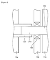
- Fig. 3 shows a cross section of a part in which the output shaft 122 of the decelerator 104 and the driven shaft 124 of the driving roller 116 are coupled.
- the output shaft 122 is a hollow shaft.
- the exposed portion 124a of the driven shaft 124 is inserted into the output shaft 122.
- the driven shaft 124 is rotatably coupled to the first frame 118 via a bearing 126.
- the operator powers the motor 102 on. This applies a voltage of the same level as used in a normal operation to the motor 102 (full voltage starting or line starting).
- a shock load (or a starting torque) of a considerable amount is exerted on the gear motor 100 due to the inertia of the gear inside the decelerator 104 or of the driving roller 116.
- the shock load acts to rotate the gear motor 100 around the driven shaft 124.
- the torque arm 106 supports the gear motor 100 on the floor so as not to cause the gear motor 100 to be rotated due to the shock load.
- the damper mechanism 108 absorbs the shock load or causes the shock load to escape.
- the gear motor 100 is permitted to be rotated slightly around the driven shaft 124 as a result of the damper mechanism 108 extending or retracting. This scatters the shock generated when the motor 102 is started.
- the damper mechanism 108 similarly absorbs the shock load when the belt conveyor system 2 is stopped.
- the shock load generated when the gear motor 100 is started or stopped is absorbed by the damper mechanism 108 and so is reduced. Therefore, adverse impact from the shock load on the gear motor 100 is reduced so that the life of the gear motor 100 is extended.
- the shock load may be relieved by providing an inverter for adjusting the voltage or current supplied to the motor 102 when the motor is started or stopped.
- an inverter is usually more expensive than the damper mechanism 108. Therefore, provision of the damper mechanism 108 according to the embodiment is more cost efficient.
- the method according to the embodiment can easily be applied to existent gear motors.
- the capability to reduce a shock load can be introduced by replacing the existing torque arm supporting the gear motor with the torque arm 106 according to the embodiment.
- the shock load generated when the motor is started or stopped can be further reduced and the shock load generated upon occurrence of emergency shutdown due to sudden power failure can be relieved.
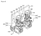
- Fig. 4 is a perspective view of a traveling mechanism 12 provided with a gear motor 200 according to the second embodiment.
- Fig. 5 is a lateral view of the traveling mechanism 12.
- the traveling mechanism 12 is embodied by the wheels of a guided transfer crane and the surrounding parts.
- the traveling mechanism 12 comprises a frame 214, which is a part of the body of the transfer crane, and two traveling parts arranged in the horizontal direction.
- the two traveling parts are basically identically configured so that the following description highlights one of the traveling parts.
- the traveling part includes a wheel 216 compatible with rails (not shown) laid on the ground, a gear motor 200 for driving the wheel 216 into rotation, a first antirotation member, and a second antirotation member.
- the gear motor 200 is attached to the shaft of the wheel 216 so as to rotate the wheel 216.
- the gear motor 200 includes a motor 202 and a decelerator 204.
- the motor 202 and the decelerator 204 correspond to the motor 102 and the decelerator 104 according to the first embodiment, respectively.
- the output shaft of the decelerator 204 is mechanically coupled to the shaft of the wheel 216.
- the first and second antirotation members prevent the gear motor 200 from being rotated around the shaft of the wheel 216.
- Each of the first and second antirotation members is located at a position offset from the center of the output shaft of the decelerator 204 at which it is possible to prevent rotation of the gear motor 200.
- the first antirotation member includes a first antirotation plate 206 and a first spring 210.
- the second antirotation member includes a second antirotation plate 208 and a second spring 212.
- the first and second antirotation plates 206 and 208 are disposed to stand on the frame 214 so as to sandwich the motor 202 between the plates.
- the first spring 210 is attached to the surface of the first antirotation plate 206 facing the motor 202. In other words, the first spring 210 is sandwiched by the motor 202 and the first antirotation plate 206.
- the second spring 212 is attached to the surface of the second antirotation plate 208 facing the motor 202.
- the first spring 210 is positioned to extend and contract in accordance with the distance between the motor 202 and the first antirotation plate 206.
- one end of the first spring 210 is attached to the first antirotation plate 206 and the other end faces the motor 202.
- the gear motor 200 itself is rotated clockwise, the motor 202 approaches the first antirotation plate 206. This causes the first spring 210 to contract until the rotation torque balances the torque from the reaction of the first spring 210.
- the operator powers the motor 202 on. This applies a voltage of the same level as used in a normal operation to the motor 202.
- a shock load of a considerable amount is exerted on the gear motor 200 due to the inertia of the gear inside the decelerator 204 or of the wheel 216.
- the first and second antirotation members support the gear motor 200 on the frame 214 so as not to cause the gear motor 200 to be rotated due to the shock load.
- the first spring 210 or the second spring 212 absorbs the shock load.
- the gear motor 200 is permitted to be rotated slightly around the shaft of the wheel 216 as a result of the first spring 210 or the second spring 212 extending or contracting. This scatters the shock generated when the motor 202 is started. The shock load is similarly absorbed when the traveling mechanism 12 is stopped.
- the gear motor 200 according to the embodiment provides an advantage similar to the advantage provided by the gear motor 100 according to the first embodiment.
- the output shaft of the decelerator is described as being a hollow shaft.
- the output shaft may be a solid shaft.
- two antirotation members are provided by way of example.
- one antirotation member may be provided if the gear motor is assumed to be rotated in one direction.
- the motor is described as not being controlled by an inverter.
- the motor may be controlled by an inverter.
- the antirotation member according to the second embodiment is described as including an antirotation plate and a spring.
- an alternative elastic member e.g., rubber
- the decelerator is described as providing perpendicular deceleration.
- the decelerator may be a parallel shaft decelerator.
Landscapes
- Engineering & Computer Science (AREA)
- Power Engineering (AREA)
- Mechanical Engineering (AREA)
- General Engineering & Computer Science (AREA)
- Connection Of Motors, Electrical Generators, Mechanical Devices, And The Like (AREA)
- Gear Transmission (AREA)
- Motor Or Generator Frames (AREA)
Abstract
Description
- The present invention relates to a gear motor comprising a motor and a decelerator.
- Gear motors are used in an extensive range of applications. For example, gear motors are used in underbody of large-scale movable equipment such as cranes, in a system to drive rollers of a belt conveyor, etc. A gear motor usually comprises a power engine and a decelerator, and is used by coupling an output shaft of the decelerator to a driven shaft of a driven machine.
- Normally, the driven machine is relatively heavy so that it is necessary to provide means to supply rotation reaction to the gear motor in order to prevent the gear motor itself from being rotated when used to drive the machine.
The applicant proposes a technology capable of supplying rotation reaction to the gear motor by means of a torque arm. - When a gear motor is started or stopped, a relatively large shock load is generated due to the inertia of the decelerator gear or of the driven machine. In the conventional technology, a large shock load is directly exerted on the torque arm or the gear motor body so that the torque arm or the gear motor body could be adversely affected.
- The present invention addresses a need to provide a gear motor capable of mitigating a shock load.
- One embodiment of the present invention relates to a gear motor. The gear motor comprises a motor, a decelerator, an output shaft of the decelerator coupled to a driven shaft of a driven machine, and a torque arm for preventing rotation of the gear motor around the driven shaft. One end of the torque arm is fixed to the gear motor and the other end of the torque arm is fixed to an external member. The torque arm is provided with a damper mechanism.
- Another embodiment of the present invention also relates to a gear motor. The gear motor comprises a motor, a decelerator, an output shaft of the decelerator coupled to a driven shaft of a driven machine, and an antirotation member for preventing rotation of the gear motor around the driven shaft. The antirotation member is located at a position offset from the center of output shaft of the decelerator at which it is possible to prevent rotation of the gear motor, and the antirotation member includes an elastic member on a side facing the gear motor.
- Optional combinations of the aforementioned constituting elements, and implementations of the invention in the form of apparatuses, methods, and systems may also be practiced as additional modes of the present invention.
- Embodiments will now be described, by way of example only, with reference to the accompanying drawings which are meant to be exemplary, not limiting, and wherein like elements are numbered alike in several Figures, in which:
-
Fig. 1 is a perspective view of a belt conveyor system provided with a gear motor according to the first embodiment; -
Fig. 2 is a lateral view of the belt conveyor system ofFig. 1 ; -
Fig. 3 shows a cross section of a part in which the output shaft of the decelerator and the driven shaft of the driving roller are coupled; -
Fig. 4 is a perspective view of a traveling mechanism provided with the gear motor according to the second embodiment; and -
Fig. 5 is a lateral view of the traveling mechanism ofFig. 4 . - The invention will now be described by reference to the preferred embodiments. This does not intend to limit the scope of the present invention, but to exemplify the invention.
- Like numerals in the drawings represent like constituting elements or members so that the description is not repeated. For ease of understanding, the dimension of the members in the drawings may be shown on an enlarged or reduced scale as appropriate. Some of the members not important for the purpose of describing the embodiments are not shown in the drawings.
- In a gear motor according to the first embodiment, a damper mechanism is provided in a torque arm for supplying rotation reaction to the gear motor. This can achieve soft start of a gear motor in which a starting torque beyond the motor rating is generated, without electrical control. Since electrical control is not required, the gear motor can be manufactured at a reduced cost.
-
Fig. 1 is a perspective view of abelt conveyor system 2 provided with agear motor 100 according to the first embodiment.Fig. 2 is a lateral view of thebelt conveyor system 2 Thebelt conveyor system 2 comprises aconveyor belt 110, a first drivenroller 112, a second drivenroller 114, adriving roller 116, afirst frame 118, asecond frame 119, and atorque arm 106. - The first driven
roller 112, the second drivenroller 114, and thedriving roller 116 are arranged in the stated order so as to be substantially aligned in the horizontal direction. Theconveyor belt 110 is wound around the three rollers. One end of the shaft of each of the first drivenroller 112, the second drivenroller 114, and the driving roller 116 (the shaft of the first and second drivenrollers first frame 118 via a bearing (not shown). The other end of the shaft is rotatably coupled to thesecond frame 119 via a bearing (not shown). The first andsecond frames belt conveyor system 2 is installed. The floor of the building exemplifies an external member outside the system. Other examples of the external member include a pillar, a wall, or other equipment. - The shaft of the driving roller 116 (hereinafter, referred to as a driven shaft) runs through the
first frame 118 and so includes a portion (hereinafter, referred to as an exposed portion) exposed on the side of thefirst frame 118 opposite to the side facing thedriving roller 116. - The
gear motor 100 is fitted to the exposed portion of the driven shaft so as to rotate thedriving roller 116. Thegear motor 100 includes a motor 102 and adecelerator 104. The motor 102 is an electric motor and is not controlled by an inverter (does not include an inverter). The motor 102 is either not operating or operating in response to a prescribed input voltage or a prescribed input power. Thedecelerator 104 is configured to provide perpendicular deceleration. The input shaft of thedecelerator 104 is substantially perpendicular to the output shaft thereof. - The
decelerator 104 is located between the motor 102 as a power engine and thedriving roller 116 as a driven machine. Thedecelerator 104 transmits the rotation of the motor 102 to thedriving roller 116. In this process, thedecelerator 104 converts the rotation speed and torque provided by the motor 102 to the input shaft (not shown) of thedecelerator 104 into the rotation speed and torque necessary for thedriving roller 116. Thedecelerator 104 provides the resulting rotation speed and torque to the driven shaft via the output shaft of thedecelerator 104. - The output shaft of the
decelerator 104 is mechanically coupled to the driven shaft. Specifically, the output shaft is coupled to the driven shaft such that rotation of the output shaft relative to the driven shaft is restricted. Such coupling may be implemented by engagement between a key and a key seat. - A
torque arm 106 prevents rotation of thegear motor 100 around the driven shaft. When thetorque arm 106 is removed from thegear motor 100, the angular position of thegear motor 100 relative to the driven shaft becomes unstable. Thetorque arm 106 supports thegear motor 100 so that the angular position of thegear motor 100 relative to the driven shaft remains substantially unchanged. Specifically, thetorque arm 106 provides rotation reaction to thegear motor 100. By way of one example, the orientation of thegear motor 100 is solely determined by thetorque arm 106. Thegear motor 100 is not directly and mechanically fixed to the external member except for thetorque arm 106, the driven shaft, and the electrical wiring to the motor 102. - One
end 106a of thetorque arm 106 is bolted to the housing of the decelerator104. Theother end 106b of thetorque arm 106 is bolted to aninstallation seat 120. Theinstallation seat 120 is a plate fixed to the floor of a factory. - The
torque arm 106 is provided with adamper mechanism 108 between the oneend 106a and theother end 106b. Thedamper mechanism 108 is capable of exerting a damping force both in the direction in which thetorque arm 106 extends and in the direction in which it retracts (the longitudinal direction of the torque arm 106). Thedamper mechanism 108 may be implemented by a hydraulic cylinder, an air cylinder, or a spring. Alternatively, thedamper mechanism 108 may be implemented by using a damper technology used in known suspensions. -
Fig. 3 shows a cross section of a part in which theoutput shaft 122 of thedecelerator 104 and the drivenshaft 124 of the drivingroller 116 are coupled. Theoutput shaft 122 is a hollow shaft. The exposedportion 124a of the drivenshaft 124 is inserted into theoutput shaft 122. The drivenshaft 124 is rotatably coupled to thefirst frame 118 via abearing 126. - A description will now be given of the operation of the
gear motor 100 described above. To start thebelt conveyor system 2, the operator powers the motor 102 on.
This applies a voltage of the same level as used in a normal operation to the motor 102 (full voltage starting or line starting). In this process, a shock load (or a starting torque) of a considerable amount is exerted on thegear motor 100 due to the inertia of the gear inside thedecelerator 104 or of the drivingroller 116. The shock load acts to rotate thegear motor 100 around the drivenshaft 124. Thetorque arm 106 supports thegear motor 100 on the floor so as not to cause thegear motor 100 to be rotated due to the shock load. In this process, thedamper mechanism 108 absorbs the shock load or causes the shock load to escape. More specifically, thegear motor 100 is permitted to be rotated slightly around the drivenshaft 124 as a result of thedamper mechanism 108 extending or retracting. This scatters the shock generated when the motor 102 is started. Thedamper mechanism 108 similarly absorbs the shock load when thebelt conveyor system 2 is stopped. - According to the
gear motor 100 of the embodiment, the shock load generated when thegear motor 100 is started or stopped is absorbed by thedamper mechanism 108 and so is reduced. Therefore, adverse impact from the shock load on thegear motor 100 is reduced so that the life of thegear motor 100 is extended. - Instead of providing the
damper mechanism 108, the shock load may be relieved by providing an inverter for adjusting the voltage or current supplied to the motor 102 when the motor is started or stopped. However, such an inverter is usually more expensive than thedamper mechanism 108. Therefore, provision of thedamper mechanism 108 according to the embodiment is more cost efficient. - Another disadvantage with an inverter is that it will be out of operation upon occurrence of sudden power failure. A large shock load generated upon occurrence of emergency shutdown is directly exerted on an inverter-controlled gear motor. In contrast, provision of the
damper mechanism 108 according to the embodiment ensures the shock load generated upon occurrence of emergency shutdown is successfully absorbed because thedamper mechanism 108 continues to be in operation regardless of whether power is fed or not. - The method according to the embodiment can easily be applied to existent gear motors. In other words, the capability to reduce a shock load can be introduced by replacing the existing torque arm supporting the gear motor with the
torque arm 106 according to the embodiment. By additionally providing thetorque arm 106 according to the embodiment in an existing inverter-controlled gear motor, the shock load generated when the motor is started or stopped can be further reduced and the shock load generated upon occurrence of emergency shutdown due to sudden power failure can be relieved. -
Fig. 4 is a perspective view of a travelingmechanism 12 provided with agear motor 200 according to the second embodiment.Fig. 5 is a lateral view of the travelingmechanism 12. In this example, the travelingmechanism 12 is embodied by the wheels of a guided transfer crane and the surrounding parts. The travelingmechanism 12 comprises aframe 214, which is a part of the body of the transfer crane, and two traveling parts arranged in the horizontal direction. The two traveling parts are basically identically configured so that the following description highlights one of the traveling parts. - The traveling part includes a
wheel 216 compatible with rails (not shown) laid on the ground, agear motor 200 for driving thewheel 216 into rotation, a first antirotation member, and a second antirotation member. Thegear motor 200 is attached to the shaft of thewheel 216 so as to rotate thewheel 216. Thegear motor 200 includes amotor 202 and adecelerator 204. Themotor 202 and thedecelerator 204 correspond to the motor 102 and thedecelerator 104 according to the first embodiment, respectively. The output shaft of thedecelerator 204 is mechanically coupled to the shaft of thewheel 216. - The first and second antirotation members prevent the
gear motor 200 from being rotated around the shaft of thewheel 216. Each of the first and second antirotation members is located at a position offset from the center of the output shaft of thedecelerator 204 at which it is possible to prevent rotation of thegear motor 200. - The first antirotation member includes a
first antirotation plate 206 and afirst spring 210. The second antirotation member includes asecond antirotation plate 208 and asecond spring 212. The first andsecond antirotation plates frame 214 so as to sandwich themotor 202 between the plates. Thefirst spring 210 is attached to the surface of thefirst antirotation plate 206 facing themotor 202. In other words, thefirst spring 210 is sandwiched by themotor 202 and thefirst antirotation plate 206. Thesecond spring 212 is attached to the surface of thesecond antirotation plate 208 facing themotor 202. - The
first spring 210 is positioned to extend and contract in accordance with the distance between themotor 202 and thefirst antirotation plate 206. In particular, one end of thefirst spring 210 is attached to thefirst antirotation plate 206 and the other end faces themotor 202. Referring toFig. 5 , when thegear motor 200 itself is rotated clockwise, themotor 202 approaches thefirst antirotation plate 206. This causes thefirst spring 210 to contract until the rotation torque balances the torque from the reaction of thefirst spring 210. A similar situation holds true of thesecond spring 212. - A description will now be given of the operation of the
gear motor 200 configured as described above. To start the travelingmechanism 12, the operator powers themotor 202 on. This applies a voltage of the same level as used in a normal operation to themotor 202. In this process, a shock load of a considerable amount is exerted on thegear motor 200 due to the inertia of the gear inside thedecelerator 204 or of thewheel 216. The first and second antirotation members support thegear motor 200 on theframe 214 so as not to cause thegear motor 200 to be rotated due to the shock load. In this process, thefirst spring 210 or thesecond spring 212 absorbs the shock load. More specifically, thegear motor 200 is permitted to be rotated slightly around the shaft of thewheel 216 as a result of thefirst spring 210 or thesecond spring 212 extending or contracting. This scatters the shock generated when themotor 202 is started. The shock load is similarly absorbed when the travelingmechanism 12 is stopped. - The
gear motor 200 according to the embodiment provides an advantage similar to the advantage provided by thegear motor 100 according to the first embodiment. - Described above is the configuration and operation of the gear motor according to the embodiments. The embodiment is intended to be illustrative only and it will be obvious to those skilled in the art that various modifications to constituting elements could be developed and that such modifications are also within the scope of the present invention.
- In the first and second embodiments, the output shaft of the decelerator is described as being a hollow shaft. Alternatively, the output shaft may be a solid shaft.
- In the second embodiment, two antirotation members are provided by way of example. Alternatively, one antirotation member may be provided if the gear motor is assumed to be rotated in one direction.
- In the first and second embodiments, the motor is described as not being controlled by an inverter. Alternatively, the motor may be controlled by an inverter.
- The antirotation member according to the second embodiment is described as including an antirotation plate and a spring. Alternatively, an alternative elastic member (e.g., rubber) may be used in place of the spring.
- In the first and second embodiments, the decelerator is described as providing perpendicular deceleration. Alternatively, the decelerator may be a parallel shaft decelerator.
- Priority is claimed to Japanese Patent Application No.
2012-285149, filed December 27, 2012
Claims (6)
- A gear motor (100) comprising:a motor (102);a decelerator (104);an output shaft of the decelerator (104) coupled to a driven shaft of a driven machine; anda torque arm (106) for preventing rotation of the gear motor (100) around the driven shaft;wherein one end (106a) of the torque arm (106) is fixed to the gear motor (100), the other end (106b) of the torque arm (106) is fixed to an external member, and the torque arm (106) is provided with a damper mechanism (108).
- The gear motor (100) according to claim 1, wherein the damper mechanism (108) exerts a damping force both in a direction in which the torque arm (106) extends and in a direction in which the torque arm (106) retracts.
- A gear motor (100) comprising:a motor (102);a decelerator (104);an output shaft of the decelerator (104) coupled to a driven shaft of a driven machine; andan antirotation member for preventing rotation of the gear motor (100) around the driven shaft,wherein the antirotation member is located at a position offset from the center of output shaft of the decelerator (104) at which it is possible to prevent rotation of the gear motor (100), and the antirotation member includes an elastic member on a side facing the gear motor (100).
- The gear motor (100) according to claim 3,
wherein the decelerator (104) is configured to provide perpendicular deceleration, and
wherein the elastic member faces the motor (102). - The gear motor (100) according to one of claims 1 through 4,
wherein the output shaft of the decelerator (104) is a hollow shaft, and the driven shaft is inserted into the output shaft. - The gear motor (100) according to one of claims 1 through 5,
wherein the motor (102) is not controlled by an inverter.
Applications Claiming Priority (1)
| Application Number | Priority Date | Filing Date | Title |
|---|---|---|---|
| JP2012285149A JP5985385B2 (en) | 2012-12-27 | 2012-12-27 | Gear motor |
Publications (2)
| Publication Number | Publication Date |
|---|---|
| EP2749791A1 true EP2749791A1 (en) | 2014-07-02 |
| EP2749791B1 EP2749791B1 (en) | 2016-07-27 |
Family
ID=49356178
Family Applications (1)
| Application Number | Title | Priority Date | Filing Date |
|---|---|---|---|
| EP13020116.3A Not-in-force EP2749791B1 (en) | 2012-12-27 | 2013-10-08 | Gear motor |
Country Status (4)
| Country | Link |
|---|---|
| US (1) | US9260250B2 (en) |
| EP (1) | EP2749791B1 (en) |
| JP (1) | JP5985385B2 (en) |
| CN (1) | CN103904822B (en) |
Families Citing this family (2)
| Publication number | Priority date | Publication date | Assignee | Title |
|---|---|---|---|---|
| US11358800B2 (en) * | 2018-05-09 | 2022-06-14 | Sew-Eurodrive Gmbh & Co. Kg | Standardized modular drive assembly |
| CN113955406B (en) * | 2021-11-26 | 2023-07-21 | 中煤科工集团上海有限公司 | High-power explosion-proof integrated permanent magnet roller driving system for belt conveyor |
Citations (3)
| Publication number | Priority date | Publication date | Assignee | Title |
|---|---|---|---|---|
| DE1091829B (en) * | 1956-01-03 | 1960-10-27 | American Pulley Company | Torque limiter |
| DE4327533C1 (en) * | 1993-08-10 | 1995-01-05 | Mannesmann Ag | Driving device with a torque reaction bar |
| DE102008030192A1 (en) * | 2008-06-25 | 2009-12-31 | Sms Siemag Aktiengesellschaft | Torque support for a converter tipping drive |
Family Cites Families (24)
| Publication number | Priority date | Publication date | Assignee | Title |
|---|---|---|---|---|
| US2984336A (en) * | 1957-11-27 | 1961-05-16 | Fmc Corp | Conveyor drive mechanism |
| US3456605A (en) * | 1967-10-09 | 1969-07-22 | Ver Kesselwerke Ag | Torque-compensating supporting arrangement |
| US3980170A (en) * | 1974-12-23 | 1976-09-14 | Reliance Electric Company | Drive system for an annealing lehr |
| DE3504751A1 (en) * | 1985-02-08 | 1986-08-14 | Bellheimer Metallwerk GmbH, 6729 Bellheim | CIRCULAR SHELF |
| US4723455A (en) * | 1986-10-10 | 1988-02-09 | Reliance Electric Company | Mechanical variable speed drive |
| JP2769323B2 (en) * | 1988-06-29 | 1998-06-25 | アイシン・エィ・ダブリュ株式会社 | Motor drive device with reduction gear and electric vehicle |
| JP2877362B2 (en) * | 1989-07-19 | 1999-03-31 | キヤノン株式会社 | Motor support device |
| US5115908A (en) * | 1990-04-27 | 1992-05-26 | Williams John C | Package handling conveyor system |
| DE4102424C3 (en) * | 1991-01-28 | 2000-08-24 | Telair Int Gmbh | Drive roller unit |
| JP3197784B2 (en) * | 1995-04-12 | 2001-08-13 | 株式会社白山機工 | Overload stop mechanism for shaft mounted motor |
| JP3613857B2 (en) * | 1995-11-16 | 2005-01-26 | 文化シヤッター株式会社 | Winding shaft drive structure of switchgear |
| JP2003299295A (en) * | 2002-03-29 | 2003-10-17 | Sumitomo Heavy Ind Ltd | Geared motor fastening structure and torque arm manufacturing method |
| DE10228026A1 (en) * | 2002-06-24 | 2004-01-22 | Bleichert Förderanlagen GmbH | Transport device with hysteresis clutch |
| KR100688185B1 (en) * | 2004-05-28 | 2007-03-02 | 엘지전자 주식회사 | Variable speed motor |
| JP4793809B2 (en) * | 2004-09-02 | 2011-10-12 | 東京エレクトロン株式会社 | Heavy object turning mechanism |
| JP4736402B2 (en) * | 2004-11-02 | 2011-07-27 | 日産自動車株式会社 | Motor built-in suspension device and electric vehicle equipped with the same |
| US20060237602A1 (en) * | 2005-04-26 | 2006-10-26 | Boston Gear, Llc | Conveyor flange adapter |
| KR100695631B1 (en) * | 2006-02-03 | 2007-03-16 | 삼성전기주식회사 | Display rotator |
| US20080271970A1 (en) * | 2007-05-03 | 2008-11-06 | David Pearson Stoltze | Torque arm assembly for a backstopping clutch |
| DE102008000891A1 (en) * | 2008-03-31 | 2009-10-01 | Robert Bosch Gmbh | Protection system for machine tools |
| JP5267219B2 (en) * | 2008-06-30 | 2013-08-21 | 株式会社リコー | Deceleration device, rotating body driving device, image carrier driving device, and image forming apparatus |
| CN101628486B (en) * | 2009-08-07 | 2012-02-15 | 湖州机床厂有限公司 | Drive device of movable working platform |
| US8292218B2 (en) * | 2010-06-17 | 2012-10-23 | Goodrich Corporation | Torque link with shimmy damper |
| US8558429B2 (en) * | 2011-01-05 | 2013-10-15 | General Electric Company | Systems, methods, and apparatus for lifting brushes of an induction motor |
-
2012
- 2012-12-27 JP JP2012285149A patent/JP5985385B2/en active Active
-
2013
- 2013-09-25 CN CN201310441746.1A patent/CN103904822B/en not_active Expired - Fee Related
- 2013-10-08 EP EP13020116.3A patent/EP2749791B1/en not_active Not-in-force
- 2013-10-18 US US14/057,420 patent/US9260250B2/en not_active Expired - Fee Related
Patent Citations (3)
| Publication number | Priority date | Publication date | Assignee | Title |
|---|---|---|---|---|
| DE1091829B (en) * | 1956-01-03 | 1960-10-27 | American Pulley Company | Torque limiter |
| DE4327533C1 (en) * | 1993-08-10 | 1995-01-05 | Mannesmann Ag | Driving device with a torque reaction bar |
| DE102008030192A1 (en) * | 2008-06-25 | 2009-12-31 | Sms Siemag Aktiengesellschaft | Torque support for a converter tipping drive |
Also Published As
| Publication number | Publication date |
|---|---|
| EP2749791B1 (en) | 2016-07-27 |
| CN103904822B (en) | 2018-03-30 |
| US9260250B2 (en) | 2016-02-16 |
| CN103904822A (en) | 2014-07-02 |
| US20140183997A1 (en) | 2014-07-03 |
| JP2014128168A (en) | 2014-07-07 |
| JP5985385B2 (en) | 2016-09-06 |
Similar Documents
| Publication | Publication Date | Title |
|---|---|---|
| TWI306078B (en) | Drive engine for a lift installation and method of mounting a drive engine | |
| US10005644B2 (en) | Machine for driving a lift | |
| CN101423167B (en) | Elevator and winch and motor used for the elevator | |
| KR20190041855A (en) | Steering system for in-wheel motor vehicle | |
| US12534114B2 (en) | Electric-powered vehicle | |
| CN101896417A (en) | Elevator machine frame | |
| US9260250B2 (en) | Gear motor having an antirotation member | |
| JP2020079528A (en) | Electric small-sized roller | |
| CN108890613A (en) | A kind of driving wheel apparatus for heavy load climbing robot | |
| JP2023506644A (en) | Drive system for elevator installation, elevator installation and method for installing drive on support elements of elevator installation | |
| CN100443395C (en) | Device for adjusting the steering angle of elevator pulleys | |
| KR102375667B1 (en) | sheet conveying device | |
| US9897191B2 (en) | Torque arm structure | |
| KR102849191B1 (en) | Differential drive device and automatic guided transport vehicle | |
| JP5300990B2 (en) | Elevator hoisting machine and method of manufacturing elevator hoisting machine | |
| JP2007325426A (en) | Cantilevered rotary motor | |
| CN206108601U (en) | Elevator manual turning device | |
| JP6033091B2 (en) | Drive device | |
| EP4068587A1 (en) | Rotary electric machine | |
| JP2000310261A (en) | lift device | |
| JP4129901B2 (en) | Elevator equipment | |
| CN224090033U (en) | Omnidirectional mobile chassis | |
| CN223073246U (en) | Multi-drive electric roller and conveying equipment | |
| CN223237365U (en) | An omnidirectional motion chassis and AGV equipment | |
| CN223316099U (en) | Pass roller and electric core lamination machine's diaphragm area way |
Legal Events
| Date | Code | Title | Description |
|---|---|---|---|
| 17P | Request for examination filed |
Effective date: 20131008 |
|
| AK | Designated contracting states |
Kind code of ref document: A1 Designated state(s): AL AT BE BG CH CY CZ DE DK EE ES FI FR GB GR HR HU IE IS IT LI LT LU LV MC MK MT NL NO PL PT RO RS SE SI SK SM TR |
|
| AX | Request for extension of the european patent |
Extension state: BA ME |
|
| PUAI | Public reference made under article 153(3) epc to a published international application that has entered the european phase |
Free format text: ORIGINAL CODE: 0009012 |
|
| RBV | Designated contracting states (corrected) |
Designated state(s): AL AT BE BG CH CY CZ DE DK EE ES FI FR GB GR HR HU IE IS IT LI LT LU LV MC MK MT NL NO PL PT RO RS SE SI SK SM TR |
|
| 17Q | First examination report despatched |
Effective date: 20150521 |
|
| GRAP | Despatch of communication of intention to grant a patent |
Free format text: ORIGINAL CODE: EPIDOSNIGR1 |
|
| INTG | Intention to grant announced |
Effective date: 20160225 |
|
| GRAS | Grant fee paid |
Free format text: ORIGINAL CODE: EPIDOSNIGR3 |
|
| GRAA | (expected) grant |
Free format text: ORIGINAL CODE: 0009210 |
|
| AK | Designated contracting states |
Kind code of ref document: B1 Designated state(s): AL AT BE BG CH CY CZ DE DK EE ES FI FR GB GR HR HU IE IS IT LI LT LU LV MC MK MT NL NO PL PT RO RS SE SI SK SM TR |
|
| REG | Reference to a national code |
Ref country code: GB Ref legal event code: FG4D |
|
| REG | Reference to a national code |
Ref country code: CH Ref legal event code: EP |
|
| REG | Reference to a national code |
Ref country code: AT Ref legal event code: REF Ref document number: 816078 Country of ref document: AT Kind code of ref document: T Effective date: 20160815 |
|
| REG | Reference to a national code |
Ref country code: IE Ref legal event code: FG4D |
|
| REG | Reference to a national code |
Ref country code: DE Ref legal event code: R096 Ref document number: 602013009744 Country of ref document: DE |
|
| REG | Reference to a national code |
Ref country code: LT Ref legal event code: MG4D |
|
| REG | Reference to a national code |
Ref country code: NL Ref legal event code: MP Effective date: 20160727 |
|
| REG | Reference to a national code |
Ref country code: AT Ref legal event code: MK05 Ref document number: 816078 Country of ref document: AT Kind code of ref document: T Effective date: 20160727 |
|
| PG25 | Lapsed in a contracting state [announced via postgrant information from national office to epo] |
Ref country code: HR Free format text: LAPSE BECAUSE OF FAILURE TO SUBMIT A TRANSLATION OF THE DESCRIPTION OR TO PAY THE FEE WITHIN THE PRESCRIBED TIME-LIMIT Effective date: 20160727 Ref country code: LT Free format text: LAPSE BECAUSE OF FAILURE TO SUBMIT A TRANSLATION OF THE DESCRIPTION OR TO PAY THE FEE WITHIN THE PRESCRIBED TIME-LIMIT Effective date: 20160727 Ref country code: RS Free format text: LAPSE BECAUSE OF FAILURE TO SUBMIT A TRANSLATION OF THE DESCRIPTION OR TO PAY THE FEE WITHIN THE PRESCRIBED TIME-LIMIT Effective date: 20160727 Ref country code: FI Free format text: LAPSE BECAUSE OF FAILURE TO SUBMIT A TRANSLATION OF THE DESCRIPTION OR TO PAY THE FEE WITHIN THE PRESCRIBED TIME-LIMIT Effective date: 20160727 Ref country code: NL Free format text: LAPSE BECAUSE OF FAILURE TO SUBMIT A TRANSLATION OF THE DESCRIPTION OR TO PAY THE FEE WITHIN THE PRESCRIBED TIME-LIMIT Effective date: 20160727 Ref country code: IS Free format text: LAPSE BECAUSE OF FAILURE TO SUBMIT A TRANSLATION OF THE DESCRIPTION OR TO PAY THE FEE WITHIN THE PRESCRIBED TIME-LIMIT Effective date: 20161127 Ref country code: IT Free format text: LAPSE BECAUSE OF FAILURE TO SUBMIT A TRANSLATION OF THE DESCRIPTION OR TO PAY THE FEE WITHIN THE PRESCRIBED TIME-LIMIT Effective date: 20160727 Ref country code: NO Free format text: LAPSE BECAUSE OF FAILURE TO SUBMIT A TRANSLATION OF THE DESCRIPTION OR TO PAY THE FEE WITHIN THE PRESCRIBED TIME-LIMIT Effective date: 20161027 |
|
| PG25 | Lapsed in a contracting state [announced via postgrant information from national office to epo] |
Ref country code: GR Free format text: LAPSE BECAUSE OF FAILURE TO SUBMIT A TRANSLATION OF THE DESCRIPTION OR TO PAY THE FEE WITHIN THE PRESCRIBED TIME-LIMIT Effective date: 20161028 Ref country code: SE Free format text: LAPSE BECAUSE OF FAILURE TO SUBMIT A TRANSLATION OF THE DESCRIPTION OR TO PAY THE FEE WITHIN THE PRESCRIBED TIME-LIMIT Effective date: 20160727 Ref country code: AT Free format text: LAPSE BECAUSE OF FAILURE TO SUBMIT A TRANSLATION OF THE DESCRIPTION OR TO PAY THE FEE WITHIN THE PRESCRIBED TIME-LIMIT Effective date: 20160727 Ref country code: PT Free format text: LAPSE BECAUSE OF FAILURE TO SUBMIT A TRANSLATION OF THE DESCRIPTION OR TO PAY THE FEE WITHIN THE PRESCRIBED TIME-LIMIT Effective date: 20161128 Ref country code: ES Free format text: LAPSE BECAUSE OF FAILURE TO SUBMIT A TRANSLATION OF THE DESCRIPTION OR TO PAY THE FEE WITHIN THE PRESCRIBED TIME-LIMIT Effective date: 20160727 Ref country code: LV Free format text: LAPSE BECAUSE OF FAILURE TO SUBMIT A TRANSLATION OF THE DESCRIPTION OR TO PAY THE FEE WITHIN THE PRESCRIBED TIME-LIMIT Effective date: 20160727 Ref country code: BE Free format text: LAPSE BECAUSE OF NON-PAYMENT OF DUE FEES Effective date: 20160727 Ref country code: PL Free format text: LAPSE BECAUSE OF FAILURE TO SUBMIT A TRANSLATION OF THE DESCRIPTION OR TO PAY THE FEE WITHIN THE PRESCRIBED TIME-LIMIT Effective date: 20160727 |
|
| PG25 | Lapsed in a contracting state [announced via postgrant information from national office to epo] |
Ref country code: EE Free format text: LAPSE BECAUSE OF FAILURE TO SUBMIT A TRANSLATION OF THE DESCRIPTION OR TO PAY THE FEE WITHIN THE PRESCRIBED TIME-LIMIT Effective date: 20160727 Ref country code: RO Free format text: LAPSE BECAUSE OF FAILURE TO SUBMIT A TRANSLATION OF THE DESCRIPTION OR TO PAY THE FEE WITHIN THE PRESCRIBED TIME-LIMIT Effective date: 20160727 |
|
| REG | Reference to a national code |
Ref country code: DE Ref legal event code: R097 Ref document number: 602013009744 Country of ref document: DE |
|
| PG25 | Lapsed in a contracting state [announced via postgrant information from national office to epo] |
Ref country code: DK Free format text: LAPSE BECAUSE OF FAILURE TO SUBMIT A TRANSLATION OF THE DESCRIPTION OR TO PAY THE FEE WITHIN THE PRESCRIBED TIME-LIMIT Effective date: 20160727 Ref country code: SK Free format text: LAPSE BECAUSE OF FAILURE TO SUBMIT A TRANSLATION OF THE DESCRIPTION OR TO PAY THE FEE WITHIN THE PRESCRIBED TIME-LIMIT Effective date: 20160727 Ref country code: CZ Free format text: LAPSE BECAUSE OF FAILURE TO SUBMIT A TRANSLATION OF THE DESCRIPTION OR TO PAY THE FEE WITHIN THE PRESCRIBED TIME-LIMIT Effective date: 20160727 Ref country code: BG Free format text: LAPSE BECAUSE OF FAILURE TO SUBMIT A TRANSLATION OF THE DESCRIPTION OR TO PAY THE FEE WITHIN THE PRESCRIBED TIME-LIMIT Effective date: 20161027 Ref country code: SM Free format text: LAPSE BECAUSE OF FAILURE TO SUBMIT A TRANSLATION OF THE DESCRIPTION OR TO PAY THE FEE WITHIN THE PRESCRIBED TIME-LIMIT Effective date: 20160727 |
|
| REG | Reference to a national code |
Ref country code: CH Ref legal event code: PL |
|
| PLBE | No opposition filed within time limit |
Free format text: ORIGINAL CODE: 0009261 |
|
| STAA | Information on the status of an ep patent application or granted ep patent |
Free format text: STATUS: NO OPPOSITION FILED WITHIN TIME LIMIT |
|
| 26N | No opposition filed |
Effective date: 20170502 |
|
| REG | Reference to a national code |
Ref country code: IE Ref legal event code: MM4A |
|
| REG | Reference to a national code |
Ref country code: FR Ref legal event code: ST Effective date: 20170630 |
|
| PG25 | Lapsed in a contracting state [announced via postgrant information from national office to epo] |
Ref country code: LI Free format text: LAPSE BECAUSE OF NON-PAYMENT OF DUE FEES Effective date: 20161031 Ref country code: FR Free format text: LAPSE BECAUSE OF NON-PAYMENT OF DUE FEES Effective date: 20161102 Ref country code: CH Free format text: LAPSE BECAUSE OF NON-PAYMENT OF DUE FEES Effective date: 20161031 |
|
| PG25 | Lapsed in a contracting state [announced via postgrant information from national office to epo] |
Ref country code: SI Free format text: LAPSE BECAUSE OF FAILURE TO SUBMIT A TRANSLATION OF THE DESCRIPTION OR TO PAY THE FEE WITHIN THE PRESCRIBED TIME-LIMIT Effective date: 20160727 Ref country code: LU Free format text: LAPSE BECAUSE OF NON-PAYMENT OF DUE FEES Effective date: 20161008 |
|
| PG25 | Lapsed in a contracting state [announced via postgrant information from national office to epo] |
Ref country code: IE Free format text: LAPSE BECAUSE OF NON-PAYMENT OF DUE FEES Effective date: 20161008 |
|
| PG25 | Lapsed in a contracting state [announced via postgrant information from national office to epo] |
Ref country code: HU Free format text: LAPSE BECAUSE OF FAILURE TO SUBMIT A TRANSLATION OF THE DESCRIPTION OR TO PAY THE FEE WITHIN THE PRESCRIBED TIME-LIMIT; INVALID AB INITIO Effective date: 20131008 |
|
| GBPC | Gb: european patent ceased through non-payment of renewal fee |
Effective date: 20171008 |
|
| PG25 | Lapsed in a contracting state [announced via postgrant information from national office to epo] |
Ref country code: MT Free format text: LAPSE BECAUSE OF NON-PAYMENT OF DUE FEES Effective date: 20161031 Ref country code: CY Free format text: LAPSE BECAUSE OF FAILURE TO SUBMIT A TRANSLATION OF THE DESCRIPTION OR TO PAY THE FEE WITHIN THE PRESCRIBED TIME-LIMIT Effective date: 20160727 Ref country code: MK Free format text: LAPSE BECAUSE OF FAILURE TO SUBMIT A TRANSLATION OF THE DESCRIPTION OR TO PAY THE FEE WITHIN THE PRESCRIBED TIME-LIMIT Effective date: 20160727 Ref country code: MC Free format text: LAPSE BECAUSE OF FAILURE TO SUBMIT A TRANSLATION OF THE DESCRIPTION OR TO PAY THE FEE WITHIN THE PRESCRIBED TIME-LIMIT Effective date: 20160727 |
|
| PG25 | Lapsed in a contracting state [announced via postgrant information from national office to epo] |
Ref country code: GB Free format text: LAPSE BECAUSE OF NON-PAYMENT OF DUE FEES Effective date: 20171008 |
|
| PG25 | Lapsed in a contracting state [announced via postgrant information from national office to epo] |
Ref country code: TR Free format text: LAPSE BECAUSE OF FAILURE TO SUBMIT A TRANSLATION OF THE DESCRIPTION OR TO PAY THE FEE WITHIN THE PRESCRIBED TIME-LIMIT Effective date: 20160727 Ref country code: AL Free format text: LAPSE BECAUSE OF FAILURE TO SUBMIT A TRANSLATION OF THE DESCRIPTION OR TO PAY THE FEE WITHIN THE PRESCRIBED TIME-LIMIT Effective date: 20160727 |
|
| PGFP | Annual fee paid to national office [announced via postgrant information from national office to epo] |
Ref country code: DE Payment date: 20220831 Year of fee payment: 10 |
|
| REG | Reference to a national code |
Ref country code: DE Ref legal event code: R119 Ref document number: 602013009744 Country of ref document: DE |
|
| PG25 | Lapsed in a contracting state [announced via postgrant information from national office to epo] |
Ref country code: DE Free format text: LAPSE BECAUSE OF NON-PAYMENT OF DUE FEES Effective date: 20240501 |