EP2749380A1 - Hammer drill - Google Patents
Hammer drill Download PDFInfo
- Publication number
- EP2749380A1 EP2749380A1 EP13195545.2A EP13195545A EP2749380A1 EP 2749380 A1 EP2749380 A1 EP 2749380A1 EP 13195545 A EP13195545 A EP 13195545A EP 2749380 A1 EP2749380 A1 EP 2749380A1
- Authority
- EP
- European Patent Office
- Prior art keywords
- clutch
- hammer drill
- transfer member
- intermediate shaft
- engages
- Prior art date
- Legal status (The legal status is an assumption and is not a legal conclusion. Google has not performed a legal analysis and makes no representation as to the accuracy of the status listed.)
- Granted
Links
- 239000002184 metal Substances 0.000 claims description 3
- 230000000694 effects Effects 0.000 description 6
- 230000007935 neutral effect Effects 0.000 description 6
- 230000000717 retained effect Effects 0.000 description 3
- 230000020169 heat generation Effects 0.000 description 2
- 230000004048 modification Effects 0.000 description 2
- 238000012986 modification Methods 0.000 description 2
- 230000003116 impacting effect Effects 0.000 description 1
- 238000003780 insertion Methods 0.000 description 1
- 230000037431 insertion Effects 0.000 description 1
- 230000014759 maintenance of location Effects 0.000 description 1
- 230000002093 peripheral effect Effects 0.000 description 1
Images


Classifications
-
- F—MECHANICAL ENGINEERING; LIGHTING; HEATING; WEAPONS; BLASTING
- F16—ENGINEERING ELEMENTS AND UNITS; GENERAL MEASURES FOR PRODUCING AND MAINTAINING EFFECTIVE FUNCTIONING OF MACHINES OR INSTALLATIONS; THERMAL INSULATION IN GENERAL
- F16D—COUPLINGS FOR TRANSMITTING ROTATION; CLUTCHES; BRAKES
- F16D21/00—Systems comprising a plurality of actuated clutches
-
- B—PERFORMING OPERATIONS; TRANSPORTING
- B25—HAND TOOLS; PORTABLE POWER-DRIVEN TOOLS; MANIPULATORS
- B25D—PERCUSSIVE TOOLS
- B25D16/00—Portable percussive machines with superimposed rotation, the rotational movement of the output shaft of a motor being modified to generate axial impacts on the tool bit
- B25D16/003—Clutches specially adapted therefor
-
- B—PERFORMING OPERATIONS; TRANSPORTING
- B25—HAND TOOLS; PORTABLE POWER-DRIVEN TOOLS; MANIPULATORS
- B25D—PERCUSSIVE TOOLS
- B25D2216/00—Details of portable percussive machines with superimposed rotation, the rotational movement of the output shaft of a motor being modified to generate axial impacts on the tool bit
- B25D2216/0007—Details of percussion or rotation modes
- B25D2216/0015—Tools having a percussion-only mode
-
- B—PERFORMING OPERATIONS; TRANSPORTING
- B25—HAND TOOLS; PORTABLE POWER-DRIVEN TOOLS; MANIPULATORS
- B25D—PERCUSSIVE TOOLS
- B25D2216/00—Details of portable percussive machines with superimposed rotation, the rotational movement of the output shaft of a motor being modified to generate axial impacts on the tool bit
- B25D2216/0007—Details of percussion or rotation modes
- B25D2216/0023—Tools having a percussion-and-rotation mode
-
- B—PERFORMING OPERATIONS; TRANSPORTING
- B25—HAND TOOLS; PORTABLE POWER-DRIVEN TOOLS; MANIPULATORS
- B25D—PERCUSSIVE TOOLS
- B25D2216/00—Details of portable percussive machines with superimposed rotation, the rotational movement of the output shaft of a motor being modified to generate axial impacts on the tool bit
- B25D2216/0007—Details of percussion or rotation modes
- B25D2216/0038—Tools having a rotation-only mode
-
- B—PERFORMING OPERATIONS; TRANSPORTING
- B25—HAND TOOLS; PORTABLE POWER-DRIVEN TOOLS; MANIPULATORS
- B25D—PERCUSSIVE TOOLS
- B25D2216/00—Details of portable percussive machines with superimposed rotation, the rotational movement of the output shaft of a motor being modified to generate axial impacts on the tool bit
- B25D2216/0084—Mode-changing mechanisms
-
- B—PERFORMING OPERATIONS; TRANSPORTING
- B25—HAND TOOLS; PORTABLE POWER-DRIVEN TOOLS; MANIPULATORS
- B25D—PERCUSSIVE TOOLS
- B25D2250/00—General details of portable percussive tools; Components used in portable percussive tools
- B25D2250/371—Use of springs
Definitions
- the present invention relates to a hammer drill that enables selecting one of at least three operation modes including a hammer mode, a hammer drill mode, and a drill mode.
- an intermediate shaft is interposed between an output shaft of a motor and a tool holder that holds a bit.
- An impact transfer member and a rotation transfer member are each rotatably provided on the intermediate shaft.
- the impact transfer member transfers an impact to the bit.
- the rotation transfer member transfers rotation to the tool holder.
- a clutch is provided between the impact transfer member and the rotation transfer member. The clutch is rotatable together with the intermediate shaft, and movable in the axial direction. One of operation modes is selectable by an operation of sliding the clutch performed from outside a housing.
- two clutches are provided, namely a first clutch (first sleeve) capable of engaging with only the impact transfer member and a second clutch (second sleeve) capable of engaging with only the rotation transfer member.
- first clutch first sleeve
- second clutch second sleeve
- One coil spring serving as an elastic element is interposed between the clutches to urge the clutches in directions away from each other.
- One of the three operation modes described above is selectable by sliding a plate that engages with the clutches in the axial direction of the intermediate shaft from outside the housing.
- a first aspect of the present invention provides a hammer drill characterized in that an elastic element, which urges a first clutch and a second clutch, is held between a first clutch operation member and a second clutch operation member.
- the first clutch operation member engages with the first clutch to be slidable in the axial direction of the intermediate shaft.
- the second clutch operation member engages with the second clutch to be slidable in the axial direction of the intermediate shaft.
- At least one of the first and second clutch operation members is slidably guided by the housing or the intermediate shaft.
- a second aspect of the present invention provides the hammer drill according to the first aspect, in which one of the first and second clutch operation members is guided by the housing or the intermediate shaft, and the other is guided by the one of the clutch operation members.
- a third aspect of the present invention provides the hammer drill according to the first or second aspect, in which the first and second clutch operation members are provided with respective restraint portions that abut against each other to restrain slide due to urging by the elastic element.
- a fourth aspect of the present invention provides the hammer drill according to the third aspect, in which the elastic element is compressed in a state where the restraint portions restrain slide.
- a fifth aspect of the present invention provides the hammer drill according to any one of the first to fourth aspects, in which the housing is provided with respective positioning portions that restrain slide of the first and second clutch operation members at a position at which the first clutch engages with the impact transfer member and the second clutch engages with the rotation transfer member.
- a sixth aspect of the present invention provides the hammer drill according to the first aspect, in which the first and second clutch operation members are each guided by the housing.
- a seventh aspect of the present invention provides the hammer drill according to any one of the first to sixth aspects, in which the first clutch and the second clutch have the same shape.
- the first aspect of the present invention it is possible to provide a hammer drill that can be made compact with no need for a long intermediate shaft even if two clutches, namely the first and second clutches, are used.
- one of the clutch operation members is guided by the other.
- the structure is expected to be simplified with no need for a guide member for the one of the clutch operation members.
- the adoption of the restraint portions enables the first and second clutch operation members to be properly assembled. Accordingly, the ease of assembly of the clutch operation members is improved.
- the elastic element is prevented from slipping off with the first and second clutch operation members in the assembled state.
- the ease of assembly of the elastic element is improved.
- the adoption of the positioning portions allows the first clutch and the second clutch to engage with the impact transfer member and the rotation transfer member, respectively, at a proper position and without being pressed. Thus, heat generation is prevented.
- the clutch operation members are allowed to slide with the same sliding performance.
- the assembly is facilitated, and the trouble of part management is reduced.
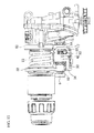
- FIG. 1 is a partial vertical sectional view of an example of a hammer drill.
- a motor 3 is accommodated in a motor housing (not illustrated) so as to be directed upward in the lower portion of the rear (with the right side of FIG. 1 defined as the front) of a gear housing 2 serving as a housing.
- An output shaft 4 of the motor 3 is supported by an inner housing 6 assembled to the rear portion in the gear housing 2.
- the output shaft 4 extends into the gear housing 2.
- An intermediate shaft 7 is disposed in the front-rear direction above the output shaft 4 and between the gear housing 2 and the inner housing 6.
- the intermediate shaft 7 is rotatably supported by ball bearings 8 and 9 at the front and rear ends, respectively.
- a bevel gear 10 fixed to the rear portion of the intermediate shaft 7 is meshed with a pinion 5 fixed to the distal end of the output shaft 4.
- a boss sleeve 11 serving as an impact transfer member is rotatably provided on the intermediate shaft 7 in front of the bevel gear 10.
- a swash bearing 12 is externally mounted to the boss sleeve 11, in which the axis of the swash bearing 12 is inclined.
- a spline portion 13 is formed in front of the boss sleeve 11. Movement of the boss sleeve 11 in the axial direction is restrained by the bevel gear 10 and the spline portion 13. Engagement teeth 14 are formed at the front end of the boss sleeve 11.
- a second gear 15 serving as a rotation transfer member is rotatably provided on the intermediate shaft 7 in front of the spline portion 13. Movement of the second gear 15 in the axial direction is restrained. Engagement teeth 16 are formed at the rear end of the second gear 15.
- first and second clutches 17 and 18 are coupled to the spline portion 13 between the boss sleeve 11 and the second gear 15 so as to be movable in the front-rear direction along the spline portion 13 and rotatable together with the intermediate shaft 7.
- the first and second clutches 17 and 18 are in the form of sleeves disposed symmetrically in the front-rear direction.
- Cam teeth 19 that are engageable with the engagement teeth 14 of the boss sleeve 11 are formed at the rear end of the first clutch 17.
- Cam teeth 20 that are engageable with the engagement teeth 16 of the second gear 15 are formed at the front end of the second clutch 18.
- a groove 21 for retention of first and second change plates 33 and 34 to be discussed later is formed in the peripheral surface of each of the first and second clutches 17 and 18.
- a tool holder 22 is rotatably supported via a ball bearing 23 and a bearing 24 in the gear housing 2 above the intermediate shaft 7 so as to be in parallel with the intermediate shaft 7.
- a piston cylinder 25 is accommodated in the rear portion of the tool holder 22 so as to be movable in the front-rear direction.
- the rear end of the piston cylinder 25 is coupled to an arm 26 provided to the swash bearing 12.
- An impact element 28 is accommodated inside the piston cylinder 25 via an air chamber 27 so as to be movable in the front-rear direction.
- An intermediate element 29 is accommodated in the tool holder 22 in front of the impact element 28 so as to be movable in the front-rear direction.
- the piston cylinder 25, the impact element 28, and the intermediate element 29 form an impact mechanism portion.
- Reference numeral 30 denotes a bit inserted into the tool holder 22 in front of the intermediate element 29.
- An operation sleeve 31 is provided at the front end of the tool holder 22 to lock and release the inserted bit 30.
- the tool holder 22 is provided with a gear 32 to be meshed with the second gear 15.
- the operation mode of the hammer drill 1 is decided in accordance with the slide position of the first and second clutches 17 and 18 along the spline portion 13 of the intermediate shaft 7.
- the slide position of the first and second clutches 17 and 18 is decided by a slide operation of the first and second change plates 33 and 34 serving as first and second clutch operation members provided on the outer side of the first and second clutches 17 and 18, respectively.
- the first change plate 33 is an L-shaped metal plate formed by a horizontal plate portion 35 and a vertical plate portion 36.
- the first change plate 33 is supported by a plurality of ribs 37 so as to be slidable in the front-rear direction.
- the plurality of ribs 37 are provided on the inner surface of the gear housing 2 so as to extend in the front-rear direction.
- Folded pieces 38 and 38 formed to extend outward are positioned between the ribs 37 and 37 and under the rib 37 to restrain movement of the first change plate 33 in the left-right direction and upward movement of the first change plate 33.
- a first engagement piece 39 is formed at the rear end of the horizontal plate portion 35. The first engagement piece 39 is folded inward to engage with the groove 21 of the first clutch 17.
- a spring receiving projection 40 directed forward is formed at the rear portion of the outer periphery of the horizontal plate portion 35.
- a guide portion 41 folded in an angular U shape is formed at the front portion of the outer periphery of the horizontal plate portion 35.
- a rectangular notched portion 42 is formed at the rear end of the vertical plate portion 36.
- the second change plate 34 is also an L-shaped metal plate formed by a horizontal plate portion 43 and a vertical plate portion 44.
- the second change plate 34 is superposed on the first change plate 33.
- the second change plate 34 is supported so as to be slidable in the front-rear direction on the first change plate 33 in a state where a folded portion 45 is fitted with the guide portion 41 of the first change plate 33 and a projection 46 is inserted into a horizontal portion of an L-shaped slit 47.
- the folded portion 45 is formed in a curled shape at the outer periphery of the horizontal plate portion 43.
- the projection 46 serves as a restraint portion formed opposite to the folded portion 45.
- the slit 47 serves as a restraint portion formed in the vertical plate portion 36 of the first change plate 33.
- a second engagement piece 48 folded inward is formed at the rear end of the horizontal plate portion 43 of the second change plate 34.
- the second engagement piece 48 overlaps the first engagement piece 39 of the first change plate 33 in the front-rear direction, and engages with the groove 21 of the second clutch 18.
- a spring receiving projection 49 directed rearward is formed at the rear portion of the outer periphery of the horizontal plate portion 43 to face the spring receiving projection 40 of the first change plate 33.
- a through hole 50 is formed at the rear end of the vertical plate portion 44. The rear edge of the through hole 50 extends linearly in the up-down direction.
- a coil spring 51 ( FIGS. 2 and 6 ) serving as an elastic element is provided between the spring receiving projection 40 of the first change plate 33 and the spring receiving projection 49 of the second change plate 34.
- the coil spring 51 urges the first change plate 33 and the second change plate 34 in directions away from each other.
- the plates 33 and 34 are displaced from each other in the front-rear direction most at a position at which the projection 46 of the second change plate 34 reaches the front end of the horizontal portion of the slit 47 of the first change plate 33.
- a mode switching lever 52 ( FIG. 2 ) is rotatably mounted to the side surface of the gear housing 2. As illustrated in FIG. 7 , a pin 53 provided at an eccentric position of the mode switching lever 52 penetrates both the notched portion 42 and the through hole 50 overlapping each other.
- the first change plate 33 is restrained from sliding rearward at a position at which the rear end of the vertical plate portion 36 abuts against the pin 53 in the notched portion 42. Further, the second change plate 34 is restrained from sliding forward at a position at which the rear edge of the through hole 50 abuts against the pin 53.
- a lock plate 54 is provided on the outer side of the vertical plate portion 36 of the first change plate 33 so as to be slidable in the front-rear direction by guide ribs 55 provided on the inner surface of the gear housing 2.
- a lock piece 56 folded at a right angle toward the second gear 15 is provided at the front end of the lock plate 54. At the retracted position, the distal end of the lock piece 56 can engage with lock teeth 57 provided at the front portion of the second gear 15.
- a coil spring 58 is provided between the lock piece 56 and the inner surface of the gear housing 2 to urge the lock plate 54 rearward.
- the rear end of the lock plate 54 abuts against a cam portion 59 provided close to the root of the pin 53 of the mode switching lever 52.
- the lock plate 54 is slidable in the front-rear direction in accordance with the position of the cam portion 59.
- the slide position of the first and second clutches 17 and 18 is selectable by sliding the first and second change plates 33 and 34 through an operation of rotating the mode switching lever 52.
- the rear end of the vertical plate portion 36 of the first change plate 33 is retained with a notch 61 serving as a positioning portion formed in the front surface of an inner support 60 that holds the bearing 24.
- the first change plate 33 is positioned at the retracted position at which the first clutch 17 engages with the boss sleeve 11.
- the cam portion 59 slides the lock plate 54 to the advanced position. Therefore, the lock piece 56 is disengaged from the second gear 56 to release the lock on rotation of the tool holder 22. Hence, the bit 30 can be rotated to a desired angle about the axis (neutral mode).
- the pin 53 is moved forward to enter the notched portion 42 of the first change plate 33 to release the restraint on the second change plate 34 from advancing as illustrated in FIGS. 12 and 13 . Therefore, the first change plate 33 is kept stationary, and the second change plate 34 is urged by the coil spring 51 to be advanced. Hence, the second clutch 18 is advanced to engage with the second gear 15 while the first clutch 17 is kept engaged with the boss sleeve 11. In this manner, the hammer drill 1 is put in the hammer drill mode.
- the front end of the horizontal plate portion 43 of the second change plate 34 abuts against a positioning stepped portion 62 serving as a positioning portion provided at the front end of the rib 37 which supports the first change plate 33.
- the second change plate 34 is positioned at the advanced position at which the second clutch 18 engages with the second gear 15.
- the lock plate 54 is kept at the advanced position.
- the pin 53 is moved forward in the through hole 50 of the second change plate 34 to abut against the rear end of the first change plate 33 in the notched portion 42.
- the second change plate 34 is kept stationary, and the first change plate 33 is advanced.
- the second clutch 18 is kept engaged with the second gear 15, and the first clutch 17 is advanced to be disengaged from the boss sleeve 11. In this manner, the hammer drill 1 is put in the drill mode.
- the lock plate 54 is kept at the advanced position.
- the coil spring 51 is held between the first change plate 33, which engages with the first clutch 17 and which is slidable in the axial direction of the intermediate shaft 7, and the second change plate 34, which engages with the second clutch 18 and which is slidable in the axial direction of the intermediate shaft 7. Meanwhile, the first change plate 33 is slidably guided by the gear housing 2.
- the hammer drill 1 can be made compact with no need for a long intermediate shaft 7 even if two clutches, namely the first and second clutches 17 and 18, are used.
- the first change plate 33 is guided by the gear housing 2, and the second change plate 34 is guided by the first change plate 33.
- the structure is expected to be simplified with no need for a guide member for the second change plate 34.
- the first and second change plates 33 and 34 are provided with respective restraint portions (the projection 46 and the slit 47) that abut against each other to restrain slide due to urging by the coil spring 51. This enables the first and second change plates 33 and 34 to be properly assembled, improving the ease of assembly of the change plates 33 and 34.
- the coil spring 51 is compressed in a state where the restraint portions (the projection 46 and the slit 47) restrain slide. This prevents the coil spring 51 from slipping off with the first and second change plates 33 and 34 in the assembled state, improving the ease of assembly of the coil spring 51.
- the gear housing 2 is provided with the positioning portions (the notch 61 and the positioning stepped portion 62) to restrain slide of the first and second change plates 33 and 34 from a position at which the first clutch 17 engages with the boss sleeve 11 and the second clutch 18 engages with the second gear 15. This allows the first clutch 17 and the second clutch 18 to engage with the boss sleeve 11 and the second gear 15, respectively, at a proper position and without being pressed. Thus, heat generation is prevented.
- the first clutch 17 and the second clutch 18 have the same shape. This facilitates the assembly, and reduces the trouble of part management.
- first change plate is guided by the gear housing
- second change plate is guided by the first change plate.
- first change plate is guided by the gear housing
- second change plate is guided by the gear housing
- first change plate is guided by the second change plate.
- one or both of the change plates may be guided by the intermediate shaft, or both the change plates may be guided by the gear housing.
- FIGS. 17 to 19 illustrate an example in which both the change plates are guided by the gear housing.
- the left side is the left side of the gear housing 2 as seen from the rear.
- a first change plate 63 has a J shape in which side plate portions 65 and 66 and a lower plate portion 67 are provided on the left, right, and lower sides of the intermediate shaft 7, respectively.
- a left folded piece 68 folded outward at a right angle is formed at the upper end of the left side plate portion 65.
- the left folded piece 68 abuts against the upper surface of a left rib 69 that projects horizontally from the left inner surface of the gear housing 2.
- a right folded piece 70 folded outward at a right angle is formed at the upper end of the right side plate portion 66.
- the right folded piece 70 abuts against the upper surface of a right rib 71 that projects horizontally from the right inner surface of the gear housing 2.
- a second change plate 64 is placed on the upper side of the first change plate 63.
- the second change plate 64 has a J shape in which side plate portions 72 and 73 and a lower plate portion 74 are provided on the left, right, and lower sides of the intermediate shaft 7, respectively.
- An inclined portion 75 is provided between the left side plate portion 72 and the lower plate portion 74 to form a space between the inclined portion 75 and the first change plate 63.
- a left folded piece 76 folded outward at a right angle is formed at the upper end of the left side plate portion 72. The left folded piece 76 penetrates a slit 77 formed in the side plate portion 65 of the first change plate 63 to project outward.
- the left folded piece 76 abuts against the lower surface of the left rib 69.
- a right folded piece 78 folded outward at a right angle is formed at the upper end of the right side plate portion 73.
- the right folded piece 78 penetrates a slit 79 formed in the side plate portion 66 of the first change plate 63 to project outward.
- the right folded piece 78 abuts against the lower surface of the right rib 71.
- the left rib 69 is held between the left folded pieces 68 and 76 of the first change plate 63 and the second change plate 64, respectively, and the right rib 71 is held between the right folded pieces 70 and 78 of the first change plate 63 and the second change plate 64, respectively.
- the first change plate 63 and the second change plate 64 are guided by the left and right ribs 69 and 71 to be slidable in the front-rear direction.
- the coil spring 51 is provided in a space between the left corner portion of the first change plate 63 and the inclined portion 75 of the second change plate 64.
- the coil spring 51 is disposed between a spring receiving piece 80 formed to be folded upward at the rear end of the first change plate 63 and a spring receiving piece 81 formed to be folded obliquely downward at the front end of the second change plate 64.
- the coil spring 51 urges the first change plate 63 and the second change plate 64 in directions away from each other.
- Through holes 82 and 83 for insertion of the pin 53 of the mode switching lever 52 are formed in the side plate portion 65 of the first change plate 63 and the side plate portion 72 of the second change plate 64, respectively.
- the lock plate is provided to enable selecting the neutral mode.
- the lock plate may be omitted to enable selecting only the three operation modes, namely the hammer mode, the hammer drill mode, and the drill mode.
Abstract
Description
- The present invention relates to a hammer drill that enables selecting one of at least three operation modes including a hammer mode, a hammer drill mode, and a drill mode.
- In a hammer drill, an intermediate shaft is interposed between an output shaft of a motor and a tool holder that holds a bit. An impact transfer member and a rotation transfer member are each rotatably provided on the intermediate shaft. The impact transfer member transfers an impact to the bit. The rotation transfer member transfers rotation to the tool holder. A clutch is provided between the impact transfer member and the rotation transfer member. The clutch is rotatable together with the intermediate shaft, and movable in the axial direction. One of operation modes is selectable by an operation of sliding the clutch performed from outside a housing. There are at least three operation modes including a hammer mode in which the clutch engages with only the impact transfer member, a hammer drill mode in which the clutch engages with the impact transfer member and the rotation transfer member concurrently, and a drill mode in which the clutch engages with only the rotation transfer member.
- In such a hammer drill, as described in Japanese Patent Application Publication No.
09-70771 JP 09-70771 A - In the hammer drill according to the related art described above, however, since the coil spring is interposed between the two clutches, the intermediate shaft is made longer in the axial direction, which hinders making the hammer drill compact.
- It is therefore an object of the present invention to provide a hammer drill that can be made compact with no need for a long intermediate shaft even if two clutches are used.
- In order to achieve the foregoing object, a first aspect of the present invention provides a hammer drill characterized in that an elastic element, which urges a first clutch and a second clutch, is held between a first clutch operation member and a second clutch operation member. The first clutch operation member engages with the first clutch to be slidable in the axial direction of the intermediate shaft. The second clutch operation member engages with the second clutch to be slidable in the axial direction of the intermediate shaft. At least one of the first and second clutch operation members is slidably guided by the housing or the intermediate shaft.
- A second aspect of the present invention provides the hammer drill according to the first aspect, in which one of the first and second clutch operation members is guided by the housing or the intermediate shaft, and the other is guided by the one of the clutch operation members.
- A third aspect of the present invention provides the hammer drill according to the first or second aspect, in which the first and second clutch operation members are provided with respective restraint portions that abut against each other to restrain slide due to urging by the elastic element.
- A fourth aspect of the present invention provides the hammer drill according to the third aspect, in which the elastic element is compressed in a state where the restraint portions restrain slide.
- A fifth aspect of the present invention provides the hammer drill according to any one of the first to fourth aspects, in which the housing is provided with respective positioning portions that restrain slide of the first and second clutch operation members at a position at which the first clutch engages with the impact transfer member and the second clutch engages with the rotation transfer member.
- A sixth aspect of the present invention provides the hammer drill according to the first aspect, in which the first and second clutch operation members are each guided by the housing.
- A seventh aspect of the present invention provides the hammer drill according to any one of the first to sixth aspects, in which the first clutch and the second clutch have the same shape.
- According to the first aspect of the present invention, it is possible to provide a hammer drill that can be made compact with no need for a long intermediate shaft even if two clutches, namely the first and second clutches, are used.
- According to the second aspect of the present invention, in addition to the effect of the first aspect, one of the clutch operation members is guided by the other. Thus, the structure is expected to be simplified with no need for a guide member for the one of the clutch operation members.
- According to the third aspect of the present invention, in addition to the effect of the first or second aspect, the adoption of the restraint portions enables the first and second clutch operation members to be properly assembled. Accordingly, the ease of assembly of the clutch operation members is improved.
- According to the fourth aspect of the present invention, in addition to the effect of the third aspect, the elastic element is prevented from slipping off with the first and second clutch operation members in the assembled state. The ease of assembly of the elastic element is improved.
- According to the fifth aspect of the present invention, in addition to the effect of any one of the first to fourth aspects, the adoption of the positioning portions allows the first clutch and the second clutch to engage with the impact transfer member and the rotation transfer member, respectively, at a proper position and without being pressed. Thus, heat generation is prevented.
- According to the sixth aspect of the present invention, in addition to the effect of the first aspect, the clutch operation members are allowed to slide with the same sliding performance.
- According to the seventh aspect of the present invention, in addition to the effect of any one of the first to sixth aspects, the assembly is facilitated, and the trouble of part management is reduced.
-
-
FIG. 1 is a partial vertical sectional view of a hammer drill (hammer mode). -
FIG. 2 illustrates a gear housing as seen from the rear (with an intermediate shaft, a tool holder, etc. not illustrated). -
FIGS. 3A and 3B are each a perspective view of first and second change plates. -
FIGS. 4A to 4F illustrate the first and second change plates, in whichFIG. 4A is a front view,FIG. 4B is a right side view,FIG. 4C is a left side view,FIG. 4D is a back view,FIG. 4E is a plan view, andFIG. 4F is a bottom view. -
FIG. 5 is a side view of the hammer drill with the gear housing not illustrated (hammer mode). -
FIG. 6 is a bottom view of the hammer drill with the gear housing not illustrated (hammer mode). -
FIG. 7 is a side view of the hammer drill with the gear housing, a mode switching lever (excluding a pin), and a lock plate not illustrated (hammer mode). -
FIG. 8 is a side view of the hammer drill with the gear housing not illustrated (neutral mode). -
FIG. 9 is a side view of the hammer drill with the gear housing, the mode switching lever (excluding the pin), and the lock plate not illustrated (neutral mode). -
FIG. 10 is a partial vertical sectional view of the hammer drill (neutral mode). -
FIG. 11 is a side view of the hammer drill with the gear housing not illustrated (hammer drill mode). -
FIG. 12 is a side view of the hammer drill with the gear housing, the mode switching lever (excluding the pin), and the lock plate not illustrated (hammer drill mode). -
FIG. 13 is a partial vertical sectional view of the hammer drill (hammer drill mode). -
FIG. 14 is a side view of the hammer drill with the gear housing not illustrated (drill mode). -
FIG. 15 is a side view of the hammer drill with the gear housing, the mode switching lever (excluding the pin), and the lock plate not illustrated (drill mode). -
FIG. 16 is a partial vertical sectional view of the hammer drill (drill mode). -
FIG. 17 illustrates a gear housing that includes a first change plate and a second change plate according to a modification as seen from the rear (with an intermediate shaft, a tool holder, etc. not illustrated). -
FIGS. 18A and 18B are each a perspective view of the first and second change plates according to the modification. -
FIGS. 19A to 19F illustrate the first and second change plates, in whichFIG. 19A is a front view,FIG. 19B is a right side view,FIG. 19C is a left side view,FIG. 19D is a back view,FIG. 19E is a plan view, andFIG. 19F is a bottom view. - An embodiment of the present invention will be described below with reference to the drawings.
-
FIG. 1 is a partial vertical sectional view of an example of a hammer drill. In ahammer drill 1, amotor 3 is accommodated in a motor housing (not illustrated) so as to be directed upward in the lower portion of the rear (with the right side ofFIG. 1 defined as the front) of agear housing 2 serving as a housing. Anoutput shaft 4 of themotor 3 is supported by aninner housing 6 assembled to the rear portion in thegear housing 2. Theoutput shaft 4 extends into thegear housing 2. Anintermediate shaft 7 is disposed in the front-rear direction above theoutput shaft 4 and between thegear housing 2 and theinner housing 6. Theintermediate shaft 7 is rotatably supported byball bearings bevel gear 10 fixed to the rear portion of theintermediate shaft 7 is meshed with apinion 5 fixed to the distal end of theoutput shaft 4. - A
boss sleeve 11 serving as an impact transfer member is rotatably provided on theintermediate shaft 7 in front of thebevel gear 10. Aswash bearing 12 is externally mounted to theboss sleeve 11, in which the axis of the swash bearing 12 is inclined. Aspline portion 13 is formed in front of theboss sleeve 11. Movement of theboss sleeve 11 in the axial direction is restrained by thebevel gear 10 and thespline portion 13.Engagement teeth 14 are formed at the front end of theboss sleeve 11. - A
second gear 15 serving as a rotation transfer member is rotatably provided on theintermediate shaft 7 in front of thespline portion 13. Movement of thesecond gear 15 in the axial direction is restrained.Engagement teeth 16 are formed at the rear end of thesecond gear 15. - Two clutches, namely first and
second clutches spline portion 13 between theboss sleeve 11 and thesecond gear 15 so as to be movable in the front-rear direction along thespline portion 13 and rotatable together with theintermediate shaft 7. The first andsecond clutches Cam teeth 19 that are engageable with theengagement teeth 14 of theboss sleeve 11 are formed at the rear end of thefirst clutch 17.Cam teeth 20 that are engageable with theengagement teeth 16 of thesecond gear 15 are formed at the front end of thesecond clutch 18. Agroove 21 for retention of first andsecond change plates second clutches - A
tool holder 22 is rotatably supported via aball bearing 23 and abearing 24 in thegear housing 2 above theintermediate shaft 7 so as to be in parallel with theintermediate shaft 7. Apiston cylinder 25 is accommodated in the rear portion of thetool holder 22 so as to be movable in the front-rear direction. The rear end of thepiston cylinder 25 is coupled to anarm 26 provided to theswash bearing 12. Animpact element 28 is accommodated inside thepiston cylinder 25 via anair chamber 27 so as to be movable in the front-rear direction. Anintermediate element 29 is accommodated in thetool holder 22 in front of theimpact element 28 so as to be movable in the front-rear direction. Thepiston cylinder 25, theimpact element 28, and theintermediate element 29 form an impact mechanism portion.Reference numeral 30 denotes a bit inserted into thetool holder 22 in front of theintermediate element 29. Anoperation sleeve 31 is provided at the front end of thetool holder 22 to lock and release the insertedbit 30. Thetool holder 22 is provided with agear 32 to be meshed with thesecond gear 15. - The operation mode of the
hammer drill 1 is decided in accordance with the slide position of the first andsecond clutches spline portion 13 of theintermediate shaft 7. - At a slide position at which the first clutch 17 engages with the
boss sleeve 11 and the second clutch 18 is disengaged from thesecond gear 15, rotation of theintermediate shaft 7 is transmitted to theboss sleeve 11 via the first clutch 17, and converted into swinging motion of thearm 26 in the front-rear direction by the swash bearing 12 so that thepiston cylinder 25 is reciprocated. Hence, theimpact element 28 is reciprocated by the action of an air spring of theair chamber 27 so that thebit 30 is impacted via the intermediate element 29 (hammer mode). - At a slide position at which the first clutch 17 engages with the
boss sleeve 11 and the second clutch 18 engages with thesecond gear 15, rotation of theintermediate shaft 7 is transmitted to theboss sleeve 11 via the first clutch 17 so that thepiston cylinder 25 is reciprocated and thebit 30 is impacted. In addition, rotation of theintermediate shaft 7 is transmitted to thesecond gear 15 via the second clutch 18 so that thetool holder 22 is rotated via thegear 32. Hence, not only an impact but also rotation is applied to the bit 30 (hammer drill mode). - At a slide position at which the first clutch 17 is disengaged from the
boss sleeve 11 and the second clutch 18 engages with thesecond gear 15, rotation of theintermediate shaft 7 is transmitted to thesecond gear 15 via the second clutch 18 so that thetool holder 22 is rotated via thegear 32. Hence, only rotation is applied to the bit 30 (drill mode). - The slide position of the first and
second clutches second change plates second clutches FIGS. 2 to 4 , thefirst change plate 33 is an L-shaped metal plate formed by ahorizontal plate portion 35 and avertical plate portion 36. Thefirst change plate 33 is supported by a plurality ofribs 37 so as to be slidable in the front-rear direction. The plurality ofribs 37 are provided on the inner surface of thegear housing 2 so as to extend in the front-rear direction. Foldedpieces ribs rib 37 to restrain movement of thefirst change plate 33 in the left-right direction and upward movement of thefirst change plate 33. Afirst engagement piece 39 is formed at the rear end of thehorizontal plate portion 35. Thefirst engagement piece 39 is folded inward to engage with thegroove 21 of thefirst clutch 17. Aspring receiving projection 40 directed forward is formed at the rear portion of the outer periphery of thehorizontal plate portion 35. Aguide portion 41 folded in an angular U shape is formed at the front portion of the outer periphery of thehorizontal plate portion 35. A rectangular notchedportion 42 is formed at the rear end of thevertical plate portion 36. - The
second change plate 34 is also an L-shaped metal plate formed by ahorizontal plate portion 43 and avertical plate portion 44. Thesecond change plate 34 is superposed on thefirst change plate 33. Thesecond change plate 34 is supported so as to be slidable in the front-rear direction on thefirst change plate 33 in a state where a foldedportion 45 is fitted with theguide portion 41 of thefirst change plate 33 and aprojection 46 is inserted into a horizontal portion of an L-shapedslit 47. The foldedportion 45 is formed in a curled shape at the outer periphery of thehorizontal plate portion 43. Theprojection 46 serves as a restraint portion formed opposite to the foldedportion 45. Theslit 47 serves as a restraint portion formed in thevertical plate portion 36 of thefirst change plate 33. Asecond engagement piece 48 folded inward is formed at the rear end of thehorizontal plate portion 43 of thesecond change plate 34. Thesecond engagement piece 48 overlaps thefirst engagement piece 39 of thefirst change plate 33 in the front-rear direction, and engages with thegroove 21 of thesecond clutch 18. Aspring receiving projection 49 directed rearward is formed at the rear portion of the outer periphery of thehorizontal plate portion 43 to face thespring receiving projection 40 of thefirst change plate 33. A throughhole 50 is formed at the rear end of thevertical plate portion 44. The rear edge of the throughhole 50 extends linearly in the up-down direction. - A coil spring 51 (
FIGS. 2 and6 ) serving as an elastic element is provided between thespring receiving projection 40 of thefirst change plate 33 and thespring receiving projection 49 of thesecond change plate 34. Thecoil spring 51 urges thefirst change plate 33 and thesecond change plate 34 in directions away from each other. Theplates projection 46 of thesecond change plate 34 reaches the front end of the horizontal portion of theslit 47 of thefirst change plate 33. A mode switching lever 52 (FIG. 2 ) is rotatably mounted to the side surface of thegear housing 2. As illustrated inFIG. 7 , apin 53 provided at an eccentric position of themode switching lever 52 penetrates both the notchedportion 42 and the throughhole 50 overlapping each other. In this configuration, thefirst change plate 33 is restrained from sliding rearward at a position at which the rear end of thevertical plate portion 36 abuts against thepin 53 in the notchedportion 42. Further, thesecond change plate 34 is restrained from sliding forward at a position at which the rear edge of the throughhole 50 abuts against thepin 53. - As illustrated in
FIGS. 2 ,5 , and6 , alock plate 54 is provided on the outer side of thevertical plate portion 36 of thefirst change plate 33 so as to be slidable in the front-rear direction byguide ribs 55 provided on the inner surface of thegear housing 2. Alock piece 56 folded at a right angle toward thesecond gear 15 is provided at the front end of thelock plate 54. At the retracted position, the distal end of thelock piece 56 can engage withlock teeth 57 provided at the front portion of thesecond gear 15. Acoil spring 58 is provided between thelock piece 56 and the inner surface of thegear housing 2 to urge thelock plate 54 rearward. The rear end of thelock plate 54 abuts against acam portion 59 provided close to the root of thepin 53 of themode switching lever 52. Thelock plate 54 is slidable in the front-rear direction in accordance with the position of thecam portion 59. - In the
hammer drill 1 configured as described above, the slide position of the first andsecond clutches second change plates mode switching lever 52. - First, at a rotational position at which the
mode switching lever 52 has been rotated maximally rightward toward thegear housing 2 as illustrated inFIGS. 5 and6 , thepin 53 abuts against the lower side of the rear edge of the throughhole 50 of thesecond change plate 34 to slide thesecond change plate 34 to the retracted position as illustrated inFIG. 7 . Then, thefirst change plate 33 is also urged rearward via thecoil spring 51. Hence, as illustrated inFIG. 1 , the second clutch 18 retained with thesecond engagement piece 48 of thesecond change plate 34 is slid to the retracted position at which the second clutch 18 is disengaged from thesecond gear 15, and the first clutch 17 retained with thefirst engagement piece 39 of thefirst change plate 33 is retracted to engage with theboss sleeve 11. In this manner, thehammer drill 1 is put in the hammer mode. - At this time, as illustrated in
FIG. 7 , the rear end of thevertical plate portion 36 of thefirst change plate 33 is retained with anotch 61 serving as a positioning portion formed in the front surface of aninner support 60 that holds thebearing 24. Hence, thefirst change plate 33 is positioned at the retracted position at which the first clutch 17 engages with theboss sleeve 11. - In the hammer mode, meanwhile, the
cam portion 59 of themode switching lever 52 slides thelock plate 54 to the retracted position. Thus, rotation of thesecond gear 15 engaged with thelock piece 56 is restrained, and also rotation of thetool holder 22 is locked via thegear 32. - At a rotational position at which the
mode switching lever 52 has been rotated leftward by about 50° from the position for the hammer mode as illustrated inFIG. 8 , thepin 53 abuts against the upper side of the rear edge of the throughhole 50 as illustrated inFIGS. 9 and10 . Therefore, thesecond change plate 34 is kept at the retracted position, and thefirst change plate 33 is urged to the retracted position via thecoil spring 51. Hence, only an impacting operation is transferred to thebit 30 as in the hammer mode in a state where the second clutch 18 is located at the retracted position at which the second clutch 18 is disengaged from thesecond gear 15, and where the first clutch 17 engages with theboss sleeve 11. As illustrated inFIG. 8 , thecam portion 59 slides thelock plate 54 to the advanced position. Therefore, thelock piece 56 is disengaged from thesecond gear 56 to release the lock on rotation of thetool holder 22. Hence, thebit 30 can be rotated to a desired angle about the axis (neutral mode). - At a rotational position at which the
mode switching lever 52 has been rotated leftward by about 65° from the position for the neutral mode as illustrated inFIG. 11 , thepin 53 is moved forward to enter the notchedportion 42 of thefirst change plate 33 to release the restraint on thesecond change plate 34 from advancing as illustrated inFIGS. 12 and13 . Therefore, thefirst change plate 33 is kept stationary, and thesecond change plate 34 is urged by thecoil spring 51 to be advanced. Hence, the second clutch 18 is advanced to engage with thesecond gear 15 while the first clutch 17 is kept engaged with theboss sleeve 11. In this manner, thehammer drill 1 is put in the hammer drill mode. At this time, the front end of thehorizontal plate portion 43 of thesecond change plate 34 abuts against a positioning steppedportion 62 serving as a positioning portion provided at the front end of therib 37 which supports thefirst change plate 33. Hence, thesecond change plate 34 is positioned at the advanced position at which the second clutch 18 engages with thesecond gear 15. In the hammer drill mode, thelock plate 54 is kept at the advanced position. - At a rotational position at which the
mode switching lever 52 has been rotated leftward by about 65° from the position for the hammer drill mode as illustrated inFIG. 14 , thepin 53 is moved forward in the throughhole 50 of thesecond change plate 34 to abut against the rear end of thefirst change plate 33 in the notchedportion 42. Thesecond change plate 34 is kept stationary, and thefirst change plate 33 is advanced. Hence, the second clutch 18 is kept engaged with thesecond gear 15, and the first clutch 17 is advanced to be disengaged from theboss sleeve 11. In this manner, thehammer drill 1 is put in the drill mode. At this time, thelock plate 54 is kept at the advanced position. - With the
hammer drill 1 according to the embodiment described above, thecoil spring 51 is held between thefirst change plate 33, which engages with the first clutch 17 and which is slidable in the axial direction of theintermediate shaft 7, and thesecond change plate 34, which engages with the second clutch 18 and which is slidable in the axial direction of theintermediate shaft 7. Meanwhile, thefirst change plate 33 is slidably guided by thegear housing 2. Thus, thehammer drill 1 can be made compact with no need for a longintermediate shaft 7 even if two clutches, namely the first andsecond clutches - In particular, the
first change plate 33 is guided by thegear housing 2, and thesecond change plate 34 is guided by thefirst change plate 33. Thus, the structure is expected to be simplified with no need for a guide member for thesecond change plate 34. - The first and
second change plates projection 46 and the slit 47) that abut against each other to restrain slide due to urging by thecoil spring 51. This enables the first andsecond change plates change plates - The
coil spring 51 is compressed in a state where the restraint portions (theprojection 46 and the slit 47) restrain slide. This prevents thecoil spring 51 from slipping off with the first andsecond change plates coil spring 51. - The
gear housing 2 is provided with the positioning portions (thenotch 61 and the positioning stepped portion 62) to restrain slide of the first andsecond change plates boss sleeve 11 and the second clutch 18 engages with thesecond gear 15. This allows the first clutch 17 and the second clutch 18 to engage with theboss sleeve 11 and thesecond gear 15, respectively, at a proper position and without being pressed. Thus, heat generation is prevented. - The first clutch 17 and the second clutch 18 have the same shape. This facilitates the assembly, and reduces the trouble of part management.
- In the embodiment described above, only the first change plate is guided by the gear housing, and the second change plate is guided by the first change plate. However, it is also possible that the second change plate is guided by the gear housing and the first change plate is guided by the second change plate. Alternatively, one or both of the change plates may be guided by the intermediate shaft, or both the change plates may be guided by the gear housing.
-
FIGS. 17 to 19 illustrate an example in which both the change plates are guided by the gear housing. InFIG. 17 , the left side is the left side of thegear housing 2 as seen from the rear. In the example, afirst change plate 63 has a J shape in whichside plate portions lower plate portion 67 are provided on the left, right, and lower sides of theintermediate shaft 7, respectively. A left foldedpiece 68 folded outward at a right angle is formed at the upper end of the leftside plate portion 65. The left foldedpiece 68 abuts against the upper surface of aleft rib 69 that projects horizontally from the left inner surface of thegear housing 2. A right foldedpiece 70 folded outward at a right angle is formed at the upper end of the rightside plate portion 66. The right foldedpiece 70 abuts against the upper surface of aright rib 71 that projects horizontally from the right inner surface of thegear housing 2. - Meanwhile, a
second change plate 64 is placed on the upper side of thefirst change plate 63. Thesecond change plate 64 has a J shape in whichside plate portions lower plate portion 74 are provided on the left, right, and lower sides of theintermediate shaft 7, respectively. Aninclined portion 75 is provided between the leftside plate portion 72 and thelower plate portion 74 to form a space between theinclined portion 75 and thefirst change plate 63. Further, in thesecond change plate 64, a left foldedpiece 76 folded outward at a right angle is formed at the upper end of the leftside plate portion 72. The left foldedpiece 76 penetrates aslit 77 formed in theside plate portion 65 of thefirst change plate 63 to project outward. The left foldedpiece 76 abuts against the lower surface of theleft rib 69. A right foldedpiece 78 folded outward at a right angle is formed at the upper end of the rightside plate portion 73. The right foldedpiece 78 penetrates aslit 79 formed in theside plate portion 66 of thefirst change plate 63 to project outward. The right foldedpiece 78 abuts against the lower surface of theright rib 71. - Hence, in the embodiment, the
left rib 69 is held between the left foldedpieces first change plate 63 and thesecond change plate 64, respectively, and theright rib 71 is held between the right foldedpieces first change plate 63 and thesecond change plate 64, respectively. Thefirst change plate 63 and thesecond change plate 64 are guided by the left andright ribs - This allows the first and
second change plates change plates gear housing 2. - The
coil spring 51 is provided in a space between the left corner portion of thefirst change plate 63 and theinclined portion 75 of thesecond change plate 64. Thecoil spring 51 is disposed between aspring receiving piece 80 formed to be folded upward at the rear end of thefirst change plate 63 and aspring receiving piece 81 formed to be folded obliquely downward at the front end of thesecond change plate 64. Thecoil spring 51 urges thefirst change plate 63 and thesecond change plate 64 in directions away from each other. Throughholes pin 53 of themode switching lever 52 are formed in theside plate portion 65 of thefirst change plate 63 and theside plate portion 72 of thesecond change plate 64, respectively. - In the embodiment described above, besides, the lock plate is provided to enable selecting the neutral mode. However, the lock plate may be omitted to enable selecting only the three operation modes, namely the hammer mode, the hammer drill mode, and the drill mode.
- It is explicitly stated that all features disclosed in the description and/or the claims are intended to be disclosed separately and independently from each other for the purpose of original disclosure as well as for the purpose of restricting the claimed invention independent of the composition of the features in the embodiments and/or the claims. It is explicitly stated that all value ranges or indications of groups of entities disclose every possible intermediate value or intermediate entity for the purpose of original disclosure as well as for the purpose of restricting the claimed invention, in particular as limits of value ranges.
Claims (11)
- A hammer drill (1) comprising:an intermediate shaft (7) provided in a housing (2) between a motor (3) and a tool holder (22), to which a bit (30) is mountable, to receive rotation from the motor (3);an impact transfer member (11) and a rotation transfer member (15) each rotatably provided on the intermediate shaft (7), the impact transfer member (11) being configured to cause an impact mechanism portion (25, 28, 29) provided on the tool holder (22) to operate, and the rotation transfer member (15) being configured to rotate the tool holder (22);a first clutch (17) and a second clutch (18) provided between the impact transfer member (11) and the rotation transfer member (15) so as to be rotatable together with the intermediate shaft (7) and slidable in an axial direction of the intermediate shaft (7), the first clutch (17) being releasably engageable with the impact transfer member (11), and the second clutch (18) being releasably engageable with the rotation transfer member (15); andan elastic element (51) that urges the first clutch (17) and the second clutch (18) in directions away from each other, wherein:one of a slide position at which only the first clutch (17) engages with the impact transfer member (11), a slide position at which the first clutch (17) engages with the impact transfer member (11) and the second clutch (18) engages with the rotation transfer member (15), and a slide position at which only the second clutch (18) engages with the rotation transfer member (15) is selectable by an operation of sliding the first clutch (17) and the second clutch (18) performed from outside the housing (2); the hammer drill being characterized in thatthe elastic element (51) is held between a first clutch operation member (33) that engages with the first clutch (17) to be slidable in the axial direction of the intermediate shaft (7) and a second clutch operation member (34) that engages with the second clutch (18) to be slidable in the axial direction of the intermediate shaft (7), at least one of the first and second clutch operation members (33, 34) being slidably guided by the housing (2) or the intermediate shaft (7).
- The hammer drill according to claim 1, wherein
one of the first and second clutch operation members (33, 34) is guided by the housing (2) or the intermediate shaft (7), and the other is guided by the one of the clutch operation members. - The hammer drill according to claim 1 or 2, wherein
the first and second clutch operation members (33, 34) are provided with respective restraint portions (46, 47) that abut against each other to restrain slide due to urging by the elastic element (51). - The hammer drill according to claim 3, wherein
the elastic element (51) is compressed in a state where the restraint portions (46, 47) restrain slide. - The hammer drill according to any one of claims 1 to 4, wherein
the housing (2) is provided with respective positioning portions (61, 62) that restrain slide of the first and second clutch operation members (33, 34) at a position at which the first clutch (17) engages with the impact transfer member (11) and the second clutch (18) engages with the rotation transfer member (15). - The hammer drill according to claim 1, wherein
the first and second clutch operation members (33, 34) are each guided by the housing (2). - The hammer drill according to claim 6, wherein
the first and second clutch operation members (33, 34) are guided by a rib (37) provided on an inner surface of the housing (2). - The hammer drill according to any one of claims 1 to 7, wherein
the first clutch (17) and the second clutch (18) have the same shape. - The hammer drill according to any one of claims 1 to 8, wherein
the first and second clutch operation members (33, 34) are each an L-shaped metal plate. - The hammer drill according to any one of claims 1 to 9, wherein
the elastic element (51) is a coil spring (51) provided between respective spring receiving projections (40, 49) provided to the first clutch operation member (33) and the second clutch operation member (34). - The hammer drill according to any one of claims 1 to 10, wherein
a mode switching lever (52) is rotatably mounted to the housing (2), a pin (53) provided at an eccentric position of the mode switching lever (52) is engaged with the first and second clutch operation members (33, 34) concurrently to restrain slide of the clutch operation members (33, 34), and one of the slide positions of the first and second clutches (17, 18) is selectable by sliding the first and second clutch operation members (33, 34) through an operation of rotating the mode switching lever (52).
Applications Claiming Priority (1)
| Application Number | Priority Date | Filing Date | Title |
|---|---|---|---|
| JP2012283068 | 2012-12-26 |
Publications (2)
| Publication Number | Publication Date |
|---|---|
| EP2749380A1 true EP2749380A1 (en) | 2014-07-02 |
| EP2749380B1 EP2749380B1 (en) | 2017-11-22 |
Family
ID=49725016
Family Applications (1)
| Application Number | Title | Priority Date | Filing Date |
|---|---|---|---|
| EP13195545.2A Active EP2749380B1 (en) | 2012-12-26 | 2013-12-03 | Hammer drill |
Country Status (5)
| Country | Link |
|---|---|
| US (1) | US9841066B2 (en) |
| EP (1) | EP2749380B1 (en) |
| JP (1) | JP6145401B2 (en) |
| CN (1) | CN103894983A (en) |
| RU (1) | RU2013157950A (en) |
Families Citing this family (7)
| Publication number | Priority date | Publication date | Assignee | Title |
|---|---|---|---|---|
| US20160134160A1 (en) * | 2014-11-07 | 2016-05-12 | Schneider Electric It Corporation | Systems and methods for battery management |
| US10518399B2 (en) * | 2015-09-30 | 2019-12-31 | Chervon (Hk) Limited | Clutch device and power tool with clutch device |
| JP6709120B2 (en) * | 2016-07-15 | 2020-06-10 | 株式会社マキタ | Hammer tool |
| JP7236921B2 (en) * | 2019-04-18 | 2023-03-10 | 株式会社マキタ | impact tool |
| CN112112878A (en) * | 2019-06-19 | 2020-12-22 | 博世电动工具(中国)有限公司 | Gasket device, piston assembly and electric tool |
| US11826891B2 (en) * | 2019-10-21 | 2023-11-28 | Makita Corporation | Power tool having hammer mechanism |
| JP2022188996A (en) * | 2021-06-10 | 2022-12-22 | 株式会社マキタ | Rotary striking tool |
Citations (5)
| Publication number | Priority date | Publication date | Assignee | Title |
|---|---|---|---|---|
| JPH0970771A (en) | 1995-09-08 | 1997-03-18 | Hitachi Koki Co Ltd | Operation mode switching device of hammer drill |
| CN2920563Y (en) * | 2006-07-11 | 2007-07-11 | 王文江 | Light single-span four function electric hammer |
| DE102007010179A1 (en) * | 2007-03-02 | 2008-09-04 | Robert Bosch Gmbh | Transmission device for hand-held power tool has torque transmission regions with at least partly coinciding outline to transmit torque |
| EP1987925A1 (en) * | 2007-05-01 | 2008-11-05 | Makita Corporation | Hammer drill |
| US20120205132A1 (en) * | 2010-01-21 | 2012-08-16 | Wenjiang Wang | Light single-button multifunctional electric hammer |
Family Cites Families (11)
| Publication number | Priority date | Publication date | Assignee | Title |
|---|---|---|---|---|
| JPH08141937A (en) * | 1994-11-18 | 1996-06-04 | Hitachi Koki Co Ltd | Switching device of hammer drill |
| JP3582760B2 (en) * | 1997-04-18 | 2004-10-27 | 日立工機株式会社 | Hammer drill |
| JP3688943B2 (en) * | 1999-08-26 | 2005-08-31 | 株式会社マキタ | Hammer drill |
| GB0311045D0 (en) | 2003-05-14 | 2003-06-18 | Black & Decker Inc | Rotary hammer |
| CN2860757Y (en) * | 2005-10-13 | 2007-01-24 | 王文江 | Single button four-function electric hammer |
| DE102006000515A1 (en) * | 2006-12-12 | 2008-06-19 | Hilti Ag | Electric hand tool |
| CN201095102Y (en) * | 2007-07-07 | 2008-08-06 | 王文江 | One-button-four-function light electric hammer |
| EP2147753B1 (en) * | 2008-07-25 | 2017-01-18 | AEG Electric Tools GmbH | Electric tool with transmission switch |
| CN201338261Y (en) * | 2009-01-21 | 2009-11-04 | 常州赛迪电气制造有限公司 | Multifunctional electric hammer |
| CN202318260U (en) * | 2011-05-23 | 2012-07-11 | 博世电动工具(中国)有限公司 | Electric tool and transmission switching mechanism thereof |
| CN202241182U (en) * | 2011-09-19 | 2012-05-30 | 无锡锐克电动工具有限公司 | Single-knob four-function electric hammer |
-
2013
- 2013-10-24 CN CN201310507541.9A patent/CN103894983A/en active Pending
- 2013-11-14 US US14/080,260 patent/US9841066B2/en active Active
- 2013-12-03 EP EP13195545.2A patent/EP2749380B1/en active Active
- 2013-12-25 JP JP2013267639A patent/JP6145401B2/en active Active
- 2013-12-25 RU RU2013157950/02A patent/RU2013157950A/en not_active Application Discontinuation
Patent Citations (5)
| Publication number | Priority date | Publication date | Assignee | Title |
|---|---|---|---|---|
| JPH0970771A (en) | 1995-09-08 | 1997-03-18 | Hitachi Koki Co Ltd | Operation mode switching device of hammer drill |
| CN2920563Y (en) * | 2006-07-11 | 2007-07-11 | 王文江 | Light single-span four function electric hammer |
| DE102007010179A1 (en) * | 2007-03-02 | 2008-09-04 | Robert Bosch Gmbh | Transmission device for hand-held power tool has torque transmission regions with at least partly coinciding outline to transmit torque |
| EP1987925A1 (en) * | 2007-05-01 | 2008-11-05 | Makita Corporation | Hammer drill |
| US20120205132A1 (en) * | 2010-01-21 | 2012-08-16 | Wenjiang Wang | Light single-button multifunctional electric hammer |
Also Published As
| Publication number | Publication date |
|---|---|
| EP2749380B1 (en) | 2017-11-22 |
| US9841066B2 (en) | 2017-12-12 |
| JP2014140954A (en) | 2014-08-07 |
| US20140174871A1 (en) | 2014-06-26 |
| CN103894983A (en) | 2014-07-02 |
| JP6145401B2 (en) | 2017-06-14 |
| RU2013157950A (en) | 2015-06-27 |
Similar Documents
| Publication | Publication Date | Title |
|---|---|---|
| US9841066B2 (en) | Hammer drill | |
| EP2103388B9 (en) | Hammer drill | |
| JP5128391B2 (en) | Hammer drill | |
| JP4468786B2 (en) | Impact tools | |
| CN107150314B (en) | Hammer drill | |
| JP5649500B2 (en) | Electric tool | |
| US8760102B2 (en) | Electric power tool | |
| JP5628079B2 (en) | Vibration driver drill | |
| EP1987925A1 (en) | Hammer drill | |
| JP2012011533A5 (en) | ||
| JP4824812B2 (en) | Impact tools | |
| JP5340881B2 (en) | Impact tool | |
| JPWO2012117771A1 (en) | Multi-axis drive | |
| JP5775796B2 (en) | Electric tool | |
| JP2006123081A (en) | Vibration drill | |
| CN112296946B (en) | Electric hammer | |
| GB2496722A (en) | Hammer drill switch with dust discharge hole | |
| JP6735118B2 (en) | Hammer drill | |
| JP2016060034A (en) | Hammer drill | |
| JP2019048382A5 (en) | ||
| CN113231993B (en) | Knob subassembly and electric hammer | |
| JP2009237478A (en) | Prism mounting structure | |
| KR101869294B1 (en) | Plate lock assembly of electric tool and electric tool including the same | |
| JP2017154230A (en) | Hammering tool | |
| JP2018015881A (en) | Electric power tool |
Legal Events
| Date | Code | Title | Description |
|---|---|---|---|
| 17P | Request for examination filed |
Effective date: 20131203 |
|
| AK | Designated contracting states |
Kind code of ref document: A1 Designated state(s): AL AT BE BG CH CY CZ DE DK EE ES FI FR GB GR HR HU IE IS IT LI LT LU LV MC MK MT NL NO PL PT RO RS SE SI SK SM TR |
|
| AX | Request for extension of the european patent |
Extension state: BA ME |
|
| PUAI | Public reference made under article 153(3) epc to a published international application that has entered the european phase |
Free format text: ORIGINAL CODE: 0009012 |
|
| R17P | Request for examination filed (corrected) |
Effective date: 20141209 |
|
| RBV | Designated contracting states (corrected) |
Designated state(s): AL AT BE BG CH CY CZ DE DK EE ES FI FR GB GR HR HU IE IS IT LI LT LU LV MC MK MT NL NO PL PT RO RS SE SI SK SM TR |
|
| GRAP | Despatch of communication of intention to grant a patent |
Free format text: ORIGINAL CODE: EPIDOSNIGR1 |
|
| INTG | Intention to grant announced |
Effective date: 20170712 |
|
| GRAS | Grant fee paid |
Free format text: ORIGINAL CODE: EPIDOSNIGR3 |
|
| GRAJ | Information related to disapproval of communication of intention to grant by the applicant or resumption of examination proceedings by the epo deleted |
Free format text: ORIGINAL CODE: EPIDOSDIGR1 |
|
| GRAL | Information related to payment of fee for publishing/printing deleted |
Free format text: ORIGINAL CODE: EPIDOSDIGR3 |
|
| GRAR | Information related to intention to grant a patent recorded |
Free format text: ORIGINAL CODE: EPIDOSNIGR71 |
|
| GRAA | (expected) grant |
Free format text: ORIGINAL CODE: 0009210 |
|
| INTC | Intention to grant announced (deleted) | ||
| INTG | Intention to grant announced |
Effective date: 20171012 |
|
| AK | Designated contracting states |
Kind code of ref document: B1 Designated state(s): AL AT BE BG CH CY CZ DE DK EE ES FI FR GB GR HR HU IE IS IT LI LT LU LV MC MK MT NL NO PL PT RO RS SE SI SK SM TR |
|
| REG | Reference to a national code |
Ref country code: GB Ref legal event code: FG4D |
|
| REG | Reference to a national code |
Ref country code: CH Ref legal event code: EP |
|
| REG | Reference to a national code |
Ref country code: IE Ref legal event code: FG4D |
|
| REG | Reference to a national code |
Ref country code: AT Ref legal event code: REF Ref document number: 947963 Country of ref document: AT Kind code of ref document: T Effective date: 20171215 |
|
| REG | Reference to a national code |
Ref country code: DE Ref legal event code: R096 Ref document number: 602013029715 Country of ref document: DE Ref country code: FR Ref legal event code: PLFP Year of fee payment: 5 |
|
| REG | Reference to a national code |
Ref country code: NL Ref legal event code: MP Effective date: 20171122 |
|
| REG | Reference to a national code |
Ref country code: LT Ref legal event code: MG4D |
|
| REG | Reference to a national code |
Ref country code: AT Ref legal event code: MK05 Ref document number: 947963 Country of ref document: AT Kind code of ref document: T Effective date: 20171122 |
|
| PG25 | Lapsed in a contracting state [announced via postgrant information from national office to epo] |
Ref country code: SE Free format text: LAPSE BECAUSE OF FAILURE TO SUBMIT A TRANSLATION OF THE DESCRIPTION OR TO PAY THE FEE WITHIN THE PRESCRIBED TIME-LIMIT Effective date: 20171122 Ref country code: NL Free format text: LAPSE BECAUSE OF FAILURE TO SUBMIT A TRANSLATION OF THE DESCRIPTION OR TO PAY THE FEE WITHIN THE PRESCRIBED TIME-LIMIT Effective date: 20171122 Ref country code: LT Free format text: LAPSE BECAUSE OF FAILURE TO SUBMIT A TRANSLATION OF THE DESCRIPTION OR TO PAY THE FEE WITHIN THE PRESCRIBED TIME-LIMIT Effective date: 20171122 Ref country code: ES Free format text: LAPSE BECAUSE OF FAILURE TO SUBMIT A TRANSLATION OF THE DESCRIPTION OR TO PAY THE FEE WITHIN THE PRESCRIBED TIME-LIMIT Effective date: 20171122 Ref country code: NO Free format text: LAPSE BECAUSE OF FAILURE TO SUBMIT A TRANSLATION OF THE DESCRIPTION OR TO PAY THE FEE WITHIN THE PRESCRIBED TIME-LIMIT Effective date: 20180222 Ref country code: FI Free format text: LAPSE BECAUSE OF FAILURE TO SUBMIT A TRANSLATION OF THE DESCRIPTION OR TO PAY THE FEE WITHIN THE PRESCRIBED TIME-LIMIT Effective date: 20171122 |
|
| PG25 | Lapsed in a contracting state [announced via postgrant information from national office to epo] |
Ref country code: RS Free format text: LAPSE BECAUSE OF FAILURE TO SUBMIT A TRANSLATION OF THE DESCRIPTION OR TO PAY THE FEE WITHIN THE PRESCRIBED TIME-LIMIT Effective date: 20171122 Ref country code: BG Free format text: LAPSE BECAUSE OF FAILURE TO SUBMIT A TRANSLATION OF THE DESCRIPTION OR TO PAY THE FEE WITHIN THE PRESCRIBED TIME-LIMIT Effective date: 20180222 Ref country code: GR Free format text: LAPSE BECAUSE OF FAILURE TO SUBMIT A TRANSLATION OF THE DESCRIPTION OR TO PAY THE FEE WITHIN THE PRESCRIBED TIME-LIMIT Effective date: 20180223 Ref country code: HR Free format text: LAPSE BECAUSE OF FAILURE TO SUBMIT A TRANSLATION OF THE DESCRIPTION OR TO PAY THE FEE WITHIN THE PRESCRIBED TIME-LIMIT Effective date: 20171122 Ref country code: AT Free format text: LAPSE BECAUSE OF FAILURE TO SUBMIT A TRANSLATION OF THE DESCRIPTION OR TO PAY THE FEE WITHIN THE PRESCRIBED TIME-LIMIT Effective date: 20171122 Ref country code: LV Free format text: LAPSE BECAUSE OF FAILURE TO SUBMIT A TRANSLATION OF THE DESCRIPTION OR TO PAY THE FEE WITHIN THE PRESCRIBED TIME-LIMIT Effective date: 20171122 |
|
| PG25 | Lapsed in a contracting state [announced via postgrant information from national office to epo] |
Ref country code: CZ Free format text: LAPSE BECAUSE OF FAILURE TO SUBMIT A TRANSLATION OF THE DESCRIPTION OR TO PAY THE FEE WITHIN THE PRESCRIBED TIME-LIMIT Effective date: 20171122 Ref country code: DK Free format text: LAPSE BECAUSE OF FAILURE TO SUBMIT A TRANSLATION OF THE DESCRIPTION OR TO PAY THE FEE WITHIN THE PRESCRIBED TIME-LIMIT Effective date: 20171122 Ref country code: EE Free format text: LAPSE BECAUSE OF FAILURE TO SUBMIT A TRANSLATION OF THE DESCRIPTION OR TO PAY THE FEE WITHIN THE PRESCRIBED TIME-LIMIT Effective date: 20171122 Ref country code: CY Free format text: LAPSE BECAUSE OF FAILURE TO SUBMIT A TRANSLATION OF THE DESCRIPTION OR TO PAY THE FEE WITHIN THE PRESCRIBED TIME-LIMIT Effective date: 20171122 Ref country code: SK Free format text: LAPSE BECAUSE OF FAILURE TO SUBMIT A TRANSLATION OF THE DESCRIPTION OR TO PAY THE FEE WITHIN THE PRESCRIBED TIME-LIMIT Effective date: 20171122 |
|
| REG | Reference to a national code |
Ref country code: CH Ref legal event code: PL |
|
| REG | Reference to a national code |
Ref country code: DE Ref legal event code: R097 Ref document number: 602013029715 Country of ref document: DE |
|
| PG25 | Lapsed in a contracting state [announced via postgrant information from national office to epo] |
Ref country code: IT Free format text: LAPSE BECAUSE OF FAILURE TO SUBMIT A TRANSLATION OF THE DESCRIPTION OR TO PAY THE FEE WITHIN THE PRESCRIBED TIME-LIMIT Effective date: 20171122 Ref country code: RO Free format text: LAPSE BECAUSE OF FAILURE TO SUBMIT A TRANSLATION OF THE DESCRIPTION OR TO PAY THE FEE WITHIN THE PRESCRIBED TIME-LIMIT Effective date: 20171122 Ref country code: PL Free format text: LAPSE BECAUSE OF FAILURE TO SUBMIT A TRANSLATION OF THE DESCRIPTION OR TO PAY THE FEE WITHIN THE PRESCRIBED TIME-LIMIT Effective date: 20171122 Ref country code: SM Free format text: LAPSE BECAUSE OF FAILURE TO SUBMIT A TRANSLATION OF THE DESCRIPTION OR TO PAY THE FEE WITHIN THE PRESCRIBED TIME-LIMIT Effective date: 20171122 |
|
| REG | Reference to a national code |
Ref country code: IE Ref legal event code: MM4A |
|
| PG25 | Lapsed in a contracting state [announced via postgrant information from national office to epo] |
Ref country code: LU Free format text: LAPSE BECAUSE OF NON-PAYMENT OF DUE FEES Effective date: 20171203 Ref country code: MT Free format text: LAPSE BECAUSE OF NON-PAYMENT OF DUE FEES Effective date: 20171203 |
|
| PLBE | No opposition filed within time limit |
Free format text: ORIGINAL CODE: 0009261 |
|
| STAA | Information on the status of an ep patent application or granted ep patent |
Free format text: STATUS: NO OPPOSITION FILED WITHIN TIME LIMIT |
|
| REG | Reference to a national code |
Ref country code: BE Ref legal event code: MM Effective date: 20171231 |
|
| 26N | No opposition filed |
Effective date: 20180823 |
|
| PG25 | Lapsed in a contracting state [announced via postgrant information from national office to epo] |
Ref country code: IE Free format text: LAPSE BECAUSE OF NON-PAYMENT OF DUE FEES Effective date: 20171203 |
|
| PG25 | Lapsed in a contracting state [announced via postgrant information from national office to epo] |
Ref country code: CH Free format text: LAPSE BECAUSE OF NON-PAYMENT OF DUE FEES Effective date: 20171231 Ref country code: SI Free format text: LAPSE BECAUSE OF FAILURE TO SUBMIT A TRANSLATION OF THE DESCRIPTION OR TO PAY THE FEE WITHIN THE PRESCRIBED TIME-LIMIT Effective date: 20171122 Ref country code: BE Free format text: LAPSE BECAUSE OF NON-PAYMENT OF DUE FEES Effective date: 20171231 Ref country code: LI Free format text: LAPSE BECAUSE OF NON-PAYMENT OF DUE FEES Effective date: 20171231 |
|
| PG25 | Lapsed in a contracting state [announced via postgrant information from national office to epo] |
Ref country code: MC Free format text: LAPSE BECAUSE OF FAILURE TO SUBMIT A TRANSLATION OF THE DESCRIPTION OR TO PAY THE FEE WITHIN THE PRESCRIBED TIME-LIMIT Effective date: 20171122 Ref country code: HU Free format text: LAPSE BECAUSE OF FAILURE TO SUBMIT A TRANSLATION OF THE DESCRIPTION OR TO PAY THE FEE WITHIN THE PRESCRIBED TIME-LIMIT; INVALID AB INITIO Effective date: 20131203 |
|
| PG25 | Lapsed in a contracting state [announced via postgrant information from national office to epo] |
Ref country code: MK Free format text: LAPSE BECAUSE OF FAILURE TO SUBMIT A TRANSLATION OF THE DESCRIPTION OR TO PAY THE FEE WITHIN THE PRESCRIBED TIME-LIMIT Effective date: 20171122 |
|
| PG25 | Lapsed in a contracting state [announced via postgrant information from national office to epo] |
Ref country code: TR Free format text: LAPSE BECAUSE OF FAILURE TO SUBMIT A TRANSLATION OF THE DESCRIPTION OR TO PAY THE FEE WITHIN THE PRESCRIBED TIME-LIMIT Effective date: 20171122 |
|
| PG25 | Lapsed in a contracting state [announced via postgrant information from national office to epo] |
Ref country code: PT Free format text: LAPSE BECAUSE OF FAILURE TO SUBMIT A TRANSLATION OF THE DESCRIPTION OR TO PAY THE FEE WITHIN THE PRESCRIBED TIME-LIMIT Effective date: 20171122 |
|
| PG25 | Lapsed in a contracting state [announced via postgrant information from national office to epo] |
Ref country code: AL Free format text: LAPSE BECAUSE OF FAILURE TO SUBMIT A TRANSLATION OF THE DESCRIPTION OR TO PAY THE FEE WITHIN THE PRESCRIBED TIME-LIMIT Effective date: 20171122 Ref country code: IS Free format text: LAPSE BECAUSE OF FAILURE TO SUBMIT A TRANSLATION OF THE DESCRIPTION OR TO PAY THE FEE WITHIN THE PRESCRIBED TIME-LIMIT Effective date: 20180322 |
|
| PGFP | Annual fee paid to national office [announced via postgrant information from national office to epo] |
Ref country code: GB Payment date: 20231102 Year of fee payment: 11 |
|
| PGFP | Annual fee paid to national office [announced via postgrant information from national office to epo] |
Ref country code: FR Payment date: 20231108 Year of fee payment: 11 Ref country code: DE Payment date: 20231031 Year of fee payment: 11 |