EP2749314A1 - Guidewire - Google Patents
Guidewire Download PDFInfo
- Publication number
- EP2749314A1 EP2749314A1 EP13186571.9A EP13186571A EP2749314A1 EP 2749314 A1 EP2749314 A1 EP 2749314A1 EP 13186571 A EP13186571 A EP 13186571A EP 2749314 A1 EP2749314 A1 EP 2749314A1
- Authority
- EP
- European Patent Office
- Prior art keywords
- guidewire
- distal end
- curved
- lubricant
- linear
- Prior art date
- Legal status (The legal status is an assumption and is not a legal conclusion. Google has not performed a legal analysis and makes no representation as to the accuracy of the status listed.)
- Granted
Links
- 239000000314 lubricant Substances 0.000 claims abstract description 110
- 230000001050 lubricating effect Effects 0.000 claims abstract description 14
- 210000004204 blood vessel Anatomy 0.000 description 38
- 238000005219 brazing Methods 0.000 description 7
- 239000000463 material Substances 0.000 description 6
- 230000000694 effects Effects 0.000 description 4
- 239000002861 polymer material Substances 0.000 description 4
- 230000003902 lesion Effects 0.000 description 3
- 229910045601 alloy Inorganic materials 0.000 description 2
- 239000000956 alloy Substances 0.000 description 2
- HVYWMOMLDIMFJA-DPAQBDIFSA-N cholesterol Chemical compound C1C=C2C[C@@H](O)CC[C@]2(C)[C@@H]2[C@@H]1[C@@H]1CC[C@H]([C@H](C)CCCC(C)C)[C@@]1(C)CC2 HVYWMOMLDIMFJA-DPAQBDIFSA-N 0.000 description 2
- 229920001577 copolymer Polymers 0.000 description 2
- 238000005516 engineering process Methods 0.000 description 2
- 239000011295 pitch Substances 0.000 description 2
- 229920005989 resin Polymers 0.000 description 2
- 239000011347 resin Substances 0.000 description 2
- WCDDVEOXEIYWFB-VXORFPGASA-N (2s,3s,4r,5r,6r)-3-[(2s,3r,5s,6r)-3-acetamido-5-hydroxy-6-(hydroxymethyl)oxan-2-yl]oxy-4,5,6-trihydroxyoxane-2-carboxylic acid Chemical compound CC(=O)N[C@@H]1C[C@H](O)[C@@H](CO)O[C@H]1O[C@@H]1[C@@H](C(O)=O)O[C@@H](O)[C@H](O)[C@H]1O WCDDVEOXEIYWFB-VXORFPGASA-N 0.000 description 1
- HRPVXLWXLXDGHG-UHFFFAOYSA-N Acrylamide Chemical compound NC(=O)C=C HRPVXLWXLXDGHG-UHFFFAOYSA-N 0.000 description 1
- PKAUISBSZACZJI-UHFFFAOYSA-N CC(=CC(=O)N)C.C(C(=C)C)(=O)O Chemical compound CC(=CC(=O)N)C.C(C(=C)C)(=O)O PKAUISBSZACZJI-UHFFFAOYSA-N 0.000 description 1
- 239000004677 Nylon Substances 0.000 description 1
- 229920003171 Poly (ethylene oxide) Polymers 0.000 description 1
- 239000004372 Polyvinyl alcohol Substances 0.000 description 1
- 238000005452 bending Methods 0.000 description 1
- 229920001400 block copolymer Polymers 0.000 description 1
- 239000001913 cellulose Substances 0.000 description 1
- 229920002678 cellulose Polymers 0.000 description 1
- 235000012000 cholesterol Nutrition 0.000 description 1
- 239000011248 coating agent Substances 0.000 description 1
- 230000007423 decrease Effects 0.000 description 1
- NBVXSUQYWXRMNV-UHFFFAOYSA-N fluoromethane Chemical compound FC NBVXSUQYWXRMNV-UHFFFAOYSA-N 0.000 description 1
- 229940014041 hyaluronate Drugs 0.000 description 1
- KHYBPSFKEHXSLX-UHFFFAOYSA-N iminotitanium Chemical compound [Ti]=N KHYBPSFKEHXSLX-UHFFFAOYSA-N 0.000 description 1
- FPYJFEHAWHCUMM-UHFFFAOYSA-N maleic anhydride Chemical compound O=C1OC(=O)C=C1 FPYJFEHAWHCUMM-UHFFFAOYSA-N 0.000 description 1
- 238000000034 method Methods 0.000 description 1
- 229910001000 nickel titanium Inorganic materials 0.000 description 1
- 229920001778 nylon Polymers 0.000 description 1
- 230000035515 penetration Effects 0.000 description 1
- 229920002401 polyacrylamide Polymers 0.000 description 1
- 229920002451 polyvinyl alcohol Polymers 0.000 description 1
- 229920000036 polyvinylpyrrolidone Polymers 0.000 description 1
- 239000001267 polyvinylpyrrolidone Substances 0.000 description 1
- 235000013855 polyvinylpyrrolidone Nutrition 0.000 description 1
- 229920002545 silicone oil Polymers 0.000 description 1
- 239000010935 stainless steel Substances 0.000 description 1
- 229910001220 stainless steel Inorganic materials 0.000 description 1
- 238000011282 treatment Methods 0.000 description 1
Images





Classifications
-
- A—HUMAN NECESSITIES
- A61—MEDICAL OR VETERINARY SCIENCE; HYGIENE
- A61M—DEVICES FOR INTRODUCING MEDIA INTO, OR ONTO, THE BODY; DEVICES FOR TRANSDUCING BODY MEDIA OR FOR TAKING MEDIA FROM THE BODY; DEVICES FOR PRODUCING OR ENDING SLEEP OR STUPOR
- A61M25/00—Catheters; Hollow probes
- A61M25/01—Introducing, guiding, advancing, emplacing or holding catheters
- A61M25/09—Guide wires
-
- A—HUMAN NECESSITIES
- A61—MEDICAL OR VETERINARY SCIENCE; HYGIENE
- A61M—DEVICES FOR INTRODUCING MEDIA INTO, OR ONTO, THE BODY; DEVICES FOR TRANSDUCING BODY MEDIA OR FOR TAKING MEDIA FROM THE BODY; DEVICES FOR PRODUCING OR ENDING SLEEP OR STUPOR
- A61M25/00—Catheters; Hollow probes
- A61M25/01—Introducing, guiding, advancing, emplacing or holding catheters
- A61M25/09—Guide wires
- A61M2025/09133—Guide wires having specific material compositions or coatings; Materials with specific mechanical behaviours, e.g. stiffness, strength to transmit torque
-
- A—HUMAN NECESSITIES
- A61—MEDICAL OR VETERINARY SCIENCE; HYGIENE
- A61M—DEVICES FOR INTRODUCING MEDIA INTO, OR ONTO, THE BODY; DEVICES FOR TRANSDUCING BODY MEDIA OR FOR TAKING MEDIA FROM THE BODY; DEVICES FOR PRODUCING OR ENDING SLEEP OR STUPOR
- A61M25/00—Catheters; Hollow probes
- A61M25/01—Introducing, guiding, advancing, emplacing or holding catheters
- A61M25/09—Guide wires
- A61M2025/09175—Guide wires having specific characteristics at the distal tip
Definitions
- Such materials are fluorocarbon resin, silicone oil, cellulose-based high polymer materials, polyethylene oxide based high polymer materials, maleic anhydride based high polymer materials (such as maleic anhydride copolymer including methyl vinyl ether-maleic anhydride copolymer), acrylamide based high polymer materials (such as polyacrylamide, polyglycidyl methacrylate-dimethylacrylamide block copolymer), watersoluble nylon, polyvinyl alcohol, polyvinyl pyrrolidone, and hyaluronate.
- the low lubricant portion 62 is formed, for example, as follows. First, the surface of the guidewire 1 is covered with the lubricant portion 60. Then, a portion of the lubricant portion 60 that is provided at the surface of the boundary portion 54 disposed at the side opposite to the side towards which the curved portion 50 is curved is removed to form the low lubricant portion 62. This makes it possible to easily form the low lubricant portion 62 by only removing a portion of the lubricant portion 60.
- Figs. 5A and 5B are each an explanatory view of a state of operation using the guidewire 2 according to the second embodiment.
- Figs. 5A and 5B each show a state when the guidewire 2 is inserted into a portion of a blood vessel that is occluded (hereunder referred to as "occluded part") while the occluded part exists just in front of a branched portion of the blood vessel.
- occluded part a portion of a blood vessel that is occluded
- Figs. 6A and 6B are each an explanatory view of a state of a different operation using the guidewire 2 according to the second embodiment.
- Figs. 6A and 6B each show a state in which the guidewire 2 is inserted into an occluded part when a blood vessel substantially perpendicularly branches off from a linear blood vessel and an occluded part exists right in front of the branched-off portion.
- Fig. 7 is an enlarged view of a detailed structure of the vicinity of a distal end of a guidewire 3 according to a third embodiment.
- the illustrated guidewire 3 according to the third embodiment differs from the above-described guidewire 2 according to the second embodiment in that a low lubricant portion 66 is provided not only at a surface of a boundary portion 54 and a surface of a curved portion 50 disposed at a side opposite to a side towards which the curved portion 50 is curved, but also at a surface of the boundary portion 54 and a surface of the curved portion 50 disposed at the side towards which the curved portion 50 is curved.
Landscapes
- Health & Medical Sciences (AREA)
- Life Sciences & Earth Sciences (AREA)
- Biophysics (AREA)
- Pulmonology (AREA)
- Engineering & Computer Science (AREA)
- Anesthesiology (AREA)
- Biomedical Technology (AREA)
- Heart & Thoracic Surgery (AREA)
- Hematology (AREA)
- Animal Behavior & Ethology (AREA)
- General Health & Medical Sciences (AREA)
- Public Health (AREA)
- Veterinary Medicine (AREA)
- Media Introduction/Drainage Providing Device (AREA)
Abstract
Description
- The present invention relates to a guidewire that is inserted into a lumen of, for example, a blood vessel.
- A guidewire that is used when inserting a catheter into a lumen of, for example, a blood vessel, is known. When inserting a catheter, first, a guidewire is inserted into a lumen of, for example, a blood vessel, and is moved forward up to the vicinity of a lesion (such as an occluded part of a blood vessel). Then, the catheter is moved forward along the guidewire. In this way, with the catheter being inserted up to the vicinity of the lesion of the lumen, various treatments are performed using the catheter.
- When inserting a guidewire into a lumen, a distal end of the guidewire cannot be properly oriented in the direction of a desired branch at a location where the lumen is branched, as a result of which it may be difficult to move forward the guidewire into a portion of the lumen at the desired branch. Therefore, a technology that makes it easier to move forward the guidewire into a portion of the lumen at the desired branch by previously forming a distal end portion of the guidewire in a curved shape is proposed (for example, Japanese Unexamined Patent Application Publication No.
9-294813 - In order to smoothly move a guidewire into a lumen, it is desirable to minimize the friction between a surface of the guidewire and an inside wall of the lumen. From such a viewpoint, a technology that covers a surface of the guidewire with, for example, a lubricant layer (such as a hydrophilic coating agent) is also proposed (for example, Japanese Unexamined Patent Application Publication No.
2008-237621 - However, when a surface of a guidewire whose distal end portion has a curved shape is covered with a lubricant layer, it becomes difficult to fix the direction of the distal end portion of the guidewire because the surface of the guidewire slides with respect to an inside wall of a lumen. The same problem may also occur not only in a normal lumen, but also at, for example, an occluded part that is formed when cholesterol or the like is deposited on the inside wall of the lumen.
- The present invention is carried out to overcome the aforementioned problems of the related art, and its object is to make it easier to fix the direction of a distal end portion of a guidewire while providing the guidewire with lubricating ability with respect to, for example, an inside wall of a lumen.
- To overcome the aforementioned problem, a guidewire according to an aspect of the present invention utilizes the following structure. That is, the guidewire includes a linear portion, a curved portion that is provided at a distal end side of the linear portion, a boundary portion that is disposed between the linear portion and the curved portion, a lubricant portion that is provided at a surface of the linear portion, and a low lubricant portion that is provided at least at a surface of the boundary portion disposed at a side opposite to a side towards which the curved portion is curved, a lubricating ability of the low lubricant portion being lower than that of the lubricant portion.
- In such a guidewire according to the present invention, in order to reduce the friction between the guidewire and an inside wall of a lumen of, for example, a blood vessel, a lubricant portion having a high lubricating ability (that is, having a low friction resistance) is provided at a surface of the linear portion. In addition, a low lubricant portion having a low lubricating ability (that is, having a high friction resistance) than the lubricant portion is provided at least at a surface of the boundary portion that is provided at the side opposite to the side towards which the curved portion is curved.
- The lubricant portion that is provided at the surface of the linear portion may be provided, for example, over the entire length of the linear portion, or at only one portion of the linear portion (such as a distal-end-side portion of the linear portion).
- When the low lubricant portion is provided at the surface of the boundary portion that is provided at the side opposite to the side towards which the curved portion is curved, it is possible to suppress sliding of this portion with respect to the inside wall of the lumen by friction force between the low lubricant portion and the inside wall of the lumen. As a result, it becomes easier to fix the direction of the distal end of the curved portion (that is, it becomes easier to orient the distal end of the curved portion), so that it is possible to reliably move the distal end of the guidewire into a portion of the lumen at a desired branch. Obviously, since the lubricant portion is provided at the surface of the linear portion of the guidewire, it is possible for the surface of the guidewire to have lubricating ability with respect to the inside wall of the lumen.
- A medical guidewire according another aspect of the present invention includes a first linear portion, a second linear portion that is provided at a distal end side of the first linear portion, a bent portion that is provided between the first linear portion and the second linear portion, a lubricant portion that is provided at a surface of the first linear portion, and a low lubricant portion that is provided at least at a surface of the bent portion disposed at a side opposite to a side towards which the bent portion is bent, a lubricating ability of the low lubricant portion being lower than that of the lubricant portion.
- Even in the medical guidewire according to the another aspect of the present invention, sliding of the surface of the bent portion disposed at the side opposite to the side towards which the second linear portion is bent can be suppressed with respect to an inside wall of a lumen by friction force between the low lubricant portion and the inside wall of the lumen. As a result, it becomes easier to fix the direction of the distal end of the second linear portion, so that it is possible to reliably move the distal end of the guidewire into a portion of the lumen at a desired branch. In addition, when this portion is provided with the low lubricant portion, it is possible for a side of the low lubricant portion to be an outwardly protruding side. Therefore, it is possible to reliably contact the low lubricant portion and the inside wall of the lumen, as a result of which it is possible to more easily orient the distal end of the guidewire.
-
-
Fig. 1 is a schematic explanatory view of a structure of a guidewire according to a first embodiment. -
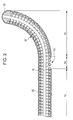
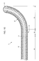
Fig. 2 is an enlarged view of a detailed structure of a distal end portion of the guidewire according to the first embodiment. -
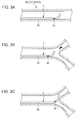
Figs. 3A to 3C are each an explanatory view of a state of operation using the guidewire according to the first embodiment. -
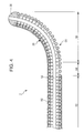
Fig. 4 is an enlarged view of a detailed structure of a distal end portion of a guidewire according to a second embodiment. -
Figs. 5A and 5B are each an explanatory view of a state of operation using the guidewire according to the second embodiment. -
Figs. 6A and 6B are each an explanatory view of a state of a different operation using the guidewire according to the second embodiment. -
Fig. 7 is an enlarged view of a detailed structure of a distal end portion of a guidewire according to a third embodiment. -
Figs. 8A and 8B are each an explanatory view of a state of operation using the guidewire according to the third embodiment. -
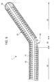
Fig. 9 is an enlarged view of a detailed structure of a distal end portion of a guidewire according to a fourth embodiment. -
Fig. 10 is an enlarged view of a detailed structure of a distal end portion of a guidewire according to a fifth embodiment. -
Figs. 11A and 11B are each an explanatory view of a structure of a guidewire according to a sixth embodiment. -
Figs. 12A and 12B are each an explanatory view of a state of operation using the guidewire according to the sixth embodiment. -
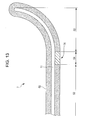
Fig. 13 is an explanatory view exemplifying a case in which the present invention is applied to a guidewire that does not include a coil body at its distal end side. -
Fig. 1 is a schematic explanatory view of a structure of aguidewire 1 according to a first embodiment. As shown inFig. 1 , theguidewire 1 according to the embodiment includes, for example, acore shaft 10 and acoil body 20 that is mounted to thecore shaft 10. - The
core shaft 10 includes aproximal end portion 12, adistal end portion 14 whose wire diameter is less than that of theproximal end portion 12, and a taperingportion 16 that connects theproximal end portion 12 and thedistal end portion 14 to each other. Thecoil body 20 is secured at a distal end side of thedistal end portion 14 by a distal-end-side brazingportion 30, and is secured to a proximal end side of thedistal end portion 14 by a proximal-end-side brazing portion 32. - The shape of the
core shaft 10 is not limited to the shape that is exemplified inFig. 1 . For example, thecore shaft 10 may have a shape in which the diameter of thedistal end portion 14 decreases from a proximal end to a distal end. Such a shape makes it possible to increase flexibility of a distal end portion of theguidewire 1. As a suitable material of thecore shaft 10, for example, stainless steel (SUS) or a superelastic alloy such as an Ni-Ti alloy, is used. - The
guidewire 1 according to the embodiment is gently bent from a position of the coil body 20 (that is, a position that is separated from a proximal-end side of a distal end of the coil body 20), so that a distal end of theguidewire 1 has a curved shape. In the description below, a portion having a curved shape at the distal end of the guidewire is called acurved portion 50, a portion of the guidewire that is closer to the proximal end side than thecurved portion 50 is called a linear portion 52 (the straight portion of the guidewire 1), and a boundary portion between thecurved portion 50 and thelinear portion 52 is called aboundary portion 54. -
Fig. 2 is an enlarged view of a detailed structure of the vicinity of the distal end of theguidewire 1 according to the first embodiment. As shown inFig. 2 , a surface of the guidewire 1 (more precisely, a surface of the coil body 20) is covered with alubricant portion 60 in the form of a thin layer. Materials that are more unlikely to generate friction with respect to an outside portion than the surface of the guidewire 1 (here, the surface of the coil body 20) are used. Examples of such materials are fluorocarbon resin, silicone oil, cellulose-based high polymer materials, polyethylene oxide based high polymer materials, maleic anhydride based high polymer materials (such as maleic anhydride copolymer including methyl vinyl ether-maleic anhydride copolymer), acrylamide based high polymer materials (such as polyacrylamide, polyglycidyl methacrylate-dimethylacrylamide block copolymer), watersoluble nylon, polyvinyl alcohol, polyvinyl pyrrolidone, and hyaluronate. Although, inFig. 2 , the state in which thelubricant portion 60 is provided at the surface of thecoil body 20 is exemplified, thelubricant portion 60 may also be provided at a surface of thecore shaft 10 that is closer to the proximal end than thecoil body 20. - In the
guidewire 1 according to the embodiment, a portion that is not covered by the lubricant portion 60 (that is, a low lubricant portion 62) is provided at a surface of theboundary portion 54 disposed at a side opposite to a side towards which thecurved portion 50 is curved. - The
low lubricant portion 62 is formed, for example, as follows. First, the surface of theguidewire 1 is covered with thelubricant portion 60. Then, a portion of thelubricant portion 60 that is provided at the surface of theboundary portion 54 disposed at the side opposite to the side towards which thecurved portion 50 is curved is removed to form thelow lubricant portion 62. This makes it possible to easily form thelow lubricant portion 62 by only removing a portion of thelubricant portion 60. -
Figs. 3A to 3C are each an explanatory view of a state of operation using theguidewire 1 according to the first embodiment.Fig. 3A shows a state in which theguidewire 1 is inserted in a blood vessel that is not branched.Figs. 3B and 3C each show a state in which theguidewire 1 is inserted in a portion where the blood vessel is branched. - As described above, a large portion of the surface of the
guidewire 1 according to the embodiment is covered by the lubricant portion 60 (seeFig. 2 ). Therefore, as shown inFig. 3A , when theguidewire 1 passes through a blood vessel, thelubricant portion 60 reduces friction between the surface of theguidewire 1 and an inside wall of the blood vessel. Consequently, theguidewire 1 can be smoothly moved into the blood vessel. - When the distal end of the
guidewire 1 reaches a branched portion of the blood vessel, an operator rotates theproximal end portion 12 of theguidewire 1 while gripping theproximal end portion 12 of theguidewire 1. When this is done, as shown inFig. 3B , the distal end of thecurved portion 50 of theguidewire 1 is oriented in the direction in which the operator tries to move theguidewire 1 forward (hereunder referred to as "forward direction"). - Here, in the
guidewire 1 according to the first embodiment, as described above, thelow lubricant portion 62 is provided at the surface of theboundary portion 54 disposed at the side opposite to the side towards which thecurved portion 50 is curved (seeFig. 2 ). Therefore, friction force between thelow lubricant portion 62 and the inside wall of the blood vessel allows the direction of theguidewire 1 to be stably maintained while the distal end of theguidewire 1 is oriented in the forward direction. Consequently, when theguidewire 1 that is in the state shown inFig. 3B is further pushed in from the proximal end side, as shown inFig. 3C , the operator can reliably insert theguidewire 1 into a selected blood vessel. - When the
low lubricant portion 62 is provided in the vicinity of the distal end of theguidewire 1 according to the first embodiment, thelow lubricant portion 62 receives resistance from the inside wall of the blood vessel (or a lesion), so that the operator can easily feel with his/her hand that the distal end of theguidewire 1 has contacted, for example, the inside wall of the blood vessel. Therefore, the operator can easily collect information regarding the vicinity of the distal end of the guidewire 1 (such as the shape of the blood vessel and the state of the legion) while the lubricating ability of the guidewire with respect to the inside wall of the blood vessel is provided by thelubricant portion 60. - The
guidewire 1 according to the first embodiment is described above. Other embodiments that are related thereto are hereunder simply described. In the description below, structural portions that correspond to those of the above-described first embodiment are given the same reference numerals as those in the first embodiment, and are not described in detail below. -
Fig. 4 is an enlarged view of a detailed structure of the vicinity of a distal end of aguidewire 2 according to a second embodiment. The illustratedguidewire 2 according to the second embodiment differs from theguidewire 1 according to the first embodiment in that the position where a low lubricant portion is provided (that is, a portion that is not covered by a lubricant portion 60) differs. That is, the low lubricant portion (low lubricant portion 64) is provided not only at a surface of aboundary portion 54 disposed at a side opposite to a side towards which acurved portion 50 of theguidewire 2 is curved, but also at a surface of thecurved portion 50 disposed at the side opposite to the side towards which thecurved portion 50 is curved. - In the second embodiment, the
lubricant portion 60 is not provided at a surface of a distal-end-side brazing portion 30 (that is, this surface of the distal-end-side brazing portion 30 is defined as the low lubricant portion 64). This suppresses penetration of the distal end of theguidewire 2 through a blood vessel when the lubricating ability of the distal end of theguidewire 2 is restricted. Obviously, when the lubricating ability of a surface of theguidewire 2 takes priority, thelubricant portion 60 may also be provided at the surface of the distal-end-side brazing portion 30 (this case is not shown). -
Figs. 5A and 5B are each an explanatory view of a state of operation using theguidewire 2 according to the second embodiment.Figs. 5A and 5B each show a state when theguidewire 2 is inserted into a portion of a blood vessel that is occluded (hereunder referred to as "occluded part") while the occluded part exists just in front of a branched portion of the blood vessel. - As shown in
Fig. 5A , when an attempt is made to insert theguidewire 2 into the occluded part, the distal end of theguidewire 2 receives an opposing force (indicated by a black arrow inFig. 5A ) from the occluded part. Here, in theguidewire 2 according to the second embodiment, the surface at the side opposite to the side towards which thecurved portion 50 is curved is also defined as thelow lubricant portion 64. Therefore, friction force is generated between thelow lubricant portion 64 and an inside wall of the blood vessel at an entrance portion of the occluded part (or the structure of the occluded part). Consequently, it is possible to suppress falling of theguidewire 2 into an illustrated lower blood vessel when theguidewire 2 is overcome by the opposing force of the occluded part. As a result, as shown inFig. 5B , it is possible to reliably insert theguidewire 2 into the occluded part. In addition, since thelubricant portion 60 is provided at the surface of theguidewire 2 disposed at the side towards which thecurved portion 50 is curved, it is possible to smoothly move theguidewire 2 into the occluded part. -
Figs. 6A and 6B are each an explanatory view of a state of a different operation using theguidewire 2 according to the second embodiment.Figs. 6A and 6B each show a state in which theguidewire 2 is inserted into an occluded part when a blood vessel substantially perpendicularly branches off from a linear blood vessel and an occluded part exists right in front of the branched-off portion. - As shown in
Fig. 6A , when the distal end of theguidewire 2 is inserted into an entrance portion of the occluded part, friction is generated between thelow lubricant portion 64 and the structure of the occluded part, as a result of which the distal end portion of theguidewire 2 is caught by the entrance portion of the occluded part. In this state, when theguidewire 2 is pushed in from a proximal-end side (illustrated left side), sliding of the distal end of theguidewire 2 in a push-in direction (illustrated right direction) is suppressed. As a result, as shown inFig. 6B , even if the occluded part exists at the entrance portion of the blood vessel that branches off substantially perpendicularly, it is possible to reliably insert theguidewire 2 into the occluded part. -
Fig. 7 is an enlarged view of a detailed structure of the vicinity of a distal end of aguidewire 3 according to a third embodiment. The illustratedguidewire 3 according to the third embodiment differs from the above-describedguidewire 2 according to the second embodiment in that alow lubricant portion 66 is provided not only at a surface of aboundary portion 54 and a surface of acurved portion 50 disposed at a side opposite to a side towards which thecurved portion 50 is curved, but also at a surface of theboundary portion 54 and a surface of thecurved portion 50 disposed at the side towards which thecurved portion 50 is curved. - In such a
guidewire 3 according to the third embodiment, the area of thelubricant portion 66 at the distal end of theguidewire 3 is greater than the areas of the lubricant portions in the guidewires according to the first and second embodiments. As a result, when the distal end of theguidewire 3 contacts, for example, an inside wall of a blood vessel or an occluded part, an operator (proximal-end side) can more reliably feel with his/her hand that the distal end of theguidewire 3 has contacted, for example, an inside wall of a blood vessel or an occluded part. Therefore, theguidewire 3 according to the third embodiment can be suitably used when performing an operation (such as an operation of passing theguidewire 3 through the occluded part or an operation of inserting theguidewire 3 into a very fine blood vessel) requiring the operator to precisely feel with his/her hand that the distal end of theguidewire 3 has contacted, for example, an inside wall of a blood vessel or an occluded part. - The
guidewire 3 according to the third embodiment may be suitably used in the following operations. -
Figs. 8A and 8B are each an explanatory view of a state of operation using theguidewire 3 according to the third embodiment. As shown inFig. 8A , when theguidewire 3 is rotated at the proximal-end side while the distal end of theguidewire 3 is inserted in an occluded part of a blood vessel, the orientation of the distal end of theguidewire 3 changes. Here, when the entire surface of the guidewire is covered by alubricant portion 60 as in existing guidewires, the surface of the guidewire slides excessively with respect to the occluded part, as a result of which the distal end of the guidewire may rotate excessively by an amount that is greater than that expected by an operator. In contrast, when the entire surface of theboundary portion 54 and the entire surface of thecurved portion 50 are covered by thelow lubricant portion 66 as in theguidewire 3 according to the third embodiment, friction force is sufficiently provided at the distal-end portion of theguidewire 3, so that it is possible to suppress the aforementioned excessive rotation. As a result, it is possible to easily orient the distal end of theguidewire 3 in the occluded part. -
Fig. 9 is an enlarged view of a detailed structure of the vicinity of a distal end of a guidewire 4 according to a fourth embodiment. The illustrated guidewire 4 according to the fourth embodiment differs from the above-described guidewires according to the first to third embodiments in the way a distal end of the guidewire 4 is bent. That is, although each of the guidewires according to the first to third embodiments is such that its distal end is gently curved with theboundary portion 54 serving as a starting point, the guidewire 4 according to the fourth embodiment is such that its distal end is bent at a position that is separated from its distal end. In the description below, a portion where the guidewire 4 is bent is called abent portion 80, a linear portion that is closer to a proximal end than thebent portion 80 is called a firstlinear portion 82, and a linear portion that is closer to a distal end than thebent portion 80 is called a secondlinear portion 84. In the guidewire 4 according to the fourth embodiment, a bent portion only needs to be provided between the two linear portions (that is, the firstlinear portion 82 and the second linear portion 84). Therefore, thebent portion 80 need not be bent at a steep angle as it is inFig. 9 . Thebent portion 80 may be gently curved. - A
low lubricant portion 68 is provided at a surface of thebent portion 80 disposed at a side opposite to a side towards which the guidewire 4 is bent. - Even here, as with the guidewires according to the first to third embodiments, it is possible to stably maintain the direction of the distal end of the guidewire 4 by friction force that is generated between the
low lubricant portion 68 and an inside wall of a blood vessel. In addition, when this portion is provided with thelow lubricant portion 68, it is possible for a side of thelow lubricant portion 68 to be an outwardly protruding side. Therefore, it is possible to reliably contact thelow lubricant portion 68 and the inside wall of the blood vessel, as a result of which it is possible to more easily orient the distal end of the guidewire 4. Further, in the guidewire 4 according to the fourth embodiment, by bending thecoil body 20 at thebent portion 80, it is possible for the pitch in thecoil body 20 at thelow lubricant portion 68 to be greater than the pitches in thecoil bodies 20 at thelow lubricant portions 68 of the guidewires according to the above-described first to third embodiments. Accordingly, since the surface of the guidewire 4 at thelow lubricant portion 68 is very rough, it is possible to provide sufficient friction force between thelow lubricant portion 68 and the inside wall of the blood vessel. -
Fig. 9 exemplifies a case in which, in the guidewire 4 having a bent distal end portion, thelow lubricant portion 68 is provided at the surface of thebent portion 80 disposed at the side opposite to the side towards which the guidewire 4 is bent. As in the case described above with reference toFig. 4 , thelow lubricant portion 68 may be provided at the surface of the secondlinear portion 84 and at the surface of thebent portion 80 disposed at the side opposite to the side towards which the guidewire 4 is bent (this case is not shown). This makes it possible to achieve the advantageous effects of both the second embodiment and the fourth embodiment. In addition, as in the case described above with reference toFig. 7 , thelow lubricant portion 68 may be provided not only at the surface of the secondlinear portion 84 and the surface of thebent portion 80 disposed at the side opposite to the side towards which the guidewire 4 is bent, but also at a surface of the secondlinear portion 84 and a surface of thebent portion 80 disposed at the side towards which theguidewire 3 is bent (this case is not shown). This makes it possible to achieve the advantageous effects of both the third embodiment and the fourth embodiment. -
Fig. 10 is an enlarged view of a detailed structure of the vicinity of a distal end of a guidewire 5 according to a fifth embodiment. The illustrated guidewire 5 according to the fifth embodiment differs from the other guidewires according to the first to fourth embodiments in the method of forming a low lubricant portion. That is, although, in each of the above-described guidewires according to the first to fourth embodiments, the low lubricant portion is formed by removing a portion of thelubricant portion 60, in the fifth embodiment, a portion of the guidewire 5 where thelubricant portion 60 has been removed is covered with a material (such as a resin material) having a lubricating ability that is lower than that of thelubricant portion 60, so that alow lubricant portion 70 is formed. -
Fig. 10 exemplifies a form in which theguidewire 1 according to the first embodiment shown inFig. 2 is provided with a covering having low lubricating ability at a portion thereof where a portion of thelubricant portion 60 has been removed. However, the fifth embodiment is not limited to the form exemplified inFig. 10 . The guidewire 5 according to the fifth embodiment may have, for example, a form in which theguidewire 2 according to the second embodiment shown inFig. 4 is covered with thelow lubricant portion 70 at a portion thereof where thelubricant portion 60 has been removed, a form in which theguidewire 3 according to the third embodiment shown inFig. 7 is covered with thelow lubricant portion 70 at a portion thereof where thelubricant portion 60 has been removed, or a form in which the guidewire 4 according to the fourth embodiment shown inFig. 9 is covered with thelow lubricant portion 70 at a portion thereof where thelubricant portion 60 has been removed. - Even in these cases, as with the guidewires according to the above-described first to fourth embodiments, it is possible to stably maintain the direction of the distal end of the guidewire 5 by friction force that is generated between the
low lubricant portion 70 and an inside wall of a blood vessel. In addition, when thelow lubricant portion 70 is provided in this way, it is possible to change the friction force at thelow lubricant portion 70 by the type of material used for thelow lubricant portion 70. As a result, it is possible to set the friction force at thelow lubricant portion 70 to a desired value without being influenced by the friction force at the surface of the guidewire 5 (here, the surface of the coil body 20). -
-
Figs. 11A and 11B are each an explanatory view of a structure of aguidewire 6 according to a sixth embodiment.Fig. 11A shows a general structure of theguidewire 6 according to the sixth embodiment.Fig. 11B shows a detailed structure of the vicinity of a distal end of theguidewire 6 according to the sixth embodiment. - As shown in
Fig. 11A , theguidewire 6 according to the sixth embodiment differs from the guide wires according to the above-described first to fifth embodiments in that a coil body structure that is provided at adistal end portion 14 of acore shaft 10 has a double structure. In the description below, a coil body at the outer side is called anouter coil body 22, and a coil body at the inner side is called aninner coil body 24. Theinner coil body 24 is secured to a distal end side of thedistal end portion 14 by a distal-end-side brazing portion 30, and is secured inwardly of thedistal end portion 14 by anintermediate brazing portion 34. - The
inner coil body 24 is, for example, a circular cylindrical body in which a single strand is spirally wound or a circular cylindrical body in which a plurality of strands are twisted together. Theinner coil body 24 may be flexible or elastic. - The
guidewire 6 according to the sixth embodiment is assembled as follows. First, the linearouter coil body 22, alinear core shaft 10, and the curvedinner coil body 24 are provided. Then, the distal end of thecore shaft 10 is inserted into and mounted to the curvedinner coil body 24. Lastly, the distal end of thecore shaft 10 to which theinner coil body 24 is mounted is inserted into and mounted to the linearouter coil body 22. As shown inFig. 11B , theguidewire 6 that has been assembled in this way is formed such that the curvature of theinner coil body 24 is greater than the curvature of theouter coil body 22. This means that theouter coil body 22 is curved by a force (restoring force) that causes theinner coil body 24 to be restored to its original shape, as a result of which, as shown inFig. 11B , the shape (curved shape) of the distal end of theguidewire 6 is maintained. - In this way, the restoring force of the
inner coil body 24 acts upon theouter coil body 22 of theguidewire 6 according to the sixth embodiment at all times. Therefore, compared to guidewires formed into a similar shape by merely causing the distal end of thecoil body 20 to be curved, theguidewire 6 is easily bent in the direction in which theguidewire 6 is curved when theguidewire 6 receives resistance from the distal end side of theguidewire 6. - In addition, as with the above-described
guidewire 2 according to the second embodiment, theguidewire 6 includes alubricant portion 60, provided at a surface of theouter coil body 22, and alow lubricant portion 72, provided a surface of acurved portion 50 and a surface of aboundary portion 54 disposed at a side opposite to a side towards which thecurved portion 50 is curved. -
Figs. 12A and 12B are each an explanatory view of a state of operation using theguidewire 6 according to the sixth embodiment. As described above, as with theguidewire 2 according to the second embodiment, theguidewire 6 according to the sixth embodiment includes thelow lubricant portion 72. Therefore, it is possible to achieve the same advantageous effects as those of theguidewire 2 according to the second embodiment. That is, as shown inFig. 12A , even if theguidewire 6 receives an opposing force from an occluded part, friction force that acts between thelow lubricant portion 72 and an inside wall of a blood vessel (or the structure of the occluded part) allows theguidewire 6 to be reliably inserted into the occluded part. - Since the
guidewire 6 according to the sixth embodiment has the above-described structure (seeFigs. 11A and 11B ), when theguidewire 6 receives resistance from its distal end side, theguidewire 6 is easily bent in the direction in which theguidewire 6 is curved. Therefore, when theguidewire 6 is further pushed in from the state shown inFig. 12A , the resistance from the occluded part causes the distal end of theguidewire 6 to be bent in the direction in which theguidewire 6 is curved. - In this way, the distal end of the
guidewire 6 can be oriented in the direction of a center axis of a blood vessel from a wall side of the blood vessel at the occluded part. Therefore, when inserting theguidewire 6 into the occluded part, it is possible to suppress rubbing between thelow lubricant portion 72 and the inside wall of the blood vessel at the occluded part. As a result, it is possible to more smoothly insert theguidewire 6 into the occluded part. - Although various embodiments have been described, the present invention is not limited to the above-described embodiments, so that the present invention may be carried out in various forms within a scope that does not depart from the gist of the present invention. For example, the above-described guidewires according to the embodiments are described as including a
coil body 20 at thedistal end portion 14 of thecore shaft 10. However, the guidewires need not include acoil body 20. Similar advantageous effects may be achieved even if the present invention is applied to a guidewire that does not include acoil body 20.Fig. 13 exemplifies a case in which a surface of acore shaft 11 is provided with alubricant portion 60 and in which, in a guidewire 7 whose distal end has a curved shape, a low lubricant portion 74 is provided at aboundary portion 54 disposed at a side opposite to a side towards which acurved portion 50 is curved. Obviously, as with, for example, the above-described embodiments, when the present invention is applied to theguidewire 1 including acoil body 20 at thedistal end portion 14 of thecore shaft 10, the roughness of the surface of thecoil body 20 makes it possible to provide sufficient friction force. Therefore, from the viewpoint of reliably orienting the distal end of thecurved portion 50, it is more desirable than the above-described embodiments.
Claims (7)
- A guidewire (1, 2, 3, 4, 5, 7) comprising:a linear portion (52);a curved portion (50) that is provided at a distal end side of the linear portion (52);a boundary portion (54) that is provided between the linear portion (52) and the curved portion (50);a lubricant portion (60) that is provided at a surface of the linear portion (52); anda low lubricant portion (62, 64, 66, 68, 70, 72, 74) that is provided at least at a surface of the boundary portion (54) disposed at a side opposite to a side towards which the curved portion (50) is curved, a lubricating ability of the low lubricant portion (62, 64, 66, 68, 70, 72, 74) being lower than that of the lubricant portion (60).
- The guidewire according to Claim 1, wherein the low lubricant portion is provided to a distal end of the curved portion from the boundary portion disposed at the side opposite to the side towards which the curved portion is curved.
- The guidewire according to Claim 2, wherein the low lubricant portion is also provided to the distal end of the curved portion from the boundary portion disposed at the side towards which the curved portion is curved.
- A guidewire comprising:a first linear portion (82);a second linear portion (84) that is provided at a distal end side of the first linear portion (82);a bent portion (80) that is provided between the first linear portion (82) and the second linear portion (84);a lubricant portion (60) that is provided at a surface of the first linear portion (82); anda low lubricant portion that is provided at least at a surface of the bent portion (80) disposed at a side opposite to a side towards which the bent portion (80) is bent, a lubricating ability of the low lubricant portion being lower than that of the lubricant portion.
- The guidewire according to Claim 4, wherein the low lubricant portion is provided to a distal end of the second linear portion from the bent portion disposed at the side opposite to the side towards which the bent portion is bent.
- The guidewire according to Claim 5, wherein the low lubricant portion is also provided to the distal end of the second linear portion from the bent portion disposed at the side towards which the bent portion is bent.
- The guidewire according to any one of Claims 1 to 6, wherein the low lubricant portion is formed by removing a portion of the lubricant portion that is provided at a surface of the guidewire.
Applications Claiming Priority (1)
| Application Number | Priority Date | Filing Date | Title |
|---|---|---|---|
| JP2012284224A JP5780526B2 (en) | 2012-12-27 | 2012-12-27 | Guide wire |
Publications (2)
| Publication Number | Publication Date |
|---|---|
| EP2749314A1 true EP2749314A1 (en) | 2014-07-02 |
| EP2749314B1 EP2749314B1 (en) | 2016-03-30 |
Family
ID=49378033
Family Applications (1)
| Application Number | Title | Priority Date | Filing Date |
|---|---|---|---|
| EP13186571.9A Not-in-force EP2749314B1 (en) | 2012-12-27 | 2013-09-30 | Guidewire |
Country Status (4)
| Country | Link |
|---|---|
| US (1) | US9295813B2 (en) |
| EP (1) | EP2749314B1 (en) |
| JP (1) | JP5780526B2 (en) |
| CN (1) | CN103893899B (en) |
Families Citing this family (15)
| Publication number | Priority date | Publication date | Assignee | Title |
|---|---|---|---|---|
| CA3012709C (en) | 2016-03-18 | 2022-07-12 | Teleflex Innovations S.A.R.L. | Pacing guidewire |
| WO2018062155A1 (en) * | 2016-09-30 | 2018-04-05 | テルモ株式会社 | Guide wire |
| US10085766B1 (en) | 2017-03-31 | 2018-10-02 | Jihad A. Mustapha | Chronic total occlusion crossing devices and methods |
| JP2018187229A (en) | 2017-05-10 | 2018-11-29 | テルモ株式会社 | Medical long body |
| WO2019064607A1 (en) * | 2017-09-30 | 2019-04-04 | 朝日インテック株式会社 | Guide wire |
| CN109758661B (en) * | 2018-08-24 | 2021-11-23 | 中国医学科学院阜外医院 | Preformed guide wire for treating bifurcation lesion in blood vessel |
| US11452533B2 (en) * | 2019-01-10 | 2022-09-27 | Abbott Cardiovascular Systems Inc. | Guide wire tip having roughened surface |
| JP7261879B2 (en) * | 2019-06-28 | 2023-04-20 | 朝日インテック株式会社 | guide wire |
| WO2021044923A1 (en) * | 2019-09-02 | 2021-03-11 | テルモ株式会社 | Catheter |
| US11904117B2 (en) | 2019-10-31 | 2024-02-20 | Abbott Cardiovascular Systems Inc. | Guidewire having radiopaque inner coil |
| US11285299B2 (en) | 2019-10-31 | 2022-03-29 | Abbott Cardiovascular Systems Inc. | Mold for forming solder distal tip for guidewire |
| US12539395B2 (en) | 2019-10-31 | 2026-02-03 | Abbott Cardiovascular Systems Inc. | Guidewire tip shaping tool |
| US11911051B2 (en) | 2019-10-31 | 2024-02-27 | Abbott Cardiovascular Systems Inc. | Dimpled joint for guidewire |
| US11684759B2 (en) | 2020-01-22 | 2023-06-27 | Abbott Cardiovascular Systems Inc. | Guidewire having varying diameters and method of making |
| JP2021186076A (en) * | 2020-05-27 | 2021-12-13 | 朝日インテック株式会社 | Medical device |
Citations (4)
| Publication number | Priority date | Publication date | Assignee | Title |
|---|---|---|---|---|
| JPH09294813A (en) | 1995-12-07 | 1997-11-18 | Sarcos Inc | Catheter guide wire |
| US20040167438A1 (en) * | 2003-02-26 | 2004-08-26 | Sharrow James S. | Reinforced medical device |
| JP2008237621A (en) | 2007-03-27 | 2008-10-09 | Japan Lifeline Co Ltd | Medical insertion device and method for manufacturing the same |
| WO2009146339A1 (en) * | 2008-05-30 | 2009-12-03 | Boston Scientific Scimed, Inc. | Medical device including a polymer sleeve and a coil wound into the polymer sleeve |
Family Cites Families (16)
| Publication number | Priority date | Publication date | Assignee | Title |
|---|---|---|---|---|
| US4763647A (en) * | 1987-01-06 | 1988-08-16 | C. R. Bard, Inc. | Dual coil steerable guidewire |
| US4886067A (en) * | 1989-01-03 | 1989-12-12 | C. R. Bard, Inc. | Steerable guidewire with soft adjustable tip |
| US5772609A (en) * | 1993-05-11 | 1998-06-30 | Target Therapeutics, Inc. | Guidewire with variable flexibility due to polymeric coatings |
| US5833632A (en) | 1995-12-07 | 1998-11-10 | Sarcos, Inc. | Hollow guide wire apparatus catheters |
| JPH1071209A (en) * | 1996-08-29 | 1998-03-17 | Asahi Intec Kk | Guide wire |
| US6251086B1 (en) * | 1999-07-27 | 2001-06-26 | Scimed Life Systems, Inc. | Guide wire with hydrophilically coated tip |
| JP4409726B2 (en) | 2000-07-05 | 2010-02-03 | テルモ株式会社 | Guide wire |
| US7001345B2 (en) * | 2002-08-23 | 2006-02-21 | Cook Incorporated | Wire guide |
| US20040102719A1 (en) * | 2002-11-22 | 2004-05-27 | Velocimed, L.L.C. | Guide wire control catheters for crossing occlusions and related methods of use |
| US7687144B2 (en) | 2003-02-20 | 2010-03-30 | Wilson-Cook Medical, Inc. | Medical device with adherent coating, and method for preparing same |
| DE602004018331D1 (en) * | 2003-09-05 | 2009-01-22 | Cook Urological Inc | GUIDE WIRE WITH DOUBLE END |
| US20050096665A1 (en) * | 2003-10-30 | 2005-05-05 | Scimed Life Systems, Inc. | Guidewire having a helically contoured portion |
| JP4405252B2 (en) * | 2003-12-24 | 2010-01-27 | テルモ株式会社 | Medical wire |
| JP4896245B2 (en) * | 2010-03-31 | 2012-03-14 | 朝日インテック株式会社 | Guide wire |
| JP5690631B2 (en) * | 2011-03-30 | 2015-03-25 | 日本コヴィディエン株式会社 | Lubricating medical device and method for manufacturing the same |
| JP5424499B2 (en) * | 2011-04-18 | 2014-02-26 | 朝日インテック株式会社 | Medical guidewire |
-
2012
- 2012-12-27 JP JP2012284224A patent/JP5780526B2/en not_active Expired - Fee Related
-
2013
- 2013-09-06 CN CN201310401788.2A patent/CN103893899B/en not_active Expired - Fee Related
- 2013-09-30 EP EP13186571.9A patent/EP2749314B1/en not_active Not-in-force
- 2013-10-02 US US14/044,414 patent/US9295813B2/en not_active Expired - Fee Related
Patent Citations (4)
| Publication number | Priority date | Publication date | Assignee | Title |
|---|---|---|---|---|
| JPH09294813A (en) | 1995-12-07 | 1997-11-18 | Sarcos Inc | Catheter guide wire |
| US20040167438A1 (en) * | 2003-02-26 | 2004-08-26 | Sharrow James S. | Reinforced medical device |
| JP2008237621A (en) | 2007-03-27 | 2008-10-09 | Japan Lifeline Co Ltd | Medical insertion device and method for manufacturing the same |
| WO2009146339A1 (en) * | 2008-05-30 | 2009-12-03 | Boston Scientific Scimed, Inc. | Medical device including a polymer sleeve and a coil wound into the polymer sleeve |
Also Published As
| Publication number | Publication date |
|---|---|
| CN103893899A (en) | 2014-07-02 |
| US9295813B2 (en) | 2016-03-29 |
| CN103893899B (en) | 2016-05-11 |
| JP5780526B2 (en) | 2015-09-16 |
| US20140188004A1 (en) | 2014-07-03 |
| EP2749314B1 (en) | 2016-03-30 |
| JP2014124408A (en) | 2014-07-07 |
Similar Documents
| Publication | Publication Date | Title |
|---|---|---|
| US9295813B2 (en) | Guidewire | |
| US8043232B2 (en) | High performance wire guide | |
| JP4907945B2 (en) | Medical guidewire | |
| US8608670B2 (en) | Guidewire | |
| KR20120027116A (en) | Medical guide wire | |
| EP2338555A2 (en) | Guidewire | |
| EP2502645A1 (en) | Guidewire | |
| US9492642B2 (en) | Guidewire | |
| JPWO2007105531A1 (en) | Guide wire | |
| CN106456942B (en) | Kink-resistant guidewire with improved stiffness | |
| EP2481441A1 (en) | Guidewire | |
| JPWO2011081134A1 (en) | Guide wire | |
| JP2013039305A (en) | Guidewire | |
| JP2012200290A (en) | Guidewire | |
| WO2022158418A1 (en) | Catheter | |
| JP5280263B2 (en) | Guide wire | |
| JP3179894U (en) | catheter | |
| JP5376531B2 (en) | Guide wire | |
| JP7689449B2 (en) | Guidewires | |
| JP7474775B2 (en) | Guidewires | |
| JP5580802B2 (en) | Medical guidewire | |
| JP4316252B2 (en) | catheter | |
| WO2024106172A1 (en) | Guide wire | |
| WO2024024349A1 (en) | Dilator | |
| JP2024040728A (en) | catheter |
Legal Events
| Date | Code | Title | Description |
|---|---|---|---|
| 17P | Request for examination filed |
Effective date: 20130930 |
|
| AK | Designated contracting states |
Kind code of ref document: A1 Designated state(s): AL AT BE BG CH CY CZ DE DK EE ES FI FR GB GR HR HU IE IS IT LI LT LU LV MC MK MT NL NO PL PT RO RS SE SI SK SM TR |
|
| AX | Request for extension of the european patent |
Extension state: BA ME |
|
| PUAI | Public reference made under article 153(3) epc to a published international application that has entered the european phase |
Free format text: ORIGINAL CODE: 0009012 |
|
| R17P | Request for examination filed (corrected) |
Effective date: 20140625 |
|
| RBV | Designated contracting states (corrected) |
Designated state(s): AL AT BE BG CH CY CZ DE DK EE ES FI FR GB GR HR HU IE IS IT LI LT LU LV MC MK MT NL NO PL PT RO RS SE SI SK SM TR |
|
| GRAP | Despatch of communication of intention to grant a patent |
Free format text: ORIGINAL CODE: EPIDOSNIGR1 |
|
| INTG | Intention to grant announced |
Effective date: 20150918 |
|
| GRAS | Grant fee paid |
Free format text: ORIGINAL CODE: EPIDOSNIGR3 |
|
| GRAA | (expected) grant |
Free format text: ORIGINAL CODE: 0009210 |
|
| AK | Designated contracting states |
Kind code of ref document: B1 Designated state(s): AL AT BE BG CH CY CZ DE DK EE ES FI FR GB GR HR HU IE IS IT LI LT LU LV MC MK MT NL NO PL PT RO RS SE SI SK SM TR |
|
| REG | Reference to a national code |
Ref country code: GB Ref legal event code: FG4D |
|
| REG | Reference to a national code |
Ref country code: CH Ref legal event code: EP |
|
| REG | Reference to a national code |
Ref country code: AT Ref legal event code: REF Ref document number: 784689 Country of ref document: AT Kind code of ref document: T Effective date: 20160415 |
|
| REG | Reference to a national code |
Ref country code: IE Ref legal event code: FG4D |
|
| REG | Reference to a national code |
Ref country code: DE Ref legal event code: R096 Ref document number: 602013005874 Country of ref document: DE |
|
| REG | Reference to a national code |
Ref country code: LT Ref legal event code: MG4D |
|
| PG25 | Lapsed in a contracting state [announced via postgrant information from national office to epo] |
Ref country code: GR Free format text: LAPSE BECAUSE OF FAILURE TO SUBMIT A TRANSLATION OF THE DESCRIPTION OR TO PAY THE FEE WITHIN THE PRESCRIBED TIME-LIMIT Effective date: 20160701 Ref country code: NO Free format text: LAPSE BECAUSE OF FAILURE TO SUBMIT A TRANSLATION OF THE DESCRIPTION OR TO PAY THE FEE WITHIN THE PRESCRIBED TIME-LIMIT Effective date: 20160630 Ref country code: FI Free format text: LAPSE BECAUSE OF FAILURE TO SUBMIT A TRANSLATION OF THE DESCRIPTION OR TO PAY THE FEE WITHIN THE PRESCRIBED TIME-LIMIT Effective date: 20160330 Ref country code: HR Free format text: LAPSE BECAUSE OF FAILURE TO SUBMIT A TRANSLATION OF THE DESCRIPTION OR TO PAY THE FEE WITHIN THE PRESCRIBED TIME-LIMIT Effective date: 20160330 |
|
| REG | Reference to a national code |
Ref country code: NL Ref legal event code: MP Effective date: 20160330 |
|
| REG | Reference to a national code |
Ref country code: AT Ref legal event code: MK05 Ref document number: 784689 Country of ref document: AT Kind code of ref document: T Effective date: 20160330 |
|
| PG25 | Lapsed in a contracting state [announced via postgrant information from national office to epo] |
Ref country code: RS Free format text: LAPSE BECAUSE OF FAILURE TO SUBMIT A TRANSLATION OF THE DESCRIPTION OR TO PAY THE FEE WITHIN THE PRESCRIBED TIME-LIMIT Effective date: 20160330 Ref country code: SE Free format text: LAPSE BECAUSE OF FAILURE TO SUBMIT A TRANSLATION OF THE DESCRIPTION OR TO PAY THE FEE WITHIN THE PRESCRIBED TIME-LIMIT Effective date: 20160330 Ref country code: LV Free format text: LAPSE BECAUSE OF FAILURE TO SUBMIT A TRANSLATION OF THE DESCRIPTION OR TO PAY THE FEE WITHIN THE PRESCRIBED TIME-LIMIT Effective date: 20160330 Ref country code: LT Free format text: LAPSE BECAUSE OF FAILURE TO SUBMIT A TRANSLATION OF THE DESCRIPTION OR TO PAY THE FEE WITHIN THE PRESCRIBED TIME-LIMIT Effective date: 20160330 |
|
| PG25 | Lapsed in a contracting state [announced via postgrant information from national office to epo] |
Ref country code: NL Free format text: LAPSE BECAUSE OF FAILURE TO SUBMIT A TRANSLATION OF THE DESCRIPTION OR TO PAY THE FEE WITHIN THE PRESCRIBED TIME-LIMIT Effective date: 20160330 |
|
| PG25 | Lapsed in a contracting state [announced via postgrant information from national office to epo] |
Ref country code: IS Free format text: LAPSE BECAUSE OF FAILURE TO SUBMIT A TRANSLATION OF THE DESCRIPTION OR TO PAY THE FEE WITHIN THE PRESCRIBED TIME-LIMIT Effective date: 20160730 Ref country code: EE Free format text: LAPSE BECAUSE OF FAILURE TO SUBMIT A TRANSLATION OF THE DESCRIPTION OR TO PAY THE FEE WITHIN THE PRESCRIBED TIME-LIMIT Effective date: 20160330 Ref country code: PL Free format text: LAPSE BECAUSE OF FAILURE TO SUBMIT A TRANSLATION OF THE DESCRIPTION OR TO PAY THE FEE WITHIN THE PRESCRIBED TIME-LIMIT Effective date: 20160330 |
|
| PG25 | Lapsed in a contracting state [announced via postgrant information from national office to epo] |
Ref country code: AT Free format text: LAPSE BECAUSE OF FAILURE TO SUBMIT A TRANSLATION OF THE DESCRIPTION OR TO PAY THE FEE WITHIN THE PRESCRIBED TIME-LIMIT Effective date: 20160330 Ref country code: SK Free format text: LAPSE BECAUSE OF FAILURE TO SUBMIT A TRANSLATION OF THE DESCRIPTION OR TO PAY THE FEE WITHIN THE PRESCRIBED TIME-LIMIT Effective date: 20160330 Ref country code: CZ Free format text: LAPSE BECAUSE OF FAILURE TO SUBMIT A TRANSLATION OF THE DESCRIPTION OR TO PAY THE FEE WITHIN THE PRESCRIBED TIME-LIMIT Effective date: 20160330 Ref country code: ES Free format text: LAPSE BECAUSE OF FAILURE TO SUBMIT A TRANSLATION OF THE DESCRIPTION OR TO PAY THE FEE WITHIN THE PRESCRIBED TIME-LIMIT Effective date: 20160330 Ref country code: SM Free format text: LAPSE BECAUSE OF FAILURE TO SUBMIT A TRANSLATION OF THE DESCRIPTION OR TO PAY THE FEE WITHIN THE PRESCRIBED TIME-LIMIT Effective date: 20160330 Ref country code: PT Free format text: LAPSE BECAUSE OF FAILURE TO SUBMIT A TRANSLATION OF THE DESCRIPTION OR TO PAY THE FEE WITHIN THE PRESCRIBED TIME-LIMIT Effective date: 20160801 Ref country code: RO Free format text: LAPSE BECAUSE OF FAILURE TO SUBMIT A TRANSLATION OF THE DESCRIPTION OR TO PAY THE FEE WITHIN THE PRESCRIBED TIME-LIMIT Effective date: 20160330 |
|
| PG25 | Lapsed in a contracting state [announced via postgrant information from national office to epo] |
Ref country code: BE Free format text: LAPSE BECAUSE OF FAILURE TO SUBMIT A TRANSLATION OF THE DESCRIPTION OR TO PAY THE FEE WITHIN THE PRESCRIBED TIME-LIMIT Effective date: 20160330 Ref country code: IT Free format text: LAPSE BECAUSE OF FAILURE TO SUBMIT A TRANSLATION OF THE DESCRIPTION OR TO PAY THE FEE WITHIN THE PRESCRIBED TIME-LIMIT Effective date: 20160330 |
|
| REG | Reference to a national code |
Ref country code: DE Ref legal event code: R097 Ref document number: 602013005874 Country of ref document: DE |
|
| PG25 | Lapsed in a contracting state [announced via postgrant information from national office to epo] |
Ref country code: DK Free format text: LAPSE BECAUSE OF FAILURE TO SUBMIT A TRANSLATION OF THE DESCRIPTION OR TO PAY THE FEE WITHIN THE PRESCRIBED TIME-LIMIT Effective date: 20160330 |
|
| PLBE | No opposition filed within time limit |
Free format text: ORIGINAL CODE: 0009261 |
|
| STAA | Information on the status of an ep patent application or granted ep patent |
Free format text: STATUS: NO OPPOSITION FILED WITHIN TIME LIMIT |
|
| 26N | No opposition filed |
Effective date: 20170103 |
|
| PG25 | Lapsed in a contracting state [announced via postgrant information from national office to epo] |
Ref country code: MC Free format text: LAPSE BECAUSE OF FAILURE TO SUBMIT A TRANSLATION OF THE DESCRIPTION OR TO PAY THE FEE WITHIN THE PRESCRIBED TIME-LIMIT Effective date: 20160330 |
|
| REG | Reference to a national code |
Ref country code: CH Ref legal event code: PL |
|
| PG25 | Lapsed in a contracting state [announced via postgrant information from national office to epo] |
Ref country code: SI Free format text: LAPSE BECAUSE OF FAILURE TO SUBMIT A TRANSLATION OF THE DESCRIPTION OR TO PAY THE FEE WITHIN THE PRESCRIBED TIME-LIMIT Effective date: 20160330 |
|
| REG | Reference to a national code |
Ref country code: IE Ref legal event code: MM4A |
|
| REG | Reference to a national code |
Ref country code: FR Ref legal event code: ST Effective date: 20170531 |
|
| PG25 | Lapsed in a contracting state [announced via postgrant information from national office to epo] |
Ref country code: FR Free format text: LAPSE BECAUSE OF NON-PAYMENT OF DUE FEES Effective date: 20160930 Ref country code: IE Free format text: LAPSE BECAUSE OF NON-PAYMENT OF DUE FEES Effective date: 20160930 Ref country code: LI Free format text: LAPSE BECAUSE OF NON-PAYMENT OF DUE FEES Effective date: 20160930 Ref country code: CH Free format text: LAPSE BECAUSE OF NON-PAYMENT OF DUE FEES Effective date: 20160930 |
|
| PG25 | Lapsed in a contracting state [announced via postgrant information from national office to epo] |
Ref country code: LU Free format text: LAPSE BECAUSE OF NON-PAYMENT OF DUE FEES Effective date: 20160930 |
|
| PG25 | Lapsed in a contracting state [announced via postgrant information from national office to epo] |
Ref country code: CY Free format text: LAPSE BECAUSE OF FAILURE TO SUBMIT A TRANSLATION OF THE DESCRIPTION OR TO PAY THE FEE WITHIN THE PRESCRIBED TIME-LIMIT Effective date: 20160330 Ref country code: HU Free format text: LAPSE BECAUSE OF FAILURE TO SUBMIT A TRANSLATION OF THE DESCRIPTION OR TO PAY THE FEE WITHIN THE PRESCRIBED TIME-LIMIT; INVALID AB INITIO Effective date: 20130930 |
|
| PG25 | Lapsed in a contracting state [announced via postgrant information from national office to epo] |
Ref country code: MT Free format text: LAPSE BECAUSE OF NON-PAYMENT OF DUE FEES Effective date: 20160930 Ref country code: MK Free format text: LAPSE BECAUSE OF FAILURE TO SUBMIT A TRANSLATION OF THE DESCRIPTION OR TO PAY THE FEE WITHIN THE PRESCRIBED TIME-LIMIT Effective date: 20160330 |
|
| PG25 | Lapsed in a contracting state [announced via postgrant information from national office to epo] |
Ref country code: BG Free format text: LAPSE BECAUSE OF FAILURE TO SUBMIT A TRANSLATION OF THE DESCRIPTION OR TO PAY THE FEE WITHIN THE PRESCRIBED TIME-LIMIT Effective date: 20160330 |
|
| PG25 | Lapsed in a contracting state [announced via postgrant information from national office to epo] |
Ref country code: AL Free format text: LAPSE BECAUSE OF FAILURE TO SUBMIT A TRANSLATION OF THE DESCRIPTION OR TO PAY THE FEE WITHIN THE PRESCRIBED TIME-LIMIT Effective date: 20160330 Ref country code: TR Free format text: LAPSE BECAUSE OF FAILURE TO SUBMIT A TRANSLATION OF THE DESCRIPTION OR TO PAY THE FEE WITHIN THE PRESCRIBED TIME-LIMIT Effective date: 20160330 |
|
| PGFP | Annual fee paid to national office [announced via postgrant information from national office to epo] |
Ref country code: GB Payment date: 20220920 Year of fee payment: 10 Ref country code: DE Payment date: 20220920 Year of fee payment: 10 |
|
| REG | Reference to a national code |
Ref country code: DE Ref legal event code: R119 Ref document number: 602013005874 Country of ref document: DE |
|
| GBPC | Gb: european patent ceased through non-payment of renewal fee |
Effective date: 20230930 |
|
| PG25 | Lapsed in a contracting state [announced via postgrant information from national office to epo] |
Ref country code: GB Free format text: LAPSE BECAUSE OF NON-PAYMENT OF DUE FEES Effective date: 20230930 |
|
| PG25 | Lapsed in a contracting state [announced via postgrant information from national office to epo] |
Ref country code: GB Free format text: LAPSE BECAUSE OF NON-PAYMENT OF DUE FEES Effective date: 20230930 Ref country code: DE Free format text: LAPSE BECAUSE OF NON-PAYMENT OF DUE FEES Effective date: 20240403 |