EP2749087B1 - Radio communication system - Google Patents
Radio communication system Download PDFInfo
- Publication number
- EP2749087B1 EP2749087B1 EP12758880.4A EP12758880A EP2749087B1 EP 2749087 B1 EP2749087 B1 EP 2749087B1 EP 12758880 A EP12758880 A EP 12758880A EP 2749087 B1 EP2749087 B1 EP 2749087B1
- Authority
- EP
- European Patent Office
- Prior art keywords
- radio
- connection
- event data
- receiver
- data packets
- Prior art date
- Legal status (The legal status is an assumption and is not a legal conclusion. Google has not performed a legal analysis and makes no representation as to the accuracy of the status listed.)
- Not-in-force
Links
Images

Classifications
-
- H—ELECTRICITY
- H04—ELECTRIC COMMUNICATION TECHNIQUE
- H04W—WIRELESS COMMUNICATION NETWORKS
- H04W52/00—Power management, e.g. Transmission Power Control [TPC] or power classes
- H04W52/02—Power saving arrangements
- H04W52/0209—Power saving arrangements in terminal devices
- H04W52/0212—Power saving arrangements in terminal devices managed by the network, e.g. network or access point is leader and terminal is follower
- H04W52/0216—Power saving arrangements in terminal devices managed by the network, e.g. network or access point is leader and terminal is follower using a pre-established activity schedule, e.g. traffic indication frame
-
- H—ELECTRICITY
- H04—ELECTRIC COMMUNICATION TECHNIQUE
- H04W—WIRELESS COMMUNICATION NETWORKS
- H04W52/00—Power management, e.g. Transmission Power Control [TPC] or power classes
- H04W52/02—Power saving arrangements
- H04W52/0209—Power saving arrangements in terminal devices
- H04W52/0225—Power saving arrangements in terminal devices using monitoring of external events, e.g. the presence of a signal
- H04W52/0229—Power saving arrangements in terminal devices using monitoring of external events, e.g. the presence of a signal where the received signal is a wanted signal
-
- H—ELECTRICITY
- H04—ELECTRIC COMMUNICATION TECHNIQUE
- H04W—WIRELESS COMMUNICATION NETWORKS
- H04W52/00—Power management, e.g. Transmission Power Control [TPC] or power classes
- H04W52/02—Power saving arrangements
- H04W52/0209—Power saving arrangements in terminal devices
- H04W52/0225—Power saving arrangements in terminal devices using monitoring of external events, e.g. the presence of a signal
- H04W52/0241—Power saving arrangements in terminal devices using monitoring of external events, e.g. the presence of a signal where no transmission is received, e.g. out of range of the transmitter
-
- H—ELECTRICITY
- H04—ELECTRIC COMMUNICATION TECHNIQUE
- H04W—WIRELESS COMMUNICATION NETWORKS
- H04W52/00—Power management, e.g. Transmission Power Control [TPC] or power classes
- H04W52/02—Power saving arrangements
- H04W52/0209—Power saving arrangements in terminal devices
- H04W52/0261—Power saving arrangements in terminal devices managing power supply demand, e.g. depending on battery level
- H04W52/0274—Power saving arrangements in terminal devices managing power supply demand, e.g. depending on battery level by switching on or off the equipment or parts thereof
-
- H—ELECTRICITY
- H04—ELECTRIC COMMUNICATION TECHNIQUE
- H04W—WIRELESS COMMUNICATION NETWORKS
- H04W56/00—Synchronisation arrangements
- H04W56/001—Synchronization between nodes
- H04W56/0015—Synchronization between nodes one node acting as a reference for the others
-
- H—ELECTRICITY
- H04—ELECTRIC COMMUNICATION TECHNIQUE
- H04W—WIRELESS COMMUNICATION NETWORKS
- H04W56/00—Synchronisation arrangements
- H04W56/0055—Synchronisation arrangements determining timing error of reception due to propagation delay
- H04W56/0065—Synchronisation arrangements determining timing error of reception due to propagation delay using measurement of signal travel time
- H04W56/007—Open loop measurement
- H04W56/0075—Open loop measurement based on arrival time vs. expected arrival time
-
- H—ELECTRICITY
- H04—ELECTRIC COMMUNICATION TECHNIQUE
- H04W—WIRELESS COMMUNICATION NETWORKS
- H04W72/00—Local resource management
- H04W72/04—Wireless resource allocation
- H04W72/044—Wireless resource allocation based on the type of the allocated resource
- H04W72/0446—Resources in time domain, e.g. slots or frames
-
- Y—GENERAL TAGGING OF NEW TECHNOLOGICAL DEVELOPMENTS; GENERAL TAGGING OF CROSS-SECTIONAL TECHNOLOGIES SPANNING OVER SEVERAL SECTIONS OF THE IPC; TECHNICAL SUBJECTS COVERED BY FORMER USPC CROSS-REFERENCE ART COLLECTIONS [XRACs] AND DIGESTS
- Y02—TECHNOLOGIES OR APPLICATIONS FOR MITIGATION OR ADAPTATION AGAINST CLIMATE CHANGE
- Y02D—CLIMATE CHANGE MITIGATION TECHNOLOGIES IN INFORMATION AND COMMUNICATION TECHNOLOGIES [ICT], I.E. INFORMATION AND COMMUNICATION TECHNOLOGIES AIMING AT THE REDUCTION OF THEIR OWN ENERGY USE
- Y02D30/00—Reducing energy consumption in communication networks
- Y02D30/70—Reducing energy consumption in communication networks in wireless communication networks
Definitions
- This invention relates to a radio receiver; a radio communication system comprising a radio transmitter and a radio receiver; and a method of operating the same.
- Certain battery-operated devices such as wireless temperature sensors and wireless bicycle speedometers, contain radio transmitters and/or receivers that are optimised for low power consumption.
- One way in which they save power is to transmit data in short bursts, rather than more slowly over a longer period of time. This allows a transmitter and/or receiver to enter a low-energy sleep state between data bursts, in which parts of the radio circuitry and processing logic can be powered down.
- the transmitter or receiver can be arranged to wake in time for the next data transmission, using an internal clock.
- the transmitter and receiver have synchronised clocks, they can both wake just in time for each transmission. However, if the receiver's clock is not necessarily synchronised with the transmitter's clock (e.g. if one is running slightly faster than the other), the receiver may have to be configured to wake earlier than it otherwise would, in order to allow for inconsistencies between the two clocks. If the receiver does not start listening for signals from the transmitter sufficiently early, it might miss the start of a transmission.
- US 2005/153751 describes a method of synchronizing a real-time clock, used in a low power mode of a wireless transmit/receive unit, against a reference oscillator.
- US 5155479 describes a paging system in which a radio paging receiver can analyse a timing error file to detect a recent history of consistent timing errors, and then adapt its next monitor interval.
- a master radio transmitter initiates a connection event with a slave radio receiver (RX) by transmitting a data packet 22a.
- the master device transmits a succession of regularly-spaced connection event initiation packets 22a, 22b, 22c, with a constant interval ( connlnterval ) 24a, 24b between the starts of the successive connection events.
- the intervals are measured using a clock in the transmitter device.
- the slave receiver conserves energy by sleeping between connection events, when no data packets are being exchanged.
- the slave uses the start time of a connection event 22a, 22b, 22c as an "anchor point" for calculating the time when it should expect to receive the start of the next connection event based on the known constant interval between transmissions. It determines these times using an internal clock.
- the receiver determines when an interval 26b of length connInterval has elapsed after receiving a first data packet 22b of a connection event and then wakes from sleep to open a listening window 28 some time 30 before the expected arrival of the first data packet 22c of the next connection event.
- the listening window 28 is opened earlier than should ideally be necessary because the slave clock may be running faster or slower than the master clock.
- the amount of time 30 ( windowWidening ) by which it is opened early is the sum of the worst-case clock accuracy of the master device (while it is in a sleep state), and the clock accuracy of the slave device (while it is in a sleep state), expressed as parts per million (ppm), and multiplied by the amount of time 26b that has elapsed since receipt of the last anchor point received by the slave.
- the slave can keep the listening window 28 open for an equal amount of time 32 ( windowWidening ) after the expected arrival time if necessary (i.e. if the data packet has not been received).
- the listening window 28 may therefore have a width of up to 2 x windowWidening.
- the clock of the master device may be known to have a worst-case accuracy of +/- five-hundred ppm, while the clock of the slave device may be known to have an accuracy of +/- five-hundred ppm. If the regular connection interval 24a, 24b, 26a, 26b ( connInterval ) is intended to be one second long, the listening window 28 may be up to two milliseconds long.
- This approach provides significant power savings compared with having the receiver constantly powered up, by allowing the receiver to sleep either side of the listening window 28. Nevertheless, the present invention seeks to provide a radio receiver that is yet more power efficient.
- the invention When viewed from a first aspect the invention provides a radio receiver as claimed in claim 1.
- the invention provides a radio communication system as claimed in claim 12.
- the invention provides a method of operating a radio transmitter and a radio receiver as claimed in claim 14.
- the length of time between the radio receiver receiving one of the connection-event data packets and the receiver entering the ready state can be adjusted depending on the arrival times of previously-received connection-event data packets. Because the arrival times contain information relating to differences in the transmitter clock frequency and the receiver clock frequency, the radio receiver can use them to compensate for long-term drift between the receiver clock signal and the transmitter clock signal.
- a listening window does not need to allow for worst-case long-term or slow drift between the clock signals, since this is compensated for by varying the time of entry into the ready state. The listening window can therefore be significantly shorter.
- a "slow-changing" or “long-term” error may be considered to be any error in a clock signal that causes the clock signal to change by less than one part per million (ppm) in each interval between successive ones of the data packets, over the duration of the interval, in contrast to a fast-changing or short-term error. Where the intervals are irregular, a maximum or mean or other average interval may be considered for this definition.
- a receiver embodying the invention need only enter the ready state sufficiently enough to cope with fast-changing errors.
- the receiver can thereby reduce the amount of time it needs to spend in the ready state and increase its time in a sleep state, thus saving energy.
- connection-event data packets upon whose respective receipts said number of receiver clock cycles depends, may be any of the received connection-event data packets. However, in preferred embodiments, they are successively-received connection-event data packets. In particular, they are preferably the two most-recently received connection-event data packets. In this way, the timing of when the receiver enters the ready state can depend on the most up-to-date information available to the receiver regarding the transmission of the connection-event data packets by the transmitter.
- the receiver is preferably configured to update a variable stored in memory (e.g. RAM or a register) with a value related to the number of receiver clock cycles elapsed between the respective receipts of the two connection-event data packets.
- the value may be the number of clock cycles. This updating preferably occurs after every successfully-received connection-event data packet. In this way, long-term drift can be modelled with very low memory requirements; this is very desirable for resource-constrained radio receivers.
- the number of receiver clock cycles equals the number of receiver clock cycles that elapsed between the said respective receipts, minus a correction factor.
- This correction factor effectively then determines how early the receiver opens a listening window before the expected arrival of the next connection-event data packet.
- the correction factor may increase with the number of receiver clock cycles elapsed since receipt of the last connection-event data packet; for example, it may equal the number of clock cycles multiplied by a base value. In this way, if one of the connection-event data packets is lost, the receiver will expand the listening window for the next connection-event data packet, in order to proportionally compensate for the short-term variations relative to the time since the last received connection-event data packet.
- the correction factor, or the base value may be constant for all communications with a particular transmitter, or for the duration of a connection with a transmitter (where a "connection" may be as defined in the Bluetooth Low Energy (TM) Link Layer). It may be related to known or assumed short-term error characteristics of the transmitter clock and the receiver clock. Alternatively, the correction factor, or base value, may be modified; for example, in response to timing information relating to already-received connection-event data packets, such as the amount of variation between expected and actual times of receipt of connection-event data packets. In this way, short-term, fast-changing errors may also be modelled by the receiver, to allow for further potential reductions in the duration of a listening window. In either case, the radio receiver may use a substantially wider listening window when receiving the first one or two connection-event data packets of a new communication session, until the receiver has acquired sufficient information to start compensating for long-term drift.
- TM Bluetooth Low Energy
- the receiver may be configured to remain in a ready state for a maximum number of receiver clock cycles equal to twice the constant correction factor. Thus each listening window may be up to twice the length of the correction factor.
- the receiver may be configured to leave the ready state early if a certain criterion is met, e.g. if a data packet is fully or partially received within the duration of the listening window.
- the receiver may move from the ready state to a communicating state if one of the connection-event data packets is fully or partially received during the listening window.
- the receiver may be configured to enter the sleep state when it is not in the ready state or in a communicating state.
- the receiver clock signal may be received by the receiver, e.g. from an external oscillator, or it may be generated by the receiver, e.g. using a crystal or resistor-capacitor oscillator.
- the transmitter clock signal may be received by the transmitter or may be generated by the transmitter.
- the receiver clock signal may have a different characteristic when the receiver is in a sleep state from when it is in a ready or communicating state.
- the signal may be generated from a first clock source when the receiver is in a sleep state and from a second clock source when it is in a ready or communicating state.
- the first clock source may have a lower power consumption, but be relatively less accurate than the second clock source.
- the first clock source may be a resistor-capacitor oscillator while the second clock source may be a crystal oscillator.
- the radio transmitter may be configured to transmit the succession of connection-event data packets at regular intervals; i.e. the transmitter may be configured so that the interval between connection-event data packets is a constant number of transmitter clock cycles.
- the transmitter may be configured so that the interval between connection-event data packets is a constant number of transmitter clock cycles.
- more complicated transmission schedules are possible; for example, transmitting the connection-event data packets after variable numbers of transmitter clock cycles, or systematically skipping a data packet at scheduled connection events.
- the transmitter may transmit other data packets which are not connection-event data packets. They may be interspersed with packets from the succession of data packets. For example, a bi-directional exchange of other data packets may follow a connection-event data packet, e.g. while the receiver is in a communicating state before it enters the sleep state to await the next connection-event data packet.
- the other data packets may resemble the connection-event data packets, but in some embodiments only the connection-event data packets can cause a radio receiver to wake from a sleep state.
- the clock cycles of each clock signal may be the fundamental oscillations of an oscillator, such as a quartz crystal, or they may be derived therefrom. For example, they may be a constant multiple of the period of a fundamental oscillator.
- the determination of when a number of clock cycles elapses after receiving a data packet may be made with reference to any part of the data packet. In some embodiments, it is from when the start of the data packet is received by the receiver. Similarly, an interval between two data packets may be from any parts of the packets, but preferably stretches from the start of the first packet to the start of the second packet, since the data packets may have variable lengths.
- a connection-event data packet need not necessarily contain a data payload; it may simply consist of header information.
- the radio transmitter may be configured to transmit to the radio receiver information relating to a predetermined maximum error for the transmitter clock, although this is not essential.
- the width of the listening window may be set using an estimated or presumed value for the radio transmitter accuracy.
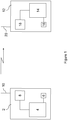
- FIG 1 shows a master device 2 which has a microprocessor 4 which receives a clock signal from an oscillator 6 and which controls analogue radio transmitter circuitry 8.
- the master device 2 also has a radio antenna 10 for transmitting radio signals.
- a slave device 12 which has a microprocessor 14 which receives a clock signal from an oscillator 16 and which controls analogue radio receiving circuitry 18.
- the slave device 12 has a radio antenna 20 for receiving radio signals from the master device 2.
- the microprocessor 4, 14 and analogue circuitry 8, 18 of the master device 2 or slave device 12 may be integrated in a radio-on-a-chip.
- a radio-on-a-chip Such a chip may also comprise the antenna 10, 20 and/or oscillator 6, 16.
- the oscillators 6, 16 may be crystal oscillators or resistor-capacitor oscillators or any other suitable oscillators.
- the master device 2 may also comprise radio receiving circuitry, and the slave device 12 may comprise radio transmitter circuitry, such that bidirectional communication between the two is possible.
- the master device 2 and slave device 12 may be configured to exchange radio data substantially in accordance with the Bluetooth Low Energy (TM) specification.
- TM Bluetooth Low Energy
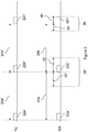
- Figure 3 illustrates schematically a data transmission from the master device 2 to the slave device 12 according to an embodiment of the present invention.
- the horizontal time axis is not to scale (in particular, the sleep period between data packets will typically be many times longer than the listening window).
- Those elements of the master device 2 and slave device 12 which do not relate directly to the timing of the listening windows on the slave device 12 may be in accordance with the Bluetooth Low Energy (TM) specification.
- TM Bluetooth Low Energy
- the master device 2 transmits a succession of data packets 22a', 22b', 22c' at regular intervals, each of which may mark the start of a respective connection event.
- Other data packets may be sent in either direction between the master device 2 and slave device 12 immediately following one of these connection-event data packets 22a', 22b', 22c'.
- the slave device 12 enters sleep mode, in which some or all of its receive circuitry 18 and/or some of its microprocessor logic 16 may be powered down.
- the slave device 12 may use a more accurate oscillator during transmission, and revert to using a lower-power, less accurate oscillator 16 for the clock signal while in sleep mode.
- each of the data packets 22a', 22b', 22c' can be considered to be received instantaneously by the slave device 12.
- the lengths of the intervals 34a, 34b between the successive connection-event data packets 22a', 22b' and 22b', 22c' as measured by the slave device 12 may be different from their lengths 24a', 24b' as measured by the master device 2. While the master device 2 intends to send the connection-event data packets at regular intervals, in reality, the intervals may be inaccurate relative to true time, and further apparent inaccuracy may be present relative to the slave device's 12 clock signal.
- the slave device 12 may adopt a cautious approach and open a relatively wide listening window 28' which starts a relatively long period 30' before the expected arrival of the packet 22b'. It can keep the window 28' open for up to a relatively long maximum period 32' after the expected arrival time, if the packet is not received sooner.
- the slave device 12 compensates for slow-changing drift between the master device 2 and slave device 12 clock signals by noting the actual measured interval 34a between the two most recently received connection-event packets 22a', 22b' and using this measurement to determine when to expect the next data packet 22c' to arrive.
- the size of the interval 34a between the two most recently received data packets 22a', 22b' can be stored in a register or in memory as a variable which is updated continually. This effectively measures the relative timing error between the master and slave clock signals with very low memory requirements, which can be especially advantageous in low-end devices.
- the slave device 12 can enter a ready state - i.e. opens a listening window 36 - a relatively short period 38 before the expected arrival time of the next data packet 22c'.
- This period 38 can be smaller than the equivalent period 30 in the prior-art implementation of Figure 2 , since it only needs to allow for fast-changing clock errors, rather than allowing for both fast-changing and slow-changing clock errors.
- the standard period 38 may be of fixed duration, or it may vary, e.g. depending on packet loss rates.
- the listening window 36 may remain open for up to the same period 40 after the expected arrival time of the data packet 22c', if the packet has not already been received by then.
- the slave device 12 may expect a further data packet after another period of time corresponding to the interval between the two last-received data packets 22a', 22b' but may increase the size of the listening window for this next data packet, to proportionally compensate for the modelled short-term variation relative to the last successfully-received connection-event data packet.
- the listening window may be scaled up in size linearly with the amount of time since the last-received data packet 22b'. After several lost data packets, the connection may be deemed lost, and a resynchronisation process may be initiated.
- the interval between the successive data packets 22a, 22b, 22c may be intended to be one second.
- the maximum relative drift between the master and slave clock signals might typically be 1000 parts per million (ppm), of which slow-changing drift typically accounts for 950 ppm and fast-changing errors typically account for 50 ppm.
- the listening window 28 will be opened one millisecond before the expected arrival of each data packet. Assuming the data packet arrives approximately when expected, this results in the slave device's receive circuitry being powered up unnecessarily on average for one millisecond every second.
- the listening window 36 is opened fifty microseconds before the expected arrival of each data packet. Assuming the data packet arrives approximately when expected, this results in the slave device's 12 receive circuitry 18 being powered up unnecessarily on average for only fifty microseconds every second, resulting in a substantial power saving.
Landscapes
- Engineering & Computer Science (AREA)
- Computer Networks & Wireless Communication (AREA)
- Signal Processing (AREA)
- Mobile Radio Communication Systems (AREA)
- Synchronisation In Digital Transmission Systems (AREA)
Applications Claiming Priority (2)
| Application Number | Priority Date | Filing Date | Title |
|---|---|---|---|
| GB201115517A GB2490974B (en) | 2011-09-08 | 2011-09-08 | Radio communication system |
| PCT/GB2012/052207 WO2013034924A1 (en) | 2011-09-08 | 2012-09-07 | Radio communication system |
Publications (2)
| Publication Number | Publication Date |
|---|---|
| EP2749087A1 EP2749087A1 (en) | 2014-07-02 |
| EP2749087B1 true EP2749087B1 (en) | 2018-06-27 |
Family
ID=44908252
Family Applications (1)
| Application Number | Title | Priority Date | Filing Date |
|---|---|---|---|
| EP12758880.4A Not-in-force EP2749087B1 (en) | 2011-09-08 | 2012-09-07 | Radio communication system |
Country Status (8)
Families Citing this family (21)
| Publication number | Priority date | Publication date | Assignee | Title |
|---|---|---|---|---|
| GB2490974B (en) * | 2011-09-08 | 2014-10-29 | Nordic Semiconductor Asa | Radio communication system |
| US9544075B2 (en) | 2012-02-22 | 2017-01-10 | Qualcomm Incorporated | Platform for wireless identity transmitter and system using short range wireless broadcast |
| US10419907B2 (en) | 2012-02-22 | 2019-09-17 | Qualcomm Incorporated | Proximity application discovery and provisioning |
| US10360593B2 (en) | 2012-04-24 | 2019-07-23 | Qualcomm Incorporated | Retail proximity marketing |
| KR102201616B1 (ko) * | 2014-02-23 | 2021-01-12 | 삼성전자주식회사 | 전자 장치 간의 장치 검색 방법 |
| EP3138328B1 (en) | 2014-05-01 | 2021-04-21 | Nokia Technologies Oy | Method and apparatus for connecting to a node of a mesh network |
| US8990556B1 (en) | 2014-08-13 | 2015-03-24 | Gimbal, Inc. | Sharing beacons |
| CN104615016B (zh) * | 2014-12-08 | 2017-06-30 | 广东欧珀移动通信有限公司 | 一种基于低功耗蓝牙技术控制主机的方法及装置 |
| US9107152B1 (en) | 2015-03-11 | 2015-08-11 | Gimbal, Inc. | Beacon protocol advertising bi-directional communication availability window |
| JP6394452B2 (ja) * | 2015-03-23 | 2018-09-26 | カシオ計算機株式会社 | 無線通信装置、無線通信方法、及びプログラム |
| US10098068B2 (en) * | 2016-02-12 | 2018-10-09 | Semiconductor Components Industries, Llc | Power optimization system and method for low power devices |
| TWI627860B (zh) * | 2016-05-31 | 2018-06-21 | 晨星半導體股份有限公司 | 影音處理裝置與方法 |
| US10045297B1 (en) * | 2017-01-24 | 2018-08-07 | Google Llc | Increased time in a suspended state during network transmissions |
| DE102018004815B4 (de) * | 2018-06-08 | 2019-12-24 | Diehl Metering Systems Gmbh | Verfahren zum Betrieb eines Funkübertragungssystems sowie Anordnung eines Funkübertragungssystems |
| GB201912169D0 (en) | 2019-08-23 | 2019-10-09 | Nordic Semiconductor Asa | Radio apparatus for communicating digital audio streams |
| GB201912412D0 (en) | 2019-08-29 | 2019-10-16 | Forkbeard Tech As | Position determination |
| EP3849249B1 (en) * | 2020-01-09 | 2023-06-14 | Stichting IMEC Nederland | System and method for generating time reference in duty-cycled wireless communications |
| CN114980322A (zh) * | 2021-02-26 | 2022-08-30 | 恩智浦有限公司 | 改进的窗口加宽 |
| CN115913449A (zh) * | 2021-08-03 | 2023-04-04 | 华为技术有限公司 | 数据传输方法和装置 |
| CN115038153B (zh) * | 2022-08-10 | 2022-12-13 | 广州安凯微电子股份有限公司 | 一种低功耗蓝牙芯片休眠模式控制方法及系统 |
| FR3147468A1 (fr) * | 2023-03-30 | 2024-10-04 | Stmicroelectronics International N.V. | Procédé de commande de récepteur de communications |
Family Cites Families (26)
| Publication number | Priority date | Publication date | Assignee | Title |
|---|---|---|---|---|
| US5155479A (en) | 1989-10-17 | 1992-10-13 | Seiko Corp. | Radio receiver with adaptive on-off control |
| JP2501245B2 (ja) * | 1990-12-07 | 1996-05-29 | 日本電信電話株式会社 | 無線呼出用受信機の間欠受信回路 |
| GB9304638D0 (en) * | 1993-03-06 | 1993-04-21 | Ncr Int Inc | Wireless data communication system having power saving function |
| DE60033503T2 (de) * | 2000-06-09 | 2007-11-08 | Motorola, Inc., Schaumburg | Zeitsynchronisierung für Mobile Funksysteme |
| US7023884B2 (en) | 2000-12-19 | 2006-04-04 | Lucent Technologies Inc. | Clock offset estimation with bias correction |
| JP2002209264A (ja) * | 2001-01-11 | 2002-07-26 | Mitsubishi Electric Corp | 移動体端末及びその間欠受信方法 |
| US7120390B2 (en) | 2001-03-21 | 2006-10-10 | Agere Systems Inc. | BLUETOOTH smart offset compensation |
| GB2379581B (en) * | 2001-09-11 | 2005-08-31 | Nec Technologies | Apparatus and method of compensation for signal time-of-arrival variation in a UMTS handset |
| JP2004008027A (ja) * | 2002-06-04 | 2004-01-15 | Japan Science & Technology Corp | cAMPの産生活性を有する新規ペプチド |
| US20040043797A1 (en) * | 2002-08-30 | 2004-03-04 | Shostak Robert E. | Method and apparatus for power conservation in a wireless communication system |
| EP1467584A1 (en) * | 2003-04-11 | 2004-10-13 | Telefonaktiebolaget LM Ericsson (publ) | Method and apparatus for wireless intersystem handover |
| US7457973B2 (en) * | 2003-06-20 | 2008-11-25 | Texas Instruments Incorporated | System and method for prioritizing data transmission and transmitting scheduled wake-up times to network stations based on downlink transmission duration |
| US7321788B2 (en) * | 2003-09-11 | 2008-01-22 | Honeywell International, Inc. | Synchronizing RF system |
| US7197341B2 (en) * | 2003-12-22 | 2007-03-27 | Interdigital Technology Corporation | Precise sleep timer using a low-cost and low-accuracy clock |
| US7496774B2 (en) * | 2004-06-04 | 2009-02-24 | Broadcom Corporation | Method and system for generating clocks for standby mode operation in a mobile communication device |
| US20060056322A1 (en) * | 2004-09-10 | 2006-03-16 | Simpson Floyd D | Method for updating a timer function in a mobile station in a wireless local area network |
| KR100637079B1 (ko) * | 2005-02-17 | 2006-10-23 | 삼성전자주식회사 | 트랜시버의 턴-온 시간을 적응적으로 제어하는 디바이스 및트랜시버의 턴-온 시간 제어방법 |
| US7606602B2 (en) * | 2005-08-11 | 2009-10-20 | Toshiba America Research, Inc. | Reducing power consumption of Wi-Fi enabled mobile devices |
| JP4928864B2 (ja) * | 2006-08-11 | 2012-05-09 | 株式会社オサシ・テクノス | ネットワークシステム |
| CN101601264B (zh) * | 2007-02-01 | 2014-08-20 | Nxp股份有限公司 | 控制移动设备中的唤醒时间 |
| JP4558812B2 (ja) * | 2008-03-13 | 2010-10-06 | 日本電信電話株式会社 | 間欠受信装置 |
| US8170482B2 (en) * | 2008-08-01 | 2012-05-01 | Qualcomm Incorporated | Method and apparatus for receiving a transmission at a receiver |
| KR101179931B1 (ko) | 2008-12-11 | 2012-09-07 | 한국전자통신연구원 | 무선 통신 시스템에서 타이밍 옵셋 추정 장치 및 방법 |
| US20100303185A1 (en) * | 2009-06-02 | 2010-12-02 | Jacobus Cornelis Haartsen | Methods of Operating Wireless Communications Devices Including Detecting Times of Receipt of Packets and Related Devices |
| US20120275366A1 (en) * | 2011-04-29 | 2012-11-01 | Nicholas William Anderson | Switching activation of ue receviers |
| GB2490974B (en) * | 2011-09-08 | 2014-10-29 | Nordic Semiconductor Asa | Radio communication system |
-
2011
- 2011-09-08 GB GB201115517A patent/GB2490974B/en not_active Expired - Fee Related
-
2012
- 2012-09-06 TW TW101132488A patent/TWI552553B/zh not_active IP Right Cessation
- 2012-09-07 KR KR1020147009200A patent/KR20140060570A/ko not_active Ceased
- 2012-09-07 CN CN201280043839.2A patent/CN103947262B/zh not_active Expired - Fee Related
- 2012-09-07 EP EP12758880.4A patent/EP2749087B1/en not_active Not-in-force
- 2012-09-07 US US14/342,765 patent/US9398534B2/en active Active
- 2012-09-07 WO PCT/GB2012/052207 patent/WO2013034924A1/en active Application Filing
- 2012-09-07 JP JP2014529069A patent/JP2014526821A/ja active Pending
-
2016
- 2016-06-15 US US15/183,706 patent/US10064133B2/en active Active
Non-Patent Citations (1)
| Title |
|---|
| None * |
Also Published As
| Publication number | Publication date |
|---|---|
| US10064133B2 (en) | 2018-08-28 |
| TW201312977A (zh) | 2013-03-16 |
| GB2490974A (en) | 2012-11-21 |
| CN103947262B (zh) | 2018-01-19 |
| WO2013034924A1 (en) | 2013-03-14 |
| KR20140060570A (ko) | 2014-05-20 |
| US9398534B2 (en) | 2016-07-19 |
| US20160295508A1 (en) | 2016-10-06 |
| GB2490974B (en) | 2014-10-29 |
| TWI552553B (zh) | 2016-10-01 |
| EP2749087A1 (en) | 2014-07-02 |
| US20150109978A1 (en) | 2015-04-23 |
| CN103947262A (zh) | 2014-07-23 |
| GB201115517D0 (en) | 2011-10-26 |
| JP2014526821A (ja) | 2014-10-06 |
Similar Documents
| Publication | Publication Date | Title |
|---|---|---|
| EP2749087B1 (en) | Radio communication system | |
| EP2745582B1 (en) | Beacon synchronization in wifi based systems | |
| CN101855868B (zh) | 用于在异步无线通信网络中发送信息分组的方法及实现该方法的网络节点 | |
| EP2457332B1 (en) | Method and apparatus for reduced power consumption when operating as a bluetooth low energy device | |
| TWI473513B (zh) | 無線網路裝置及其積體電路 | |
| US9510289B1 (en) | In system calibration of wake up timer | |
| EP2854458B1 (en) | Wireless sensor time synchronization | |
| CN106131947A (zh) | 一种无线网络设备间时钟同步的方法 | |
| EP3039914B1 (en) | Method and apparatuses for discontinuous reception cycle estimation by data packet monitoring | |
| US11777862B2 (en) | Method of receiver window widening and autodrift calculation using packet timestamping | |
| KR102151456B1 (ko) | 무선 단말의 전력 소모를 제어하는 방법 및 장치 | |
| US20100197228A1 (en) | Clock synchronization method for a short range wireless communication network | |
| EP3866019B1 (en) | Clock-error estimation for two-clock electronic device | |
| CA2923402A1 (en) | Low power data transmission protocol | |
| JP2015111916A (ja) | BluetoothLowEnergyデバイスとして動作する時の低消費電力化のための方法および装置 | |
| US20110164710A1 (en) | Transmission timing adjustment in radio systems | |
| US20240098668A1 (en) | Calibration of a low frequency oscillator using a high frequency oscillator as a reference clock | |
| Lin et al. | Work or Sleep: Freshness-Aware Energy Scheduling for Wireless Powered Communication Networks with Interference Consideration | |
| Krzak | Simulation framework for modelling energy consumption in ultra-low duty cycle mobile ad-hoc networks | |
| Blanckenstein et al. | Energy-efficient clock synchronization using wake-up receivers |
Legal Events
| Date | Code | Title | Description |
|---|---|---|---|
| PUAI | Public reference made under article 153(3) epc to a published international application that has entered the european phase |
Free format text: ORIGINAL CODE: 0009012 |
|
| 17P | Request for examination filed |
Effective date: 20140311 |
|
| AK | Designated contracting states |
Kind code of ref document: A1 Designated state(s): AL AT BE BG CH CY CZ DE DK EE ES FI FR GB GR HR HU IE IS IT LI LT LU LV MC MK MT NL NO PL PT RO RS SE SI SK SM TR |
|
| DAX | Request for extension of the european patent (deleted) | ||
| GRAP | Despatch of communication of intention to grant a patent |
Free format text: ORIGINAL CODE: EPIDOSNIGR1 |
|
| STAA | Information on the status of an ep patent application or granted ep patent |
Free format text: STATUS: GRANT OF PATENT IS INTENDED |
|
| INTG | Intention to grant announced |
Effective date: 20170807 |
|
| GRAJ | Information related to disapproval of communication of intention to grant by the applicant or resumption of examination proceedings by the epo deleted |
Free format text: ORIGINAL CODE: EPIDOSDIGR1 |
|
| STAA | Information on the status of an ep patent application or granted ep patent |
Free format text: STATUS: REQUEST FOR EXAMINATION WAS MADE |
|
| INTC | Intention to grant announced (deleted) | ||
| GRAP | Despatch of communication of intention to grant a patent |
Free format text: ORIGINAL CODE: EPIDOSNIGR1 |
|
| STAA | Information on the status of an ep patent application or granted ep patent |
Free format text: STATUS: GRANT OF PATENT IS INTENDED |
|
| INTG | Intention to grant announced |
Effective date: 20180206 |
|
| GRAS | Grant fee paid |
Free format text: ORIGINAL CODE: EPIDOSNIGR3 |
|
| GRAA | (expected) grant |
Free format text: ORIGINAL CODE: 0009210 |
|
| STAA | Information on the status of an ep patent application or granted ep patent |
Free format text: STATUS: THE PATENT HAS BEEN GRANTED |
|
| AK | Designated contracting states |
Kind code of ref document: B1 Designated state(s): AL AT BE BG CH CY CZ DE DK EE ES FI FR GB GR HR HU IE IS IT LI LT LU LV MC MK MT NL NO PL PT RO RS SE SI SK SM TR |
|
| REG | Reference to a national code |
Ref country code: GB Ref legal event code: FG4D |
|
| RIN1 | Information on inventor provided before grant (corrected) |
Inventor name: STAPLETON, JOEL DAVID Inventor name: BERNTSEN, FRANK Inventor name: ENGELIEN-LOPES, DAVID ALEXANDRE |
|
| REG | Reference to a national code |
Ref country code: AT Ref legal event code: REF Ref document number: 1013428 Country of ref document: AT Kind code of ref document: T Effective date: 20180715 |
|
| REG | Reference to a national code |
Ref country code: IE Ref legal event code: FG4D |
|
| REG | Reference to a national code |
Ref country code: DE Ref legal event code: R096 Ref document number: 602012047852 Country of ref document: DE |
|
| REG | Reference to a national code |
Ref country code: FR Ref legal event code: PLFP Year of fee payment: 7 |
|
| PG25 | Lapsed in a contracting state [announced via postgrant information from national office to epo] |
Ref country code: NO Free format text: LAPSE BECAUSE OF FAILURE TO SUBMIT A TRANSLATION OF THE DESCRIPTION OR TO PAY THE FEE WITHIN THE PRESCRIBED TIME-LIMIT Effective date: 20180927 Ref country code: LT Free format text: LAPSE BECAUSE OF FAILURE TO SUBMIT A TRANSLATION OF THE DESCRIPTION OR TO PAY THE FEE WITHIN THE PRESCRIBED TIME-LIMIT Effective date: 20180627 Ref country code: SE Free format text: LAPSE BECAUSE OF FAILURE TO SUBMIT A TRANSLATION OF THE DESCRIPTION OR TO PAY THE FEE WITHIN THE PRESCRIBED TIME-LIMIT Effective date: 20180627 Ref country code: FI Free format text: LAPSE BECAUSE OF FAILURE TO SUBMIT A TRANSLATION OF THE DESCRIPTION OR TO PAY THE FEE WITHIN THE PRESCRIBED TIME-LIMIT Effective date: 20180627 Ref country code: BG Free format text: LAPSE BECAUSE OF FAILURE TO SUBMIT A TRANSLATION OF THE DESCRIPTION OR TO PAY THE FEE WITHIN THE PRESCRIBED TIME-LIMIT Effective date: 20180927 |
|
| REG | Reference to a national code |
Ref country code: NL Ref legal event code: MP Effective date: 20180627 |
|
| REG | Reference to a national code |
Ref country code: LT Ref legal event code: MG4D |
|
| PG25 | Lapsed in a contracting state [announced via postgrant information from national office to epo] |
Ref country code: RS Free format text: LAPSE BECAUSE OF FAILURE TO SUBMIT A TRANSLATION OF THE DESCRIPTION OR TO PAY THE FEE WITHIN THE PRESCRIBED TIME-LIMIT Effective date: 20180627 Ref country code: LV Free format text: LAPSE BECAUSE OF FAILURE TO SUBMIT A TRANSLATION OF THE DESCRIPTION OR TO PAY THE FEE WITHIN THE PRESCRIBED TIME-LIMIT Effective date: 20180627 Ref country code: GR Free format text: LAPSE BECAUSE OF FAILURE TO SUBMIT A TRANSLATION OF THE DESCRIPTION OR TO PAY THE FEE WITHIN THE PRESCRIBED TIME-LIMIT Effective date: 20180928 Ref country code: HR Free format text: LAPSE BECAUSE OF FAILURE TO SUBMIT A TRANSLATION OF THE DESCRIPTION OR TO PAY THE FEE WITHIN THE PRESCRIBED TIME-LIMIT Effective date: 20180627 |
|
| REG | Reference to a national code |
Ref country code: AT Ref legal event code: MK05 Ref document number: 1013428 Country of ref document: AT Kind code of ref document: T Effective date: 20180627 |
|
| PG25 | Lapsed in a contracting state [announced via postgrant information from national office to epo] |
Ref country code: NL Free format text: LAPSE BECAUSE OF FAILURE TO SUBMIT A TRANSLATION OF THE DESCRIPTION OR TO PAY THE FEE WITHIN THE PRESCRIBED TIME-LIMIT Effective date: 20180627 |
|
| PG25 | Lapsed in a contracting state [announced via postgrant information from national office to epo] |
Ref country code: SK Free format text: LAPSE BECAUSE OF FAILURE TO SUBMIT A TRANSLATION OF THE DESCRIPTION OR TO PAY THE FEE WITHIN THE PRESCRIBED TIME-LIMIT Effective date: 20180627 Ref country code: EE Free format text: LAPSE BECAUSE OF FAILURE TO SUBMIT A TRANSLATION OF THE DESCRIPTION OR TO PAY THE FEE WITHIN THE PRESCRIBED TIME-LIMIT Effective date: 20180627 Ref country code: AT Free format text: LAPSE BECAUSE OF FAILURE TO SUBMIT A TRANSLATION OF THE DESCRIPTION OR TO PAY THE FEE WITHIN THE PRESCRIBED TIME-LIMIT Effective date: 20180627 Ref country code: IS Free format text: LAPSE BECAUSE OF FAILURE TO SUBMIT A TRANSLATION OF THE DESCRIPTION OR TO PAY THE FEE WITHIN THE PRESCRIBED TIME-LIMIT Effective date: 20181027 Ref country code: PL Free format text: LAPSE BECAUSE OF FAILURE TO SUBMIT A TRANSLATION OF THE DESCRIPTION OR TO PAY THE FEE WITHIN THE PRESCRIBED TIME-LIMIT Effective date: 20180627 Ref country code: RO Free format text: LAPSE BECAUSE OF FAILURE TO SUBMIT A TRANSLATION OF THE DESCRIPTION OR TO PAY THE FEE WITHIN THE PRESCRIBED TIME-LIMIT Effective date: 20180627 Ref country code: CZ Free format text: LAPSE BECAUSE OF FAILURE TO SUBMIT A TRANSLATION OF THE DESCRIPTION OR TO PAY THE FEE WITHIN THE PRESCRIBED TIME-LIMIT Effective date: 20180627 |
|
| PG25 | Lapsed in a contracting state [announced via postgrant information from national office to epo] |
Ref country code: IT Free format text: LAPSE BECAUSE OF FAILURE TO SUBMIT A TRANSLATION OF THE DESCRIPTION OR TO PAY THE FEE WITHIN THE PRESCRIBED TIME-LIMIT Effective date: 20180627 Ref country code: ES Free format text: LAPSE BECAUSE OF FAILURE TO SUBMIT A TRANSLATION OF THE DESCRIPTION OR TO PAY THE FEE WITHIN THE PRESCRIBED TIME-LIMIT Effective date: 20180627 Ref country code: SM Free format text: LAPSE BECAUSE OF FAILURE TO SUBMIT A TRANSLATION OF THE DESCRIPTION OR TO PAY THE FEE WITHIN THE PRESCRIBED TIME-LIMIT Effective date: 20180627 |
|
| REG | Reference to a national code |
Ref country code: DE Ref legal event code: R097 Ref document number: 602012047852 Country of ref document: DE |
|
| PG25 | Lapsed in a contracting state [announced via postgrant information from national office to epo] |
Ref country code: MC Free format text: LAPSE BECAUSE OF FAILURE TO SUBMIT A TRANSLATION OF THE DESCRIPTION OR TO PAY THE FEE WITHIN THE PRESCRIBED TIME-LIMIT Effective date: 20180627 |
|
| REG | Reference to a national code |
Ref country code: CH Ref legal event code: PL |
|
| PLBE | No opposition filed within time limit |
Free format text: ORIGINAL CODE: 0009261 |
|
| STAA | Information on the status of an ep patent application or granted ep patent |
Free format text: STATUS: NO OPPOSITION FILED WITHIN TIME LIMIT |
|
| PG25 | Lapsed in a contracting state [announced via postgrant information from national office to epo] |
Ref country code: DK Free format text: LAPSE BECAUSE OF FAILURE TO SUBMIT A TRANSLATION OF THE DESCRIPTION OR TO PAY THE FEE WITHIN THE PRESCRIBED TIME-LIMIT Effective date: 20180627 |
|
| 26N | No opposition filed |
Effective date: 20190328 |
|
| REG | Reference to a national code |
Ref country code: BE Ref legal event code: MM Effective date: 20180930 |
|
| REG | Reference to a national code |
Ref country code: IE Ref legal event code: MM4A |
|
| PG25 | Lapsed in a contracting state [announced via postgrant information from national office to epo] |
Ref country code: LU Free format text: LAPSE BECAUSE OF NON-PAYMENT OF DUE FEES Effective date: 20180907 |
|
| PG25 | Lapsed in a contracting state [announced via postgrant information from national office to epo] |
Ref country code: IE Free format text: LAPSE BECAUSE OF NON-PAYMENT OF DUE FEES Effective date: 20180907 |
|
| PG25 | Lapsed in a contracting state [announced via postgrant information from national office to epo] |
Ref country code: CH Free format text: LAPSE BECAUSE OF NON-PAYMENT OF DUE FEES Effective date: 20180930 Ref country code: LI Free format text: LAPSE BECAUSE OF NON-PAYMENT OF DUE FEES Effective date: 20180930 Ref country code: SI Free format text: LAPSE BECAUSE OF FAILURE TO SUBMIT A TRANSLATION OF THE DESCRIPTION OR TO PAY THE FEE WITHIN THE PRESCRIBED TIME-LIMIT Effective date: 20180627 Ref country code: BE Free format text: LAPSE BECAUSE OF NON-PAYMENT OF DUE FEES Effective date: 20180930 |
|
| PG25 | Lapsed in a contracting state [announced via postgrant information from national office to epo] |
Ref country code: AL Free format text: LAPSE BECAUSE OF FAILURE TO SUBMIT A TRANSLATION OF THE DESCRIPTION OR TO PAY THE FEE WITHIN THE PRESCRIBED TIME-LIMIT Effective date: 20180627 |
|
| PG25 | Lapsed in a contracting state [announced via postgrant information from national office to epo] |
Ref country code: MT Free format text: LAPSE BECAUSE OF NON-PAYMENT OF DUE FEES Effective date: 20180907 |
|
| PG25 | Lapsed in a contracting state [announced via postgrant information from national office to epo] |
Ref country code: TR Free format text: LAPSE BECAUSE OF FAILURE TO SUBMIT A TRANSLATION OF THE DESCRIPTION OR TO PAY THE FEE WITHIN THE PRESCRIBED TIME-LIMIT Effective date: 20180627 |
|
| PG25 | Lapsed in a contracting state [announced via postgrant information from national office to epo] |
Ref country code: HU Free format text: LAPSE BECAUSE OF FAILURE TO SUBMIT A TRANSLATION OF THE DESCRIPTION OR TO PAY THE FEE WITHIN THE PRESCRIBED TIME-LIMIT; INVALID AB INITIO Effective date: 20120907 Ref country code: PT Free format text: LAPSE BECAUSE OF FAILURE TO SUBMIT A TRANSLATION OF THE DESCRIPTION OR TO PAY THE FEE WITHIN THE PRESCRIBED TIME-LIMIT Effective date: 20180627 |
|
| PG25 | Lapsed in a contracting state [announced via postgrant information from national office to epo] |
Ref country code: CY Free format text: LAPSE BECAUSE OF FAILURE TO SUBMIT A TRANSLATION OF THE DESCRIPTION OR TO PAY THE FEE WITHIN THE PRESCRIBED TIME-LIMIT Effective date: 20180627 Ref country code: MK Free format text: LAPSE BECAUSE OF NON-PAYMENT OF DUE FEES Effective date: 20180627 |
|
| PGFP | Annual fee paid to national office [announced via postgrant information from national office to epo] |
Ref country code: GB Payment date: 20230823 Year of fee payment: 12 |
|
| PGFP | Annual fee paid to national office [announced via postgrant information from national office to epo] |
Ref country code: FR Payment date: 20230822 Year of fee payment: 12 Ref country code: DE Payment date: 20230822 Year of fee payment: 12 |
|
| REG | Reference to a national code |
Ref country code: DE Ref legal event code: R119 Ref document number: 602012047852 Country of ref document: DE |
|
| GBPC | Gb: european patent ceased through non-payment of renewal fee |
Effective date: 20240907 |
|
| PG25 | Lapsed in a contracting state [announced via postgrant information from national office to epo] |
Ref country code: DE Free format text: LAPSE BECAUSE OF NON-PAYMENT OF DUE FEES Effective date: 20250401 |
|
| PG25 | Lapsed in a contracting state [announced via postgrant information from national office to epo] |
Ref country code: GB Free format text: LAPSE BECAUSE OF NON-PAYMENT OF DUE FEES Effective date: 20240907 |
|
| PG25 | Lapsed in a contracting state [announced via postgrant information from national office to epo] |
Ref country code: FR Free format text: LAPSE BECAUSE OF NON-PAYMENT OF DUE FEES Effective date: 20240930 |