EP2748116B1 - Method for producing optical fiber having controlled index perturbations - Google Patents
Method for producing optical fiber having controlled index perturbations Download PDFInfo
- Publication number
- EP2748116B1 EP2748116B1 EP12766491.0A EP12766491A EP2748116B1 EP 2748116 B1 EP2748116 B1 EP 2748116B1 EP 12766491 A EP12766491 A EP 12766491A EP 2748116 B1 EP2748116 B1 EP 2748116B1
- Authority
- EP
- European Patent Office
- Prior art keywords
- optical fiber
- fiber
- index perturbations
- perturbation
- introducing
- Prior art date
- Legal status (The legal status is an assumption and is not a legal conclusion. Google has not performed a legal analysis and makes no representation as to the accuracy of the status listed.)
- Not-in-force
Links
Images


Classifications
-
- C—CHEMISTRY; METALLURGY
- C03—GLASS; MINERAL OR SLAG WOOL
- C03B—MANUFACTURE, SHAPING, OR SUPPLEMENTARY PROCESSES
- C03B37/00—Manufacture or treatment of flakes, fibres, or filaments from softened glass, minerals, or slags
- C03B37/01—Manufacture of glass fibres or filaments
- C03B37/02—Manufacture of glass fibres or filaments by drawing or extruding, e.g. direct drawing of molten glass from nozzles; Cooling fins therefor
- C03B37/025—Manufacture of glass fibres or filaments by drawing or extruding, e.g. direct drawing of molten glass from nozzles; Cooling fins therefor from reheated softened tubes, rods, fibres or filaments, e.g. drawing fibres from preforms
- C03B37/027—Fibres composed of different sorts of glass, e.g. glass optical fibres
- C03B37/02745—Fibres having rotational spin around the central longitudinal axis, e.g. alternating +/- spin to reduce polarisation mode dispersion
-
- C—CHEMISTRY; METALLURGY
- C03—GLASS; MINERAL OR SLAG WOOL
- C03B—MANUFACTURE, SHAPING, OR SUPPLEMENTARY PROCESSES
- C03B37/00—Manufacture or treatment of flakes, fibres, or filaments from softened glass, minerals, or slags
- C03B37/01—Manufacture of glass fibres or filaments
- C03B37/02—Manufacture of glass fibres or filaments by drawing or extruding, e.g. direct drawing of molten glass from nozzles; Cooling fins therefor
- C03B37/025—Manufacture of glass fibres or filaments by drawing or extruding, e.g. direct drawing of molten glass from nozzles; Cooling fins therefor from reheated softened tubes, rods, fibres or filaments, e.g. drawing fibres from preforms
- C03B37/027—Fibres composed of different sorts of glass, e.g. glass optical fibres
- C03B37/02763—Fibres having axial variations, e.g. axially varying diameter, material or optical properties
-
- C—CHEMISTRY; METALLURGY
- C03—GLASS; MINERAL OR SLAG WOOL
- C03B—MANUFACTURE, SHAPING, OR SUPPLEMENTARY PROCESSES
- C03B2203/00—Fibre product details, e.g. structure, shape
- C03B2203/02—External structure or shape details
- C03B2203/06—Axial perturbations, e.g. twist, by torsion, undulating, crimped
-
- C—CHEMISTRY; METALLURGY
- C03—GLASS; MINERAL OR SLAG WOOL
- C03B—MANUFACTURE, SHAPING, OR SUPPLEMENTARY PROCESSES
- C03B2203/00—Fibre product details, e.g. structure, shape
- C03B2203/10—Internal structure or shape details
- C03B2203/18—Axial perturbations, e.g. in refractive index or composition
- C03B2203/20—Axial perturbations, e.g. in refractive index or composition helical
-
- Y—GENERAL TAGGING OF NEW TECHNOLOGICAL DEVELOPMENTS; GENERAL TAGGING OF CROSS-SECTIONAL TECHNOLOGIES SPANNING OVER SEVERAL SECTIONS OF THE IPC; TECHNICAL SUBJECTS COVERED BY FORMER USPC CROSS-REFERENCE ART COLLECTIONS [XRACs] AND DIGESTS
- Y02—TECHNOLOGIES OR APPLICATIONS FOR MITIGATION OR ADAPTATION AGAINST CLIMATE CHANGE
- Y02P—CLIMATE CHANGE MITIGATION TECHNOLOGIES IN THE PRODUCTION OR PROCESSING OF GOODS
- Y02P40/00—Technologies relating to the processing of minerals
- Y02P40/50—Glass production, e.g. reusing waste heat during processing or shaping
- Y02P40/57—Improving the yield, e-g- reduction of reject rates
Definitions
- the present invention generally relates to a method for forming optical fiber and, more particularly relates to a method of introducing perturbations into the optical fiber during the fiber draw process.
- WO 2006/058551 A1 discloses a method, and a system based on said method, for imparting to an optical fiber a predetermined rotation about its axis, wherein the fiber is rotated by way of a frictional force acting on the fiber while it is advanced in a predetermined direction.
- US 2006/093294 A1 discloses an optical fiber for the transmission of electromagnetic energy, which can have increased input power threshold for the onset of Stimulated Brillouin Scattering (SBS) and methods for fabricating and/or using such a fiber.
- SBS Stimulated Brillouin Scattering
- a method for producing an optical fiber includes the step of drawing a bare optical fiber from a heated glass source in a furnace.
- the method further includes the step of introducing index perturbations to the bare optical fiber via a plurality of perturbation sources arranged at different azimuthal locations, wherein the index perturbations are introduced by the plurality of perturbation sources at different frequencies to cause stress in the bare optical fiber.
- a method for producing an optical fiber includes the step of drawing a bare optical fiber from a heated glass source in a furnace.
- the method further includes the step of introducing index perturbations to the bare optical fiber via a plurality of perturbation sources arranged at a plurality of different azimuthal locations and at different locations along the axial length of the bare optical fiber, wherein the index perturbations are introduced synchronously by the plurality of perturbation sources in a generally helical pattern on the outside surface of the bare optical fiber to cause stress in the bare optical fiber.
- the optical fiber production system and method produces optical fibers through the use of a draw process and introduces perturbations to the optical fiber to introduce mode coupling in the glass level and improve the bandwidth of multimode fibers (MMF).
- MMF multimode fibers
- bare optical fiber as used herein means an optical fiber directly drawn from a preform and prior to applying a protective coating layer to its outer surface (e.g., prior to the bare optical fiber being coated with a polymeric based material).
- index perturbation as used herein means a local change of refractive index in the fiber.
- the optical fiber production system and method allows for the formation of optical fiber to include the introduction of index perturbations, particularly for multimode fiber, and to distribute such perturbations in various orientations along the fiber length as disclosed herein.
- an optical fiber production system 10 is generally shown for producing an optical fiber pursuant to a fiber production method, according to one embodiment.
- the system 10 includes a furnace 12 that may be heated to a temperature of about 2,000°C, according to one example.
- a heated glass source commonly referred to as an optical fiber preform 14, is placed in the furnace 12 and fiber is drawn therefrom to create a bare optical fiber 18.
- the preform 14 may be constructed of any glass or material and may be doped suitable for the manufacture of optical fibers.
- the bare optical fiber 18 may be cooled to a desired temperature using known techniques, such as a slow-cooling treatment device (not shown) or other technique such that the fiber 18 exiting the outlet 16 of furnace 12 is within a desired temperature range.
- the optical fiber 18 exiting the exit orifice 16 of furnace 12 is drawn at a draw speed, has a fiber diameter and a fiber temperature such that the fiber 18 is in a molten state that may be partially solidified and further solidifies as it cools.
- one or more centering devices may be employed to center the bare optical fiber 18 as it exits the exit orifice 16.
- an index perturbation assembly 20 is located downstream of the exit orifice 16 and arranged to introduce index perturbations to the optical fiber 18.
- the index perturbation assembly 20 includes a plurality of perturbation sources arranged at different azimuthal locations at different angles for introducing controlled index perturbations onto the outer surface of the bare optical fiber 18.
- the perturbation sources include a plurality of controlled gas blowing devices 30A-30C, each configured to blow gas onto the outer surface of the optical fiber 18 to cool the optical fiber 18 locally and thereby cause index perturbations in the outer surface.
- the gas is blown onto the fiber 18 at a location where the fiber 18 has a temperature roughly around or between the glass transition temperature (close to the root or close to where the fiber exits the furnace) and the fictive temperature.
- cool gas such as air
- the index perturbations are distributed over various fiber orientations along the axial length of the optical fiber 18. The controlled introduction of the index perturbations enhances the bandwidth of multimode fiber while advantageously eliminating or reducing the need for fiber spinning or twisting.
- index perturbations are introduced from several different azimuthal locations, and each perturbation device 30A-30C may be located at different locations along the axial length (i.e., different axial lengths) of the optical fiber 18.
- the method disclosed herein allows the index perturbations to be introduced at a desired high frequency and orientation so that the mode coupling is more effective and bandwidth improvement occurs at a shorter length regime.
- fiber spinning may be eliminated, or some reduced fiber spinning can be used in conjunction with the method, according to various embodiments.
- the bare optical fiber 18 is then subjected to a coating unit 22 where a primary protective coating layer is applied to the outer surface of the bare optical fiber 18.
- the coated fiber then passes through a curing unit 24 having ultraviolet lamps to cure the coating.
- the optical fiber 18 with the protective layer can pass through a variety of processing stages within the production system 10 such as one or more rollers 26 and tractor 28.
- the tractor 28 may be used to provide the necessary tension on the optical fiber 18 as it is drawn through the entire fiber production system and eventually wound onto a storage spool. It should be appreciated that the tractor 28 may be controlled so as to control the draw speed of the fiber 18.
- the index perturbation assembly 20 shown in Figure 1 is further illustrated, according to the first embodiment.
- the assembly 20 includes three index perturbation sources shown as gas blowing devices 30A-30C arranged equiangularly at 120° azimiuthal spacings from one another around the outer surface of the optical fiber 18.
- the gas blowing devices 30A-30C are each located at a different locations along the axial length of the optical fiber 18 relative to each other for blowing gas, in a controlled fashion, onto the outer surface of the optical fiber 18 at a desired angle of incidence.
- Each gas blowing device 30A and 30B includes gas blowing needles 32A-32C oriented to direct forced gas onto the outer surface of optical fiber 18.
- the gas blowing needles 32A-32C continuously output a stream of forced cooling gas supplied from a gas source, according to one embodiment.
- the gas may include any suitable cooling gas including nitrogen, helium, oxygen or air containing a mixture of gases.
- Each perturbation device 30-30C also includes an optical chopper or shutter 34A-34C shown as a disc having an open window pattern defined by one or more openings 36A-36C.
- Each optical chopper or shutter 34A-34C has one or more window openings that allow gas to pass through to reach the fiber 18 and solid areas that block the passage of gas to the fiber 18.
- Each of choppers 34A-34C is aligned with the corresponding gas blowing needles 32A-32C to control the introduction of forced gas from the needles 32A-32C onto the outer surface of optical fiber 18.
- the optical choppers or shutters 34A-34C are rotated via corresponding motors 38A-38C, each of which is controlled by motor control circuitry, shown as a microprocessor 40.
- the choppers or shutters 34A-34C operate to chop or shutter the forced gas stream output from the corresponding needles 32A-32C.
- the choppers 34A-34C each have a desired shape open window and the motors 38A-38C are controlled to rotate the choppers 34A-34C to achieve a desired gas injection onto the outer surface of optical fiber 18.
- Each of the choppers 34A-34C is rotated by the corresponding motor 38A-38C at an angular frequency ⁇ (radians/second) or frequency F (hertz) and is implemented such that gas blows onto the fiber for a controlled period of time during one full rotation.
- the index perturbations are introduced asynchronously at different locations along the axial length of the fiber by the plurality of plurality of perturbation sources 30A-30C in a generally helical pattern on the outside surface of the fiber 18.
- the motors 38A-38C operate with a controlled phase and at a synchronized frequency.
- the air blowing behavior can be described by the following function: ⁇ i (z - z i , ⁇ i , ⁇ i , v), where z ⁇ is the initial position of the i-th perturbation device, ⁇ i is the initial phase of the chopper window, v is the draw speed, and ⁇ i is the angular frequency of the chopper rotation.
- the choppers 34A-34C and air blowing devices 32A-32C can be installed and controlled so that the open windows 36A-36C of the respective choppers 34A-34C open for forced gas to blow through are synchronous to each other.
- the first perturbation device 30A may be positioned relative to the fiber at an axial position of 0 meters
- the second perturbation device 30B may be positioned at an axial position of 0.1 meters
- the third perturbation device 30C may be positioned at an axial position of 0.2 meters.
- the fiber draw speed may be set at 10 meters per second in this example.
- the optical choppers 34A-34C may be rotated at the same frequency, such as 100 Hz.
- the phase for each chopper is set at 0, ⁇ /3 and 2 ⁇ /3 radians.
- Gas blowing needles 32A-32C are directed to impinge on the optical fiber 18 from angles of 0 , ⁇ / 3 and 2 ⁇ /3 radians.
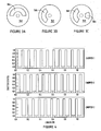
- the opening and closing of the windows 36A-36C of choppers 34A-34C as the choppers 34A-34C rotate are illustrated in Figure 4 , according to one synchronous controlled embodiment.
- only one chopper has a window 36A-36C open for cooling gas, such as air, to blow through the corresponding window and onto the outer surface of optical fiber 18.
- the process alternates through each chopper 34A-34C and may be repeated indefinitely.
- the motor speed that drives the choppers 34A-34C can be controlled so that a desired frequency for the mode coupling occurs.
- the spatial frequency can be increased by implementing multiple open and closed positions within one or more choppers 34A-34C, according to other embodiments.
- Figures 3A-3C illustrate three examples of optical choppers that maybe employed by each of gas blowing devices 30A-30C.
- the optical chopper 34A illustrated in Figure 3A has an open window 36A extending 180° to enable a stream of forced gas to flow through the window 36A one-half revolution or one-half of the time.
- the chopper 34A shown in Figure 3B has a window 36A extending 120° so as to allow a stream of forced gas flow through the window 36A one-third of each rotation or one-third of the time.
- the chopper 34A shown in Figure 3C has a complex window arrangement which includes two windows 36A that allows for mixing of different frequency components.
- the number of windows employed within each chopper 34A-34C is defined as a chopper multiplier.
- a spatial period of the mode coupling pattern of 0.03 meters or 3 centimeters can be achieved.
- the capability of the motors 38A-38C and choppers 34A-34C allows for the generation of a spatial period of 1 millimeter or less, when desired.
- ten (10) equiangularly spaced open windows 36A maybe employed within a complete revolution of each chopper, such that the spatial frequency of the blowing pattern on the fiber 18 is multiplied by a factor of 10. In this way, a spatial frequency can be achieved that is otherwise difficult to achieve.
- the method of producing an optical fiber may introduce index perturbations to the optical fiber via a plurality of perturbation sources arranged at different azimuthal locations, wherein the index perturbations are introduced by the plurality of perturbation sources at different frequencies.
- an asynchronous index perturbation introduction scheme can be implemented by setting the drive motor frequencies to slightly different values relative to each motor so that the beating between different frequencies will allow opening of the choppers 34A-34C at different times resulting in asymmetry of the fiber stress distributed along the fiber in high frequencies. This may be achieved by the control circuitry, such as microprocessor 40, controlling the individual motor frequencies to achieve a desired rotational speed that is different from one another.
- the chopper frequency may be chosen so that the first chopper 34A is rotated at a frequency of 85 Hz, the second chopper 34B is rotated at a frequency of 100 Hz, and the third chopper 34C is rotated at a frequency of 115 Hz.
- the chopper status is illustrated in Figure 5 , according to this example.
- one or more choppers are open for cool gas to blow through the open window to the outer surface of the optical fiber 18. Because of the beating due to different motor speeds associated with each chopper, the fiber 18 at different positions sees a complex pattern mixing very different frequency components which may help generate mode coupling along the length of the multimode fiber.
- the perturbation assembly 20 is shown employing three perturbation sources 30A-30C, it should be appreciated that a greater number of index perturbation devices may be employed. According to one embodiment, the number of index perturbation devices is in the range of 3 to 20, and may be in the range of 3-6. While the spacing of the choppers is shown as equiangularly, it should be appreciated that the spacing may otherwise be uniform or non-uniform. While the axial positioning of the perturbation devices 30A-30C is shown to be at different axial locations along the length of the optical fiber 18, it should be appreciated that the perturbation devices may be employed at the same axial location or length of the fiber 18.
- the windows may be angularly equally spaced or non-equally spaced.
- the motors maybe modulated so that the choppers 34A-34C do not have a uniform speed, according to other embodiments.
- the choppers 34 could be replaced by ring motors with an open window to blow air through, according to further embodiments.
- fiber spinning may be employed in conjunction with the method of producing the optical fiber, according to various embodiments.
- index perturbation assembly 120 is illustrated according to a second embodiment.
- index perturbations are introduced via a plurality of perturbation sources which are made up of laser beams arranged at different azimuthal locations with respect to the optical fiber 18.
- this embodiment causes index perturbations by heating the optical fiber 18, at select locations to cause the index perturbations.
- the laser beams thereby act as heating sources to change the temperature profile of the optical fiber 18 such that stress in the fiber 18 causes index perturbations.
- the perturbation assembly 120 is shown employing a laser source 130 for generating a laser output and three mirrors 136A-136C for directing the laser output or beams at different azimuthal locations and onto the outer surface of the bare optical fiber 18.
- Mirror 130 is shown coupled to a motor 138 controlled via control circuitry, such as a microprocessor 140.
- the motor 138 operated via a control signal from the microprocessor 140, steers the beam steering mirror 136 to achieve a desired beam direction.
- the laser output generated by laser source 130 is reflected from mirror 136A at a first position or angle on a first laser beam onto fiber 18 from a first angle.
- the mirror 130 is moved to a second position or angle to direct the laser output from the first mirror 136A onto the second mirror 136B which directs a second laser beam onto another surface of the optical fiber 18 at a different second angle, which is shown at 120° relative to the first laser beam shown in Figure 6A .
- the mirror 136A is further moved to a third position or angle to redirect the laser output onto a third mirror 136C which directs a third laser beam onto the outer surface of the fiber 18 at a different third angle shown at 240° relative to the first laser beam shown in Figure 6A .
- the laser beams may be reflected directly onto the fiber 18 or may be steered to other directions as shown and described herein. It should further be appreciated that multiple laser sources may be employed, in place of the mirror arrangement described herein.
- the laser beams may be controlled to provide asynchronous heating of the optical fiber or may operate at different frequencies according to the various embodiments described herein. It should further be appreciated that the laser beams may impinge upon the optical fiber at different locations along the axial length or at the same axial length. To obtain a desired temperature profile, both the laser illumination period and the orientation can be controlled by the microprocessor 140.
- the laser power can be varied to optimize the outcomes.
- the laser can be used for varying the temperature profile including, but not limited to, a CO 2 laser operating around 10 micrometers, a YAG laser or fiber laser operating at 1 to 2 micrometers, or other lasers operating at a wavelength close to the fiber absorption spectrum.
- additional optics such as beam homogenizer and/or optical lens can be used.
- the beam homogenizer changes the laser beam intensity distribution while the lens changes the beam size on the fiber. Both can be applied independently or combined together.
- the laser heating embodiment can be achieved by two or more separate laser sources which are pulsed at the desired perturbation frequency relative to the draw speed.
- Pulsed lasers are known to have frequencies greater than 1 kHz frequencies with very high power, such as Q-switch lasers, and furthermore can be synchronized in operation to obtain the complex perturbation patterns. Implementation of very high frequency perturbations may minimize the requirement for moving optics.
- the method for producing an optical fiber advantageously introduces index perturbations to the optical fiber to introduce mode coupling in the glass level, particularly for a multimode fiber.
- the perturbations are distributed in different orientations and from different angles such that mode coupling is more effective and bandwidth improvement occurs at a shorter length regime.
Landscapes
- Chemical & Material Sciences (AREA)
- Engineering & Computer Science (AREA)
- Life Sciences & Earth Sciences (AREA)
- General Life Sciences & Earth Sciences (AREA)
- Geochemistry & Mineralogy (AREA)
- Manufacturing & Machinery (AREA)
- Materials Engineering (AREA)
- Organic Chemistry (AREA)
- Dispersion Chemistry (AREA)
- Manufacture, Treatment Of Glass Fibers (AREA)
Applications Claiming Priority (2)
| Application Number | Priority Date | Filing Date | Title |
|---|---|---|---|
| US201161526007P | 2011-08-22 | 2011-08-22 | |
| PCT/US2012/051016 WO2013028439A1 (en) | 2011-08-22 | 2012-08-16 | Method for producing optical fiber having controlled index perturbations |
Publications (2)
| Publication Number | Publication Date |
|---|---|
| EP2748116A1 EP2748116A1 (en) | 2014-07-02 |
| EP2748116B1 true EP2748116B1 (en) | 2015-11-25 |
Family
ID=46940571
Family Applications (1)
| Application Number | Title | Priority Date | Filing Date |
|---|---|---|---|
| EP12766491.0A Not-in-force EP2748116B1 (en) | 2011-08-22 | 2012-08-16 | Method for producing optical fiber having controlled index perturbations |
Country Status (8)
| Country | Link |
|---|---|
| US (1) | US9290406B2 (enExample) |
| EP (1) | EP2748116B1 (enExample) |
| JP (1) | JP5993456B2 (enExample) |
| KR (1) | KR20140050102A (enExample) |
| CN (1) | CN103764580B (enExample) |
| BR (1) | BR112014004086A2 (enExample) |
| RU (1) | RU2014111036A (enExample) |
| WO (1) | WO2013028439A1 (enExample) |
Families Citing this family (4)
| Publication number | Priority date | Publication date | Assignee | Title |
|---|---|---|---|---|
| CN108698905A (zh) * | 2016-02-24 | 2018-10-23 | 康宁股份有限公司 | 加工光纤的方法和系统 |
| US10295845B2 (en) * | 2016-09-29 | 2019-05-21 | Nlight, Inc. | Adjustable beam characteristics |
| US11952305B2 (en) | 2020-09-30 | 2024-04-09 | Corning Incorporated | Methods and systems for processing optical fiber |
| IL278789A (en) * | 2020-11-17 | 2022-06-01 | Teldor Cables & Systems Ltd | Diffuse sensing of vibrations on optical fibers |
Family Cites Families (17)
| Publication number | Priority date | Publication date | Assignee | Title |
|---|---|---|---|---|
| US3912478A (en) | 1974-06-17 | 1975-10-14 | Bell Telephone Labor Inc | Methods of introducing geometrical variations in optical fibers |
| US4038062A (en) | 1976-03-25 | 1977-07-26 | Bell Telephone Laboratories, Incorporated | Method and apparatus for introducing geometrical perturbations in optical fiber waveguides |
| GB8724892D0 (en) * | 1987-10-23 | 1987-11-25 | Gen Electric Co Plc | Optical fibres |
| WO1996023739A1 (en) * | 1995-02-01 | 1996-08-08 | Plasma Optical Fibre B.V. | Optical fiber having reduced polarisation mode dispersion |
| CN1113043C (zh) * | 1995-08-16 | 2003-07-02 | 等离子光纤维股份有限公司 | 具有低偏振模色散的光纤 |
| US6422043B1 (en) | 1999-11-16 | 2002-07-23 | Fitel Usa Corp. | Method of making an improved multimode optical fiber and fiber made by method |
| JP2001287927A (ja) * | 2000-04-04 | 2001-10-16 | Sumitomo Electric Ind Ltd | 光ファイバの線引き方法および装置 |
| US6539154B1 (en) * | 2000-10-18 | 2003-03-25 | Corning Incorporated | Non-constant dispersion managed fiber |
| KR100417000B1 (ko) * | 2001-12-03 | 2004-02-05 | 삼성전자주식회사 | 저 편광 모드 분산을 위한 장치 |
| US6735985B2 (en) | 2001-12-20 | 2004-05-18 | Furukawa Electric North America Inc | Method of impressing a twist on a multimode fiber during drawing |
| NL1022315C2 (nl) * | 2003-01-07 | 2004-07-13 | Draka Fibre Technology Bv | Werkwijze ter vervaardiging van een optische vezel voorzien van variaties in de brekingsindex. |
| US7861556B2 (en) * | 2003-02-28 | 2011-01-04 | Corning Incorporated | Method and apparatus for impulsively spinning optical fiber |
| US7536877B2 (en) * | 2003-04-04 | 2009-05-26 | Fitel Ush Corp. | Optical fiber fabrication and product |
| US7167621B2 (en) | 2004-11-03 | 2007-01-23 | Nufern | Optical fiber with suppressed stimulated Brillouin scattering and method for making such a fiber |
| DK1817263T3 (da) * | 2004-12-02 | 2014-06-30 | Prysmian Spa | Fremgangsmåde, system og indretning til at overføre en forudbestemt drejning til en optisk fiber |
| TWI326773B (en) * | 2006-12-29 | 2010-07-01 | Ind Tech Res Inst | Improved optical fiber and the manufacturing method thereof |
| JP2011102964A (ja) * | 2009-10-14 | 2011-05-26 | Sumitomo Electric Ind Ltd | 光ファイバおよび光ファイバ製造方法 |
-
2012
- 2012-08-16 EP EP12766491.0A patent/EP2748116B1/en not_active Not-in-force
- 2012-08-16 BR BR112014004086A patent/BR112014004086A2/pt not_active IP Right Cessation
- 2012-08-16 RU RU2014111036/03A patent/RU2014111036A/ru not_active Application Discontinuation
- 2012-08-16 JP JP2014527187A patent/JP5993456B2/ja not_active Expired - Fee Related
- 2012-08-16 CN CN201280040864.5A patent/CN103764580B/zh not_active Expired - Fee Related
- 2012-08-16 WO PCT/US2012/051016 patent/WO2013028439A1/en not_active Ceased
- 2012-08-16 KR KR1020147006780A patent/KR20140050102A/ko not_active Withdrawn
- 2012-08-16 US US13/587,091 patent/US9290406B2/en not_active Expired - Fee Related
Also Published As
| Publication number | Publication date |
|---|---|
| CN103764580A (zh) | 2014-04-30 |
| EP2748116A1 (en) | 2014-07-02 |
| CN103764580B (zh) | 2016-10-05 |
| RU2014111036A (ru) | 2015-09-27 |
| KR20140050102A (ko) | 2014-04-28 |
| JP5993456B2 (ja) | 2016-09-14 |
| BR112014004086A2 (pt) | 2017-02-21 |
| US9290406B2 (en) | 2016-03-22 |
| WO2013028439A1 (en) | 2013-02-28 |
| US20130047676A1 (en) | 2013-02-28 |
| JP2014529569A (ja) | 2014-11-13 |
Similar Documents
| Publication | Publication Date | Title |
|---|---|---|
| EP2748116B1 (en) | Method for producing optical fiber having controlled index perturbations | |
| CN108025943B (zh) | 生产具有低假想温度的光纤的方法和设备以及由此获得的光纤 | |
| US4038062A (en) | Method and apparatus for introducing geometrical perturbations in optical fiber waveguides | |
| KR101518527B1 (ko) | 저감쇠 섬유의 생산 방법 | |
| RU2723407C2 (ru) | Оптическое волокно с низким затуханием | |
| KR100417000B1 (ko) | 저 편광 모드 분산을 위한 장치 | |
| JP4232910B2 (ja) | 偏光モード分散を低減した光ファイバの製造方法 | |
| RU96107903A (ru) | Одномодовый волоконно-оптический волновод с управляемой дисперсией и способ его изготовления (варианты) | |
| US20200189958A1 (en) | Manufacturing method of optical fiber | |
| JP2000335934A (ja) | 光ファイバの製造装置及び製造方法 | |
| EP1609768A1 (en) | Hot formed articles and method and apparatus for hot-forming | |
| CN116583487A (zh) | 加工光纤的方法和系统 | |
| CN112645584A (zh) | 一种用于特种光纤拉制的激光拉丝塔 | |
| EP1382581B1 (en) | Cooling apparatus for high-speed drawing of optical fiber | |
| JPH04228445A (ja) | グラスフアイバー−光波導体用予備成形体を造るための方法および装置 | |
| US5366530A (en) | Method and apparatus for fabricating an oval cross-sectional optical waveguide | |
| US8666213B2 (en) | Method of making multimode optical fibers | |
| JP7610611B2 (ja) | 光ファイバを処理するシステムおよびその方法 | |
| US20210039979A1 (en) | Device for aligning an impact of a tubular preform of an optical waveguide | |
| CN119143379B (zh) | 光学系统、光纤制备装置以及光纤制备方法 | |
| JP2001287927A (ja) | 光ファイバの線引き方法および装置 | |
| JPS62153137A (ja) | 光フアイバの線引き方法 | |
| CN107056090A (zh) | 纤维涂层设备以及纤维涂层方法和纤维 | |
| JP2004239966A (ja) | 光ファイバカプラ、その製造方法およびその製造装置 | |
| Mizuno et al. | Polymer fiber fuse characterization improves propagation possibilities |
Legal Events
| Date | Code | Title | Description |
|---|---|---|---|
| PUAI | Public reference made under article 153(3) epc to a published international application that has entered the european phase |
Free format text: ORIGINAL CODE: 0009012 |
|
| 17P | Request for examination filed |
Effective date: 20140206 |
|
| AK | Designated contracting states |
Kind code of ref document: A1 Designated state(s): AL AT BE BG CH CY CZ DE DK EE ES FI FR GB GR HR HU IE IS IT LI LT LU LV MC MK MT NL NO PL PT RO RS SE SI SK SM TR |
|
| RIN1 | Information on inventor provided before grant (corrected) |
Inventor name: CHEN, XIN Inventor name: LAING, CHARLES FREDERICK Inventor name: LI, MING-JUN Inventor name: MOZDY, ERIC JOHN Inventor name: THALER, JOSEPH D. Inventor name: LIU, ANPING |
|
| DAX | Request for extension of the european patent (deleted) | ||
| GRAP | Despatch of communication of intention to grant a patent |
Free format text: ORIGINAL CODE: EPIDOSNIGR1 |
|
| INTG | Intention to grant announced |
Effective date: 20150617 |
|
| GRAS | Grant fee paid |
Free format text: ORIGINAL CODE: EPIDOSNIGR3 |
|
| GRAA | (expected) grant |
Free format text: ORIGINAL CODE: 0009210 |
|
| AK | Designated contracting states |
Kind code of ref document: B1 Designated state(s): AL AT BE BG CH CY CZ DE DK EE ES FI FR GB GR HR HU IE IS IT LI LT LU LV MC MK MT NL NO PL PT RO RS SE SI SK SM TR |
|
| REG | Reference to a national code |
Ref country code: GB Ref legal event code: FG4D |
|
| REG | Reference to a national code |
Ref country code: CH Ref legal event code: EP |
|
| REG | Reference to a national code |
Ref country code: AT Ref legal event code: REF Ref document number: 762495 Country of ref document: AT Kind code of ref document: T Effective date: 20151215 |
|
| REG | Reference to a national code |
Ref country code: IE Ref legal event code: FG4D |
|
| REG | Reference to a national code |
Ref country code: DE Ref legal event code: R096 Ref document number: 602012012701 Country of ref document: DE |
|
| REG | Reference to a national code |
Ref country code: NL Ref legal event code: FP |
|
| REG | Reference to a national code |
Ref country code: LT Ref legal event code: MG4D |
|
| REG | Reference to a national code |
Ref country code: AT Ref legal event code: MK05 Ref document number: 762495 Country of ref document: AT Kind code of ref document: T Effective date: 20151125 |
|
| PG25 | Lapsed in a contracting state [announced via postgrant information from national office to epo] |
Ref country code: IS Free format text: LAPSE BECAUSE OF FAILURE TO SUBMIT A TRANSLATION OF THE DESCRIPTION OR TO PAY THE FEE WITHIN THE PRESCRIBED TIME-LIMIT Effective date: 20160325 Ref country code: ES Free format text: LAPSE BECAUSE OF FAILURE TO SUBMIT A TRANSLATION OF THE DESCRIPTION OR TO PAY THE FEE WITHIN THE PRESCRIBED TIME-LIMIT Effective date: 20151125 Ref country code: NO Free format text: LAPSE BECAUSE OF FAILURE TO SUBMIT A TRANSLATION OF THE DESCRIPTION OR TO PAY THE FEE WITHIN THE PRESCRIBED TIME-LIMIT Effective date: 20160225 Ref country code: LT Free format text: LAPSE BECAUSE OF FAILURE TO SUBMIT A TRANSLATION OF THE DESCRIPTION OR TO PAY THE FEE WITHIN THE PRESCRIBED TIME-LIMIT Effective date: 20151125 Ref country code: HR Free format text: LAPSE BECAUSE OF FAILURE TO SUBMIT A TRANSLATION OF THE DESCRIPTION OR TO PAY THE FEE WITHIN THE PRESCRIBED TIME-LIMIT Effective date: 20151125 |
|
| REG | Reference to a national code |
Ref country code: DE Ref legal event code: R082 Ref document number: 602012012701 Country of ref document: DE Representative=s name: HERNANDEZ, YORCK, DIPL.-ING., DE |
|
| PG25 | Lapsed in a contracting state [announced via postgrant information from national office to epo] |
Ref country code: PL Free format text: LAPSE BECAUSE OF FAILURE TO SUBMIT A TRANSLATION OF THE DESCRIPTION OR TO PAY THE FEE WITHIN THE PRESCRIBED TIME-LIMIT Effective date: 20151125 Ref country code: FI Free format text: LAPSE BECAUSE OF FAILURE TO SUBMIT A TRANSLATION OF THE DESCRIPTION OR TO PAY THE FEE WITHIN THE PRESCRIBED TIME-LIMIT Effective date: 20151125 Ref country code: SE Free format text: LAPSE BECAUSE OF FAILURE TO SUBMIT A TRANSLATION OF THE DESCRIPTION OR TO PAY THE FEE WITHIN THE PRESCRIBED TIME-LIMIT Effective date: 20151125 Ref country code: AT Free format text: LAPSE BECAUSE OF FAILURE TO SUBMIT A TRANSLATION OF THE DESCRIPTION OR TO PAY THE FEE WITHIN THE PRESCRIBED TIME-LIMIT Effective date: 20151125 Ref country code: GR Free format text: LAPSE BECAUSE OF FAILURE TO SUBMIT A TRANSLATION OF THE DESCRIPTION OR TO PAY THE FEE WITHIN THE PRESCRIBED TIME-LIMIT Effective date: 20160226 Ref country code: RS Free format text: LAPSE BECAUSE OF FAILURE TO SUBMIT A TRANSLATION OF THE DESCRIPTION OR TO PAY THE FEE WITHIN THE PRESCRIBED TIME-LIMIT Effective date: 20151125 Ref country code: LV Free format text: LAPSE BECAUSE OF FAILURE TO SUBMIT A TRANSLATION OF THE DESCRIPTION OR TO PAY THE FEE WITHIN THE PRESCRIBED TIME-LIMIT Effective date: 20151125 Ref country code: PT Free format text: LAPSE BECAUSE OF FAILURE TO SUBMIT A TRANSLATION OF THE DESCRIPTION OR TO PAY THE FEE WITHIN THE PRESCRIBED TIME-LIMIT Effective date: 20160325 |
|
| PG25 | Lapsed in a contracting state [announced via postgrant information from national office to epo] |
Ref country code: CZ Free format text: LAPSE BECAUSE OF FAILURE TO SUBMIT A TRANSLATION OF THE DESCRIPTION OR TO PAY THE FEE WITHIN THE PRESCRIBED TIME-LIMIT Effective date: 20151125 |
|
| REG | Reference to a national code |
Ref country code: FR Ref legal event code: PLFP Year of fee payment: 5 |
|
| REG | Reference to a national code |
Ref country code: DE Ref legal event code: R097 Ref document number: 602012012701 Country of ref document: DE |
|
| PG25 | Lapsed in a contracting state [announced via postgrant information from national office to epo] |
Ref country code: SK Free format text: LAPSE BECAUSE OF FAILURE TO SUBMIT A TRANSLATION OF THE DESCRIPTION OR TO PAY THE FEE WITHIN THE PRESCRIBED TIME-LIMIT Effective date: 20151125 Ref country code: EE Free format text: LAPSE BECAUSE OF FAILURE TO SUBMIT A TRANSLATION OF THE DESCRIPTION OR TO PAY THE FEE WITHIN THE PRESCRIBED TIME-LIMIT Effective date: 20151125 Ref country code: SM Free format text: LAPSE BECAUSE OF FAILURE TO SUBMIT A TRANSLATION OF THE DESCRIPTION OR TO PAY THE FEE WITHIN THE PRESCRIBED TIME-LIMIT Effective date: 20151125 Ref country code: DK Free format text: LAPSE BECAUSE OF FAILURE TO SUBMIT A TRANSLATION OF THE DESCRIPTION OR TO PAY THE FEE WITHIN THE PRESCRIBED TIME-LIMIT Effective date: 20151125 Ref country code: RO Free format text: LAPSE BECAUSE OF FAILURE TO SUBMIT A TRANSLATION OF THE DESCRIPTION OR TO PAY THE FEE WITHIN THE PRESCRIBED TIME-LIMIT Effective date: 20151125 |
|
| PLBE | No opposition filed within time limit |
Free format text: ORIGINAL CODE: 0009261 |
|
| STAA | Information on the status of an ep patent application or granted ep patent |
Free format text: STATUS: NO OPPOSITION FILED WITHIN TIME LIMIT |
|
| 26N | No opposition filed |
Effective date: 20160826 |
|
| PG25 | Lapsed in a contracting state [announced via postgrant information from national office to epo] |
Ref country code: SI Free format text: LAPSE BECAUSE OF FAILURE TO SUBMIT A TRANSLATION OF THE DESCRIPTION OR TO PAY THE FEE WITHIN THE PRESCRIBED TIME-LIMIT Effective date: 20151125 |
|
| PG25 | Lapsed in a contracting state [announced via postgrant information from national office to epo] |
Ref country code: BE Free format text: LAPSE BECAUSE OF FAILURE TO SUBMIT A TRANSLATION OF THE DESCRIPTION OR TO PAY THE FEE WITHIN THE PRESCRIBED TIME-LIMIT Effective date: 20151125 |
|
| PG25 | Lapsed in a contracting state [announced via postgrant information from national office to epo] |
Ref country code: MC Free format text: LAPSE BECAUSE OF FAILURE TO SUBMIT A TRANSLATION OF THE DESCRIPTION OR TO PAY THE FEE WITHIN THE PRESCRIBED TIME-LIMIT Effective date: 20151125 |
|
| REG | Reference to a national code |
Ref country code: CH Ref legal event code: PL |
|
| GBPC | Gb: european patent ceased through non-payment of renewal fee |
Effective date: 20160816 |
|
| PG25 | Lapsed in a contracting state [announced via postgrant information from national office to epo] |
Ref country code: LI Free format text: LAPSE BECAUSE OF NON-PAYMENT OF DUE FEES Effective date: 20160831 Ref country code: CH Free format text: LAPSE BECAUSE OF NON-PAYMENT OF DUE FEES Effective date: 20160831 |
|
| REG | Reference to a national code |
Ref country code: IE Ref legal event code: MM4A |
|
| PG25 | Lapsed in a contracting state [announced via postgrant information from national office to epo] |
Ref country code: IE Free format text: LAPSE BECAUSE OF NON-PAYMENT OF DUE FEES Effective date: 20160816 Ref country code: GB Free format text: LAPSE BECAUSE OF NON-PAYMENT OF DUE FEES Effective date: 20160816 |
|
| REG | Reference to a national code |
Ref country code: FR Ref legal event code: PLFP Year of fee payment: 6 |
|
| PG25 | Lapsed in a contracting state [announced via postgrant information from national office to epo] |
Ref country code: LU Free format text: LAPSE BECAUSE OF NON-PAYMENT OF DUE FEES Effective date: 20160816 |
|
| PG25 | Lapsed in a contracting state [announced via postgrant information from national office to epo] |
Ref country code: CY Free format text: LAPSE BECAUSE OF FAILURE TO SUBMIT A TRANSLATION OF THE DESCRIPTION OR TO PAY THE FEE WITHIN THE PRESCRIBED TIME-LIMIT Effective date: 20151125 Ref country code: HU Free format text: LAPSE BECAUSE OF FAILURE TO SUBMIT A TRANSLATION OF THE DESCRIPTION OR TO PAY THE FEE WITHIN THE PRESCRIBED TIME-LIMIT; INVALID AB INITIO Effective date: 20120816 |
|
| PG25 | Lapsed in a contracting state [announced via postgrant information from national office to epo] |
Ref country code: MT Free format text: LAPSE BECAUSE OF NON-PAYMENT OF DUE FEES Effective date: 20160831 Ref country code: MK Free format text: LAPSE BECAUSE OF FAILURE TO SUBMIT A TRANSLATION OF THE DESCRIPTION OR TO PAY THE FEE WITHIN THE PRESCRIBED TIME-LIMIT Effective date: 20151125 |
|
| REG | Reference to a national code |
Ref country code: FR Ref legal event code: PLFP Year of fee payment: 7 |
|
| PG25 | Lapsed in a contracting state [announced via postgrant information from national office to epo] |
Ref country code: BG Free format text: LAPSE BECAUSE OF FAILURE TO SUBMIT A TRANSLATION OF THE DESCRIPTION OR TO PAY THE FEE WITHIN THE PRESCRIBED TIME-LIMIT Effective date: 20151125 |
|
| PG25 | Lapsed in a contracting state [announced via postgrant information from national office to epo] |
Ref country code: AL Free format text: LAPSE BECAUSE OF FAILURE TO SUBMIT A TRANSLATION OF THE DESCRIPTION OR TO PAY THE FEE WITHIN THE PRESCRIBED TIME-LIMIT Effective date: 20151125 Ref country code: TR Free format text: LAPSE BECAUSE OF FAILURE TO SUBMIT A TRANSLATION OF THE DESCRIPTION OR TO PAY THE FEE WITHIN THE PRESCRIBED TIME-LIMIT Effective date: 20151125 |
|
| PGFP | Annual fee paid to national office [announced via postgrant information from national office to epo] |
Ref country code: NL Payment date: 20210715 Year of fee payment: 10 |
|
| PGFP | Annual fee paid to national office [announced via postgrant information from national office to epo] |
Ref country code: FR Payment date: 20210728 Year of fee payment: 10 Ref country code: IT Payment date: 20210818 Year of fee payment: 10 |
|
| PGFP | Annual fee paid to national office [announced via postgrant information from national office to epo] |
Ref country code: DE Payment date: 20210713 Year of fee payment: 10 |
|
| REG | Reference to a national code |
Ref country code: DE Ref legal event code: R119 Ref document number: 602012012701 Country of ref document: DE |
|
| REG | Reference to a national code |
Ref country code: NL Ref legal event code: MM Effective date: 20220901 |
|
| PG25 | Lapsed in a contracting state [announced via postgrant information from national office to epo] |
Ref country code: NL Free format text: LAPSE BECAUSE OF NON-PAYMENT OF DUE FEES Effective date: 20220901 |
|
| PG25 | Lapsed in a contracting state [announced via postgrant information from national office to epo] |
Ref country code: IT Free format text: LAPSE BECAUSE OF NON-PAYMENT OF DUE FEES Effective date: 20220816 Ref country code: FR Free format text: LAPSE BECAUSE OF NON-PAYMENT OF DUE FEES Effective date: 20220831 Ref country code: DE Free format text: LAPSE BECAUSE OF NON-PAYMENT OF DUE FEES Effective date: 20230301 |