EP2747533B1 - Armoire électrique électronique avec refroidissement - Google Patents
Armoire électrique électronique avec refroidissement Download PDFInfo
- Publication number
- EP2747533B1 EP2747533B1 EP12198984.2A EP12198984A EP2747533B1 EP 2747533 B1 EP2747533 B1 EP 2747533B1 EP 12198984 A EP12198984 A EP 12198984A EP 2747533 B1 EP2747533 B1 EP 2747533B1
- Authority
- EP
- European Patent Office
- Prior art keywords
- modules
- air
- horizontal
- duct
- openings
- Prior art date
- Legal status (The legal status is an assumption and is not a legal conclusion. Google has not performed a legal analysis and makes no representation as to the accuracy of the status listed.)
- Not-in-force
Links
- 238000001816 cooling Methods 0.000 title claims description 42
- 230000008878 coupling Effects 0.000 claims description 19
- 238000010168 coupling process Methods 0.000 claims description 19
- 238000005859 coupling reaction Methods 0.000 claims description 19
- 230000000712 assembly Effects 0.000 claims description 10
- 238000000429 assembly Methods 0.000 claims description 10
- 238000005192 partition Methods 0.000 description 6
- 238000010438 heat treatment Methods 0.000 description 5
- 230000017525 heat dissipation Effects 0.000 description 2
- 230000020169 heat generation Effects 0.000 description 2
- 238000009434 installation Methods 0.000 description 2
- 238000009423 ventilation Methods 0.000 description 2
- 238000010792 warming Methods 0.000 description 2
- 241000233805 Phoenix Species 0.000 description 1
- 230000015572 biosynthetic process Effects 0.000 description 1
- 238000005516 engineering process Methods 0.000 description 1
- 238000011084 recovery Methods 0.000 description 1
- 238000007789 sealing Methods 0.000 description 1
- 239000004065 semiconductor Substances 0.000 description 1
Images


Classifications
-
- G—PHYSICS
- G08—SIGNALLING
- G08B—SIGNALLING OR CALLING SYSTEMS; ORDER TELEGRAPHS; ALARM SYSTEMS
- G08B17/00—Fire alarms; Alarms responsive to explosion
-
- H—ELECTRICITY
- H05—ELECTRIC TECHNIQUES NOT OTHERWISE PROVIDED FOR
- H05K—PRINTED CIRCUITS; CASINGS OR CONSTRUCTIONAL DETAILS OF ELECTRIC APPARATUS; MANUFACTURE OF ASSEMBLAGES OF ELECTRICAL COMPONENTS
- H05K7/00—Constructional details common to different types of electric apparatus
- H05K7/20—Modifications to facilitate cooling, ventilating, or heating
- H05K7/20009—Modifications to facilitate cooling, ventilating, or heating using a gaseous coolant in electronic enclosures
-
- H—ELECTRICITY
- H05—ELECTRIC TECHNIQUES NOT OTHERWISE PROVIDED FOR
- H05K—PRINTED CIRCUITS; CASINGS OR CONSTRUCTIONAL DETAILS OF ELECTRIC APPARATUS; MANUFACTURE OF ASSEMBLAGES OF ELECTRICAL COMPONENTS
- H05K7/00—Constructional details common to different types of electric apparatus
- H05K7/14—Mounting supporting structure in casing or on frame or rack
- H05K7/1462—Mounting supporting structure in casing or on frame or rack for programmable logic controllers [PLC] for automation or industrial process control
- H05K7/1467—PLC mounted in a cabinet or chassis
-
- H—ELECTRICITY
- H05—ELECTRIC TECHNIQUES NOT OTHERWISE PROVIDED FOR
- H05K—PRINTED CIRCUITS; CASINGS OR CONSTRUCTIONAL DETAILS OF ELECTRIC APPARATUS; MANUFACTURE OF ASSEMBLAGES OF ELECTRICAL COMPONENTS
- H05K7/00—Constructional details common to different types of electric apparatus
- H05K7/20—Modifications to facilitate cooling, ventilating, or heating
- H05K7/20536—Modifications to facilitate cooling, ventilating, or heating for racks or cabinets of standardised dimensions, e.g. electronic racks for aircraft or telecommunication equipment
- H05K7/20554—Forced ventilation of a gaseous coolant
- H05K7/20572—Forced ventilation of a gaseous coolant within cabinets for removing heat from sub-racks, e.g. plenum
Definitions
- the invention relates to an electronic control cabinet for a fire alarm and / or extinguishing control center according to the preamble of the first claim.
- control cabinet according to the invention can be used anywhere where a fire alarm and / or extinguishing control center is present and the modules located in the electronic control cabinet generate heat so that they must be cooled.
- Electronic control cabinets for fire alarm and / or extinguishing control panels are well known and consist of the housing with a mounting option for modules in which electronic modules are arranged, the modules are interconnected and with an outdoor area with external components in combination. Modules of this type consist of a housing and the electronic assemblies arranged inside.
- the electronic components arranged in the modules can contain circuit parts or semiconductor components which generate a heat dissipation power that has to be dissipated.
- Electronic control cabinets in the above-mentioned application area generally have modules with ventilation slots in the upper and lower region of their housing near the base.
- Such module housing wear, for example, the name Phoenix ME10.
- similar module housings are also used in function and design.
- the cable connections of these modules are usually located distally from the socket.
- the electronic components are arranged in the housing, which generate heat at high power requirements, which arise in a lack of cooling warmth, which can lead to the desoldering of parts from the electrical components.
- DE 40 35 213 C2 describes a housing with a cooling device in which electronic assemblies are cooled by a stream of air to prevent heat build-up.
- Chilled are plates that are located in the housing, below and above the plates are inlets and outlets for the hot and cold air, the air is supplied to all plates evenly and the cold air is generated by blowers.
- DE 26 38 118 A1 describes a ventilation module for cooling electronic components, wherein a plurality of electronic components are arranged one above the other, wherein vertical air ducts for supplying cold air and discharge of warm air and horizontal air ducts are arranged above and below the plates to be cooled and magazine units, so that each unit to be cooled is supplied with a uniform jet of air over the entire surface.
- DE22 11 268 A1 discloses an electrical control cabinet for electronic plug-in units, comprising a housing with a mounting option for electronic assemblies, wherein a cooling device is arranged between two vertical channels.
- the first vertical channel leads a cold air flow and the second vertical channel leads a warm air flow away from the electronic modules.
- the electronic assemblies to be cooled are not modules that comprise a module housing in which electronic assemblies are arranged.
- a sloping partition serves to deflect the air flow between the vertical channels.
- the electronic assemblies which are printed circuit boards and plug-in elements on a contact strip, which are mounted on a drawer, are cooled by an air flow, which is deflected at the partition wall located above and below. wherein the slot for the electronic components up and down is completely open, so that thermally highly stressed electronic components are not separately or in particular coolable.
- a horizontal channel with several openings, the cabinet does not have.
- a disadvantage of this known prior art is that all electronic components are cooled evenly, which is only useful if all modules experience the same warming. In electronic control cabinets in which modules are present, in which a different heating takes place, this has the disadvantage that modules that do not heat up or have only a slight warming, are cooled in the same way as modules that have a very high heating ,
- a cooling facility is provided in an electronic control cabinet for a fire alarm and / or extinguishing control center, with which only the modules are cooled, which heat up, depending on the heat generated by them.
- the inventive solution provides an electronic control cabinet for a fire alarm and / or extinguishing control center, which consists of a housing with a mounting option for the modules or their housing, wherein in the modules Control cabinet to be guided specifically to the individual modules.
- cooling devices for the modules to be cooled in the electronic control cabinet are to be arranged, which consist essentially of vertical and horizontal channels, ie usually on one or both sides of the electronic control cabinet through a vertical channel, a cold air flow is supplied by the cooling heated and discharged as a warm air flow on one side or the other in a vertical channel.
- the vertical channel for supplying the cold air flow on the opposite side of the electronic control cabinet, where the vertical channel is arranged for the discharged hot air.
- the cooling device has at least one fan.
- This fan can be arranged inside or outside the electronic control cabinet.
- the cooling device has at least one heat exchanger in which the warm air is cooled for reuse or heat recovery.
- the supplied in the vertical air duct cold air is fed into one or more substantially horizontal first channels to the modules to be cooled, being in the first horizontal channel openings for the exiting cold air.
- the substantially horizontal first channels for the supply of cold air are arranged below the module to be cooled, or to be cooled modules of a series of modules.
- Above each row of modules is disposed a substantially second horizontal channel in which openings for the incoming hot air are located. These openings for exiting cold air and the incoming hot air are located at the locations where modules to be cooled are arranged.
- the openings may be round, square, oval and other suitable openings.
- the horizontal channel above the modules for the hot air and the horizontal channel above it can be formed under the modules for the cold air as a channel with a partition.
- air-duct couplings between the modules and the horizontal first and second channels are arranged to increase the efficiency of cooling for modules that receive more intensive cooling.
- the air duct coupling is a device for guiding cold or hot air. They lead the cold or hot air stream as lossless as possible from the openings of the horizontal channels to the modules and / or their housing and represent the air flow-moderate connection between the horizontal channels and the modules to be cooled.
- the air guide coupling may have different embodiments - rigid, flexible.
- adapter fittings can be designed to snap on or engage in the inlet and outlet openings on the modules and the openings on the horizontal channels.
- the air duct couplings can be made in half round, round, oval, square, rectangular and U-shape and in other suitable form.
- the air flow through the device takes the following route. At the lower end of the vertical channel, the cold air flow enters the device, flows upwards and enters the or one of the horizontal channels or which are located below the housings of the modules. Exits for the exiting cold air in these horizontal channels are located opposite the modules to be cooled. The cold air emerging from the horizontal channels from these openings now enters through inlet openings on the housing of the module to be cooled. Through these inlet openings on the housings of the modules, the cold air flow is passed with or without air guide coupling in the housing of the heating modules and these are cooled.
- the resulting hot air flow leaves the housing of the modules through the outlet openings on the housing of the modules and arrives with or without air-guiding coupling through the opening substantially second horizontal channel.
- the hot air flow passes through the substantially second horizontal channel in the vertical channel for hot air, is passed through this upward and can leave the device.
- Modules that have very low power or are very rarely operated do not require more intensive cooling, so that no openings in the horizontal duct for hot and cold air must be provided for positions in the electronic control cabinet on which these modules are arranged.
- the positions of the closable openings in the horizontal channel for hot and cold air can be marked at the relevant points in the horizontal channel and broken out after its installation. It is also advantageous to close these by suitable and known by the prior art measures when needed again.
- suitable flaps or sealing plugs or other solutions known from the prior art can be provided in the horizontal channel, for example.
- external connections to the modules are arranged on one side of the modules.
- external components are fire detectors of various kinds and connection technology such as limit and loop detectors, various types of actuators, such as horns, flashing lights, valves or relays, as well as firefighter periphery and other networked control panels conceivable.
- These connections are usually on the opposite side of the mounting option of the module.
- a cable channel on or in front of the horizontal channel, in which the cables are brought to the modules.
- This cable channel can have at its top and its bottom a slot through which the cables can be routed with their connections to the outside and plugged into the respective modules from above or / and below by means of a plug.
- the inventive solution provides that a plurality of rows of modules are arranged above and below each other, with several substantially horizontal channels for hot and cold air above and below the modules are provided.
- the solution is of course suitable to arrange several rows of modules next to each other, in which case several vertical channels for hot and cold air are to be arranged on both sides of the modules.
- An advantage of the electronic control cabinet is that the modules are cooled with the required power and at the place in the electronic control cabinet where the heat is generated. It is advantageous that changes in the cabinet, as can be done when you plug in the modules or extensions with the addition of additional modules, the supply of cold air and the discharge of hot air can be changed with little effort.
- the dissipated heat energy can be used by means of a heat exchanger.
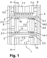
- the FIG. 1 shows a schematic representation of an electronic control cabinet 1, in which different modules 7.1, 7.2, 7.3 are arranged. These are modules 7 with a housing of the type, as exemplified in FIG. 3 is shown.
- the modules can be arranged as modules 7.1 with intensive cooling, as modules 7.2 with low cooling and / or as modules 7.3 without cooling.
- the modules 7.1, 7.2, 7.3 are arranged with their housing detachable on a mounting option, a DIN rail 8 and can be interconnected. Due to the detachable arrangement of the modules 7.1.7.2,7.3 on the top hat rail 8 is the possibility for a different task, the modules 7.1,7.2,7.3 differently in the electronic cabinet 1 to order or in addition to assemble.
- the cooling in the electronic cabinet 1 with little effort is changeable.
- vertical and horizontal channels 2.1, 2.2, 2.3, 2.4 are arranged, in which an air flow with cold air 5 is supplied through a vertical channel 2.2 and an air stream with hot air 6 is discharged via a vertical channel 2.4.
- a partition wall 3 for separating the air flow of warm air 6 and cold air 5 is arranged between the horizontal channels 2.1, 2.3.
- the air flow 5,6 takes the following route through the device.
- the cold air flow 5 enters the device, flows upwards and enters the horizontal channels 2.1 arranged in several planes, which are located below the housings of the modules 7.1, 7.2 of the module rows.
- the resulting hot air stream 6 leaves the housing of the modules 7.1.7.2 through the outlet openings 15.2 on the housing of the modules (in Fig. 1 not shown) and passes with or without air guide coupling 10 through the opening 14.2 for the air inlet into the horizontal channel 2.3 for the warm air.
- the hot air stream 6 passes through the horizontal channel 2.3 to the right in the vertical channel 2.4 for hot air flows upwards and can then leave the device.
- the modules 7.1 which require intensive cooling, are connected to the horizontal channels 2.1 and 2.3 via forced cooling, d. H. between the horizontal channels 2.1 and 2.3 and the housing of the module 7.1 are air guide couplings 10 between the openings 14.1 for air outlet in the horizontal channel 2.1 and the inlet openings 15.1 arranged on the module housing through which the air flow of the cold air 5 the module 7.1 is supplied with intensive cooling and through the air duct couplings 10 between the openings 14.2 for air inlet in the horizontal channel 2.3 and the outlet openings 15.2 on the module housing, the air flow of the hot air 6 of the module 7.1 with intensive cooling the horizontal channel 2.3 is returned and via this to the collecting duct for hot air, the vertical channel for hot air 2.4 led.
- the air guide couplings 10 are not required, but only openings 14.1, 14.2 for the air outlet and for the air inlet from and into the horizontal channels 2.1, 2.3. These openings 14.1, 14.2 may be closable in the event that the modules are arranged at a different location 7.2 and cooling at the intended location is no longer required.
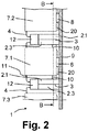
- FIG. 2 shows a schematic representation of an electronic control cabinet 1 in section AA of FIG. 1 , It can also be seen from this illustration how the DIN rails 8 are arranged on the mounting plate 9 of the electronic control cabinet 1. Furthermore, it is off FIG. 2 can be seen that in front of the horizontal cooling channels 2.1, 2.3 with the partition wall 3 of the cable channel 12 is disposed, lead from the cable 4, which are fixed by means of terminal 11 in the front part of the respective housing of the module 7.1, 7.2, 7.3.
- FIG. 3 shows an embodiment of a housing for the module 7, at the top and bottom of outlet and inlet openings 15.1, 15.2 are arranged, through which the air flow of cold and warm air 5, 6 can flow to the electronic assembly of the module 7 inside of the housing, which (not shown) in the central region 19 of the Module 7 is located in the housing. Depending on the intensity of the load, this electronic assembly represents the heat generation zone which is to be cooled.
- the snap connection 20 and the latching lug 16 are arranged, with which the housing of the module 7 is releasably attached to the DIN rail 8. The other side has a connection 13 for the cable 4 on the housing of the module 7.
- FIG. 4 shows the housing of the module in top view with the outlet opening 15.2 and the plug 17, with which the module 7 can be connected to the respective next module 7 and a, as in Fig. 1 represented, seamless module row can be formed.
Claims (10)
- Armoire électronique de commutation (1) pour centrale d'alerte incendie et/ou centrale de commande d'extinction, comprenant un boîtier doté d'une possibilité de fixation d'un module (7) dans un boîtier dans lequel des ensembles électroniques sont disposés,
des modules (7.1) à refroidissement intense, des modules (7.2) à refroidissement réduit et des modules (7.3) sans refroidissement pouvant être disposés dans le boîtier de l'armoire de commutation (1),
l'armoire de commutation (1) présentant en outre un dispositif de refroidissement pour les modules (7, 7.1, 7.2) à refroidir et présentant un premier et un deuxième canal (2.1, 2.3) essentiellement horizontaux entre deux premiers et deux deuxièmes canaux (2.2, 2.4) essentiellement verticaux,
chaque premier canal (2.1, 2.2) conduisant un écoulement d'air froid (5) vers les modules (7, 7.1, 7.2) à refroidir et chaque deuxième canal (2.3, 2.4) évacuant un écoulement d'air chaud (6) hors des modules (7, 7.1, 7.2) à refroidir,
les canaux horizontaux (2.1, 2.3) présentant des ouvertures (14.1, 14.2) pour les écoulements d'air chaud et d'air froid (5, 6) aux emplacements auxquels des modules (7, 7.1, 7.2) à refroidir sont disposés, caractérisé en ce que
pour les modules (7.1) qui reçoivent un refroidissement plus intense, des raccordements (10) de guidage d'air sont disposés entre les modules (7.1) et les premiers et les deuxièmes canaux (2.1, 2.3) horizontaux. - Ensemble selon la revendication 1, dans lequel les raccordements (10) de guidage d'air entre les canaux horizontaux (2.1, 2.3) et le boîtier des modules (7.1) présentent des raccordements (10) de guidage d'air entre les ouvertures (14.1) de sortie d'air dans le canal horizontal (2.1) et sur le boîtier de modules des ouvertures d'entrée (15.1) par lesquelles l'écoulement d'air froid (5) est amené aux modules (7.1) à refroidissement intense, et présentent entre les ouvertures (14.2) d'entrée d'air dans le canal horizontal (2.3) et les ouvertures de sortie (15.2) sur le boîtier de modules des raccordements (10) de guidage d'air par lesquels l'écoulement d'air chaud (6) provenant du module (7.1) à refroidissement intense est renvoyé dans le canal horizontal (2.3) et par ce dernier dans le canal de collecte d'air chaud et vers l'un des canaux verticaux d'air chaud (2.4).
- Ensemble selon la revendication 1 ou la revendication 2, caractérisé en ce que les canaux horizontaux (2.1, 2.3) sont formés par un canal à paroi de séparation (3).
- Ensemble selon l'une des revendications 1 à 3, caractérisé en ce que l'ensemble de refroidissement présente au moins un ventilateur.
- Ensemble selon l'une des revendications 1 à 4, caractérisé en ce que l'ensemble de refroidissement présente au moins un échangeur de chaleur.
- Ensemble selon l'une des revendications 1 à 5, caractérisé en ce que les ouvertures (14.1, 14.2) présentent des ensembles de fermeture.
- Ensemble selon l'une des revendications 1 à 6, caractérisé en ce que des dispositifs d'amenée d'air froid ou d'air chaud (5, 6) sont disposés entre les ouvertures (14.1, 14.2) et le module (7.1).
- Ensemble selon la revendication 7, caractérisé en ce que les dispositifs disposés entre les modules (7.1) et les ouvertures (14.1, 14.2) sont des raccordements (10) de guidage d'air de forme circulaire, semi-circulaire, ovale, polygonale, rectangulaire ou en U.
- Ensemble selon l'une des revendications 1 à 8, caractérisé en ce qu'un canal (12) pour câble est disposé sur ou dans le canal d'air horizontal.
- Ensemble selon la revendication 9, caractérisé en ce que le canal d'air horizontal (12) est disposé en amont du canal d'air horizontal et en ce qu'un câble (4) provenant du canal (12) pour câble conduit jusque dans la partie avant du module (7, 7.1, 7.2, 7.3).
Priority Applications (3)
| Application Number | Priority Date | Filing Date | Title |
|---|---|---|---|
| EP12198984.2A EP2747533B1 (fr) | 2012-12-21 | 2012-12-21 | Armoire électrique électronique avec refroidissement |
| US14/134,059 US20140177170A1 (en) | 2012-12-21 | 2013-12-19 | Electronic Control Cabinet with Cooling |
| CN201310710931.6A CN103887720A (zh) | 2012-12-21 | 2013-12-20 | 带有冷却装置的电子开关柜 |
Applications Claiming Priority (1)
| Application Number | Priority Date | Filing Date | Title |
|---|---|---|---|
| EP12198984.2A EP2747533B1 (fr) | 2012-12-21 | 2012-12-21 | Armoire électrique électronique avec refroidissement |
Publications (2)
| Publication Number | Publication Date |
|---|---|
| EP2747533A1 EP2747533A1 (fr) | 2014-06-25 |
| EP2747533B1 true EP2747533B1 (fr) | 2017-11-29 |
Family
ID=47709767
Family Applications (1)
| Application Number | Title | Priority Date | Filing Date |
|---|---|---|---|
| EP12198984.2A Not-in-force EP2747533B1 (fr) | 2012-12-21 | 2012-12-21 | Armoire électrique électronique avec refroidissement |
Country Status (3)
| Country | Link |
|---|---|
| US (1) | US20140177170A1 (fr) |
| EP (1) | EP2747533B1 (fr) |
| CN (1) | CN103887720A (fr) |
Families Citing this family (6)
| Publication number | Priority date | Publication date | Assignee | Title |
|---|---|---|---|---|
| CN105612822B (zh) | 2013-09-26 | 2019-05-31 | Abb瑞士股份有限公司 | 轨道安装的控制系统 |
| DE102014101453A1 (de) * | 2014-02-06 | 2015-08-06 | R. Stahl Schaltgeräte GmbH | Schaltschrank mit Klimatisierungsvorrichtung |
| DE102014104857A1 (de) * | 2014-04-04 | 2015-10-08 | Armin Meininger | Vorrichtung zur Klimatisierung elektronischer Baugruppen |
| DE102014017658A1 (de) * | 2014-11-24 | 2016-05-25 | Friedrich Lütze GmbH | Klimatisierungsanordnung |
| CN208462236U (zh) * | 2015-03-02 | 2019-02-01 | Abb瑞士股份有限公司 | 控制系统 |
| CN206211354U (zh) * | 2016-06-01 | 2017-05-31 | 林楚萍 | 一种自动化控制的散热式电气柜 |
Family Cites Families (29)
| Publication number | Priority date | Publication date | Assignee | Title |
|---|---|---|---|---|
| DE2211268C3 (de) * | 1972-03-09 | 1978-10-12 | Licentia Patent-Verwaltungs-Gmbh, 6000 Frankfurt | Lüftungsanordnung für Einschübe |
| DE2638118B2 (de) | 1976-08-25 | 1978-09-07 | Licentia Patent-Verwaltungs-Gmbh, 6000 Frankfurt | Belüftungsmodul für einen Elektronikschrank |
| US4277815A (en) * | 1979-06-15 | 1981-07-07 | Westinghouse Electric Corp. | Replaceable air seal for force cooled removable electronic units |
| DE4035213C2 (de) | 1990-11-06 | 1995-01-26 | Vero Electronics Gmbh | Gehäuse mit Kühleinrichtung |
| JPH07202464A (ja) * | 1993-12-28 | 1995-08-04 | Toshiba Corp | 電子機器装置並びに電子機器装置用冷却方法及びファン装置 |
| JP3323881B2 (ja) * | 1997-05-28 | 2002-09-09 | シャープ株式会社 | 薄型ケーブルモデム及びその載置用スタンド |
| FI108962B (fi) * | 1999-08-20 | 2002-04-30 | Nokia Corp | Laitekaapin jäähdytysjärjestelmä |
| US6557357B2 (en) * | 2000-02-18 | 2003-05-06 | Toc Technology, Llc | Computer rack heat extraction device |
| US6592449B2 (en) * | 2001-02-24 | 2003-07-15 | International Business Machines Corporation | Smart fan modules and system |
| US6459577B1 (en) * | 2001-07-06 | 2002-10-01 | Apple Computer, Inc. | Thermal chimney for a computer |
| US6889752B2 (en) * | 2002-07-11 | 2005-05-10 | Avaya Technology Corp. | Systems and methods for weatherproof cabinets with multiple compartment cooling |
| US6611428B1 (en) * | 2002-08-12 | 2003-08-26 | Motorola, Inc. | Cabinet for cooling electronic modules |
| DE50311081D1 (de) * | 2002-10-22 | 2009-03-05 | Eas Schaltanlagen Gmbh | Anordnung zur Erkennung einer Rauchentwicklung und/oder eines Brandes in einem Schaltschrank od. dgl. zwecks Auslösung eines Feueralarms und Betriebsverfahren für diese |
| US7500911B2 (en) * | 2002-11-25 | 2009-03-10 | American Power Conversion Corporation | Exhaust air removal system |
| US7112131B2 (en) * | 2003-05-13 | 2006-09-26 | American Power Conversion Corporation | Rack enclosure |
| US6819563B1 (en) * | 2003-07-02 | 2004-11-16 | International Business Machines Corporation | Method and system for cooling electronics racks using pre-cooled air |
| DE102004030785B3 (de) * | 2004-03-15 | 2005-11-10 | Pfannenberg Gmbh | Kühlanordnung für einen Schaltschrank mit Kühlgerät zum Einsatz in explosionsgefährdeten Räumen |
| US7104081B2 (en) * | 2004-03-30 | 2006-09-12 | International Business Machines Corproation | Condensate removal system and method for facilitating cooling of an electronics system |
| DE202004006552U1 (de) * | 2004-04-26 | 2004-07-08 | Knürr AG | Kühlungssystem für Geräte- und Netzwerkschränke |
| US8944896B2 (en) * | 2007-02-22 | 2015-02-03 | Tellabs Operations, Inc. | Apparatus, system, and method for venting a chassis |
| EP2073618B1 (fr) * | 2007-12-17 | 2011-01-26 | Siemens Aktiengesellschaft | Appareil électronique |
| CN101299571B (zh) * | 2008-03-14 | 2011-05-11 | 北京合康亿盛变频科技股份有限公司 | 用于高压变频设备的循环冷风装置 |
| JP4951596B2 (ja) * | 2008-07-31 | 2012-06-13 | 株式会社日立製作所 | 冷却システム及び電子装置 |
| DE102009043455A1 (de) * | 2009-09-29 | 2011-04-07 | Siemens Aktiengesellschaft | Anordnung zum Installieren von Geräten der Gebäudesystemtechnik |
| DE102010002295A1 (de) * | 2010-02-24 | 2011-08-25 | Liebold, Edgar, 08064 | Brandmelder sowie Überwachungssystem mit einem solchen Brandmelder |
| US8248793B2 (en) * | 2010-03-29 | 2012-08-21 | Hewlett-Packard Development Company, L.P. | Electronic component having a movable louver |
| EP2479861B1 (fr) * | 2011-01-19 | 2016-12-14 | Siemens Aktiengesellschaft | Appareil d'automatisation |
| US8743549B2 (en) * | 2011-03-22 | 2014-06-03 | Amazon Technologies, Inc. | Modular mass storage system |
| CN102186329B (zh) * | 2011-05-04 | 2013-06-19 | 中航光电科技股份有限公司 | 一种用于电子设备的冷却装置 |
-
2012
- 2012-12-21 EP EP12198984.2A patent/EP2747533B1/fr not_active Not-in-force
-
2013
- 2013-12-19 US US14/134,059 patent/US20140177170A1/en not_active Abandoned
- 2013-12-20 CN CN201310710931.6A patent/CN103887720A/zh active Pending
Non-Patent Citations (1)
| Title |
|---|
| None * |
Also Published As
| Publication number | Publication date |
|---|---|
| EP2747533A1 (fr) | 2014-06-25 |
| US20140177170A1 (en) | 2014-06-26 |
| CN103887720A (zh) | 2014-06-25 |
Similar Documents
| Publication | Publication Date | Title |
|---|---|---|
| EP2747533B1 (fr) | Armoire électrique électronique avec refroidissement | |
| EP0878991B1 (fr) | Ossature d'armoire support de baies avec dispositif de ventilation | |
| EP1614333B1 (fr) | Systeme de refroidissement pour armoires d'instruments et armoires reseau, et procede pour refroidir des armoires d'instruments et armoires reseau | |
| EP1967938A1 (fr) | Armoire électrique destinée à la réception de modules enfichables électroniques dotée d'un échangeur thermique | |
| EP1719044A2 (fr) | Ensemble de dispositifs | |
| EP1853101A1 (fr) | Support pour composants doté d'un boîtier destiné à la réception de modules enfichables | |
| DE102009054011B4 (de) | Kühlanordnung für in einem Schaltschrank angeordnete elektrische Geräte | |
| EP1895824B1 (fr) | Assemblage pour un appareil d'automatisation | |
| DE202009015124U1 (de) | Anordnung zum Kühlen von elektrischen und elektronischen Bauteilen und Moduleinheiten in Geräteschränken | |
| WO2016162014A1 (fr) | Ensemble d'armoires électriques avec une rangée d'armoires électriques et un appareil de refroidissement intégré dans la rangée | |
| DE102009057129A1 (de) | Belüftungsvorrichtung für Komponenten eines Elektronik- oder Computerschranks | |
| EP3066904A1 (fr) | Composant fonctionnel pour un système d'assemblage de composants | |
| DE3837029C2 (fr) | ||
| WO2018206030A1 (fr) | Système de dissipation de chaleur pour une armoire de commande | |
| DE102014201483B4 (de) | Quaderförmiges Gehäuse für ein Elektronikmodul, Elektronikmodul und Anordnung zur Kühlung wenigstens eines Elektronikmoduls | |
| DE202006013162U1 (de) | Vorrichtung mit Luft-Luft-Wärmetauscher zur Bereitstellung von Kühlluft für einen Elektroschrank | |
| DE3507255A1 (de) | Gehaeuse fuer elektrische bauteile | |
| DE2015361B2 (de) | Gestellanordnung fur elektrische oder elektronische Gerate | |
| DE10326355B3 (de) | Luftleiteinrichtung zum Kühlen eines Schalterteiles eines elektrischen Schalters | |
| DE3206868C2 (fr) | ||
| EP2801137A1 (fr) | Système de rails conducteurs spécialement pour de longs tronçons verticaux | |
| AT13912U1 (de) | Kabel-Schrank mit Tiefenerweiterung | |
| DE102013217446A1 (de) | Datenverarbeitungssystem | |
| DE4035212A1 (de) | Gehaeusesystem | |
| DE2740772B2 (de) | Einrichtung zur Abführung der Verlustwärme elektronischer Baugruppen |
Legal Events
| Date | Code | Title | Description |
|---|---|---|---|
| PUAI | Public reference made under article 153(3) epc to a published international application that has entered the european phase |
Free format text: ORIGINAL CODE: 0009012 |
|
| 17P | Request for examination filed |
Effective date: 20121221 |
|
| AK | Designated contracting states |
Kind code of ref document: A1 Designated state(s): AL AT BE BG CH CY CZ DE DK EE ES FI FR GB GR HR HU IE IS IT LI LT LU LV MC MK MT NL NO PL PT RO RS SE SI SK SM TR |
|
| AX | Request for extension of the european patent |
Extension state: BA ME |
|
| R17P | Request for examination filed (corrected) |
Effective date: 20150105 |
|
| RBV | Designated contracting states (corrected) |
Designated state(s): AL AT BE BG CH CY CZ DE DK EE ES FI FR GB GR HR HU IE IS IT LI LT LU LV MC MK MT NL NO PL PT RO RS SE SI SK SM TR |
|
| 17Q | First examination report despatched |
Effective date: 20170203 |
|
| GRAP | Despatch of communication of intention to grant a patent |
Free format text: ORIGINAL CODE: EPIDOSNIGR1 |
|
| INTG | Intention to grant announced |
Effective date: 20170912 |
|
| GRAS | Grant fee paid |
Free format text: ORIGINAL CODE: EPIDOSNIGR3 |
|
| GRAA | (expected) grant |
Free format text: ORIGINAL CODE: 0009210 |
|
| AK | Designated contracting states |
Kind code of ref document: B1 Designated state(s): AL AT BE BG CH CY CZ DE DK EE ES FI FR GB GR HR HU IE IS IT LI LT LU LV MC MK MT NL NO PL PT RO RS SE SI SK SM TR |
|
| REG | Reference to a national code |
Ref country code: CH Ref legal event code: EP |
|
| REG | Reference to a national code |
Ref country code: AT Ref legal event code: REF Ref document number: 951472 Country of ref document: AT Kind code of ref document: T Effective date: 20171215 |
|
| REG | Reference to a national code |
Ref country code: IE Ref legal event code: FG4D Free format text: LANGUAGE OF EP DOCUMENT: GERMAN |
|
| REG | Reference to a national code |
Ref country code: FR Ref legal event code: PLFP Year of fee payment: 6 |
|
| REG | Reference to a national code |
Ref country code: DE Ref legal event code: R096 Ref document number: 502012011727 Country of ref document: DE |
|
| REG | Reference to a national code |
Ref country code: NL Ref legal event code: FP |
|
| REG | Reference to a national code |
Ref country code: LT Ref legal event code: MG4D |
|
| PG25 | Lapsed in a contracting state [announced via postgrant information from national office to epo] |
Ref country code: SE Free format text: LAPSE BECAUSE OF FAILURE TO SUBMIT A TRANSLATION OF THE DESCRIPTION OR TO PAY THE FEE WITHIN THE PRESCRIBED TIME-LIMIT Effective date: 20171129 Ref country code: LT Free format text: LAPSE BECAUSE OF FAILURE TO SUBMIT A TRANSLATION OF THE DESCRIPTION OR TO PAY THE FEE WITHIN THE PRESCRIBED TIME-LIMIT Effective date: 20171129 Ref country code: FI Free format text: LAPSE BECAUSE OF FAILURE TO SUBMIT A TRANSLATION OF THE DESCRIPTION OR TO PAY THE FEE WITHIN THE PRESCRIBED TIME-LIMIT Effective date: 20171129 Ref country code: ES Free format text: LAPSE BECAUSE OF FAILURE TO SUBMIT A TRANSLATION OF THE DESCRIPTION OR TO PAY THE FEE WITHIN THE PRESCRIBED TIME-LIMIT Effective date: 20171129 Ref country code: NO Free format text: LAPSE BECAUSE OF FAILURE TO SUBMIT A TRANSLATION OF THE DESCRIPTION OR TO PAY THE FEE WITHIN THE PRESCRIBED TIME-LIMIT Effective date: 20180228 |
|
| PG25 | Lapsed in a contracting state [announced via postgrant information from national office to epo] |
Ref country code: HR Free format text: LAPSE BECAUSE OF FAILURE TO SUBMIT A TRANSLATION OF THE DESCRIPTION OR TO PAY THE FEE WITHIN THE PRESCRIBED TIME-LIMIT Effective date: 20171129 Ref country code: LV Free format text: LAPSE BECAUSE OF FAILURE TO SUBMIT A TRANSLATION OF THE DESCRIPTION OR TO PAY THE FEE WITHIN THE PRESCRIBED TIME-LIMIT Effective date: 20171129 Ref country code: RS Free format text: LAPSE BECAUSE OF FAILURE TO SUBMIT A TRANSLATION OF THE DESCRIPTION OR TO PAY THE FEE WITHIN THE PRESCRIBED TIME-LIMIT Effective date: 20171129 Ref country code: GR Free format text: LAPSE BECAUSE OF FAILURE TO SUBMIT A TRANSLATION OF THE DESCRIPTION OR TO PAY THE FEE WITHIN THE PRESCRIBED TIME-LIMIT Effective date: 20180301 Ref country code: BG Free format text: LAPSE BECAUSE OF FAILURE TO SUBMIT A TRANSLATION OF THE DESCRIPTION OR TO PAY THE FEE WITHIN THE PRESCRIBED TIME-LIMIT Effective date: 20180228 |
|
| PG25 | Lapsed in a contracting state [announced via postgrant information from national office to epo] |
Ref country code: CY Free format text: LAPSE BECAUSE OF FAILURE TO SUBMIT A TRANSLATION OF THE DESCRIPTION OR TO PAY THE FEE WITHIN THE PRESCRIBED TIME-LIMIT Effective date: 20171129 Ref country code: CZ Free format text: LAPSE BECAUSE OF FAILURE TO SUBMIT A TRANSLATION OF THE DESCRIPTION OR TO PAY THE FEE WITHIN THE PRESCRIBED TIME-LIMIT Effective date: 20171129 Ref country code: EE Free format text: LAPSE BECAUSE OF FAILURE TO SUBMIT A TRANSLATION OF THE DESCRIPTION OR TO PAY THE FEE WITHIN THE PRESCRIBED TIME-LIMIT Effective date: 20171129 Ref country code: SK Free format text: LAPSE BECAUSE OF FAILURE TO SUBMIT A TRANSLATION OF THE DESCRIPTION OR TO PAY THE FEE WITHIN THE PRESCRIBED TIME-LIMIT Effective date: 20171129 Ref country code: DK Free format text: LAPSE BECAUSE OF FAILURE TO SUBMIT A TRANSLATION OF THE DESCRIPTION OR TO PAY THE FEE WITHIN THE PRESCRIBED TIME-LIMIT Effective date: 20171129 |
|
| REG | Reference to a national code |
Ref country code: DE Ref legal event code: R097 Ref document number: 502012011727 Country of ref document: DE |
|
| PG25 | Lapsed in a contracting state [announced via postgrant information from national office to epo] |
Ref country code: IT Free format text: LAPSE BECAUSE OF FAILURE TO SUBMIT A TRANSLATION OF THE DESCRIPTION OR TO PAY THE FEE WITHIN THE PRESCRIBED TIME-LIMIT Effective date: 20171129 Ref country code: RO Free format text: LAPSE BECAUSE OF FAILURE TO SUBMIT A TRANSLATION OF THE DESCRIPTION OR TO PAY THE FEE WITHIN THE PRESCRIBED TIME-LIMIT Effective date: 20171129 Ref country code: SM Free format text: LAPSE BECAUSE OF FAILURE TO SUBMIT A TRANSLATION OF THE DESCRIPTION OR TO PAY THE FEE WITHIN THE PRESCRIBED TIME-LIMIT Effective date: 20171129 Ref country code: PL Free format text: LAPSE BECAUSE OF FAILURE TO SUBMIT A TRANSLATION OF THE DESCRIPTION OR TO PAY THE FEE WITHIN THE PRESCRIBED TIME-LIMIT Effective date: 20171129 |
|
| REG | Reference to a national code |
Ref country code: IE Ref legal event code: MM4A |
|
| PG25 | Lapsed in a contracting state [announced via postgrant information from national office to epo] |
Ref country code: MT Free format text: LAPSE BECAUSE OF FAILURE TO SUBMIT A TRANSLATION OF THE DESCRIPTION OR TO PAY THE FEE WITHIN THE PRESCRIBED TIME-LIMIT Effective date: 20171129 Ref country code: LU Free format text: LAPSE BECAUSE OF NON-PAYMENT OF DUE FEES Effective date: 20171221 |
|
| PLBE | No opposition filed within time limit |
Free format text: ORIGINAL CODE: 0009261 |
|
| STAA | Information on the status of an ep patent application or granted ep patent |
Free format text: STATUS: NO OPPOSITION FILED WITHIN TIME LIMIT |
|
| REG | Reference to a national code |
Ref country code: BE Ref legal event code: MM Effective date: 20171231 |
|
| PG25 | Lapsed in a contracting state [announced via postgrant information from national office to epo] |
Ref country code: IE Free format text: LAPSE BECAUSE OF NON-PAYMENT OF DUE FEES Effective date: 20171221 |
|
| 26N | No opposition filed |
Effective date: 20180830 |
|
| PG25 | Lapsed in a contracting state [announced via postgrant information from national office to epo] |
Ref country code: BE Free format text: LAPSE BECAUSE OF NON-PAYMENT OF DUE FEES Effective date: 20171231 Ref country code: SI Free format text: LAPSE BECAUSE OF FAILURE TO SUBMIT A TRANSLATION OF THE DESCRIPTION OR TO PAY THE FEE WITHIN THE PRESCRIBED TIME-LIMIT Effective date: 20171129 |
|
| PG25 | Lapsed in a contracting state [announced via postgrant information from national office to epo] |
Ref country code: MC Free format text: LAPSE BECAUSE OF FAILURE TO SUBMIT A TRANSLATION OF THE DESCRIPTION OR TO PAY THE FEE WITHIN THE PRESCRIBED TIME-LIMIT Effective date: 20171129 Ref country code: HU Free format text: LAPSE BECAUSE OF FAILURE TO SUBMIT A TRANSLATION OF THE DESCRIPTION OR TO PAY THE FEE WITHIN THE PRESCRIBED TIME-LIMIT; INVALID AB INITIO Effective date: 20121221 |
|
| PG25 | Lapsed in a contracting state [announced via postgrant information from national office to epo] |
Ref country code: MK Free format text: LAPSE BECAUSE OF FAILURE TO SUBMIT A TRANSLATION OF THE DESCRIPTION OR TO PAY THE FEE WITHIN THE PRESCRIBED TIME-LIMIT Effective date: 20171129 |
|
| PGFP | Annual fee paid to national office [announced via postgrant information from national office to epo] |
Ref country code: NL Payment date: 20191217 Year of fee payment: 8 |
|
| PG25 | Lapsed in a contracting state [announced via postgrant information from national office to epo] |
Ref country code: TR Free format text: LAPSE BECAUSE OF FAILURE TO SUBMIT A TRANSLATION OF THE DESCRIPTION OR TO PAY THE FEE WITHIN THE PRESCRIBED TIME-LIMIT Effective date: 20171129 |
|
| PGFP | Annual fee paid to national office [announced via postgrant information from national office to epo] |
Ref country code: CH Payment date: 20191220 Year of fee payment: 8 Ref country code: AT Payment date: 20191213 Year of fee payment: 8 |
|
| PG25 | Lapsed in a contracting state [announced via postgrant information from national office to epo] |
Ref country code: PT Free format text: LAPSE BECAUSE OF FAILURE TO SUBMIT A TRANSLATION OF THE DESCRIPTION OR TO PAY THE FEE WITHIN THE PRESCRIBED TIME-LIMIT Effective date: 20171129 |
|
| PG25 | Lapsed in a contracting state [announced via postgrant information from national office to epo] |
Ref country code: IS Free format text: LAPSE BECAUSE OF FAILURE TO SUBMIT A TRANSLATION OF THE DESCRIPTION OR TO PAY THE FEE WITHIN THE PRESCRIBED TIME-LIMIT Effective date: 20180329 Ref country code: AL Free format text: LAPSE BECAUSE OF FAILURE TO SUBMIT A TRANSLATION OF THE DESCRIPTION OR TO PAY THE FEE WITHIN THE PRESCRIBED TIME-LIMIT Effective date: 20171129 |
|
| REG | Reference to a national code |
Ref country code: CH Ref legal event code: PL |
|
| REG | Reference to a national code |
Ref country code: NL Ref legal event code: MM Effective date: 20210101 |
|
| REG | Reference to a national code |
Ref country code: AT Ref legal event code: MM01 Ref document number: 951472 Country of ref document: AT Kind code of ref document: T Effective date: 20201221 |
|
| PG25 | Lapsed in a contracting state [announced via postgrant information from national office to epo] |
Ref country code: NL Free format text: LAPSE BECAUSE OF NON-PAYMENT OF DUE FEES Effective date: 20210101 |
|
| PG25 | Lapsed in a contracting state [announced via postgrant information from national office to epo] |
Ref country code: AT Free format text: LAPSE BECAUSE OF NON-PAYMENT OF DUE FEES Effective date: 20201221 |
|
| PG25 | Lapsed in a contracting state [announced via postgrant information from national office to epo] |
Ref country code: LI Free format text: LAPSE BECAUSE OF NON-PAYMENT OF DUE FEES Effective date: 20201231 Ref country code: CH Free format text: LAPSE BECAUSE OF NON-PAYMENT OF DUE FEES Effective date: 20201231 |
|
| REG | Reference to a national code |
Ref country code: DE Ref legal event code: R081 Ref document number: 502012011727 Country of ref document: DE Owner name: MINIMAX GMBH, DE Free format text: FORMER OWNER: MINIMAX GMBH & CO. KG, 23843 BAD OLDESLOE, DE |
|
| PGFP | Annual fee paid to national office [announced via postgrant information from national office to epo] |
Ref country code: FR Payment date: 20211220 Year of fee payment: 10 Ref country code: GB Payment date: 20211222 Year of fee payment: 10 |
|
| PGFP | Annual fee paid to national office [announced via postgrant information from national office to epo] |
Ref country code: DE Payment date: 20211220 Year of fee payment: 10 |
|
| REG | Reference to a national code |
Ref country code: DE Ref legal event code: R119 Ref document number: 502012011727 Country of ref document: DE |
|
| GBPC | Gb: european patent ceased through non-payment of renewal fee |
Effective date: 20221221 |
|
| PG25 | Lapsed in a contracting state [announced via postgrant information from national office to epo] |
Ref country code: GB Free format text: LAPSE BECAUSE OF NON-PAYMENT OF DUE FEES Effective date: 20221221 Ref country code: DE Free format text: LAPSE BECAUSE OF NON-PAYMENT OF DUE FEES Effective date: 20230701 |
|
| PG25 | Lapsed in a contracting state [announced via postgrant information from national office to epo] |
Ref country code: FR Free format text: LAPSE BECAUSE OF NON-PAYMENT OF DUE FEES Effective date: 20221231 |