EP2747034B1 - Correction de localisation d'objets virtuels - Google Patents
Correction de localisation d'objets virtuels Download PDFInfo
- Publication number
- EP2747034B1 EP2747034B1 EP13198217.5A EP13198217A EP2747034B1 EP 2747034 B1 EP2747034 B1 EP 2747034B1 EP 13198217 A EP13198217 A EP 13198217A EP 2747034 B1 EP2747034 B1 EP 2747034B1
- Authority
- EP
- European Patent Office
- Prior art keywords
- virtual
- real
- world
- computer
- virtual model
- Prior art date
- Legal status (The legal status is an assumption and is not a legal conclusion. Google has not performed a legal analysis and makes no representation as to the accuracy of the status listed.)
- Active
Links
- 238000012937 correction Methods 0.000 title claims description 27
- 238000000034 method Methods 0.000 claims description 39
- 238000004088 simulation Methods 0.000 claims description 15
- 238000004590 computer program Methods 0.000 claims description 6
- 230000008569 process Effects 0.000 description 14
- 238000004519 manufacturing process Methods 0.000 description 8
- 230000006870 function Effects 0.000 description 5
- 238000010586 diagram Methods 0.000 description 4
- 238000013519 translation Methods 0.000 description 4
- 230000014616 translation Effects 0.000 description 4
- 238000013459 approach Methods 0.000 description 3
- 238000004891 communication Methods 0.000 description 3
- 238000005259 measurement Methods 0.000 description 3
- 238000012986 modification Methods 0.000 description 3
- 230000004048 modification Effects 0.000 description 3
- 238000004364 calculation method Methods 0.000 description 2
- 230000001413 cellular effect Effects 0.000 description 2
- 238000012417 linear regression Methods 0.000 description 2
- 238000012545 processing Methods 0.000 description 2
- 230000003190 augmentative effect Effects 0.000 description 1
- 239000002772 conduction electron Substances 0.000 description 1
- 230000001419 dependent effect Effects 0.000 description 1
- 238000013461 design Methods 0.000 description 1
- 238000005516 engineering process Methods 0.000 description 1
- 239000004973 liquid crystal related substance Substances 0.000 description 1
- 239000003550 marker Substances 0.000 description 1
- 230000007246 mechanism Effects 0.000 description 1
- 230000001404 mediated effect Effects 0.000 description 1
- 230000003287 optical effect Effects 0.000 description 1
- 230000008520 organization Effects 0.000 description 1
- 238000003909 pattern recognition Methods 0.000 description 1
- 229920000642 polymer Polymers 0.000 description 1
- 230000009467 reduction Effects 0.000 description 1
- 238000007634 remodeling Methods 0.000 description 1
- 238000009877 rendering Methods 0.000 description 1
- 239000004065 semiconductor Substances 0.000 description 1
- 230000003068 static effect Effects 0.000 description 1
- 230000002123 temporal effect Effects 0.000 description 1
- 230000007723 transport mechanism Effects 0.000 description 1
Images


Classifications
-
- G—PHYSICS
- G06—COMPUTING; CALCULATING OR COUNTING
- G06T—IMAGE DATA PROCESSING OR GENERATION, IN GENERAL
- G06T19/00—Manipulating 3D models or images for computer graphics
- G06T19/20—Editing of 3D images, e.g. changing shapes or colours, aligning objects or positioning parts
-
- G—PHYSICS
- G06—COMPUTING; CALCULATING OR COUNTING
- G06T—IMAGE DATA PROCESSING OR GENERATION, IN GENERAL
- G06T17/00—Three dimensional [3D] modelling, e.g. data description of 3D objects
-
- G—PHYSICS
- G06—COMPUTING; CALCULATING OR COUNTING
- G06T—IMAGE DATA PROCESSING OR GENERATION, IN GENERAL
- G06T2219/00—Indexing scheme for manipulating 3D models or images for computer graphics
- G06T2219/20—Indexing scheme for editing of 3D models
- G06T2219/2016—Rotation, translation, scaling
Definitions
- the embodiments described herein relate generally to graphical representations of real-world objects and/or scenes and, more particularly, to three-dimensional (3D) computer graphic modeling and simulation, and layout and location calibration of virtual objects that represent real-world objects.
- Location of an object consists of both position and orientation of the object.
- Three-dimensional computer graphic simulations of manufacturing workcells are currently used for simulating manufacturing processes.
- the programs or simulation models are then downloaded to computers on the factory floor to drive the resources such as industrial robots.
- a virtual 3D model of the manufacturing workcell (including the machines, fixtures, and work pieces used in a manufacturing process) need to be adjusted for layout in the simulated workcell to match the actual position and orientations in the real workcell on the factory floor.
- This is enables the simulated manufacturing programs to validate the process for issues such as reachability and collisions.
- This also enables correct operation of the offline programs that will be downloaded to the manufacturing resources such as industrial robots in the factory.
- Hervé et al. describe in "Dynamic registration for Augmented Reality in Telerobotics Applications", IEEE International Conference on Sytems, Man, and Cybernetics, 8-11 October 2000 , the alignment of a virtual camera used to render the virtual replica of a robot manipulator with the real camera providing images from the work site.
- a computer-implemented method as defined by independent claim 1 for use in location correction of a virtual model of a real-world scene.
- the method includes generating the virtual model, including multiple virtual objects and a same virtual reference object, the multiple virtual objects and the virtual reference object each having a respective location in the virtual model; for each virtual object: acquiring at least one digital image including representations of a real-world object and a real-world reference object within the real-world scene along with a corresponding virtual view of the virtual model, wherein the real-world object corresponds to the virtual object and the real-world reference object corresponds to the virtual reference object; adjusting the virtual view by automatically aligning the virtual reference object in the virtual model with the representation of the real-world reference object in the real-world scene in the acquired at least one digital image; by a processor, calculating an image-based positional difference between at least one predefined point on the virtual object in the adjusted virtual view and at least one corresponding point on the real-world object in the acquired at least one digital image; adjusting at least one
- a computer for use in location correction of a virtual model of a real-world scene, as defined by independent claim 8.
- Exemplary embodiments of computer-implemented methods, computer devices and systems, and computer program products for use in location correction of a virtual model of a real-world scene are described herein.
- the embodiments described herein facilitate 3D location correction for virtual objects in computer graphic models using, for example, a handheld tablet computer with a built-in digital camera, 3D graphical simulation or virtual reality software, and a method to achieve the desired spatial calibration.
- the embodiments described herein exploit the combination of high resolution photographic and computation capability built into such handheld tablet computers, along with the mathematically rigorous rendering of 3D model images from the software.
- the approach involves a type of "mediated reality," with the user capturing a small set of digital camera static images of the workcell superimposed on top of a 3D virtual image of the workcell model on the tablet computer.
- the embodiments described herein do not require superimposing an image over a virtual model.
- the embodiments described herein also enable a computer device to display the image and the virtual modelin a side-by-side manner, for example, such that positional calculations and movements are tracked separately in each application.
- the computation approach detailed below then adjusts the 3D locations of the virtual objects in the virtual model to solve the calibration problem.
- the embodiments described herein facilitate ease of use, speed of the procedure, and a substantial reduction in cost and setup time for the measurement and equipment.
- the embodiments described herein contain an approach that eliminates the need for hardware-specific customization or length-standard type calibration of the digital camera built into the tablet computer during the 3D location adjustment.
- the embodiments described herein are scalable from small to large dimensions of the objects as well as fine to coarse accuracy of the adjustments as explained in detail below.
- the embodiments described herein are explained in relation to industrial and/or manufacturing resources, the embodiments are not limited to such uses.
- the embodiments may also be used during interior design for remodeling a room interior, wherein the 3D graphic model of the layout of existing objects such as furniture could be adjusted to correctly match the real layout inside the building room before commencing the redesign.
- Another example is architecture, wherein a 3D model of a set of buildings approximately located in the virtual model could be adjusted for actual positions by taking the tablet computer outdoors and capturing digital images of the buildings while walking around the grounds.
- Figure 1 is a schematic block diagram of an exemplary computer system 100 for use in location correction of a virtual model of a real-world scene, and/or for use in performing the processes described below and/or additional processes that may be related to those described below.
- a memory area 102 includes one or more storage devices 104 for use in storing data, such as data related to simulations of real-world scenes.
- the storage devices 104 may be embodied as one or more databases and/or may be located at a single or at multiple geographical sites.
- the memory area 102 is coupled to a server system 106. In an alternative embodiment, the memory area 102 is integrated with the server system 106.
- the server system 106 is coupled to one or more client devices 108 via a network 110.
- Client devices 108 may include mobile client devices including, but not limited to only including, laptop computers, tablet computers, and/or smartphones.
- client devices 108 may include stationary client devices that are generally not mobile, such as desktop computers and the like.
- the network 110 can be a public network, such as the Internet, or a private network such as an LAN or WAN network, or any combination thereof and can also include PSTN or ISDN sub-networks.
- the network 110 can also be wired, such as an Ethernet network, or can be wireless such as a cellular network including EDGE, 3G, and 4G or LTE wireless cellular systems.
- the wireless network can also be WiFi, Bluetooth, or any other wireless form of communication that is known.
- the network 110 is merely exemplary and in no way limits the scope of the present advancements.
- the server system 106 and/or the client devices 108 can be any suitable computer architecture such as the one described below with reference to Figure 5 , or any other computing architecture that is known. Moreover, it should be understood that the server system 106 is configured to perform the processes described above and/or any additional processes that may be related to those described above.
- the server system 106 can also provide data from the memory area 108 as needed to the client devices 108 such that the client devices 108 execute the processes described above.
- Figure 1 includes implementations of the computer system 100 via cloud computing, distributed computing, and the like.
- the server system 106 stores computer-readable instructions to execute the processes described below, and provides these instructions via the network 110 to the client devices 108.
- Such computer-readable instructions may be embodied as a computer program product having one or more non-transitory computer-readable storage media with computer-executable components for use in location correction of a virtual model of a real-world scene.
- the components include a generation component that causes a processor to generate the virtual model, including a virtual object, and an acquisition component that causes the processor to acquire at least one digital image of a real-world object within the real-world scene, wherein the real-world object corresponds to the virtual object.
- the components also include a correction component that causes the processor to calculate an image positional difference between at least one predefined point on the virtual object and at least one corresponding point on the real-world object, adjust the position and/or the orientation of the virtual object based on the image positional difference, and adjust the virtual model with respect to the corrected location of the virtual object.
- FIG. 2 is a flowchart 200 that illustrates operation of the computer system 100 shown in Figure 1 .
- the server system 106 transmits 202 a virtual model, such as a 3D model for use in a simulation or virtual display of the real-world scene, of the real-world scene or workcell to a client device 108 via the network 110.
- the client device 108 loads 204 the virtual model into a simulation or virtual reality software module and receives 206 from a user selection of one or more virtual objects whose spatial locations the user wishes to adjust.
- the client device 108 also receives 208 from the user selection of a reference object or reference point within the virtual model.
- the client device 108 displays 210 the digital camera image superimposed on the virtual 3D view or in a side-by-side manner with the virtual 3D view.
- the 3D view in the client device 108 is then adjusted 212 based on additional user input, by virtual rotations and translations, the display of the virtual model to a desired viewpoint in terms of zoom and orientation, so as to approximately match the 3D view to the superimposed camera image.
- a digital image along with the corresponding 3D virtual view is then acquired 214 by the client device 108 and saved to the client device 108 and/or the server 106.
- the user then holds the client device 108 in the real-world scene, such as a room layout, factory floor, or building grounds, and moves about 216 with the client device 108 so as to get a different perspective in the display of the digital camera image along with the virtual model 210.
- the user repeatedly adjusts 212 the display of the virtual 3D view and captures a new digital image along with its 3D view each time 214.
- the client device 108 and/or the server system 106 then invokes 218 a location correction functionality that uses the captured digital image(s) to identify the position and orientation of the virtual object compared to the real-world object to which it corresponds, as detailed below in flowchart 300.
- the client device 108 and/or the server system 106 completes the location correction function, which results in improved accuracy of location and orientation of the virtual object in the virtual model with respect to the real-world object in the real-world scene.
- a resulting manufacturing simulation or virtual display will be enhanced such that spatial and/or temporal errors will be reduced.
- the client device 108 transmits properties of the virtual object and/or virtual model, such as the new position and/or orientation of the virtual object, to the server system 106 for storage in memory area 102. In such embodiments, the stored data can be accessed later for subsequent simulations.
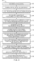
- FIG 3 is a flowchart 300 that further illustrates operation of the computer system 100 shown in Figure 1 .
- the server system 106 generates 302 a virtual model that represents a real-world scene.
- the server system 106 transmits 304 the virtual model to a client device 108 via the network 110.
- the client device 108 loads 306 the virtual model into a simulation or virtual reality software module.
- the client device 108 receives 308 user inputs to identify a virtual object and a reference object in the virtual model.
- the virtual object is one on which the user wishes to perform the location correction steps described herein.
- the reference object is one relative to which the location correction is completed.
- Figure 4A is an illustration of an exemplary display 400 of client device 108.
- the client device 108 displays a virtual object 402 and a reference object 404.
- the client device 108 also receives 310 user inputs to identify one or more predefined comparison features on the virtual object 402 and one or more corresponding comparison features on the reference object 404.
- vision processing and/or pattern recognition algorithms may be used to identify the predefined features on the virtual object 402 and the reference object 404.
- Figure 4A the 3D view of the virtual object 402 has three predefined features in the form of vertex points 406 and the reference object 404 has three corresponding predefined features in the form of vertex points 408.
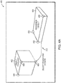
- Figure 4B is another illustration of display 400 of the client device 108 showing a digital image from the camera built-in to the client device.
- the real-world object 410 has three points 412 that correspond to the user-selected points 406 on the virtual object 402.
- the real-world reference object 414 has three points 416 that correspond to the user-selected points 408 on the virtual reference object 404.
- Figures 4A and 4B show the virtual object 402, virtual reference object 404, real-world object 410, and real-world reference object 414 as cubical objects, it will be understand that the embodiments described herein are not limited to use with cubical objects. Rather, the embodiments described herein may be used with objects of any shape that allows for selection of some identifiable set of points.
- the predefined comparison features 406, 408, 412, and/or 416 may be vertices, as shown in Figures 4A and 4B , or may be lines, planes, or surfaces.
- the client device 108 transmits data related to the identified points 406, 408, 412, and/or 416, such as coordinates of the identified points, to the server system 106.
- the client device 108 calculates 312 a location transform based on the identified points 406 and/or 408.
- the position and orientation of each virtual object is defined by six parameters (X, Y, Z, W, P, and R).
- the first three parameters (X, Y, Z) are distances that fix the position of the virtual object in an x-direction, a y-direction, and a z-direction.
- the second three parameters (W, P, R) are angles that fix the orientation of the virtual object, where W represents the yaw, P represents the pitch, and R represents the roll. Together, these six parameters can be called the location transform of the virtual object.
- the location transform of a virtual object 402 is calculated with respect to a reference coordinate system, such as that implied by the virtual reference object 404. Specifically, the location transform of the virtual object 402 is calculated based on the position (X, Y, Z) of the identified points 406 on the virtual object 402 and the identified points 408 on the reference object 404. As shown in Figure 4A , the points 406 on the virtual object 402 are those used to calculate the location transform 312.
- the reference object 404 provides both the reference coordinate system and a dimensional length standard for the location correction to be completed. Hence, the 3D model of the reference object 404 approximately matches a real-world reference object (not shown) in terms of the location of its identified points 408. In other words, the respective distances between the identified points 408 of the virtual reference object 404 and the corresponding points of the real-world reference object should be identical within an application dependant predefined tolerance.
- the camera device in the client device 108 acquires 314 digital images of the real world scenes along with their 3D virtual views as explained 210 to 214 in Figure2 .
- the client device 108 receives 212 user inputs in the form of manipulations of the virtual reference object 404.
- the user may use a touch screen to reposition, such as using rotate, translate, and/or zoom operations, such that the virtual object 402 and the reference object 404 is approximately aligned with the real-world object 410 and the reference object 414.
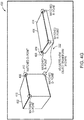
- Figures 4C and 4D are additional illustrations of display 400 of the client device 108.
- Figure 4C illustrates the client device 108 displaying the virtual model overlaid or simultaneously with the real-world scene, including the virtual object 402 and its corresponding real-world object 410, as well as the reference object 404 and its corresponding real-world reference object 414.
- the situation depicted in Figure 4C results after the user adjusts 212 the 3D virtual view to approximately align the real-world image.
- the client device 108 and/or the server 106 launches a programmatic adjustment 316 of the 3D virtual view by means of fine modifications of the viewing rotation, translation and/or zoom so as to approximately match the predefined points 408 on the reference object 404 with the points 416 on the real world reference object 414.
- This programmatic view adjustment is done for each of the images acquired 314 from different perspectives of the real-world scene.
- Figure 4D shows the resulting situation after step 316 such that the virtual reference object 404 matched up with the real-world reference object 414. Specifically, the points 408 of the reference object 404 are substantially aligned with corresponding points 416 of the real-world reference object 414.
- this programmatic adjustment 316 which eliminates the need for any hardware specific camera calibration and ensures that the length standard implied by the dimensions of the reference object 404 is automatically accounted for in the following location correction.
- the client device 108 and/or the server system 106 When the reference object 404 is substantially aligned by programmatic adjustment 316 with the real-world reference object 414, the client device 108 and/or the server system 106 now determines the mismatch between the virtual object points 406 and the corresponding points 412 on the real-world object 410. Specifically, the client device 108 and/or the server system 106 calculates 318 an image-based positional difference between the points 406 on the virtual object 402 and the corresponding points 412 on the real-world object 410. In an exemplary embodiment, the difference is calculated in pixels in each of the X and Y directions.
- Figure 4E is another illustration of display 400 of the client device 108.
- Figure 4E shows the distance in each of the X-direction (DeltaX) and in the Y-direction (DeltaY) for one of the points 406 of the virtual object 402 and a corresponding point 412 of the real-world object 410.
- the client device 108 and/or the server system 106 calculates 318 the difference for all pairs of identified points 406 and 412.
- the differences are stored in memory area 102.
- the client device 108 and/or the server system 106 calculates this image positional difference for each of the images acquired 314 from different perspectives of the real-world scene.
- Figure 4F is another illustration of a display of the client device 108.
- Figure 4F shows the image positional difference calculation for another capture from an alternate perspective of the real-world scene, after the reference object 404 has been substantially re-aligned with the real-world reference object 414.
- the client device 108 and/or the server system 106 then iterates 320 on the location transform of the virtual object 402 so as to minimize the combination of all the image positional differences between the virtual object 402 and the real-world object 410.
- the client device 108 and/or the server system 106 uses standard non-linear regression that minimizes a cost function by adjusting a set of variable parameters.
- the cost function is a summation of the root-mean-square (RMS) error for all of the calculated DeltaX and DeltaY differences.
- the variable parameters would be the (X, Y, Z, W, P, and R) values of the virtual object 402, i.e., the calculated location transform of the virtual object 402.
- Figure 4G is another illustration of the display of the client device 108. Specifically, Figure 4G shows the end result regarding the reorientation and/or repositioning of the virtual object 402 and the virtual model as a whole.
- the invention comprises adjusting the positions of multiple virtual objects, one or more at a time.
- each virtual model adjustment uses the same reference object.
- Figure 5 is a schematic block diagram of an exemplary computer architecture 500 for use with the server system 106 and/or the client devices 108 (each shown in Figure 1 ).
- the computer architecture 500 includes one or more processors 502 (CPU) that performs the processes described above and/or any additional processes that may be related to those described above.
- processors 502 refers generally to any programmable system including systems and microcontrollers, reduced instruction set circuits (RISC), application-specific integrated circuits (ASIC), programmable logic circuits, and/or any other circuit or processor capable of executing the functions described herein.
- RISC reduced instruction set circuits
- ASIC application-specific integrated circuits
- programmable logic circuits and/or any other circuit or processor capable of executing the functions described herein.
- the above examples are exemplary only and, thus, are not intended to limit in any way the definition and/or meaning of the term "processor.”
- a memory area 504 that is operably and/or communicatively coupled to the processor 502 by a system bus 506.
- a "memory area,” as used herein, refers generally to any means of storing non-transitory program code and instructions executable by one or more processors to aid in location correction of a virtual model of a real-world scene, and/or for use in performing the processes described above and/or additional processes that may be related to those described above.
- the memory area 504 may include one, or more than one, forms of memory.
- the memory area 504 may include random-access memory (RAM) 508, which can include non-volatile RAM, magnetic RAM, ferroelectric RAM, and/or other forms of RAM.
- RAM random-access memory
- the memory area 504 may also include read-only memory (ROM) 510 and/or flash memory and/or electrically-programmable read-only memory (EEPROM).
- ROM read-only memory
- EEPROM electrically-programmable read-only memory
- Any other suitable magnetic, optical, and/or semiconductor memory such as a hard-disk drive (HDD) 512, by itself or in combination with other forms of memory, may be included in the memory area 504.
- the HDD 512 may also be coupled to a disk controller 514 for use in transmitting and receiving messages to and from the processor 502.
- the memory area 504 may also be, or may include, a detachable or removable memory 516, such as a suitable cartridge disk, CD-ROM, DVD, or USB memory.
- a detachable or removable memory 516 such as a suitable cartridge disk, CD-ROM, DVD, or USB memory.
- the computer architecture 500 also includes a display device 518 that is coupled, such as operatively coupled, to a display controller 520.
- the display controller 520 receives data via the system bus 506 for display by the display device 518.
- the display device 518 may be, without limitation, a monitor, a television display, a plasma display, a liquid crystal display (LCD), a display based on light-emitting diodes (LED), a display based on organic LEDs (OLED), a display based on polymer LEDs, a display based on surface-conduction electron emitters, a display including a projected and/or reflected image, or any other suitable electronic device or display mechanism.
- the display device 518 may include a touchscreen 522 with an associated touchscreen controller 524. The above examples are exemplary only and, thus, are not intended to limit in any way the definition and/or meaning of the term "display device.”
- the computer architecture 500 includes a network interface 526 for use in communicating with a network (not shown in Figure 5 ).
- the computer architecture 500 includes one or more input devices, such as a keyboard 528 and/or a pointing device 530, such as a roller ball, mouse, touchpad, and the like.
- the touchscreen 522 and its controller 524 may also be thought of as integrated keyboard 528 and/or pointing device 530.
- the input devices are coupled to and controlled by an input/output (I/O) interface 532, which is further coupled to the system bus 506.
- the computer architecture 500 also includes at least one digital camera 534 with its associated digital camera controller 536.
- the processor 502 During operation, and referring to Figures 2-5 , the processor 502 generates a virtual model that represents a real-world scene and loads the virtual model into a simulation or virtual reality software module.
- the processor 502 receives user inputs via the touchscreen 522, for example, to identify a virtual object and a reference object in the virtual model.
- the virtual object is one on which the user wishes to perform the location correction steps described herein.
- the reference object is one against which the location correction is completed.
- the processor 502 also receives user inputs to identify one or more predefined points on the virtual object and one or more corresponding points on the reference object. After the predefined points are identified, the processor 502 calculates a location transform based on the identified points. Moreover, the location transform of a virtual object is calculated with respect to a reference point, such as the reference object. After the location transform is calculated, the camera device 534 acquires a digital image of a real-world object within the real-world scene, wherein the real-world object corresponds to the virtual object. Moreover, during image acquisition the processor 502 receives user inputs in the form of manipulations 3D virtual view.
- the user may use the touchscreen 522 to reposition, such as using rotate, translate, and/or zoom operations, such that the reference object is approximately aligned with the real-world reference object.
- the processor 502 does a programmatic adjustment of the 3D virtual view by means of fine modifications of the viewing rotation, translation, and/or zoom so as to substantially match the reference object points with the real world reference object points.
- the processor 502 determines the mismatch between the virtual object points and the corresponding points on the real-world object. Specifically, the processor 502 calculates an image-based positional difference between the points on the virtual object and the corresponding points on the real-world object. In an exemplary embodiment, the difference is calculated in pixels in each of the X and Y directions. The processor 502 calculates this image-based positional difference for each of the images acquired from different perspectives of the real-world scene.
- the processor 502 then iterates on the location transform of the virtual object so as to minimize the combination of all the image positional differences. Specifically, the processor 502 uses standard non-linear regression that minimizes a cost function by adjusting a set of variable parameters. Based on the minimization step, the processor 502 adjusts the position and/or the orientation of the virtual object and adjusts the virtual model with respect to the corrected location of the virtual object.
- Exemplary embodiments of computer systems, computer devices, computer-implemented methods, and computer-program products for use in location correction of a virtual model of a real-world scene are described above in detail. These embodiments are not limited to the specific embodiments described herein but, rather, operations of the methods and/or components of the system and/or apparatus may be utilized independently and separately from other operations and/or components described herein. Further, the described operations and/or components may also be defined in, or used in combination with, other systems, methods, and/or apparatus, and are not limited to practice with only the systems, methods, and storage media as described herein.
- a computer device such as those having the computer architecture described herein, includes at least one processor or processing unit and a system memory.
- the computer device typically has at least some form of computer readable media.
- computer readable media include computer storage media and communication media.
- Computer storage media include volatile and nonvolatile, removable and non-removable media implemented in any method or technology for storage of information such as computer readable instructions, data structures, program modules, or other data.
- Communication media typically embody computer readable instructions, data structures, program modules, or other data in a modulated data signal such as a carrier wave or other transport mechanism and include any information delivery media.
- modulated data signal such as a carrier wave or other transport mechanism and include any information delivery media.
- embodiments of the invention may be embodied as a computer program product having one or more non-transitory computer-readable storage media having computer-executable components for use in location correction of a virtual model of a real-world scene.
- the components include a generation component that when executed by a processor causes the processor to generate the virtual model, including a virtual object.
- the generation component also causes the processor to receive a user selection of at least a portion of a plurality of identifiable points and calculate a location transform for the virtual object based on the plurality of identifiable points on the virtual object.
- the generation component causes the processor to identify the virtual object and a corresponding reference object and to identify the at least one predefined point on the virtual object and a corresponding point on the reference object.
- the components also include an acquisition component that when executed by a processor causes the processor to acquire at least one digital image of a real-world object within the real-world scene, wherein the real-world object corresponds to the virtual object. Furthermore, the components include a correction component that when executed by a processor causes the processor to calculate an image-based positional difference between at least one predefined point on the virtual object and at least one corresponding point on the real-world object, adjust the position and/or the orientation of the virtual object based on the image positional difference, and adjust the virtual model with respect to the corrected location of the virtual object.
- an acquisition component that when executed by a processor causes the processor to acquire at least one digital image of a real-world object within the real-world scene, wherein the real-world object corresponds to the virtual object.
- the components include a correction component that when executed by a processor causes the processor to calculate an image-based positional difference between at least one predefined point on the virtual object and at least one corresponding point on the real-world object, adjust the position and/or the orientation of
- the correction component also causes the processor to do a programmatic adjustment of the 3D virtual view by means of fine modifications of the viewing rotation, translation, and/or zoom so as to substantially match the reference object points with the real world reference object points.
- the correction component then causes the processor to calculate the image-based positional difference between the at least one predefined point on the reference object and the at least one corresponding point on the real-world reference object.
- the correction component causes the processor to iterate on the location transform of the virtual object so as to minimize the combination of all the image positional differences.
- Examples of well known computer systems, environments, and/or configurations that may be suitable for use with aspects of the invention include, but are not limited to, personal computers, server computers, hand-held or laptop devices, multiprocessor systems, microprocessor-based systems, set top boxes, programmable consumer electronics, mobile telephones, network PCs, minicomputers, mainframe computers, distributed computing environments that include any of the above systems or devices, and the like.
- Embodiments of the invention may be described in the general context of computer-executable instructions, such as program components or modules, executed by one or more computers or other devices. Aspects of the invention may be implemented with any number and organization of components or modules. For example, aspects of the invention are not limited to the specific computer-executable instructions or the specific components or modules illustrated in the figures and described herein. Alternative embodiments of the invention may include different computer-executable instructions or components having more or less functionality than illustrated and described herein.
Landscapes
- Engineering & Computer Science (AREA)
- Physics & Mathematics (AREA)
- Computer Graphics (AREA)
- Software Systems (AREA)
- General Physics & Mathematics (AREA)
- Theoretical Computer Science (AREA)
- Architecture (AREA)
- Computer Hardware Design (AREA)
- General Engineering & Computer Science (AREA)
- Geometry (AREA)
- Processing Or Creating Images (AREA)
Claims (9)
- Procédé, mis en œuvre par ordinateur, destiné à être utilisé dans le cadre d'une correction d'emplacement d'un modèle virtuel d'une scène du monde réel, de sorte qu'une disposition dans le modèle virtuel correspond à des positions et orientations réelles d'objets dans la scène du monde réel, ledit procédé mis en œuvre par ordinateur comprenant les étapes ci-dessous consistant à :générer le modèle virtuel, incluant de multiples objets virtuels et un même objet de référence virtuel, les multiples objets virtuels et l'objet de référence virtuel présentant chacun un emplacement respectif dans le modèle virtuel ;pour chaque objet virtuel :acquérir au moins une image numérique incluant des représentations d'un objet du monde réel et d'un objet de référence du monde réel dans la scène du monde réel, conjointement avec une vue virtuelle correspondante du modèle virtuel, dans lequel l'objet du monde réel correspond à l'objet virtuel et l'objet de référence du monde réel correspond à l'objet de référence virtuel ;ajuster la vue virtuelle en alignant automatiquement l'objet de référence virtuel dans le modèle virtuel, avec la représentation de l'objet de référence du monde réel dans la scène du monde réel, dans ladite au moins une image numérique acquise ;par le biais d'un processeur, calculer une différence de position à base d'image entre au moins un point prédéfini sur l'objet virtuel dans la vue virtuelle ajustée et au moins un point correspondant sur l'objet du monde réel dans ladite au moins une image numérique acquise ;ajuster au moins l'une parmi une position et une orientation de l'objet virtuel sur la base de la différence de position basée sur image calculée, de sorte qu'un emplacement corrigé de l'objet virtuel par rapport au modèle virtuel correspond à un emplacement de l'objet du monde réel dans la scène du monde réel ; etajuster le modèle virtuel par rapport à l'emplacement corrigé de l'objet virtuel, l'objet virtuel présentant l'emplacement corrigé dans le modèle virtuel, la disposition dans le modèle virtuel correspondant par conséquent aux positions et orientations réelles d'objets dans la scène du monde réel ; etstocker, dans une zone de mémoire, le modèle virtuel avec les emplacements corrigés des objets virtuels, le modèle virtuel stocké étant accessible ultérieurement pour des simulations subséquentes.
- Procédé mis en œuvre par ordinateur selon la revendication 1, dans lequel l'étape de génération du modèle virtuel comprend l'étape consistant à calculer une transformée d'emplacement pour au moins un objet virtuel sur la base d'une pluralité de points identifiables sur ledit au moins un objet virtuel.
- Procédé mis en œuvre par ordinateur selon la revendication 2, dans lequel l'étape de calcul de la transformée d'emplacement comprend l'étape consistant à recevoir une sélection utilisateur d'au moins une partie de la pluralité de points identifiables.
- Procédé mis en œuvre par ordinateur selon la revendication 1, dans lequel l'étape de génération du modèle virtuel comprend, pour chaque objet virtuel, les étapes ci-dessous consistant à :identifier l'objet virtuel et l'objet de référence virtuel ; etidentifier ledit au moins un point prédéfini sur l'objet virtuel et au moins un point prédéfini correspondant sur l'objet de référence virtuel.
- Procédé mis en œuvre par ordinateur selon la revendication 4, comprenant en outre, pour chaque objet virtuel, l'étape consistant à ajuster, par programmation, la vue virtuelle du modèle virtuel de manière à faire correspondre sensiblement ledit au moins un point prédéfini sur l'objet de référence virtuel avec au moins un point correspondant sur l'objet de référence du monde réel.
- Procédé mis en œuvre par ordinateur selon la revendication 4, comprenant en outre, pour chaque objet virtuel les étapes ci-dessous consistant à :ajuster, par programmation, la vue virtuelle du modèle virtuel ; etcalculer la différence de position basée sur image entre ledit au moins un point prédéfini sur l'objet virtuel et ledit au moins un point correspondant sur l'objet du monde réel pour ladite au moins une image numérique acquise.
- Procédé mis en œuvre par ordinateur selon la revendication 2, comprenant en outre l'étape consistant à minimiser la différence de position basée sur image par itération sur la transformée d'emplacement d'objet virtuel pour chaque objet virtuel.
- Ordinateur destiné à être utilisé dans le cadre d'une correction d'emplacement d'un modèle virtuel d'une scène du monde réel, de sorte qu'une disposition dans le modèle virtuel correspond à des positions et orientations réelles d'objets dans la scène du monde réel, ledit ordinateur comprenant :une zone de mémoire configurée de manière à stocker le modèle virtuel, de multiples objets virtuels du modèle virtuel, et un objet de référence virtuel du modèle virtuel ; etun processeur, couplé à ladite zone de mémoire, ledit processeur étant configuré de manière à mettre en œuvre le procédé selon l'une quelconque des revendications 1 à 7.
- Produit-programme informatique comprenant une instruction pour mettre en œuvre le procédé selon l'une quelconque des revendications 1 à 7.
Applications Claiming Priority (1)
| Application Number | Priority Date | Filing Date | Title |
|---|---|---|---|
| US13/725,994 US9058693B2 (en) | 2012-12-21 | 2012-12-21 | Location correction of virtual objects |
Publications (3)
| Publication Number | Publication Date |
|---|---|
| EP2747034A2 EP2747034A2 (fr) | 2014-06-25 |
| EP2747034A3 EP2747034A3 (fr) | 2018-01-24 |
| EP2747034B1 true EP2747034B1 (fr) | 2021-06-23 |
Family
ID=49943113
Family Applications (1)
| Application Number | Title | Priority Date | Filing Date |
|---|---|---|---|
| EP13198217.5A Active EP2747034B1 (fr) | 2012-12-21 | 2013-12-18 | Correction de localisation d'objets virtuels |
Country Status (5)
| Country | Link |
|---|---|
| US (1) | US9058693B2 (fr) |
| EP (1) | EP2747034B1 (fr) |
| JP (1) | JP6335505B2 (fr) |
| KR (1) | KR20140081729A (fr) |
| CN (1) | CN103886124A (fr) |
Families Citing this family (63)
| Publication number | Priority date | Publication date | Assignee | Title |
|---|---|---|---|---|
| US9671566B2 (en) | 2012-06-11 | 2017-06-06 | Magic Leap, Inc. | Planar waveguide apparatus with diffraction element(s) and system employing same |
| US9619920B2 (en) | 2013-01-31 | 2017-04-11 | Ice Edge Business Solutions, Ltd. | Method and system for efficient modeling of specular reflection |
| JP6138566B2 (ja) * | 2013-04-24 | 2017-05-31 | 川崎重工業株式会社 | 部品取付作業支援システムおよび部品取付方法 |
| US20160117419A1 (en) * | 2013-05-31 | 2016-04-28 | Dirtt Environmental Solutions, Ltd. | Automatically incorporating third party features into a computer design schematic |
| CA2883079C (fr) | 2013-05-31 | 2021-10-26 | Ice Edge Business Solutions Ltd. | Association d'objets executables par ordinateur a des espaces tridimensionnels dans un environnement de conception architecturale |
| US10295338B2 (en) | 2013-07-12 | 2019-05-21 | Magic Leap, Inc. | Method and system for generating map data from an image |
| WO2015006784A2 (fr) | 2013-07-12 | 2015-01-15 | Magic Leap, Inc. | Appareil à guide d'ondes plan comportant un ou plusieurs éléments de diffraction, et système utilisant cet appareil |
| US9256072B2 (en) * | 2013-10-02 | 2016-02-09 | Philip Scott Lyren | Wearable electronic glasses that detect movement of a real object copies movement of a virtual object |
| EP3146466B1 (fr) * | 2014-05-21 | 2021-06-30 | Tangible Play, Inc. | Virtualisation d'objets d'interface tangibles |
| SG11201608357XA (en) | 2014-06-09 | 2016-11-29 | Dirtt Environmental Solutions | Associating computer-executable objects with timber frames within an architectural design environment |
| CN104143212A (zh) * | 2014-07-02 | 2014-11-12 | 惠州Tcl移动通信有限公司 | 基于穿戴设备的增强现实方法及系统 |
| US9858720B2 (en) | 2014-07-25 | 2018-01-02 | Microsoft Technology Licensing, Llc | Three-dimensional mixed-reality viewport |
| US9904055B2 (en) | 2014-07-25 | 2018-02-27 | Microsoft Technology Licensing, Llc | Smart placement of virtual objects to stay in the field of view of a head mounted display |
| US10416760B2 (en) | 2014-07-25 | 2019-09-17 | Microsoft Technology Licensing, Llc | Gaze-based object placement within a virtual reality environment |
| US10311638B2 (en) | 2014-07-25 | 2019-06-04 | Microsoft Technology Licensing, Llc | Anti-trip when immersed in a virtual reality environment |
| US10451875B2 (en) | 2014-07-25 | 2019-10-22 | Microsoft Technology Licensing, Llc | Smart transparency for virtual objects |
| US9766460B2 (en) | 2014-07-25 | 2017-09-19 | Microsoft Technology Licensing, Llc | Ground plane adjustment in a virtual reality environment |
| US9865089B2 (en) | 2014-07-25 | 2018-01-09 | Microsoft Technology Licensing, Llc | Virtual reality environment with real world objects |
| KR102358548B1 (ko) * | 2014-10-15 | 2022-02-04 | 삼성전자주식회사 | 디바이스를 이용한 화면 처리 방법 및 장치 |
| JP6317854B2 (ja) * | 2015-03-30 | 2018-04-25 | 株式会社カプコン | 仮想三次元空間生成方法、映像システム、その制御方法およびコンピュータ装置での読み取りが可能な記録媒体 |
| US10007413B2 (en) | 2015-04-27 | 2018-06-26 | Microsoft Technology Licensing, Llc | Mixed environment display of attached control elements |
| US9713871B2 (en) | 2015-04-27 | 2017-07-25 | Microsoft Technology Licensing, Llc | Enhanced configuration and control of robots |
| KR101835434B1 (ko) * | 2015-07-08 | 2018-03-09 | 고려대학교 산학협력단 | 투영 이미지 생성 방법 및 그 장치, 이미지 픽셀과 깊이값간의 매핑 방법 |
| PL3131064T3 (pl) * | 2015-08-13 | 2018-03-30 | Nokia Technologies Oy | Wyszukiwanie zawartości obrazu |
| US10165199B2 (en) * | 2015-09-01 | 2018-12-25 | Samsung Electronics Co., Ltd. | Image capturing apparatus for photographing object according to 3D virtual object |
| CN108292040B (zh) * | 2015-09-30 | 2020-11-06 | 索尼互动娱乐股份有限公司 | 优化头戴式显示器屏幕上的内容定位的方法 |
| WO2017143239A1 (fr) * | 2016-02-18 | 2017-08-24 | Edx Wireless, Inc. | Systèmes et procédés de représentations de réseaux en réalité augmentée |
| US10628537B2 (en) * | 2016-04-12 | 2020-04-21 | Dassault Systemes Simulia Corp. | Simulation augmented reality system for emergent behavior |
| US11062383B2 (en) | 2016-05-10 | 2021-07-13 | Lowe's Companies, Inc. | Systems and methods for displaying a simulated room and portions thereof |
| JP6196416B1 (ja) * | 2016-05-27 | 2017-09-13 | 楽天株式会社 | 3次元モデル生成システム、3次元モデル生成方法、及びプログラム |
| US20170351415A1 (en) * | 2016-06-06 | 2017-12-07 | Jonathan K. Cheng | System and interfaces for an interactive system |
| US10599879B2 (en) * | 2016-06-17 | 2020-03-24 | Dassault Systemes Simulia Corp. | Optimal pressure-projection method for incompressible transient and steady-state navier-stokes equations |
| US10380762B2 (en) * | 2016-10-07 | 2019-08-13 | Vangogh Imaging, Inc. | Real-time remote collaboration and virtual presence using simultaneous localization and mapping to construct a 3D model and update a scene based on sparse data |
| JP6866616B2 (ja) * | 2016-11-17 | 2021-04-28 | 富士通株式会社 | 重畳画像生成プログラム、重畳画像生成方法、および情報処理装置 |
| WO2018100131A1 (fr) * | 2016-12-02 | 2018-06-07 | Koninklijke Kpn N.V. | Détermination de taille d'objet virtuel |
| CN106582012B (zh) * | 2016-12-07 | 2018-12-11 | 腾讯科技(深圳)有限公司 | 一种vr场景下的攀爬操作处理方法和装置 |
| US10777018B2 (en) * | 2017-05-17 | 2020-09-15 | Bespoke, Inc. | Systems and methods for determining the scale of human anatomy from images |
| FR3067842B1 (fr) | 2017-06-19 | 2020-09-25 | SOCIéTé BIC | Procede d'application de texture en realite augmentee, systeme et kits correspondants |
| JP7003617B2 (ja) * | 2017-12-12 | 2022-01-20 | 富士通株式会社 | 推定装置、推定方法、及び推定プログラム |
| US10192115B1 (en) | 2017-12-13 | 2019-01-29 | Lowe's Companies, Inc. | Virtualizing objects using object models and object position data |
| JP2019185475A (ja) * | 2018-04-12 | 2019-10-24 | 富士通株式会社 | 特定プログラム、特定方法及び情報処理装置 |
| JP7063165B2 (ja) * | 2018-07-26 | 2022-05-09 | 富士通株式会社 | 計測装置、計測方法及び計測プログラム |
| JP7098473B2 (ja) * | 2018-08-06 | 2022-07-11 | 東芝プラントシステム株式会社 | 画像処理装置、及び画像処理方法 |
| CN110874868A (zh) * | 2018-09-03 | 2020-03-10 | 广东虚拟现实科技有限公司 | 数据处理方法、装置、终端设备及存储介质 |
| CN109274886B (zh) * | 2018-09-18 | 2020-09-25 | 成都泰盟软件有限公司 | 一种基于OpenVR的混合现实视频录制方法 |
| CN109814434B (zh) * | 2018-12-20 | 2020-02-21 | 北京华航唯实机器人科技股份有限公司 | 控制程序的校准方法及装置 |
| CN109801341B (zh) * | 2019-01-30 | 2020-11-03 | 北京经纬恒润科技有限公司 | 一种标定靶的位置校验方法及装置 |
| CN111626803A (zh) * | 2019-02-28 | 2020-09-04 | 北京京东尚科信息技术有限公司 | 一种物品虚拟化定制方法、装置以及其存储介质 |
| JP7245713B2 (ja) * | 2019-05-24 | 2023-03-24 | 鹿島建設株式会社 | 画像表示装置 |
| CN110427227B (zh) * | 2019-06-28 | 2023-01-06 | 广东虚拟现实科技有限公司 | 虚拟场景的生成方法、装置、电子设备及存储介质 |
| USD907032S1 (en) | 2019-07-07 | 2021-01-05 | Tangible Play, Inc. | Virtualization device |
| US20210006730A1 (en) | 2019-07-07 | 2021-01-07 | Tangible Play, Inc. | Computing device |
| KR102259509B1 (ko) * | 2019-08-22 | 2021-06-01 | 동의대학교 산학협력단 | 포토 스캐닝 기반의 3d 모델링 방법 |
| US11113528B2 (en) * | 2019-09-26 | 2021-09-07 | Vgis Inc. | System and method for validating geospatial data collection with mediated reality |
| CN112153319B (zh) * | 2020-09-02 | 2023-02-24 | 芋头科技(杭州)有限公司 | 基于视频通信技术的ar信息显示方法和装置 |
| CN112714337A (zh) * | 2020-12-22 | 2021-04-27 | 北京百度网讯科技有限公司 | 视频处理方法、装置、电子设备和存储介质 |
| FR3118252B1 (fr) * | 2020-12-22 | 2023-07-07 | Fond B Com | Procédé de construction d’un marqueur tridimensionnel et marqueur tridimensionnel ainsi obtenu |
| KR20220137428A (ko) * | 2021-04-02 | 2022-10-12 | 삼성전자주식회사 | 전자 장치 및 그 동작 방법 |
| CN113362476B (zh) * | 2021-04-26 | 2023-07-18 | 福建数博讯信息科技有限公司 | 基于计算机图形学的落地式脚手架的校正方法及装置 |
| JPWO2023276252A1 (fr) | 2021-06-30 | 2023-01-05 | ||
| US20230057822A1 (en) * | 2021-08-17 | 2023-02-23 | Clo Virtual Fashion Inc. | Generating enhanced exploded view for design object |
| WO2023095937A1 (fr) * | 2021-11-24 | 2023-06-01 | 심용수 | Procédé d'identification d'erreur dans un dessin et appareil associé |
| CN114385002B (zh) * | 2021-12-07 | 2023-05-12 | 达闼机器人股份有限公司 | 智能设备控制方法、装置、服务器和存储介质 |
Family Cites Families (12)
| Publication number | Priority date | Publication date | Assignee | Title |
|---|---|---|---|---|
| JP4115117B2 (ja) * | 2001-10-31 | 2008-07-09 | キヤノン株式会社 | 情報処理装置および方法 |
| JP2004126870A (ja) * | 2002-10-01 | 2004-04-22 | Canon Inc | 複合現実感提示装置、システムおよびそれらの方法 |
| US7369101B2 (en) * | 2003-06-12 | 2008-05-06 | Siemens Medical Solutions Usa, Inc. | Calibrating real and virtual views |
| JP4356983B2 (ja) * | 2004-02-10 | 2009-11-04 | キヤノン株式会社 | 画像処理方法、画像処理装置 |
| CA2556082A1 (fr) * | 2004-03-12 | 2005-09-29 | Bracco Imaging S.P.A. | Evaluation de la precision de systemes de navigation chirurgicale a realite amplifiee basee sur la video |
| US20080259073A1 (en) * | 2004-09-23 | 2008-10-23 | Conversion Works, Inc. | System and method for processing video images |
| WO2007011306A2 (fr) * | 2005-07-20 | 2007-01-25 | Bracco Imaging S.P.A. | Procede et appareil destines a mapper un modele virtuel d'un objet sur l'objet |
| US20070236514A1 (en) * | 2006-03-29 | 2007-10-11 | Bracco Imaging Spa | Methods and Apparatuses for Stereoscopic Image Guided Surgical Navigation |
| DE102007059478B4 (de) * | 2007-12-11 | 2014-06-26 | Kuka Laboratories Gmbh | Verfahren und System zur Ausrichtung eines virtuellen Modells an einem realen Objekt |
| US20110190774A1 (en) * | 2009-11-18 | 2011-08-04 | Julian Nikolchev | Methods and apparatus for performing an arthroscopic procedure using surgical navigation |
| US20130063560A1 (en) * | 2011-09-12 | 2013-03-14 | Palo Alto Research Center Incorporated | Combined stereo camera and stereo display interaction |
| US9508146B2 (en) * | 2012-10-31 | 2016-11-29 | The Boeing Company | Automated frame of reference calibration for augmented reality |
-
2012
- 2012-12-21 US US13/725,994 patent/US9058693B2/en active Active
-
2013
- 2013-12-18 EP EP13198217.5A patent/EP2747034B1/fr active Active
- 2013-12-20 KR KR20130160293A patent/KR20140081729A/ko not_active Application Discontinuation
- 2013-12-20 JP JP2013264146A patent/JP6335505B2/ja active Active
- 2013-12-20 CN CN201310757161.0A patent/CN103886124A/zh active Pending
Non-Patent Citations (1)
| Title |
|---|
| None * |
Also Published As
| Publication number | Publication date |
|---|---|
| EP2747034A3 (fr) | 2018-01-24 |
| JP6335505B2 (ja) | 2018-05-30 |
| KR20140081729A (ko) | 2014-07-01 |
| EP2747034A2 (fr) | 2014-06-25 |
| JP2014123376A (ja) | 2014-07-03 |
| CN103886124A (zh) | 2014-06-25 |
| US9058693B2 (en) | 2015-06-16 |
| US20140176530A1 (en) | 2014-06-26 |
Similar Documents
| Publication | Publication Date | Title |
|---|---|---|
| EP2747034B1 (fr) | Correction de localisation d'objets virtuels | |
| US10261747B2 (en) | Synchronized side-by-side display of live video and corresponding virtual environment images | |
| JP7294396B2 (ja) | 画像処理装置、画像処理方法、及びプログラム | |
| KR102110123B1 (ko) | 증강 현실을 위한 자동화된 참조 프레임 캘리브레이션 | |
| WO2018116790A1 (fr) | Système de détection d'incohérence, système de réalité mixte, programme, et procédé de détection d'incohérence | |
| US10276075B1 (en) | Device, system and method for automatic calibration of image devices | |
| KR100962557B1 (ko) | 증강현실 구현 장치 및 증강현실 구현 방법 | |
| JP2013539147A5 (fr) | ||
| JP2003270719A (ja) | 投影方法、投影装置、作業支援方法及び作業支援システム | |
| KR20220090398A (ko) | 다중 카메라 보정을 수행하는 방법 및 장치 | |
| CN110322539B (zh) | 三维物体的三维模型切割过程显示方法、装置与电子设备 | |
| JP6295296B2 (ja) | 複合システム及びターゲットマーカ | |
| US20170094244A1 (en) | Image processing device and image processing method | |
| US9256348B2 (en) | Posture creation with tool pickup | |
| CA3226486A1 (fr) | Procede et appareil de localisation d'outil basee sur la vision | |
| CN108845669B (zh) | 一种ar/mr交互方法和装置 | |
| WO2015141214A1 (fr) | Dispositif de traitement d'informations d'étiquette pour images à multiples points de vue, et procédé de traitement desdites informations d'étiquette | |
| Yan et al. | Development and evaluation of a temporary placement and conveyance operation simulation system using augmented reality | |
| WO2022181500A1 (fr) | Dispositif de simulation utilisant des informations de position tridimensionnelles obtenues à partir d'une sortie provenant d'un capteur de vision | |
| Wöldecke et al. | Flexible registration of multiple displays | |
| EP4047458A1 (fr) | Système de génération de graphiques en trois dimensions | |
| Chen et al. | A novel camera calibration method based on known rotations and translations | |
| JP2020095427A (ja) | 3次元情報表示装置および方法 | |
| JP2020021401A (ja) | キャリブレーションシステム | |
| EP3646283A1 (fr) | Système et procédé de profilage de surface |
Legal Events
| Date | Code | Title | Description |
|---|---|---|---|
| PUAI | Public reference made under article 153(3) epc to a published international application that has entered the european phase |
Free format text: ORIGINAL CODE: 0009012 |
|
| 17P | Request for examination filed |
Effective date: 20131218 |
|
| AK | Designated contracting states |
Kind code of ref document: A2 Designated state(s): AL AT BE BG CH CY CZ DE DK EE ES FI FR GB GR HR HU IE IS IT LI LT LU LV MC MK MT NL NO PL PT RO RS SE SI SK SM TR |
|
| AX | Request for extension of the european patent |
Extension state: BA ME |
|
| PUAL | Search report despatched |
Free format text: ORIGINAL CODE: 0009013 |
|
| AK | Designated contracting states |
Kind code of ref document: A3 Designated state(s): AL AT BE BG CH CY CZ DE DK EE ES FI FR GB GR HR HU IE IS IT LI LT LU LV MC MK MT NL NO PL PT RO RS SE SI SK SM TR |
|
| AX | Request for extension of the european patent |
Extension state: BA ME |
|
| RIC1 | Information provided on ipc code assigned before grant |
Ipc: G06T 19/20 20110101AFI20171219BHEP |
|
| STAA | Information on the status of an ep patent application or granted ep patent |
Free format text: STATUS: REQUEST FOR EXAMINATION WAS MADE |
|
| R17P | Request for examination filed (corrected) |
Effective date: 20180724 |
|
| RBV | Designated contracting states (corrected) |
Designated state(s): AL AT BE BG CH CY CZ DE DK EE ES FI FR GB GR HR HU IE IS IT LI LT LU LV MC MK MT NL NO PL PT RO RS SE SI SK SM TR |
|
| STAA | Information on the status of an ep patent application or granted ep patent |
Free format text: STATUS: EXAMINATION IS IN PROGRESS |
|
| 17Q | First examination report despatched |
Effective date: 20190523 |
|
| GRAP | Despatch of communication of intention to grant a patent |
Free format text: ORIGINAL CODE: EPIDOSNIGR1 |
|
| STAA | Information on the status of an ep patent application or granted ep patent |
Free format text: STATUS: GRANT OF PATENT IS INTENDED |
|
| INTG | Intention to grant announced |
Effective date: 20210113 |
|
| GRAS | Grant fee paid |
Free format text: ORIGINAL CODE: EPIDOSNIGR3 |
|
| GRAA | (expected) grant |
Free format text: ORIGINAL CODE: 0009210 |
|
| STAA | Information on the status of an ep patent application or granted ep patent |
Free format text: STATUS: THE PATENT HAS BEEN GRANTED |
|
| AK | Designated contracting states |
Kind code of ref document: B1 Designated state(s): AL AT BE BG CH CY CZ DE DK EE ES FI FR GB GR HR HU IE IS IT LI LT LU LV MC MK MT NL NO PL PT RO RS SE SI SK SM TR |
|
| REG | Reference to a national code |
Ref country code: GB Ref legal event code: FG4D |
|
| REG | Reference to a national code |
Ref country code: CH Ref legal event code: EP |
|
| REG | Reference to a national code |
Ref country code: DE Ref legal event code: R096 Ref document number: 602013078038 Country of ref document: DE Ref country code: AT Ref legal event code: REF Ref document number: 1404971 Country of ref document: AT Kind code of ref document: T Effective date: 20210715 |
|
| REG | Reference to a national code |
Ref country code: IE Ref legal event code: FG4D |
|
| REG | Reference to a national code |
Ref country code: LT Ref legal event code: MG9D |
|
| PG25 | Lapsed in a contracting state [announced via postgrant information from national office to epo] |
Ref country code: BG Free format text: LAPSE BECAUSE OF FAILURE TO SUBMIT A TRANSLATION OF THE DESCRIPTION OR TO PAY THE FEE WITHIN THE PRESCRIBED TIME-LIMIT Effective date: 20210923 Ref country code: HR Free format text: LAPSE BECAUSE OF FAILURE TO SUBMIT A TRANSLATION OF THE DESCRIPTION OR TO PAY THE FEE WITHIN THE PRESCRIBED TIME-LIMIT Effective date: 20210623 Ref country code: FI Free format text: LAPSE BECAUSE OF FAILURE TO SUBMIT A TRANSLATION OF THE DESCRIPTION OR TO PAY THE FEE WITHIN THE PRESCRIBED TIME-LIMIT Effective date: 20210623 Ref country code: LT Free format text: LAPSE BECAUSE OF FAILURE TO SUBMIT A TRANSLATION OF THE DESCRIPTION OR TO PAY THE FEE WITHIN THE PRESCRIBED TIME-LIMIT Effective date: 20210623 |
|
| REG | Reference to a national code |
Ref country code: AT Ref legal event code: MK05 Ref document number: 1404971 Country of ref document: AT Kind code of ref document: T Effective date: 20210623 |
|
| PG25 | Lapsed in a contracting state [announced via postgrant information from national office to epo] |
Ref country code: NO Free format text: LAPSE BECAUSE OF FAILURE TO SUBMIT A TRANSLATION OF THE DESCRIPTION OR TO PAY THE FEE WITHIN THE PRESCRIBED TIME-LIMIT Effective date: 20210923 Ref country code: RS Free format text: LAPSE BECAUSE OF FAILURE TO SUBMIT A TRANSLATION OF THE DESCRIPTION OR TO PAY THE FEE WITHIN THE PRESCRIBED TIME-LIMIT Effective date: 20210623 Ref country code: SE Free format text: LAPSE BECAUSE OF FAILURE TO SUBMIT A TRANSLATION OF THE DESCRIPTION OR TO PAY THE FEE WITHIN THE PRESCRIBED TIME-LIMIT Effective date: 20210623 Ref country code: LV Free format text: LAPSE BECAUSE OF FAILURE TO SUBMIT A TRANSLATION OF THE DESCRIPTION OR TO PAY THE FEE WITHIN THE PRESCRIBED TIME-LIMIT Effective date: 20210623 Ref country code: GR Free format text: LAPSE BECAUSE OF FAILURE TO SUBMIT A TRANSLATION OF THE DESCRIPTION OR TO PAY THE FEE WITHIN THE PRESCRIBED TIME-LIMIT Effective date: 20210924 |
|
| REG | Reference to a national code |
Ref country code: NL Ref legal event code: MP Effective date: 20210623 |
|
| RAP2 | Party data changed (patent owner data changed or rights of a patent transferred) |
Owner name: DASSAULT SYSTEMES AMERICAS CORP. |
|
| PG25 | Lapsed in a contracting state [announced via postgrant information from national office to epo] |
Ref country code: NL Free format text: LAPSE BECAUSE OF FAILURE TO SUBMIT A TRANSLATION OF THE DESCRIPTION OR TO PAY THE FEE WITHIN THE PRESCRIBED TIME-LIMIT Effective date: 20210623 Ref country code: RO Free format text: LAPSE BECAUSE OF FAILURE TO SUBMIT A TRANSLATION OF THE DESCRIPTION OR TO PAY THE FEE WITHIN THE PRESCRIBED TIME-LIMIT Effective date: 20210623 Ref country code: PT Free format text: LAPSE BECAUSE OF FAILURE TO SUBMIT A TRANSLATION OF THE DESCRIPTION OR TO PAY THE FEE WITHIN THE PRESCRIBED TIME-LIMIT Effective date: 20211025 Ref country code: ES Free format text: LAPSE BECAUSE OF FAILURE TO SUBMIT A TRANSLATION OF THE DESCRIPTION OR TO PAY THE FEE WITHIN THE PRESCRIBED TIME-LIMIT Effective date: 20210623 Ref country code: AT Free format text: LAPSE BECAUSE OF FAILURE TO SUBMIT A TRANSLATION OF THE DESCRIPTION OR TO PAY THE FEE WITHIN THE PRESCRIBED TIME-LIMIT Effective date: 20210623 Ref country code: CZ Free format text: LAPSE BECAUSE OF FAILURE TO SUBMIT A TRANSLATION OF THE DESCRIPTION OR TO PAY THE FEE WITHIN THE PRESCRIBED TIME-LIMIT Effective date: 20210623 Ref country code: EE Free format text: LAPSE BECAUSE OF FAILURE TO SUBMIT A TRANSLATION OF THE DESCRIPTION OR TO PAY THE FEE WITHIN THE PRESCRIBED TIME-LIMIT Effective date: 20210623 Ref country code: SK Free format text: LAPSE BECAUSE OF FAILURE TO SUBMIT A TRANSLATION OF THE DESCRIPTION OR TO PAY THE FEE WITHIN THE PRESCRIBED TIME-LIMIT Effective date: 20210623 Ref country code: SM Free format text: LAPSE BECAUSE OF FAILURE TO SUBMIT A TRANSLATION OF THE DESCRIPTION OR TO PAY THE FEE WITHIN THE PRESCRIBED TIME-LIMIT Effective date: 20210623 |
|
| REG | Reference to a national code |
Ref country code: DE Ref legal event code: R081 Ref document number: 602013078038 Country of ref document: DE Owner name: DASSAULT SYSTEMES AMERICAS CORP., WALTHAM, US Free format text: FORMER OWNER: DASSAULT SYSTEMES DELMIA CORP., AUBURN HILLS, MI, US |
|
| PG25 | Lapsed in a contracting state [announced via postgrant information from national office to epo] |
Ref country code: PL Free format text: LAPSE BECAUSE OF FAILURE TO SUBMIT A TRANSLATION OF THE DESCRIPTION OR TO PAY THE FEE WITHIN THE PRESCRIBED TIME-LIMIT Effective date: 20210623 |
|
| REG | Reference to a national code |
Ref country code: DE Ref legal event code: R097 Ref document number: 602013078038 Country of ref document: DE |
|
| REG | Reference to a national code |
Ref country code: GB Ref legal event code: 732E Free format text: REGISTERED BETWEEN 20220324 AND 20220330 |
|
| PG25 | Lapsed in a contracting state [announced via postgrant information from national office to epo] |
Ref country code: DK Free format text: LAPSE BECAUSE OF FAILURE TO SUBMIT A TRANSLATION OF THE DESCRIPTION OR TO PAY THE FEE WITHIN THE PRESCRIBED TIME-LIMIT Effective date: 20210623 |
|
| PLBE | No opposition filed within time limit |
Free format text: ORIGINAL CODE: 0009261 |
|
| STAA | Information on the status of an ep patent application or granted ep patent |
Free format text: STATUS: NO OPPOSITION FILED WITHIN TIME LIMIT |
|
| 26N | No opposition filed |
Effective date: 20220324 |
|
| PG25 | Lapsed in a contracting state [announced via postgrant information from national office to epo] |
Ref country code: AL Free format text: LAPSE BECAUSE OF FAILURE TO SUBMIT A TRANSLATION OF THE DESCRIPTION OR TO PAY THE FEE WITHIN THE PRESCRIBED TIME-LIMIT Effective date: 20210623 |
|
| PG25 | Lapsed in a contracting state [announced via postgrant information from national office to epo] |
Ref country code: MC Free format text: LAPSE BECAUSE OF FAILURE TO SUBMIT A TRANSLATION OF THE DESCRIPTION OR TO PAY THE FEE WITHIN THE PRESCRIBED TIME-LIMIT Effective date: 20210623 Ref country code: IT Free format text: LAPSE BECAUSE OF FAILURE TO SUBMIT A TRANSLATION OF THE DESCRIPTION OR TO PAY THE FEE WITHIN THE PRESCRIBED TIME-LIMIT Effective date: 20210623 |
|
| REG | Reference to a national code |
Ref country code: CH Ref legal event code: PL |
|
| REG | Reference to a national code |
Ref country code: BE Ref legal event code: MM Effective date: 20211231 |
|
| PG25 | Lapsed in a contracting state [announced via postgrant information from national office to epo] |
Ref country code: LU Free format text: LAPSE BECAUSE OF NON-PAYMENT OF DUE FEES Effective date: 20211218 Ref country code: IE Free format text: LAPSE BECAUSE OF NON-PAYMENT OF DUE FEES Effective date: 20211218 |
|
| PG25 | Lapsed in a contracting state [announced via postgrant information from national office to epo] |
Ref country code: BE Free format text: LAPSE BECAUSE OF NON-PAYMENT OF DUE FEES Effective date: 20211231 |
|
| PG25 | Lapsed in a contracting state [announced via postgrant information from national office to epo] |
Ref country code: LI Free format text: LAPSE BECAUSE OF NON-PAYMENT OF DUE FEES Effective date: 20211231 Ref country code: CH Free format text: LAPSE BECAUSE OF NON-PAYMENT OF DUE FEES Effective date: 20211231 |
|
| PG25 | Lapsed in a contracting state [announced via postgrant information from national office to epo] |
Ref country code: HU Free format text: LAPSE BECAUSE OF FAILURE TO SUBMIT A TRANSLATION OF THE DESCRIPTION OR TO PAY THE FEE WITHIN THE PRESCRIBED TIME-LIMIT; INVALID AB INITIO Effective date: 20131218 |
|
| PG25 | Lapsed in a contracting state [announced via postgrant information from national office to epo] |
Ref country code: CY Free format text: LAPSE BECAUSE OF FAILURE TO SUBMIT A TRANSLATION OF THE DESCRIPTION OR TO PAY THE FEE WITHIN THE PRESCRIBED TIME-LIMIT Effective date: 20210623 |
|
| P01 | Opt-out of the competence of the unified patent court (upc) registered |
Effective date: 20230527 |
|
| PGFP | Annual fee paid to national office [announced via postgrant information from national office to epo] |
Ref country code: GB Payment date: 20231220 Year of fee payment: 11 |
|
| PGFP | Annual fee paid to national office [announced via postgrant information from national office to epo] |
Ref country code: FR Payment date: 20231221 Year of fee payment: 11 Ref country code: DE Payment date: 20231214 Year of fee payment: 11 |
|
| PG25 | Lapsed in a contracting state [announced via postgrant information from national office to epo] |
Ref country code: MK Free format text: LAPSE BECAUSE OF FAILURE TO SUBMIT A TRANSLATION OF THE DESCRIPTION OR TO PAY THE FEE WITHIN THE PRESCRIBED TIME-LIMIT Effective date: 20210623 |