EP2746925B1 - Braille input method and terminal apparatus applying input method - Google Patents
Braille input method and terminal apparatus applying input method Download PDFInfo
- Publication number
- EP2746925B1 EP2746925B1 EP13198374.4A EP13198374A EP2746925B1 EP 2746925 B1 EP2746925 B1 EP 2746925B1 EP 13198374 A EP13198374 A EP 13198374A EP 2746925 B1 EP2746925 B1 EP 2746925B1
- Authority
- EP
- European Patent Office
- Prior art keywords
- input
- touch
- braille
- terminal
- buttons
- Prior art date
- Legal status (The legal status is an assumption and is not a legal conclusion. Google has not performed a legal analysis and makes no representation as to the accuracy of the status listed.)
- Not-in-force
Links
Images


Classifications
-
- G—PHYSICS
- G06—COMPUTING; CALCULATING OR COUNTING
- G06F—ELECTRIC DIGITAL DATA PROCESSING
- G06F3/00—Input arrangements for transferring data to be processed into a form capable of being handled by the computer; Output arrangements for transferring data from processing unit to output unit, e.g. interface arrangements
- G06F3/01—Input arrangements or combined input and output arrangements for interaction between user and computer
- G06F3/048—Interaction techniques based on graphical user interfaces [GUI]
- G06F3/0487—Interaction techniques based on graphical user interfaces [GUI] using specific features provided by the input device, e.g. functions controlled by the rotation of a mouse with dual sensing arrangements, or of the nature of the input device, e.g. tap gestures based on pressure sensed by a digitiser
- G06F3/0488—Interaction techniques based on graphical user interfaces [GUI] using specific features provided by the input device, e.g. functions controlled by the rotation of a mouse with dual sensing arrangements, or of the nature of the input device, e.g. tap gestures based on pressure sensed by a digitiser using a touch-screen or digitiser, e.g. input of commands through traced gestures
-
- G—PHYSICS
- G06—COMPUTING; CALCULATING OR COUNTING
- G06F—ELECTRIC DIGITAL DATA PROCESSING
- G06F1/00—Details not covered by groups G06F3/00 - G06F13/00 and G06F21/00
- G06F1/16—Constructional details or arrangements
- G06F1/1613—Constructional details or arrangements for portable computers
- G06F1/1633—Constructional details or arrangements of portable computers not specific to the type of enclosures covered by groups G06F1/1615 - G06F1/1626
- G06F1/1684—Constructional details or arrangements related to integrated I/O peripherals not covered by groups G06F1/1635 - G06F1/1675
- G06F1/1694—Constructional details or arrangements related to integrated I/O peripherals not covered by groups G06F1/1635 - G06F1/1675 the I/O peripheral being a single or a set of motion sensors for pointer control or gesture input obtained by sensing movements of the portable computer
-
- G—PHYSICS
- G06—COMPUTING; CALCULATING OR COUNTING
- G06F—ELECTRIC DIGITAL DATA PROCESSING
- G06F3/00—Input arrangements for transferring data to be processed into a form capable of being handled by the computer; Output arrangements for transferring data from processing unit to output unit, e.g. interface arrangements
- G06F3/01—Input arrangements or combined input and output arrangements for interaction between user and computer
- G06F3/017—Gesture based interaction, e.g. based on a set of recognized hand gestures
-
- G—PHYSICS
- G06—COMPUTING; CALCULATING OR COUNTING
- G06F—ELECTRIC DIGITAL DATA PROCESSING
- G06F3/00—Input arrangements for transferring data to be processed into a form capable of being handled by the computer; Output arrangements for transferring data from processing unit to output unit, e.g. interface arrangements
- G06F3/01—Input arrangements or combined input and output arrangements for interaction between user and computer
- G06F3/02—Input arrangements using manually operated switches, e.g. using keyboards or dials
- G06F3/023—Arrangements for converting discrete items of information into a coded form, e.g. arrangements for interpreting keyboard generated codes as alphanumeric codes, operand codes or instruction codes
- G06F3/0233—Character input methods
- G06F3/0235—Character input methods using chord techniques
-
- G—PHYSICS
- G06—COMPUTING; CALCULATING OR COUNTING
- G06F—ELECTRIC DIGITAL DATA PROCESSING
- G06F3/00—Input arrangements for transferring data to be processed into a form capable of being handled by the computer; Output arrangements for transferring data from processing unit to output unit, e.g. interface arrangements
- G06F3/01—Input arrangements or combined input and output arrangements for interaction between user and computer
- G06F3/048—Interaction techniques based on graphical user interfaces [GUI]
- G06F3/0481—Interaction techniques based on graphical user interfaces [GUI] based on specific properties of the displayed interaction object or a metaphor-based environment, e.g. interaction with desktop elements like windows or icons, or assisted by a cursor's changing behaviour or appearance
- G06F3/04817—Interaction techniques based on graphical user interfaces [GUI] based on specific properties of the displayed interaction object or a metaphor-based environment, e.g. interaction with desktop elements like windows or icons, or assisted by a cursor's changing behaviour or appearance using icons
-
- G—PHYSICS
- G06—COMPUTING; CALCULATING OR COUNTING
- G06F—ELECTRIC DIGITAL DATA PROCESSING
- G06F3/00—Input arrangements for transferring data to be processed into a form capable of being handled by the computer; Output arrangements for transferring data from processing unit to output unit, e.g. interface arrangements
- G06F3/01—Input arrangements or combined input and output arrangements for interaction between user and computer
- G06F3/048—Interaction techniques based on graphical user interfaces [GUI]
- G06F3/0487—Interaction techniques based on graphical user interfaces [GUI] using specific features provided by the input device, e.g. functions controlled by the rotation of a mouse with dual sensing arrangements, or of the nature of the input device, e.g. tap gestures based on pressure sensed by a digitiser
- G06F3/0488—Interaction techniques based on graphical user interfaces [GUI] using specific features provided by the input device, e.g. functions controlled by the rotation of a mouse with dual sensing arrangements, or of the nature of the input device, e.g. tap gestures based on pressure sensed by a digitiser using a touch-screen or digitiser, e.g. input of commands through traced gestures
- G06F3/04883—Interaction techniques based on graphical user interfaces [GUI] using specific features provided by the input device, e.g. functions controlled by the rotation of a mouse with dual sensing arrangements, or of the nature of the input device, e.g. tap gestures based on pressure sensed by a digitiser using a touch-screen or digitiser, e.g. input of commands through traced gestures for inputting data by handwriting, e.g. gesture or text
-
- G—PHYSICS
- G06—COMPUTING; CALCULATING OR COUNTING
- G06F—ELECTRIC DIGITAL DATA PROCESSING
- G06F3/00—Input arrangements for transferring data to be processed into a form capable of being handled by the computer; Output arrangements for transferring data from processing unit to output unit, e.g. interface arrangements
- G06F3/01—Input arrangements or combined input and output arrangements for interaction between user and computer
- G06F3/048—Interaction techniques based on graphical user interfaces [GUI]
- G06F3/0487—Interaction techniques based on graphical user interfaces [GUI] using specific features provided by the input device, e.g. functions controlled by the rotation of a mouse with dual sensing arrangements, or of the nature of the input device, e.g. tap gestures based on pressure sensed by a digitiser
- G06F3/0488—Interaction techniques based on graphical user interfaces [GUI] using specific features provided by the input device, e.g. functions controlled by the rotation of a mouse with dual sensing arrangements, or of the nature of the input device, e.g. tap gestures based on pressure sensed by a digitiser using a touch-screen or digitiser, e.g. input of commands through traced gestures
- G06F3/04886—Interaction techniques based on graphical user interfaces [GUI] using specific features provided by the input device, e.g. functions controlled by the rotation of a mouse with dual sensing arrangements, or of the nature of the input device, e.g. tap gestures based on pressure sensed by a digitiser using a touch-screen or digitiser, e.g. input of commands through traced gestures by partitioning the display area of the touch-screen or the surface of the digitising tablet into independently controllable areas, e.g. virtual keyboards or menus
-
- G—PHYSICS
- G09—EDUCATION; CRYPTOGRAPHY; DISPLAY; ADVERTISING; SEALS
- G09B—EDUCATIONAL OR DEMONSTRATION APPLIANCES; APPLIANCES FOR TEACHING, OR COMMUNICATING WITH, THE BLIND, DEAF OR MUTE; MODELS; PLANETARIA; GLOBES; MAPS; DIAGRAMS
- G09B21/00—Teaching, or communicating with, the blind, deaf or mute
- G09B21/001—Teaching or communicating with blind persons
- G09B21/003—Teaching or communicating with blind persons using tactile presentation of the information, e.g. Braille displays
-
- G—PHYSICS
- G06—COMPUTING; CALCULATING OR COUNTING
- G06F—ELECTRIC DIGITAL DATA PROCESSING
- G06F2200/00—Indexing scheme relating to G06F1/04 - G06F1/32
- G06F2200/16—Indexing scheme relating to G06F1/16 - G06F1/18
- G06F2200/163—Indexing scheme relating to constructional details of the computer
- G06F2200/1637—Sensing arrangement for detection of housing movement or orientation, e.g. for controlling scrolling or cursor movement on the display of an handheld computer
-
- G—PHYSICS
- G06—COMPUTING; CALCULATING OR COUNTING
- G06F—ELECTRIC DIGITAL DATA PROCESSING
- G06F2203/00—Indexing scheme relating to G06F3/00 - G06F3/048
- G06F2203/048—Indexing scheme relating to G06F3/048
- G06F2203/04808—Several contacts: gestures triggering a specific function, e.g. scrolling, zooming, right-click, when the user establishes several contacts with the surface simultaneously; e.g. using several fingers or a combination of fingers and pen
-
- G—PHYSICS
- G09—EDUCATION; CRYPTOGRAPHY; DISPLAY; ADVERTISING; SEALS
- G09B—EDUCATIONAL OR DEMONSTRATION APPLIANCES; APPLIANCES FOR TEACHING, OR COMMUNICATING WITH, THE BLIND, DEAF OR MUTE; MODELS; PLANETARIA; GLOBES; MAPS; DIAGRAMS
- G09B21/00—Teaching, or communicating with, the blind, deaf or mute
- G09B21/001—Teaching or communicating with blind persons
- G09B21/006—Teaching or communicating with blind persons using audible presentation of the information
-
- G—PHYSICS
- G09—EDUCATION; CRYPTOGRAPHY; DISPLAY; ADVERTISING; SEALS
- G09B—EDUCATIONAL OR DEMONSTRATION APPLIANCES; APPLIANCES FOR TEACHING, OR COMMUNICATING WITH, THE BLIND, DEAF OR MUTE; MODELS; PLANETARIA; GLOBES; MAPS; DIAGRAMS
- G09B21/00—Teaching, or communicating with, the blind, deaf or mute
- G09B21/02—Devices for Braille writing
- G09B21/025—Devices for Braille writing wherein one tactile input is associated to a single finger
Definitions
- the present system concerns a touch screen based user interface and data input unit.
- Known mobile devices store and execute installed applications manufactured by a manufacturer of the device apparatus as well as additional applications downloaded from the Internet, for example.
- the additional applications may registered on the website that sells applications and tens of thousands to hundreds of thousands of applications are currently available to be provided to a mobile device free of charge or at a cost dependent on type of destination mobile device. Accordingly, typically hundreds of applications are stored in a mobile device such as a smart phone or a tablet Personal Computer (PC), and shortcut keys for executing the applications are displayed on a display of a touch screen of the mobile device as icons. A user may touch one of the icons displayed on the display of the touch screen to execute a desired application in the mobile device.
- a mobile device such as a smart phone or a tablet Personal Computer (PC)
- shortcut keys for executing the applications are displayed on a display of a touch screen of the mobile device as icons. A user may touch one of the icons displayed on the display of the touch screen to execute a desired application in the mobile device.
- a virtual keyboard on the display of the touch screen is a user interface and gateway to the applications and it is desirable to have a user friendly interface supporting quick user navigation to desired applications and functions.
- WO 2012/048380 discloses a method of providing an interface comprising receiving contact information indicative of points of contact between fingers of at least one hand and a surface. The method further comprising mapping onto the surface a plurality of interface elements each corresponding to a key on a keyboard, each element being assigned to one of a plurality of groups, each group having an associated one of the fingers for activation of the elements in the group, wherein each group is mapped to the surface in accordance with contact information for the associated finger.
- Another aspect of the inventive include recurrently receiving the contact information and recurrently mapping each group to the surface in accordance with the contact information for the associated finger so that the group tracks the resting position of the associated finger.
- EP-2450783-A1 discloses an adaptive virtual keyboard for a handheld device.
- a system supports accurate key input of characters in response to user touch, reduces keying errors, and recognizes a position of an input button by forming a virtual keyboard for a Braille input on an area where a touch input is made by the user, even in a condition where the user does not see the virtual keyboard.
- Certain embodiments aim to achieve the technical effect of enhancing the precision of an input device.
- Certain embodiments aim to achieve the technical effect of lowering a burden (e.g. a cognitive, operative, operational, operating, or manipulative burden) of a user when performing certain computer or device interactions.
- a burden e.g. a cognitive, operative, operational, operating, or manipulative burden
- Certain embodiments aim to achieve the technical effect of providing a more efficient man-machine (user-machine) interface.
- FIG. 1a shows a mobile apparatus 100 that may be connected with an external device (not shown) by using an external device connector such as a sub communication module 130, a connector 165, and an earphone connecting jack 167.
- the "external device” may include various devices attached to or detached from the apparatus 100 through a wire, such as an earphone, an external speaker, a Universal Serial Bus (USB) memory, a charger, a cradle/dock, a Digital Multimedia Broadcasting (DMB) antenna, a mobile payment related device, a health management device (blood sugar tester or the like), a game machine, a car navigation device and the like.
- USB Universal Serial Bus
- DMB Digital Multimedia Broadcasting
- the "external device” may include a BluetoothTM communication device, a short distance communication device such as a Near Field Communication (NFC) device, a WiFi Direct communication device, and a wireless Access Point (AC) which may be wirelessly connected to the apparatus 100.
- the external device may include another device, a mobile phone, a smart phone, a tablet PC, a desktop PC, and a server.
- Apparatus 100 includes a display unit 190 and a display controller 195. Further, the apparatus 100 includes a controller 110, a mobile communication module 120, a sub communication module 130, a multimedia module 140, a camera module 150, a GPS module 155, an input/output module 160, a sensor module 170, a storage unit 175, and a power supplier 180.
- the sub communication module 130 includes at least one of a wireless LAN module 131 and a short distance communication module 132
- the multimedia module 140 includes at least one of a broadcasting communication module 141, an audio reproduction module 142, and a video reproduction module 143.
- the camera module 150 includes at least one of a first camera 151 and a second camera 152.
- the input/output module 160 includes at least one of a button 161, a microphone 162, a speaker 163, a vibration motor 164, a connector 165, and a keypad 166.
- the controller 110 may include a CPU 111, a Read Only Memory (ROM) 112 storing a control program for controlling the apparatus 100, and a Random Access Memory (RAM) 113 used as a storage area for storing a signal or data input from the outside of the apparatus 100 or for an operation performed in the apparatus 100.
- the CPU 111 includes a single core, a dual core, a triple core, or a quadruple core.
- the CPU 111, the ROM 112, and the RAM 113 may be mutually connected to each other through an internal bus.
- the controller 110 may control the mobile communication module 120, the sub communication module 130, the multimedia module 140, the camera module 150, the GPS module 155, the input/output module 160, the sensor module 170, the storage unit 175, the power supplier 180, the display unit 190, and the display controller 195.
- the mobile communication module 120 enables the apparatus 100 to be connected with an external device through mobile communication by using one antenna or a plurality of antennas (not shown) according to a control of the controller 110.
- the mobile communication module 120 transmits/receives a wireless signal for a voice call, a video call, a Short Message Service (SMS), or a Multimedia Message Service (MMS) to/from a mobile phone (not shown), a smart phone (not shown), a tablet PC, or another device (not shown) using a phone number input into the apparatus 100.
- the sub communication module 130 may include at least one of the wireless LAN module 131 and the short distance communication module 132.
- the sub communication module 130 may include the wireless LAN module 131, the near field communication module 132, or both the wireless LAN module 131 and the near field communication module 132.
- the wireless LAN module 131 may be Internet-connected in a place where a wireless Access Point (AP) (not shown) is installed according to a control of the controller 110.
- the wireless LAN module 131 supports a wireless LAN standard (IEEE802.11x) of the Institute of Electrical and Electronics Engineers (IEEE).
- the short distance communication module 132 may wirelessly perform short distance communication between the apparatus 100 and an image forming apparatus (not shown) according to a control of the controller 110.
- a short distance communication scheme may include BluetoothTM, Infrared Data Association (IrDA) communication, WiFi-Direct communication, Near Field Communication (NFC) and the like.
- the apparatus 100 may include at least one of the mobile communication module 120, the wireless LAN module 131, and the short distance communication module 132.
- the apparatus 100 may include a combination of the mobile communication module 120, the wireless LAN module 131, and the short distance communication module 132 according to a capability thereof.
- the multimedia module 140 may include the broadcasting communication module 141, the audio reproduction module 142, or the video reproduction module 143.
- the broadcasting communication module 141 may receive a broadcasting signal (for example, a TV broadcasting signal, a radio broadcasting signal, or a data broadcasting signal) and broadcasting supplement information (for example, Electric Program Guide: EPG or Electric Service Guide: ESG) output from a broadcasting station through a broadcasting communication antenna (not shown) according to a control of the controller 110.
- the audio reproduction module 142 may reproduce a digital audio file (for example, a file having a file extension of mp3, wma, ogg, or wav) stored or received according to a control of the controller 110.
- the video reproduction module 143 may reproduce a digital video file (for example, a file having a file extension of mpeg, mpg, mp4, avi, mov, or mkv) stored or received according to a control of the controller 110.
- the video reproduction module 143 may reproduce the digital audio file.
- the multimedia module 140 may include the audio reproduction module 142 or the video reproduction module 143 and exclude the broadcasting communication module 141. Further, the audio reproduction module 142 or the video reproduction module 143 of the multimedia module 140 may be included in the controller 110.
- the camera module 150 may include at least one of the first camera 151 and the second camera 152 for acquiring a still image or a video in response to control of the controller 110. Further, the first camera 151 or the second camera 152 may include an auxiliary light source (for example, a flash (not shown) providing light required for the photographing.
- the first camera 151 may be disposed on a front surface of the apparatus 100, and the second camera 152 may be disposed on a back surface of the apparatus 100.
- the first camera 151 and the second camera 152 are closely located to each other (for example, an interval between the first camera 151 and the second camera 152 is larger than 1 cm and smaller than 8 cm) and acquire a three dimensional still image or a three dimensional video.
- the GPS module 155 may receive radio waves from a plurality of GPS satellites (not shown) in Earth's orbit and calculate a position of the apparatus 100 by using Time of Arrival from the GPS satellites to the apparatus 100.
- the input/output module 160 may include at least one of a plurality of buttons 161, the microphone 162, the speaker 163, the vibration motor 164, the connector 165, and the keypad 166.
- the buttons 161 may be formed on a front surface, a side surface, or a back surface of a housing of the apparatus 100, and may include a power/lock button (not shown) and a volume button (not shown). Further, the buttons 161 may include at least one of a menu button, a home button, a back button, and a search button 161.
- buttons 161 are separately arranged at the outside of the housing of the apparatus 100 in hardware, the buttons are not limited thereto.
- the buttons 161 may be displayed on an area of the display unit 190 in a form of icons or UI elements, or implemented by virtual buttons configured to perform functions pre-allocated by a selection of the corresponding area.
- the microphone 162 receives a voice or a sound to generate an electrical signal in response to control of the controller 110.
- the speaker 163 may output sounds corresponding to various signals (for example, a wireless signal, a broadcasting signal, a digital audio file, a digital video file, taking a picture or the like) of the mobile communication module 120, the sub communication module 130, the multimedia module 140, or the camera module 150 to the outside of the apparatus 100 in response to control of the controller 110.
- the speaker 163 may output a sound (for example, button tone corresponding to a phone call or ringing tone) corresponding to a function performed by the apparatus 100.
- One or more speakers 163 may be located in the housing of the apparatus 100.
- the vibration motor 164 may convert an electrical signal to a mechanical vibration according to a control of the controller 110. For example, when the apparatus 100 in a vibration mode receives a voice call from another device (not shown), the vibration motor 164 is operated. One or more vibration motors 164 may be formed within the housing of the apparatus 100. The vibration motor 164 may operate in response to a touch action of the user made on the touch screen or successive motions of the touch on the display unit 190.
- the connector 165 may be used as an interface for connecting the apparatus 100 with an external device (not shown) or a power source (not shown).
- the apparatus 100 may transmit or receive data stored in the storage unit 175 of the apparatus 100 to or from an external device (not shown) through a wired cable connected to the connector 165 according to a control of the controller 110. Further, the apparatus 100 may receive power from a power source (not shown) through the wired cable connected to the connector 165 or charge a battery (not shown) by using the power source.
- the keypad 166 may receive a key input from the user to control the apparatus 100.
- the keypad 166 includes a physical keypad (not shown) formed in the apparatus 100 or a virtual keypad (not shown) displayed on the display unit 190.
- the physical keypad (not shown) formed in the apparatus 100 may be omitted.
- An earphone (not shown) may be inserted into the earphone connecting jack 167 to be connected with apparatus 100.
- a stylus pen 168 may be inserted into the apparatus 100 to be stored in the apparatus 100, and withdrawn and detached from the apparatus100 when being used.
- a pen attachment/detachment recognition switch 169 operating in accordance with attachment or detachment of the stylus pen 168 is located at one area within the apparatus 100 into which the stylus pen 168 is inserted, and thus signals corresponding to the attachment and the detachment of the stylus pen 168 may be provided to the controller 110.
- the pen attachment/detachment recognition switch 169 is located at one area into which the stylus pen 168 is inserted to directly or indirectly contact the stylus pen 168 when the stylus pen 168 is mounted. Accordingly, the pen attachment/detachment recognition switch 169 generates a signal corresponding to the attachment or the detachment of the stylus pen 168 based on the direct or indirect contact with the stylus pen 168 and provides the generated signal to the controller 110.
- the sensor module 170 includes at least one sensor for detecting a state of the apparatus 100.
- the sensor module 170 may include a proximity sensor for detecting whether the user approaches the apparatus 100, an illuminance sensor (not shown) for detecting an amount of ambient light of the apparatus 100, a motion sensor (not shown) for detecting an operation (for example, a rotation of the apparatus 100, or an acceleration or a vibration applied to the apparatus 100) of the apparatus 100, a geo-magnetic sensor (not shown) for detecting a point of the compass by using the Earth's magnetic field, a gravity sensor for detecting an action direction of the gravity, and an altimeter for measuring an atmospheric pressure to detect an altitude.
- At least one sensor may detect a state, generate a signal corresponding to the detection, and transmit the signal to the controller 110.
- the storage unit 175 may store an input/output signal or data corresponding to the operation of the communication module 120, the sub communication module 130, the multimedia module 140, the camera module 150, the GPS module 155, the input/output module 160, the sensor module 170, or the display unit 190.
- the storage unit 175 may store a control program and applications for controlling the apparatus 100 or the controller 110.
- the term "storage unit” includes the storage unit 175, the ROM 112 and the RAM 113 within the controller 110, or a memory card (not shown) (for example, an SD card or a memory stick) installed in the apparatus 100.
- the storage unit may include a non-volatile memory, a volatile memory, a Hard Disk Drive (HDD), or a Solid State Drive (SSD).
- HDD Hard Disk Drive
- SSD Solid State Drive
- the storage unit 175 may store program commands for processing steps included in a key input method, that is, a step of identifying a first touch input in areas preset for the key input, a step of generating input buttons including virtual buttons in the areas where the first touch input has been generated, and a step of processing a key input corresponding to a second touch input generated by the input button.
- the controller 110 reads the program commands for executing the key input method and controls hardware components included in the apparatus 100 based on the program commands. Further, the controller 110 may temporarily or continuously store data generated while the program commands are executed in the storage unit 175, display a UI required for performing the key input method on the display unit 190, or receive an input through the displayed UI.
- the power supplier 180 may supply power to one or more batteries (not shown) arranged at the housing of the apparatus 100 according to a control of the controller 110.
- the one or more batteries (not shown) supply power to the apparatus 100.
- the power supplier 180 may supply power input from an external power source (not shown) through a wired cable connected to the connector 165 to the apparatus 100.
- the power supplier 180 may supply power wirelessly input from the external power source through a wireless charging technology to the apparatus 100.
- the display controller 195 receives different information (for example, information generated to perform a call, data transmission, broadcasting, photography) processed by the controller 110, converts the received different information to data which can be displayed by the display unit 190, and provides the data to the display unit 190.
- the display unit 190 displays the data received from the display controller 195.
- the display unit 190 may display a User Interface (UI) or a Graphic User Interface (GUI) related to a call in a call mode.
- the display unit 190 may include at least one of a liquid crystal display, a thin film transistor-liquid crystal display, an organic light-emitting diode, a flexible display, a 3d display, and an electrophoretic display.
- the display unit 190 may be used as an input device as well as an output device, and accordingly, may include a touch screen panel.
- the display unit 190 may transmit an analog signal corresponding to at least one touch input through the UI or the GUI to the display controller 195.
- the display unit 190 may detect one or more touches input through a user's body (for example, fingers including a thumb) or a touchable input means (for example, a stylus pen).
- the display unit 190 may receive successive motions of the touch among the one or more touches and transmit an analog signal corresponding to the successive motions to the display controller 195.
- the display unit 190 may detect one or more touches in a resistive type, a capacitive type, an infrared type, or an acoustic wave type.
- the touch according to the present invention is not limited to the contact between the display unit 190 and the user's body or the touchable input means, and may include a non-contact (for example, a detectable interval between the display unit 190 and the user's body or the touchable input means is smaller than or equal to 1 mm).
- the detectable interval on the display unit 190 may be changed according to a capability or a structure of the apparatus 100.
- the display unit 190 may output different values (for example, including current values) detected by a touch event and a hovering event so that the touch event by a contact with the user's body or the touchable input unit and the input event (for example, the hovering event) in a noncontact state can be distinguishably detected.
- the display unit 190 differently outputs detected values (for example, current values) based on a distance between the display unit 190 and a space where the hovering event is generated.
- the display controller 195 converts an analog signal received from the display unit 190 to a digital signal (for example, X and Y coordinates) and transmits the converted digital signal to the controller 110.
- the controller 110 may control the display unit 190 by using the digital signal received from the display controller 195.
- the controller 110 may allow a short-cut icon (not shown) displayed on the display unit 190 to be selected or executed in response to a touch event or a hovering event.
- the display controller 195 may be included in the controller 110.
- the screen controller 195 may identify a distance between a space where the hovering event is generated and the display unit 190 by detecting a value (for example, a current value) output through the display unit 190, convert the identified distance value to a digital signal (for example, a Z coordinate), and provide the converted digital signal to the controller 110.
- a value for example, a current value
- a digital signal for example, a Z coordinate
- the display unit 190 may include two or more touch screen panels which can detect touches or approaches of the user's body and the touchable input unit in order to sequentially or simultaneously receive inputs by the user's body and the touchable input unit.
- the two or more touch screen panels provide different output values to the display controller 195, and the display controller 195 may differently recognize the values input into the two or more touch screen panels to distinguish whether the input from the touch screen is an input by the user's body or an input by the touchable input unit.
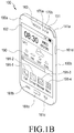
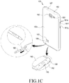
- FIG. 1b is a front perspective view of the mobile apparatus and FIG. 1c is a rear perspective view of the mobile apparatus.
- the display unit 190 is disposed on a center of a front surface 100a of the apparatus 100.
- the display unit 190 has a large size to occupy most of the front surface 100a of the apparatus 100.
- FIG. 1b shows an example where a main home screen is displayed on the display unit 190.
- the main home screen is a screen displayed when power is turned on or after a screen lock is released and is first displayed on the display unit 190.
- the main home screen may be a first home screen or a preset home screen of the home screens of several pages.
- Short-cut icons 191-1, 191-2, and 191-3 for executing frequently used applications, a main menu switching key 191-4, time, weather and the like may be displayed on the home screen.
- the main menu switching key 191-4 displays a menu screen on the display unit 190.
- a status bar 192 which shows a status of the apparatus 100 such as a battery charging status, intensity of a received signal, and a current time may be formed on an upper end of the display unit 190.
- the controller 110 may provide the UI, the virtual buttons, or the key input window provided by the key input method to the display unit 190, and the display unit 190 may display the UI, the virtual buttons, or the key input window provided by the key input method.
- a home button 161a, a menu button 161b, and a back button 161c may be formed below the display unit 190.
- the home button 161a, the menu button 161b, and the back button 161c are located below the display unit 190 as separated hardware keys as illustrated in FIG. 1b , but the keys of the present invention are not limited thereto.
- the home button 161a, the menu button 161b, and the back button 161c may be located at an area of the display unit 190, for example, below the shortcut icons 191-1, 191-2, and 191-3 as virtual buttons such as icons or UIs to perform functions of the home button 161a, the menu button 161b, and the back button 161c.
- the home button 161a displays the main home screen on the display unit 190.
- the main home screen may be displayed on the display unit 190.
- the home button 161a is pressed while applications are executed on the display unit 190, the main home screen illustrated in FIG. 1b may be displayed on the display unit 190.
- the home button 161a may be used to display recently used applications or a task manager on the display unit 190.
- the menu button 161b provides a connection menu which can be used on the display unit 190.
- the connection menu includes a widget addition menu, a background changing menu, a search menu, an editing menu and an environment setup menu, for example.
- the back button 161c may display the screen which was executed just before the currently executed screen or end the most recently used application.
- the first camera 151, an illumination sensor 170a, and a proximity sensor 170b may be disposed on edges of the front surface 100a of the apparatus 100.
- the second camera 152, the flash 153, and the speaker 163 may be disposed on a rear surface 100c of the apparatus 100.
- a power/reset button 161d, a volume button 161b, a terrestrial DMB antenna 141a for reception of broadcasting, and one or more microphones 162 may be disposed on a side surface 100b of the apparatus 100.
- the DMB antenna 141a may be fixed to the apparatus 100 or may be formed to be detachable from the apparatus 100.
- the connector 165 is formed on a lower side surface of the apparatus 100.
- a plurality of electrodes are formed in the connector 165, and the connector 165 may be connected to an external device through a wire.
- the earphone connecting jack 167 may be formed on an upper side surface of the apparatus 100. An earphone may be inserted into the earphone connecting jack 167.
- the stylus pen 168 and a hole that stores the stylus pen 168 may be located at a lower side surface of the apparatus 100.
- the stylus pen 168 may be inserted into the apparatus 100 to be stored in the apparatus 100, and withdrawn and detached from the apparatus 100 when being used.
- Programs are performed through different computer means and recorded in a computer-readable medium.
- the computer-readable medium may include a program command, a data file, and a data structure individually or a combination thereof stored in the storage unit 175 of the apparatus 100, and the program command may be temporarily stored in the RAM 113 included in the controller 110.
- the controller 110 may control hardware components included in the apparatus 100 in accordance with program commands, temporarily or continuously store data generated and provide a UI required for executing the methods.
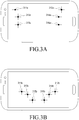
- FIG. 2 shows a flowchart of a method of operation of a key input method where in step S201 first touch inputs are identified in a preset number of areas for key input.
- step S202 input buttons are generated in the areas where the first touch inputs have been generated, respectively, and in step S203 a key input is processed corresponding to second touch inputs generated using the input buttons.
- a touch input medium for example, a user's finger
- the terminal initiates an operation of the key input method and determines whether the number of areas where the first touch inputs have been generated correspond to the preset number for the key input.
- the terminal identifies coordinates of areas where the first touch inputs have been generated.
- the terminal identifies that the first touch inputs are generated in areas 311a ⁇ b, 312a ⁇ b, 313a ⁇ b, 314a ⁇ b, 315a ⁇ b, and 316a ⁇ b illustrated in FIGs. 3a and 3b , or areas 311c ⁇ d, 312c ⁇ d, 313c ⁇ d, 314c ⁇ d, 315c ⁇ d, 316c ⁇ d, 317c ⁇ d, and 318c ⁇ d illustrated in FIGs. 3c and 3d and identifies that the number of areas where the first touch inputs have been generated corresponds to the preset number (for example, six or eight) for the Braille input, so as to detect coordinate values of the areas where the first touch inputs have been generated.
- the preset number for example, six or eight
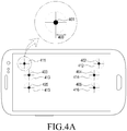
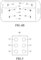
- the terminal sets input buttons corresponding to the areas where the first touch inputs have been generated such that the user in a specific class can more accurately perform the Braille input. For example, the terminal generates an input button 411 in an area within a preset radius 400 based on a point 401 where the first touch input has been generated as illustrated in FIG. 4a . Further, with respect to a plurality of points 401, 402, 403, 404, 405, and 406 where the first touch inputs have been generated, the terminal generates a plurality of input buttons 411, 412, 413, 414, 415, and 416 in the same way.
- the input button 411 is variably generated on the touch screen display in accordance with the first touch input by the user, and may be implemented by a virtual button such as a UI element or an icon formed by a predetermined program command.
- the terminal sets the input buttons 411, 412, 413, 414, 415, and 416 to have areas within the predetermined radius 400 based on the points 401, 402, 403, 404, 405, and 406 where the first touch inputs have been generated.
- users in a specific class such as blind people can more accurately perform Braille input without separately detecting or recognizing Braille areas preset during a terminal manufacturing step.
- the area of the input button within the predetermined radius 400 based on the point 401 where the first touch input has been generated may have a quadrangular shape or an oval shape having predetermined directivity in consideration of a characteristic of the touch input by the user as well as a circular shape. As illustrated in FIG.
- the terminal may divide the touch screen display into the number of areas where the first touch inputs have been generated based on the points 401, 402, 403, 404, 405, and 406 where the first touch inputs have been generated, and set the areas including the points 401, 402, 403, 404, 405, and 406 as the input buttons 421, 422, 423, 424, 425, and 426, respectively. Further, shapes or positions of the areas of the set input buttons may be changed according to a third touch input or several consecutive touch inputs by the user.
- a position of the touch input for a specific input button may be moved, and the terminal may track a position movement of the touch input by using a heuristic algorithm and differently change the shape or position of the area of a set input button.
- the terminal may set and display the area corresponding to the input button to be distinguishable from a background screen of the terminal such that the user can easily identify the input button.
- the terminal may provide proper vibration feedback or voice feedback to the area corresponding to the input button so that the user can identify the input.
- the terminal generates the input button in an area based on the first touch input generated in the area, thereby a key input can be conveniently and accurately performed without identification of a preset key area by the user.
- Braille is more likely to be used by users in a specific class (for example, blind people) having relatively poor sight, and thus the user in the specific class may see not all information displayed on the touch screen display.
- the user in the specific class having relatively poor sight has a difficulty in activating a mode (particularly, Braille input mode) for key input.
- Switching to a Braille input mode is advantageously achieved through generating the first touch input on the touch screen display using a touch input medium (for example, a user's finger).
- the terminal identifies whether the number of areas where the first touch inputs have been generated corresponds to the preset number for Braille input.
- the terminal may automatically switch to a mode for Braille input (Braille input mode). Accordingly, the user in the specific class having relatively poor sight may perform the key input more conveniently without complex interaction.
- the terminal configures a fixed preset Braille input virtual keyboard having a Braille input button on the touch screen display.
- a user in the specific class may have difficulty in distinguishing a preset Braille area and the system enables Braille input more conveniently and accurately without separately detecting or recognizing a preset Braille area.
- the terminal may also preset and store key input based on a preset input method. Further, when a second touch input is generated via an input button, the terminal may process the corresponding key input based on the preset key input in step S203. In steps S201 and S202, since the first touch input is made using both hands of the user, six, eight, or ten touch inputs may be simultaneously made.
- the input button is generated in the areas where the first touch inputs have been generated, there may be six, eight, or ten input buttons, for example.
- the system provides six, eight, or ten input buttons that can be differently combined, for example.
- Braille made for the special purpose of recognizing characters by blind people may advantageously use 6 Braille or 8 Braille.
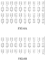
- the terminal may determine the preset input method as a 6 Braille input method. That is, in step S202, the terminal matches the preset input buttons (for example, input buttons 411, 412, 413, 414, 415, and 416) with first to sixth Braille areas 511, 512, 513, 514, 515, and 516 (see FIG. 5 ) included in 6 Braille input areas. For example, the terminal may perform the setting as illustrated in FIGs. 6a to 6c . Since positions of the input buttons are changed whenever the input buttons are set, the terminal may match the input buttons with the Braille areas in response to relative positions or arrangement types of the set input buttons.
- the preset input buttons for example, input buttons 411, 412, 413, 414, 415, and 416
- first to sixth Braille areas 511, 512, 513, 514, 515, and 516 included in 6 Braille input areas.
- the terminal may perform the setting as illustrated in FIGs. 6a to 6c . Since positions of the input buttons are changed
- the terminal may transmit feedback of whether the set input buttons are matched with the Braille areas or a matching state to the user. For example, the terminal may provide voice guidance of "6 Braille input method has been set", and make a request for identifying whether the input buttons are correctly matched with the Braille areas through voice guidance of "input "a"". When the user inputs "a” according to the voice guidance but the key input according to existing mapping does not correspond to "a", the mapping with the input buttons may be set again by rotating the Braille areas.
- the mapping may be made again by rotating the Braille areas by 180 degrees without changing positions of the input buttons. Further, the mapping between the input buttons and the Braille areas may be automatically modified by the terminal or may be modified by a control by the user. As a second touch input event is generated on the touch screen display by the user, a key input among the first, second, third, fourth, fifth, or sixth Braille area 511, 512, 513, 514, 515, and 516 of the 6 key input areas is identified.
- an area corresponding to a key input of the 6 Braille input method ( FIGs. 6a to 6c ) is identifies. For example, when the second touch input is generated in the input button 411 corresponding to the first Braille 511, the terminal identifies the input of a letter "a”. When the second touch input is generated in the input button 411 corresponding to the first Braille 511 and the input button 413 corresponding to the third Braille 513, the terminal identifies the input of a letter "b".
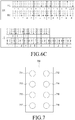
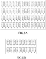
- the terminal may set the preset input method as an 8 Braille input method. That is, the terminal matches the input buttons set in step S202 with first to eighth Braille areas 711, 712, 713, 714, 715, 716, 717, and 718 (see FIG. 7 ) included in 8 Braille input areas.
- a second touch input is identified in an area comprising the first, second, third, fourth, fifth, sixth, seventh, or eighth Braille area 711, 712, 713, 714, 715, 716, 717, or 718 of the 8 Braille input areas.
- a point where the second touch input event has been generated enables identification of the corresponding key input (see FIGs. 8a and 8b ).
- the terminal identifies the input of a letter "a”.
- the terminal identifies the input of a letter "A”.
- the Braille input method may be performed in a plurality of modes, and key inputs may be differently recognized and processed according to each of the modes.
- the 6 Braille input method may include an English input mode, a number/special character input mode, and a Korean input mode.
- the second touch input When the second touch input is generated in the input button 411 corresponding to the first Braille 511, it may be identified and processed that a letter "a" is input in the English input mode and a number "1" is input in the number/special character input mode.
- the system detects a touch pattern comprising a touch input of one or more predetermined number of input buttons and associates an alphanumeric character with the detected touch pattern using a predetermined map associating different detected patterns with corresponding respective characters.
- the Braille input method including the plurality of modes may be set to be in a default mode (for example, English mode) when being operated, and may switch between the plurality of modes by a gesture input described below.
- the key input method may include a step for an operation of processing the input gesture.
- the operation of processing the input gesture may be performed after the switching to the key input mode in step S201 and before the end of the key input method, and may be initiated by a preset gesture input to perform the input gesture.
- FIG. 9 is a flowchart of a method of sequential operation for processing an input gesture of the key input method.
- the terminal first identifies the generation of an input gesture event having a predetermined pattern in step S901 and initiates the operation for processing the input gesture.
- the input gesture has a predetermined pattern and may be a motion gesture identified using a motion sensor of the terminal or a touch gesture input through the touch screen display included in the terminal.
- the terminal determines that a motion gesture event has been generated. Further, when it is detected that movement displacement of a drag gesture input through the touch screen display is equal to or larger than a preset touch gesture threshold, the terminal determines that a touch gesture event has been generated.
- the terminal determines whether the input gesture corresponds to the predetermined pattern.
- the predetermined pattern may include motion gestures and touch gestures shown in a Table of FIG. 10 .
- the motion gesture may include tilting, movement and rotation, for example of the terminal.
- the tilting may include gestures in which the terminal moves in a first direction 1101 such that an upper edge of the terminal is pushed, a second direction 1102 such that the upper edge of the terminal is pulled, a third direction 1103 such that a left edge of the terminal is pulled, and a fourth direction 1104 such that a right edge of the terminal is pulled.
- a first direction 1101 such that an upper edge of the terminal is pushed
- a second direction 1102 such that the upper edge of the terminal is pulled
- a third direction 1103 such that a left edge of the terminal is pulled
- a fourth direction 1104 such that a right edge of the terminal is pulled.
- the movement may include gestures in which the terminal moves in a direction 1111 (for example, an up direction) opposite to the ground, in a direction 1112 (for example, a down direction) toward the ground, in a left direction 1113, and a right direction 1114.
- the rotation may include gestures in which the terminal moves clockwise 1121 and counterclockwise 1122.
- the touch gesture may include a single touch drag and a multi touch drag.
- the single touch drag may include a drag gesture input by a single touch input as illustrated in FIGs. 12a to 12d
- the multi touch drag may include a drag gesture input in which a plurality of touch inputs move in the same direction (see FIGs.
- the terminal identifies a key input corresponding to the input gesture and performs an operation for processing the corresponding key input in step S903. For example, when a tilting motion gesture is generated by an action of tilting the terminal in the first direction 1101, the terminal may process an enter key input. When a tilting motion gesture is generated by an action of tilting the terminal in the second direction 1102, the terminal may process an input of changing the input mode (for example, English input mode, number/special character mode, and Korean input mode).
- the input mode for example, English input mode, number/special character mode, and Korean input mode.
- the terminal may process a space key input.
- the terminal may process a backspace key input.
- the terminal moves a position of a cursor within a character input window in proportion to a movement direction and a size of movement displacement of the terminal.
- the terminal moves the cursor in a direction corresponding to the direction of the single touch drag within a character input window, and a movement degree of the cursor is reflected in proportion to a size of movement displacement For example, as illustrated in FIG.
- the terminal may move the cursor existing in a character input window 1205a in a left direction 1202a corresponding to the drag direction, and determine a movement degree 1204a of the cursor in proportion to a length 1203a by which the drag of the single touch 1200a has been input.
- the terminal may move the cursor existing in a character input window 1205b in a right direction 1202b, and determine a movement degree 1204b of the cursor in proportion to a length 1203b by which the drag of the single touch 1200b has been input.
- a single touch drag may be input in different directions and the cursor may be moved in accordance with the single touch drag input in the different directions. For example, as illustrated in FIGs. 12c and 12d , even though single touch drags 1200c and 1200d are input in diagonal directions, the terminal may move cursors 1202c and 1202d within character input windows 1205c and 1205d in accordance with progress directions 1201c and 1201d and progress lengths 1203c and 1203d of the single touch drags in the same way as described above.
- the terminal may delete characters existing in the corresponding areas while moving the cursor in a direction corresponding to the direction of the multi touch drag. For example, as illustrated in FIG. 12e , as a multi touch 1200e is dragged in a left direction 1201e, the terminal may delete an input character existing in the corresponding area while moving the cursor existing in a character input window 1200e in a left direction 1202e corresponding to the drag direction. The terminal may determine a movement degree 1204e of the cursor within the input window in proportion to a length 1203e by which the drag of the multi touch 1200e has been input. Similarly, as illustrated in FIG.
- the terminal may reflect a movement degree 1204f of the cursor in proportion to a length 1203f by which the multi touch 1200f has been input and delete an input character existing in the corresponding area while moving the cursor existing in a character input window 1200f in a right direction 1202f.
- a cursor may be moved in accordance with the multi touch drag input in different directions. For example, as illustrated in FIGs.
- the terminal may delete input characters within character input windows 1205g and 1205h in accordance with progress directions 1201g and 1201h and progress lengths 1203g and 1203h of the multi touch drags in the same way as described above. Further, the terminal may end the key input method with the input of the multi touch drag moving in different directions. For example, as illustrated in FIG. 13a , as a first multi touch input 1301a is dragged in a first direction 1303a and a second multi touch input 1302a is dragged in a second direction 1304a opposite to the first direction 1303a, the terminal may end the key input method. Similarly, as illustrated in FIG.
- the terminal may end the key input method.
- Different modifications can be applied.
- the terminal may end the key input method as the first multi touch input 1301a and the second multi touch input 1302a are input in facing directions toward a center of the touch screen display as illustrated in FIG. 13a , or as the first multi touch input 1301b and the second multi touch input 1302b are input in crossing directions toward a center of the touch screen display as illustrated in FIG. 13b , the terminal may end the key input method.
- the exemplary embodiments of the system may be implemented in a form of hardware, software, or a combination of hardware and software.
- Such software may be stored, for example, in a volatile or non-volatile storage device such as a ROM, a memory such as a RAM, a memory chip, a memory device, or a memory IC, or a recordable optical or magnetic medium such as a CD, a DVD, a magnetic disk, or a magnetic tape, regardless of its ability to be erased or its ability to be re-recorded.
- the memory included in the mobile terminal is one example of machine-readable devices suitable for storing a program including instructions that are executed by a processor device to thereby implement embodiments of the present invention.
- the present invention includes a program for a code implementing the apparatus and method described in the appended claims of the specification and a machine (a computer or the like)-readable storage medium for storing the program.
- a program as described above can be electronically transferred through an arbitrary medium such as a communication signal transferred through cable or wireless connection.
- the above-described mobile terminal can receive the program from a program provision device which is connected thereto in a wired or wireless manner, and store the program.
- a program providing apparatus may include a program including instructions to perform a preset contents protection method, a memory for storing information required for the contents protection method, a communication unit for performing wired or wireless communication, and a controller for controlling program transmission.
- the program providing apparatus may provide the program to the portable terminal through a wire or wirelessly. Further, even when there is no request for providing the program from the portable terminal, for example, when the portable terminal is located within a particular place, the program providing apparatus may provide the program to the portable terminal through a wire or wirelessly.
- the above-described embodiments can be implemented in hardware, firmware or via the execution of software or computer code that can be stored in a recording medium such as a CD ROM, a Digital Versatile Disc (DVD), a magnetic tape, a RAM, a floppy disk, a hard disk, or a magneto-optical disk or computer code downloaded over a network originally stored on a remote recording medium or a non-transitory machine readable medium and to be stored on a local recording medium, so that the methods described herein can be rendered via such software that is stored on the recording medium using a general purpose computer, or a special processor or in programmable or dedicated hardware, such as an ASIC or FPGA.
- a recording medium such as a CD ROM, a Digital Versatile Disc (DVD), a magnetic tape, a RAM, a floppy disk, a hard disk, or a magneto-optical disk or computer code downloaded over a network originally stored on a remote recording medium or a non-transitory machine readable
- the computer, the processor, microprocessor controller or the programmable hardware include memory components, e.g., RAM, ROM, Flash, etc. that may store or receive software or computer code that when accessed and executed by the computer, processor or hardware implement the processing methods described herein.
- memory components e.g., RAM, ROM, Flash, etc.
- the execution of the code transforms the general purpose computer into a special purpose computer for executing the processing shown herein.
- the functions and process steps herein may be performed automatically or wholly or partially in response to user command. An activity (including a step) performed automatically is performed in response to executable instruction or device operation without user direct initiation of the activity.
Description
- The present system concerns a touch screen based user interface and data input unit.
- Known mobile devices store and execute installed applications manufactured by a manufacturer of the device apparatus as well as additional applications downloaded from the Internet, for example. The additional applications may registered on the website that sells applications and tens of thousands to hundreds of thousands of applications are currently available to be provided to a mobile device free of charge or at a cost dependent on type of destination mobile device. Accordingly, typically hundreds of applications are stored in a mobile device such as a smart phone or a tablet Personal Computer (PC), and shortcut keys for executing the applications are displayed on a display of a touch screen of the mobile device as icons. A user may touch one of the icons displayed on the display of the touch screen to execute a desired application in the mobile device.
- A virtual keyboard on the display of the touch screen is a user interface and gateway to the applications and it is desirable to have a user friendly interface supporting quick user navigation to desired applications and functions.
-
WO 2012/048380 discloses a method of providing an interface comprising receiving contact information indicative of points of contact between fingers of at least one hand and a surface. The method further comprising mapping onto the surface a plurality of interface elements each corresponding to a key on a keyboard, each element being assigned to one of a plurality of groups, each group having an associated one of the fingers for activation of the elements in the group, wherein each group is mapped to the surface in accordance with contact information for the associated finger. Another aspect of the inventive include recurrently receiving the contact information and recurrently mapping each group to the surface in accordance with the contact information for the associated finger so that the group tracks the resting position of the associated finger. - Mario Romero et al., "BrailleTouch: Designing a Mobile Eyes-Free Soft Keyboard," MOBILEHCI 2011, 30 August 2011, pages 707-709, discloses a soft keyboard, for eyes-free mobile text entry, which can be incorporated into existing mobile touch screen devices.
- "Braille dynamic virtual keyboard for iPhone, iPod touch, iPad," 5 March 2011, (URL: https://www. Youtube.com/watch?v=k5snVu5q2b8) discloses a video for a mobile application comprising a Braille dynamic virtual keyboard.
- Shiri Azenkot et al., "Input finger detection for nonvisual touch screen text entry in Perkinput", 28 may 2012, pages 121-129 (ISBN: 978-1-4503-1420-6), discloses input finger detection, a technique for nonvisual touch screen input and a related application, the Perkinput text entry method.
-
EP-2450783-A1 discloses an adaptive virtual keyboard for a handheld device. - A system supports accurate key input of characters in response to user touch, reduces keying errors, and recognizes a position of an input button by forming a virtual keyboard for a Braille input on an area where a touch input is made by the user, even in a condition where the user does not see the virtual keyboard.
- The technical solution is provided by the present invention which is defined by the appended claims.
- Certain embodiments aim to achieve the technical effect of enhancing the precision of an input device.
- Certain embodiments aim to achieve the technical effect of lowering a burden (e.g. a cognitive, operative, operational, operating, or manipulative burden) of a user when performing certain computer or device interactions.
- Certain embodiments aim to achieve the technical effect of providing a more efficient man-machine (user-machine) interface.
- The above and other aspects, features, and advantages of the system will be more apparent from the following detailed description taken in conjunction with the accompanying drawings, in which:
-
FIG. 1a shows a portable terminal according to invention principles; -
FIG. 1b shows a front perspective view of a portable terminal according to invention principles; -
FIG. 1c shows a rear perspective view of a portable terminal according to invention principles; -
FIG. 2 shows a flowchart of a method of key input operation according to invention principles; -
FIGs. 3a to 3d show identification of a first touch input according to invention principles; -
FIGs. 4a and4b show input buttons provided by a key input method according to invention principles; -
FIG. 5 shows 6 Braille matching input buttons used in a key input method according to invention principles; -
FIGs. 6a to 6c show characters allocated to input buttons by a key input method according to invention principles; -
FIG. 7 shows 8 Braille matching input buttons used by a key input method according to invention principles; -
FIGs. 8a and 8b show characters allocated to input buttons by a key input method according to invention principles; -
FIG. 9 shows a flowchart of a method of operation for processing an input gesture included in a key input method according to invention principles; -
FIG. 10 shows an input gesture set by a key input method according to invention principles; -
FIGs. 11a to 11c show a motion gesture which can be generated in a key input method according to invention principles; -
FIGs. 12a to 12h show a touch gesture which can be generated in a key input method according to invention principles; and -
FIGs. 13a and 13b show a touch gesture which can be generated in a key input method according to invention principles. - Hereinafter, specific examples of a system will be described with reference to the accompanying drawings. The same reference numerals represented in each of the drawings indicate the elements that perform substantially the same functions.
- While terms including ordinal numbers, such as "first" and "second," etc., may be used to describe various components, such components are not limited by the above terms. The terms are used merely for the purpose to distinguish an element from the other elements. For example, a first element could be termed a second element, and similarly, a second element could be also termed a first element without departing from the scope. As used herein, the singular forms are intended to include the plural forms as well, unless the context clearly indicates otherwise.
-
FIG. 1a shows amobile apparatus 100 that may be connected with an external device (not shown) by using an external device connector such as asub communication module 130, aconnector 165, and anearphone connecting jack 167. The "external device" may include various devices attached to or detached from theapparatus 100 through a wire, such as an earphone, an external speaker, a Universal Serial Bus (USB) memory, a charger, a cradle/dock, a Digital Multimedia Broadcasting (DMB) antenna, a mobile payment related device, a health management device (blood sugar tester or the like), a game machine, a car navigation device and the like. Further, the "external device" may include a Bluetooth™ communication device, a short distance communication device such as a Near Field Communication (NFC) device, a WiFi Direct communication device, and a wireless Access Point (AC) which may be wirelessly connected to theapparatus 100. In addition, the external device may include another device, a mobile phone, a smart phone, a tablet PC, a desktop PC, and a server. -
Apparatus 100 includes adisplay unit 190 and adisplay controller 195. Further, theapparatus 100 includes acontroller 110, amobile communication module 120, asub communication module 130, amultimedia module 140, acamera module 150, aGPS module 155, an input/output module 160, asensor module 170, astorage unit 175, and apower supplier 180. Thesub communication module 130 includes at least one of awireless LAN module 131 and a shortdistance communication module 132, and themultimedia module 140 includes at least one of abroadcasting communication module 141, anaudio reproduction module 142, and avideo reproduction module 143. Thecamera module 150 includes at least one of afirst camera 151 and asecond camera 152. The input/output module 160 includes at least one of abutton 161, amicrophone 162, aspeaker 163, avibration motor 164, aconnector 165, and akeypad 166. - The
controller 110 may include aCPU 111, a Read Only Memory (ROM) 112 storing a control program for controlling theapparatus 100, and a Random Access Memory (RAM) 113 used as a storage area for storing a signal or data input from the outside of theapparatus 100 or for an operation performed in theapparatus 100. TheCPU 111 includes a single core, a dual core, a triple core, or a quadruple core. TheCPU 111, theROM 112, and theRAM 113 may be mutually connected to each other through an internal bus. Thecontroller 110 may control themobile communication module 120, thesub communication module 130, themultimedia module 140, thecamera module 150, theGPS module 155, the input/output module 160, thesensor module 170, thestorage unit 175, thepower supplier 180, thedisplay unit 190, and thedisplay controller 195. - The
mobile communication module 120 enables theapparatus 100 to be connected with an external device through mobile communication by using one antenna or a plurality of antennas (not shown) according to a control of thecontroller 110. Themobile communication module 120 transmits/receives a wireless signal for a voice call, a video call, a Short Message Service (SMS), or a Multimedia Message Service (MMS) to/from a mobile phone (not shown), a smart phone (not shown), a tablet PC, or another device (not shown) using a phone number input into theapparatus 100. Thesub communication module 130 may include at least one of thewireless LAN module 131 and the shortdistance communication module 132. For example, thesub communication module 130 may include thewireless LAN module 131, the nearfield communication module 132, or both thewireless LAN module 131 and the nearfield communication module 132. - The
wireless LAN module 131 may be Internet-connected in a place where a wireless Access Point (AP) (not shown) is installed according to a control of thecontroller 110. Thewireless LAN module 131 supports a wireless LAN standard (IEEE802.11x) of the Institute of Electrical and Electronics Engineers (IEEE). The shortdistance communication module 132 may wirelessly perform short distance communication between theapparatus 100 and an image forming apparatus (not shown) according to a control of thecontroller 110. A short distance communication scheme may include Bluetooth™, Infrared Data Association (IrDA) communication, WiFi-Direct communication, Near Field Communication (NFC) and the like. Theapparatus 100 may include at least one of themobile communication module 120, thewireless LAN module 131, and the shortdistance communication module 132. For example, theapparatus 100 may include a combination of themobile communication module 120, thewireless LAN module 131, and the shortdistance communication module 132 according to a capability thereof. - The
multimedia module 140 may include thebroadcasting communication module 141, theaudio reproduction module 142, or thevideo reproduction module 143. Thebroadcasting communication module 141 may receive a broadcasting signal (for example, a TV broadcasting signal, a radio broadcasting signal, or a data broadcasting signal) and broadcasting supplement information (for example, Electric Program Guide: EPG or Electric Service Guide: ESG) output from a broadcasting station through a broadcasting communication antenna (not shown) according to a control of thecontroller 110. Theaudio reproduction module 142 may reproduce a digital audio file (for example, a file having a file extension of mp3, wma, ogg, or wav) stored or received according to a control of thecontroller 110. Thevideo reproduction module 143 may reproduce a digital video file (for example, a file having a file extension of mpeg, mpg, mp4, avi, mov, or mkv) stored or received according to a control of thecontroller 110. Thevideo reproduction module 143 may reproduce the digital audio file. - The
multimedia module 140 may include theaudio reproduction module 142 or thevideo reproduction module 143 and exclude thebroadcasting communication module 141. Further, theaudio reproduction module 142 or thevideo reproduction module 143 of themultimedia module 140 may be included in thecontroller 110. Thecamera module 150 may include at least one of thefirst camera 151 and thesecond camera 152 for acquiring a still image or a video in response to control of thecontroller 110. Further, thefirst camera 151 or thesecond camera 152 may include an auxiliary light source (for example, a flash (not shown) providing light required for the photographing. Thefirst camera 151 may be disposed on a front surface of theapparatus 100, and thesecond camera 152 may be disposed on a back surface of theapparatus 100. Alternatively, thefirst camera 151 and thesecond camera 152 are closely located to each other (for example, an interval between thefirst camera 151 and thesecond camera 152 is larger than 1 cm and smaller than 8 cm) and acquire a three dimensional still image or a three dimensional video. - The
GPS module 155 may receive radio waves from a plurality of GPS satellites (not shown) in Earth's orbit and calculate a position of theapparatus 100 by using Time of Arrival from the GPS satellites to theapparatus 100. The input/output module 160 may include at least one of a plurality ofbuttons 161, themicrophone 162, thespeaker 163, thevibration motor 164, theconnector 165, and thekeypad 166. Thebuttons 161 may be formed on a front surface, a side surface, or a back surface of a housing of theapparatus 100, and may include a power/lock button (not shown) and a volume button (not shown). Further, thebuttons 161 may include at least one of a menu button, a home button, a back button, and asearch button 161. Although it is described as an example that thebuttons 161 are separately arranged at the outside of the housing of theapparatus 100 in hardware, the buttons are not limited thereto. Thebuttons 161 may be displayed on an area of thedisplay unit 190 in a form of icons or UI elements, or implemented by virtual buttons configured to perform functions pre-allocated by a selection of the corresponding area. - The
microphone 162 receives a voice or a sound to generate an electrical signal in response to control of thecontroller 110. Thespeaker 163 may output sounds corresponding to various signals (for example, a wireless signal, a broadcasting signal, a digital audio file, a digital video file, taking a picture or the like) of themobile communication module 120, thesub communication module 130, themultimedia module 140, or thecamera module 150 to the outside of theapparatus 100 in response to control of thecontroller 110. Thespeaker 163 may output a sound (for example, button tone corresponding to a phone call or ringing tone) corresponding to a function performed by theapparatus 100. One ormore speakers 163 may be located in the housing of theapparatus 100. - The
vibration motor 164 may convert an electrical signal to a mechanical vibration according to a control of thecontroller 110. For example, when theapparatus 100 in a vibration mode receives a voice call from another device (not shown), thevibration motor 164 is operated. One ormore vibration motors 164 may be formed within the housing of theapparatus 100. Thevibration motor 164 may operate in response to a touch action of the user made on the touch screen or successive motions of the touch on thedisplay unit 190. Theconnector 165 may be used as an interface for connecting theapparatus 100 with an external device (not shown) or a power source (not shown). Theapparatus 100 may transmit or receive data stored in thestorage unit 175 of theapparatus 100 to or from an external device (not shown) through a wired cable connected to theconnector 165 according to a control of thecontroller 110. Further, theapparatus 100 may receive power from a power source (not shown) through the wired cable connected to theconnector 165 or charge a battery (not shown) by using the power source. - The
keypad 166 may receive a key input from the user to control theapparatus 100. Thekeypad 166 includes a physical keypad (not shown) formed in theapparatus 100 or a virtual keypad (not shown) displayed on thedisplay unit 190. The physical keypad (not shown) formed in theapparatus 100 may be omitted. An earphone (not shown) may be inserted into theearphone connecting jack 167 to be connected withapparatus 100. Astylus pen 168 may be inserted into theapparatus 100 to be stored in theapparatus 100, and withdrawn and detached from the apparatus100 when being used. A pen attachment/detachment recognition switch 169 operating in accordance with attachment or detachment of thestylus pen 168 is located at one area within theapparatus 100 into which thestylus pen 168 is inserted, and thus signals corresponding to the attachment and the detachment of thestylus pen 168 may be provided to thecontroller 110. The pen attachment/detachment recognition switch 169 is located at one area into which thestylus pen 168 is inserted to directly or indirectly contact thestylus pen 168 when thestylus pen 168 is mounted. Accordingly, the pen attachment/detachment recognition switch 169 generates a signal corresponding to the attachment or the detachment of thestylus pen 168 based on the direct or indirect contact with thestylus pen 168 and provides the generated signal to thecontroller 110. - The
sensor module 170 includes at least one sensor for detecting a state of theapparatus 100. For example, thesensor module 170 may include a proximity sensor for detecting whether the user approaches theapparatus 100, an illuminance sensor (not shown) for detecting an amount of ambient light of theapparatus 100, a motion sensor (not shown) for detecting an operation (for example, a rotation of theapparatus 100, or an acceleration or a vibration applied to the apparatus 100) of theapparatus 100, a geo-magnetic sensor (not shown) for detecting a point of the compass by using the Earth's magnetic field, a gravity sensor for detecting an action direction of the gravity, and an altimeter for measuring an atmospheric pressure to detect an altitude. At least one sensor may detect a state, generate a signal corresponding to the detection, and transmit the signal to thecontroller 110. - The
storage unit 175 may store an input/output signal or data corresponding to the operation of thecommunication module 120, thesub communication module 130, themultimedia module 140, thecamera module 150, theGPS module 155, the input/output module 160, thesensor module 170, or thedisplay unit 190. Thestorage unit 175 may store a control program and applications for controlling theapparatus 100 or thecontroller 110. The term "storage unit" includes thestorage unit 175, theROM 112 and theRAM 113 within thecontroller 110, or a memory card (not shown) (for example, an SD card or a memory stick) installed in theapparatus 100. The storage unit may include a non-volatile memory, a volatile memory, a Hard Disk Drive (HDD), or a Solid State Drive (SSD). - The
storage unit 175 may store program commands for processing steps included in a key input method, that is, a step of identifying a first touch input in areas preset for the key input, a step of generating input buttons including virtual buttons in the areas where the first touch input has been generated, and a step of processing a key input corresponding to a second touch input generated by the input button. Thecontroller 110 reads the program commands for executing the key input method and controls hardware components included in theapparatus 100 based on the program commands. Further, thecontroller 110 may temporarily or continuously store data generated while the program commands are executed in thestorage unit 175, display a UI required for performing the key input method on thedisplay unit 190, or receive an input through the displayed UI. Thepower supplier 180 may supply power to one or more batteries (not shown) arranged at the housing of theapparatus 100 according to a control of thecontroller 110. The one or more batteries (not shown) supply power to theapparatus 100. Further, thepower supplier 180 may supply power input from an external power source (not shown) through a wired cable connected to theconnector 165 to theapparatus 100. In addition, thepower supplier 180 may supply power wirelessly input from the external power source through a wireless charging technology to theapparatus 100. - The
display controller 195 receives different information (for example, information generated to perform a call, data transmission, broadcasting, photography) processed by thecontroller 110, converts the received different information to data which can be displayed by thedisplay unit 190, and provides the data to thedisplay unit 190. Thedisplay unit 190 displays the data received from thedisplay controller 195. For example, thedisplay unit 190 may display a User Interface (UI) or a Graphic User Interface (GUI) related to a call in a call mode. Thedisplay unit 190 may include at least one of a liquid crystal display, a thin film transistor-liquid crystal display, an organic light-emitting diode, a flexible display, a 3d display, and an electrophoretic display. - Further, the
display unit 190 may be used as an input device as well as an output device, and accordingly, may include a touch screen panel. In addition, thedisplay unit 190 may transmit an analog signal corresponding to at least one touch input through the UI or the GUI to thedisplay controller 195. Thedisplay unit 190 may detect one or more touches input through a user's body (for example, fingers including a thumb) or a touchable input means (for example, a stylus pen). Thedisplay unit 190 may receive successive motions of the touch among the one or more touches and transmit an analog signal corresponding to the successive motions to thedisplay controller 195. Thedisplay unit 190 may detect one or more touches in a resistive type, a capacitive type, an infrared type, or an acoustic wave type. - The touch according to the present invention is not limited to the contact between the
display unit 190 and the user's body or the touchable input means, and may include a non-contact (for example, a detectable interval between thedisplay unit 190 and the user's body or the touchable input means is smaller than or equal to 1 mm). The detectable interval on thedisplay unit 190 may be changed according to a capability or a structure of theapparatus 100. Particularly, thedisplay unit 190 may output different values (for example, including current values) detected by a touch event and a hovering event so that the touch event by a contact with the user's body or the touchable input unit and the input event (for example, the hovering event) in a noncontact state can be distinguishably detected. Further, it is preferable that thedisplay unit 190 differently outputs detected values (for example, current values) based on a distance between thedisplay unit 190 and a space where the hovering event is generated. - The
display controller 195 converts an analog signal received from thedisplay unit 190 to a digital signal (for example, X and Y coordinates) and transmits the converted digital signal to thecontroller 110. Thecontroller 110 may control thedisplay unit 190 by using the digital signal received from thedisplay controller 195. For example, thecontroller 110 may allow a short-cut icon (not shown) displayed on thedisplay unit 190 to be selected or executed in response to a touch event or a hovering event. Further, thedisplay controller 195 may be included in thecontroller 110. Thescreen controller 195 may identify a distance between a space where the hovering event is generated and thedisplay unit 190 by detecting a value (for example, a current value) output through thedisplay unit 190, convert the identified distance value to a digital signal (for example, a Z coordinate), and provide the converted digital signal to thecontroller 110. - Further, the
display unit 190 may include two or more touch screen panels which can detect touches or approaches of the user's body and the touchable input unit in order to sequentially or simultaneously receive inputs by the user's body and the touchable input unit. The two or more touch screen panels provide different output values to thedisplay controller 195, and thedisplay controller 195 may differently recognize the values input into the two or more touch screen panels to distinguish whether the input from the touch screen is an input by the user's body or an input by the touchable input unit. -
FIG. 1b is a front perspective view of the mobile apparatus andFIG. 1c is a rear perspective view of the mobile apparatus. Referring toFIGs. 1b and1c , thedisplay unit 190 is disposed on a center of afront surface 100a of theapparatus 100. Thedisplay unit 190 has a large size to occupy most of thefront surface 100a of theapparatus 100.FIG. 1b shows an example where a main home screen is displayed on thedisplay unit 190. The main home screen is a screen displayed when power is turned on or after a screen lock is released and is first displayed on thedisplay unit 190. Further, when theapparatus 100 has different home screens of several pages, the main home screen may be a first home screen or a preset home screen of the home screens of several pages. Short-cut icons 191-1, 191-2, and 191-3 for executing frequently used applications, a main menu switching key 191-4, time, weather and the like may be displayed on the home screen. The main menu switching key 191-4 displays a menu screen on thedisplay unit 190. Further, astatus bar 192 which shows a status of theapparatus 100 such as a battery charging status, intensity of a received signal, and a current time may be formed on an upper end of thedisplay unit 190. As functions (for example, inputting a caller's number in a call application, inputting text in a text message application, inputting text in an Instant Message (IM) application, and inputting a character (or number) in a search application) are executed, thecontroller 110 may provide the UI, the virtual buttons, or the key input window provided by the key input method to thedisplay unit 190, and thedisplay unit 190 may display the UI, the virtual buttons, or the key input window provided by the key input method. - A
home button 161a, amenu button 161b, and aback button 161c may be formed below thedisplay unit 190. Thehome button 161a, themenu button 161b, and theback button 161c are located below thedisplay unit 190 as separated hardware keys as illustrated inFIG. 1b , but the keys of the present invention are not limited thereto. For example, thehome button 161a, themenu button 161b, and theback button 161c may be located at an area of thedisplay unit 190, for example, below the shortcut icons 191-1, 191-2, and 191-3 as virtual buttons such as icons or UIs to perform functions of thehome button 161a, themenu button 161b, and theback button 161c. Thehome button 161a displays the main home screen on thedisplay unit 190. For example, when thehome button 161a is pressed in a state where a home screen different from the main home screen or the menu screen is displayed on thedisplay unit 190, the main home screen may be displayed on thedisplay unit 190. Further, when thehome button 161a is pressed while applications are executed on thedisplay unit 190, the main home screen illustrated inFIG. 1b may be displayed on thedisplay unit 190. In addition, thehome button 161a may be used to display recently used applications or a task manager on thedisplay unit 190. - The
menu button 161b provides a connection menu which can be used on thedisplay unit 190. The connection menu includes a widget addition menu, a background changing menu, a search menu, an editing menu and an environment setup menu, for example. Theback button 161c may display the screen which was executed just before the currently executed screen or end the most recently used application. Thefirst camera 151, anillumination sensor 170a, and aproximity sensor 170b may be disposed on edges of thefront surface 100a of theapparatus 100. Thesecond camera 152, theflash 153, and thespeaker 163 may be disposed on arear surface 100c of theapparatus 100. For example, a power/reset button 161d, avolume button 161b, aterrestrial DMB antenna 141a for reception of broadcasting, and one ormore microphones 162 may be disposed on aside surface 100b of theapparatus 100. TheDMB antenna 141a may be fixed to theapparatus 100 or may be formed to be detachable from theapparatus 100. Further, theconnector 165 is formed on a lower side surface of theapparatus 100. A plurality of electrodes are formed in theconnector 165, and theconnector 165 may be connected to an external device through a wire. Theearphone connecting jack 167 may be formed on an upper side surface of theapparatus 100. An earphone may be inserted into theearphone connecting jack 167. Thestylus pen 168 and a hole that stores thestylus pen 168 may be located at a lower side surface of theapparatus 100. Thestylus pen 168 may be inserted into theapparatus 100 to be stored in theapparatus 100, and withdrawn and detached from theapparatus 100 when being used. Programs are performed through different computer means and recorded in a computer-readable medium. The computer-readable medium may include a program command, a data file, and a data structure individually or a combination thereof stored in thestorage unit 175 of theapparatus 100, and the program command may be temporarily stored in theRAM 113 included in thecontroller 110. Accordingly, thecontroller 110 may control hardware components included in theapparatus 100 in accordance with program commands, temporarily or continuously store data generated and provide a UI required for executing the methods. -
FIG. 2 shows a flowchart of a method of operation of a key input method where in step S201 first touch inputs are identified in a preset number of areas for key input. In step S202 input buttons are generated in the areas where the first touch inputs have been generated, respectively, and in step S203 a key input is processed corresponding to second touch inputs generated using the input buttons. When the first touch input by a touch input medium (for example, a user's finger) is generated on a touch screen display in step S201, the terminal initiates an operation of the key input method and determines whether the number of areas where the first touch inputs have been generated correspond to the preset number for the key input. When the first touch inputs corresponding to the preset number for the key input are generated, the terminal identifies coordinates of areas where the first touch inputs have been generated. - For example, in step S201, the terminal identifies that the first touch inputs are generated in
areas 311a∼b, 312a∼b, 313a∼b, 314a∼b, 315a∼b, and 316a∼b illustrated inFIGs. 3a and 3b , orareas 311c∼d, 312c∼d, 313c∼d, 314c∼d, 315c∼d, 316c∼d, 317c∼d, and 318c∼d illustrated inFIGs. 3c and 3d and identifies that the number of areas where the first touch inputs have been generated corresponds to the preset number (for example, six or eight) for the Braille input, so as to detect coordinate values of the areas where the first touch inputs have been generated. - In step S202, the terminal sets input buttons corresponding to the areas where the first touch inputs have been generated such that the user in a specific class can more accurately perform the Braille input. For example, the terminal generates an
input button 411 in an area within apreset radius 400 based on apoint 401 where the first touch input has been generated as illustrated inFIG. 4a . Further, with respect to a plurality ofpoints input buttons input button 411 is variably generated on the touch screen display in accordance with the first touch input by the user, and may be implemented by a virtual button such as a UI element or an icon formed by a predetermined program command. - The terminal sets the
input buttons predetermined radius 400 based on thepoints predetermined radius 400 based on thepoint 401 where the first touch input has been generated may have a quadrangular shape or an oval shape having predetermined directivity in consideration of a characteristic of the touch input by the user as well as a circular shape. As illustrated inFIG. 4b , the terminal may divide the touch screen display into the number of areas where the first touch inputs have been generated based on thepoints points input buttons - In step S202, the terminal may set and display the area corresponding to the input button to be distinguishable from a background screen of the terminal such that the user can easily identify the input button. In addition, the terminal may provide proper vibration feedback or voice feedback to the area corresponding to the input button so that the user can identify the input. The terminal generates the input button in an area based on the first touch input generated in the area, thereby a key input can be conveniently and accurately performed without identification of a preset key area by the user. Braille is more likely to be used by users in a specific class (for example, blind people) having relatively poor sight, and thus the user in the specific class may see not all information displayed on the touch screen display. Accordingly, the user in the specific class having relatively poor sight has a difficulty in activating a mode (particularly, Braille input mode) for key input. Switching to a Braille input mode is advantageously achieved through generating the first touch input on the touch screen display using a touch input medium (for example, a user's finger). In response to first touch inputs on the touch screen display, the terminal identifies whether the number of areas where the first touch inputs have been generated corresponds to the preset number for Braille input. As the first touch inputs corresponding to the preset number of the Braille input are generated, the terminal may automatically switch to a mode for Braille input (Braille input mode). Accordingly, the user in the specific class having relatively poor sight may perform the key input more conveniently without complex interaction.
- Further, the terminal configures a fixed preset Braille input virtual keyboard having a Braille input button on the touch screen display. A user in the specific class may have difficulty in distinguishing a preset Braille area and the system enables Braille input more conveniently and accurately without separately detecting or recognizing a preset Braille area. The terminal may also preset and store key input based on a preset input method. Further, when a second touch input is generated via an input button, the terminal may process the corresponding key input based on the preset key input in step S203. In steps S201 and S202, since the first touch input is made using both hands of the user, six, eight, or ten touch inputs may be simultaneously made. Further, since the input button is generated in the areas where the first touch inputs have been generated, there may be six, eight, or ten input buttons, for example. The system provides six, eight, or ten input buttons that can be differently combined, for example. Further, Braille made for the special purpose of recognizing characters by blind people may advantageously use 6 Braille or 8 Braille.
- For example, when the number of input buttons set in steps S201 and S202 is six, the terminal may determine the preset input method as a 6 Braille input method. That is, in step S202, the terminal matches the preset input buttons (for example,
input buttons Braille areas FIG. 5 ) included in 6 Braille input areas. For example, the terminal may perform the setting as illustrated inFIGs. 6a to 6c . Since positions of the input buttons are changed whenever the input buttons are set, the terminal may match the input buttons with the Braille areas in response to relative positions or arrangement types of the set input buttons. Further, the terminal may transmit feedback of whether the set input buttons are matched with the Braille areas or a matching state to the user. For example, the terminal may provide voice guidance of "6 Braille input method has been set", and make a request for identifying whether the input buttons are correctly matched with the Braille areas through voice guidance of "input "a"". When the user inputs "a" according to the voice guidance but the key input according to existing mapping does not correspond to "a", the mapping with the input buttons may be set again by rotating the Braille areas. When the terminal randomly maps the input buttons and the Braille areas and then the input of "a" received from the user does not correspond to a firstBraille input 511 but corresponds to a sixthBraille input 516, the mapping may be made again by rotating the Braille areas by 180 degrees without changing positions of the input buttons. Further, the mapping between the input buttons and the Braille areas may be automatically modified by the terminal or may be modified by a control by the user. As a second touch input event is generated on the touch screen display by the user, a key input among the first, second, third, fourth, fifth, or sixthBraille area FIGs. 6a to 6c ) is identifies. For example, when the second touch input is generated in theinput button 411 corresponding to thefirst Braille 511, the terminal identifies the input of a letter "a". When the second touch input is generated in theinput button 411 corresponding to thefirst Braille 511 and theinput button 413 corresponding to thethird Braille 513, the terminal identifies the input of a letter "b". - In another example, when the number of input buttons set in step S202 is eight, the terminal may set the preset input method as an 8 Braille input method. That is, the terminal matches the input buttons set in step S202 with first to eighth
Braille areas FIG. 7 ) included in 8 Braille input areas. A second touch input is identified in an area comprising the first, second, third, fourth, fifth, sixth, seventh, or eighthBraille area FIGs. 8a and 8b ). For example, when the second touch input is generated in the input button corresponding to thefirst Braille 711, the terminal identifies the input of a letter "a". When the second touch input is generated in the input button corresponding to thefirst Braille 711 and the input button corresponding to theseventh Braille 717, the terminal identifies the input of a letter "A". The Braille input method may be performed in a plurality of modes, and key inputs may be differently recognized and processed according to each of the modes. For example, the 6 Braille input method may include an English input mode, a number/special character input mode, and a Korean input mode. When the second touch input is generated in theinput button 411 corresponding to thefirst Braille 511, it may be identified and processed that a letter "a" is input in the English input mode and a number "1" is input in the number/special character input mode. The system detects a touch pattern comprising a touch input of one or more predetermined number of input buttons and associates an alphanumeric character with the detected touch pattern using a predetermined map associating different detected patterns with corresponding respective characters. - As described above, the Braille input method including the plurality of modes may be set to be in a default mode (for example, English mode) when being operated, and may switch between the plurality of modes by a gesture input described below. The key input method may include a step for an operation of processing the input gesture. The operation of processing the input gesture may be performed after the switching to the key input mode in step S201 and before the end of the key input method, and may be initiated by a preset gesture input to perform the input gesture.
FIG. 9 is a flowchart of a method of sequential operation for processing an input gesture of the key input method. The terminal first identifies the generation of an input gesture event having a predetermined pattern in step S901 and initiates the operation for processing the input gesture. The input gesture has a predetermined pattern and may be a motion gesture identified using a motion sensor of the terminal or a touch gesture input through the touch screen display included in the terminal. In step S901, when it is detected that a sensor value input from the motion sensor is equal to or larger than a preset motion gesture threshold, the terminal determines that a motion gesture event has been generated. Further, when it is detected that movement displacement of a drag gesture input through the touch screen display is equal to or larger than a preset touch gesture threshold, the terminal determines that a touch gesture event has been generated. - In step S902, the terminal determines whether the input gesture corresponds to the predetermined pattern. For example, the predetermined pattern may include motion gestures and touch gestures shown in a Table of
FIG. 10 . The motion gesture may include tilting, movement and rotation, for example of the terminal. As illustrated inFIG. 11a , the tilting may include gestures in which the terminal moves in afirst direction 1101 such that an upper edge of the terminal is pushed, asecond direction 1102 such that the upper edge of the terminal is pulled, athird direction 1103 such that a left edge of the terminal is pulled, and afourth direction 1104 such that a right edge of the terminal is pulled. As illustrated inFIG. 11b , the movement may include gestures in which the terminal moves in a direction 1111 (for example, an up direction) opposite to the ground, in a direction 1112 (for example, a down direction) toward the ground, in aleft direction 1113, and aright direction 1114. Further, as illustrated inFIG. 11c , the rotation may include gestures in which the terminal moves clockwise 1121 and counterclockwise 1122. The touch gesture may include a single touch drag and a multi touch drag. The single touch drag may include a drag gesture input by a single touch input as illustrated inFIGs. 12a to 12d , and the multi touch drag may include a drag gesture input in which a plurality of touch inputs move in the same direction (seeFIGs. 12e to 12h ) and a drag gesture input in which a plurality of touch inputs move in different directions (see FIGs. 12I and 12J) as illustrated inFIGs. 12e to 12J . When the input gesture corresponds to the gesture shown in the Table ofFIG. 10 , the terminal identifies a key input corresponding to the input gesture and performs an operation for processing the corresponding key input in step S903. For example, when a tilting motion gesture is generated by an action of tilting the terminal in thefirst direction 1101, the terminal may process an enter key input. When a tilting motion gesture is generated by an action of tilting the terminal in thesecond direction 1102, the terminal may process an input of changing the input mode (for example, English input mode, number/special character mode, and Korean input mode). Further, when a tilting motion gesture is generated by an action of tilting the terminal in thethird direction 1103, the terminal may process a space key input. When a tilting motion gesture is generated by an action of tilting the terminal in thefourth direction 1104, the terminal may process a backspace key input. In addition, when a motion gesture is generated by a terminal movement, the terminal moves a position of a cursor within a character input window in proportion to a movement direction and a size of movement displacement of the terminal. Meanwhile, when the single touch drag is generated, the terminal moves the cursor in a direction corresponding to the direction of the single touch drag within a character input window, and a movement degree of the cursor is reflected in proportion to a size of movement displacement For example, as illustrated inFIG. 12a , as asingle touch 1200a is dragged in aleft direction 1201a, the terminal may move the cursor existing in acharacter input window 1205a in aleft direction 1202a corresponding to the drag direction, and determine amovement degree 1204a of the cursor in proportion to alength 1203a by which the drag of thesingle touch 1200a has been input. Similarly, as illustrated inFIG. 12b , as asingle touch 1200b is dragged in aright direction 1201b, the terminal may move the cursor existing in acharacter input window 1205b in aright direction 1202b, and determine amovement degree 1204b of the cursor in proportion to alength 1203b by which the drag of thesingle touch 1200b has been input. A single touch drag may be input in different directions and the cursor may be moved in accordance with the single touch drag input in the different directions. For example, as illustrated inFIGs. 12c and 12d , even though single touch drags 1200c and 1200d are input in diagonal directions, the terminal may movecursors character input windows progress directions progress lengths - Further, when a multi touch drag moving in the same direction is generated, the terminal may delete characters existing in the corresponding areas while moving the cursor in a direction corresponding to the direction of the multi touch drag. For example, as illustrated in
FIG. 12e , as amulti touch 1200e is dragged in aleft direction 1201e, the terminal may delete an input character existing in the corresponding area while moving the cursor existing in acharacter input window 1200e in aleft direction 1202e corresponding to the drag direction. The terminal may determine amovement degree 1204e of the cursor within the input window in proportion to alength 1203e by which the drag of themulti touch 1200e has been input. Similarly, as illustrated inFIG. 12f , as amulti touch 1200f is dragged in aright direction 1201f, the terminal may reflect amovement degree 1204f of the cursor in proportion to alength 1203f by which themulti touch 1200f has been input and delete an input character existing in the corresponding area while moving the cursor existing in acharacter input window 1200f in aright direction 1202f. A cursor may be moved in accordance with the multi touch drag input in different directions. For example, as illustrated inFIGs. 12g and 12h , even though multi touch drags 1200g and 1200h are input in diagonal directions, the terminal may delete input characters withincharacter input windows 1205g and 1205h in accordance withprogress directions progress lengths FIG. 13a , as a firstmulti touch input 1301a is dragged in afirst direction 1303a and a secondmulti touch input 1302a is dragged in asecond direction 1304a opposite to thefirst direction 1303a, the terminal may end the key input method. Similarly, as illustrated inFIG. 13b , as a firstmulti touch input 1301b is dragged in afirst direction 1303b and a secondmulti touch input 1302b is dragged in asecond direction 1304b opposite to thefirst direction 1303b, the terminal may end the key input method. Different modifications can be applied. For example, as the firstmulti touch input 1301a and the secondmulti touch input 1302a are input in facing directions toward a center of the touch screen display as illustrated inFIG. 13a , or as the firstmulti touch input 1301b and the secondmulti touch input 1302b are input in crossing directions toward a center of the touch screen display as illustrated inFIG. 13b , the terminal may end the key input method. - It is apparent that the key input by the input gesture can be differently modified by those skilled in the art in consideration of user's convenience. It will be appreciated that the exemplary embodiments of the system may be implemented in a form of hardware, software, or a combination of hardware and software. Such software may be stored, for example, in a volatile or non-volatile storage device such as a ROM, a memory such as a RAM, a memory chip, a memory device, or a memory IC, or a recordable optical or magnetic medium such as a CD, a DVD, a magnetic disk, or a magnetic tape, regardless of its ability to be erased or its ability to be re-recorded. It can be also appreciated that the memory included in the mobile terminal is one example of machine-readable devices suitable for storing a program including instructions that are executed by a processor device to thereby implement embodiments of the present invention. Accordingly, the present invention includes a program for a code implementing the apparatus and method described in the appended claims of the specification and a machine (a computer or the like)-readable storage medium for storing the program. Moreover, such a program as described above can be electronically transferred through an arbitrary medium such as a communication signal transferred through cable or wireless connection. Moreover, the above-described mobile terminal can receive the program from a program provision device which is connected thereto in a wired or wireless manner, and store the program.
- A program providing apparatus may include a program including instructions to perform a preset contents protection method, a memory for storing information required for the contents protection method, a communication unit for performing wired or wireless communication, and a controller for controlling program transmission. When receiving a request for providing the program from a portable terminal, the program providing apparatus may provide the program to the portable terminal through a wire or wirelessly. Further, even when there is no request for providing the program from the portable terminal, for example, when the portable terminal is located within a particular place, the program providing apparatus may provide the program to the portable terminal through a wire or wirelessly.
- The above-described embodiments can be implemented in hardware, firmware or via the execution of software or computer code that can be stored in a recording medium such as a CD ROM, a Digital Versatile Disc (DVD), a magnetic tape, a RAM, a floppy disk, a hard disk, or a magneto-optical disk or computer code downloaded over a network originally stored on a remote recording medium or a non-transitory machine readable medium and to be stored on a local recording medium, so that the methods described herein can be rendered via such software that is stored on the recording medium using a general purpose computer, or a special processor or in programmable or dedicated hardware, such as an ASIC or FPGA. As would be understood in the art, the computer, the processor, microprocessor controller or the programmable hardware include memory components, e.g., RAM, ROM, Flash, etc. that may store or receive software or computer code that when accessed and executed by the computer, processor or hardware implement the processing methods described herein. In addition, it would be recognized that when a general purpose computer accesses code for implementing the processing shown herein, the execution of the code transforms the general purpose computer into a special purpose computer for executing the processing shown herein. The functions and process steps herein may be performed automatically or wholly or partially in response to user command. An activity (including a step) performed automatically is performed in response to executable instruction or device operation without user direct initiation of the activity.
- Throughout the description and claims of this specification, the words "comprise" and "contain" and variations of the words, for example "comprising" and "comprises", means "including but not limited to", and is not intended to (and does not) exclude other moieties, additives, components, integers or steps.
- Throughout the description and claims of this specification, the singular encompasses the plural unless the context otherwise requires. In particular, where the indefinite article is used, the specification is to be understood as contemplating plurality as well as singularity, unless the context requires otherwise.
- Features, integers, characteristics, compounds, chemical moieties or groups described in conjunction with a particular aspect, embodiment or example of the invention are to be understood to be applicable to any other aspect, embodiment or example described herein unless incompatible therewith.
- It will be also be appreciated that, throughout the description and claims of this specification, language in the general form of "X for Y" (where Y is some action, activity or step and X is some means for carrying out that action, activity or step) encompasses means X adapted or arranged specifically, but not exclusively, to do Y.
Claims (5)
- An input method usable by a terminal (100) including a touch screen display (190), the input method comprising:identifying (S201) first touch input locations on the touch screen display (190), the first touch input comprising a predetermined number of concurrent multiple touches;generating (S202) input buttons at areas corresponding to the identified first touch input locations and matching the input buttons to a number of Braille areas on the touch screen display (190); anddetecting (S203) a touch pattern comprising a second touch input on one or more of the input buttons and processing (S203) an alphanumeric input corresponding to the detected touch pattern;the method further comprising:identifying (S902) an input gesture which comprises a terminal motion gesture including one of a tilting, rotation, and movement of the terminal (100); andprocessing (S903) a function key input corresponding to the input gesture;wherein the method is characterised in that:when the number of the generated input buttons is six, setting an input method as a 6 Braille input method;when the number of the generated input buttons is eight, setting an input method as an 8 Braille input method.
- The input method of claim 1, characterized by providing a character input mode including an English input mode and a number input mode.
- The input method of claim 1, characterized in that the processing of the function key input corresponding to the input gesture comprises processing one of a character input mode change function for changing a type of a character to be input, a cursor movement function for moving a position of a cursor, a character input completion function for prompting completion of a character input, a character deletion function for deleting an input character, and an input end function for prompting an end of a character input.
- A terminal apparatus (100) comprising:a touch screen display unit (190);one or more controllers (110); anda memory (175) that stores at least a user interface key input program,wherein the key input program is configured to be executed by the controller (110) and includes instructions for:identifying (S201) first touch input locations on the touch screen display unit (190), the first touch input comprising a predetermined number of concurrent multiple touches;generating (S202) input buttons at areas corresponding to the identified first touch input locations and matching the input buttons to a number of Braille areas on the touch screen display unit (190); anddetecting (S203) a touch pattern comprising a second touch input on one or more of the input buttons and processing (S203) an alphanumeric input corresponding to the detected touch pattern;the key input program further includes instructions for:identifying (S902) an input gesture which comprises a terminal motion gesture including one of a tilting, rotation, and movement of the terminal apparatus (100); andprocessing (S903) a function key input corresponding to the input gesture;wherein the terminal apparatus (100) is characterised in that the key input program further includes instructions for:when the number of the generated input buttons is six, setting an input method as a 6 Braille input method; andwhen the number of the generated input buttons is eight, setting an input method as an 8 Braille input method.
- The terminal apparatus (100) of claim 4, characterized in that the key input program further includes a command for providing a character input mode including an English input mode and a number input mode.
Applications Claiming Priority (1)
| Application Number | Priority Date | Filing Date | Title |
|---|---|---|---|
| KR1020120151153A KR102007651B1 (en) | 2012-12-21 | 2012-12-21 | Touchscreen keyboard configuration method, apparatus, and computer-readable medium storing program |
Publications (3)
| Publication Number | Publication Date |
|---|---|
| EP2746925A2 EP2746925A2 (en) | 2014-06-25 |
| EP2746925A3 EP2746925A3 (en) | 2015-05-27 |
| EP2746925B1 true EP2746925B1 (en) | 2018-08-22 |
Family
ID=49886695
Family Applications (1)
| Application Number | Title | Priority Date | Filing Date |
|---|---|---|---|
| EP13198374.4A Not-in-force EP2746925B1 (en) | 2012-12-21 | 2013-12-19 | Braille input method and terminal apparatus applying input method |
Country Status (6)
| Country | Link |
|---|---|
| US (1) | US9851890B2 (en) |
| EP (1) | EP2746925B1 (en) |
| JP (1) | JP6328921B2 (en) |
| KR (1) | KR102007651B1 (en) |
| CN (1) | CN103885705B (en) |
| WO (1) | WO2014098452A1 (en) |
Families Citing this family (29)
| Publication number | Priority date | Publication date | Assignee | Title |
|---|---|---|---|---|
| KR101936090B1 (en) * | 2012-08-29 | 2019-01-08 | 삼성전자주식회사 | Apparatus for controlling key input and method for the same |
| USD746862S1 (en) * | 2013-06-12 | 2016-01-05 | Samsung Electronics Co., Ltd. | Display screen or portion thereof with icon |
| US9684448B2 (en) * | 2014-02-11 | 2017-06-20 | Sumit Dagar | Device input system and method for visually impaired users |
| TWI543064B (en) * | 2014-05-14 | 2016-07-21 | 和冠股份有限公司 | Method for sensing fast motion, controller and electromagnetic sensing apparatus |
| WO2016018062A1 (en) * | 2014-07-31 | 2016-02-04 | Samsung Electronics Co., Ltd. | Method and device for providing content |
| WO2016039538A2 (en) * | 2014-09-11 | 2016-03-17 | 최한솔 | Touch screen device having braille support function and control method therefor |
| KR101646742B1 (en) * | 2014-09-11 | 2016-08-08 | 최한솔 | A touch screen device with braille providing function an mehod of controlling the same |
| EP3002669A1 (en) * | 2014-09-30 | 2016-04-06 | Advanced Digital Broadcast S.A. | System and method for controlling a virtual input interface |
| DE102014224674A1 (en) * | 2014-12-02 | 2016-06-02 | Siemens Aktiengesellschaft | User interface and method for operating a system |
| US9846505B2 (en) * | 2015-01-07 | 2017-12-19 | Honeywell International Inc. | Customizable user interface |
| DE102015011649A1 (en) * | 2015-09-11 | 2017-03-30 | Audi Ag | Operating device with character input and delete function |
| RU2015145559A (en) * | 2015-10-22 | 2017-04-25 | Федор Валентинович Беломоев | DEVICE AND METHOD FOR RECEIVING AND TRANSMISSION OF INFORMATION USING BRYLE FONT |
| US20180260108A1 (en) | 2015-11-23 | 2018-09-13 | Verifone, Inc. | Systems and methods for authentication code entry in touch-sensitive screen enabled devices |
| JP6500830B2 (en) * | 2016-04-27 | 2019-04-17 | 京セラドキュメントソリューションズ株式会社 | Handwritten character input device, image forming device, and handwritten character input method |
| CN106355394A (en) * | 2016-08-22 | 2017-01-25 | 广西咪付网络技术有限公司 | Payment control method based on mobile intelligent terminal sensor |
| KR101898194B1 (en) * | 2017-03-23 | 2018-09-12 | 최한솔 | Method for operating touch screen apparatus for incoming braille |
| CN107300986B (en) * | 2017-06-30 | 2022-01-18 | 联想(北京)有限公司 | Input method switching method and device |
| KR102032196B1 (en) * | 2017-07-20 | 2019-10-15 | 최한솔 | Hybrid watch for recognizing braille |
| US10705731B2 (en) * | 2017-08-17 | 2020-07-07 | The Boeing Company | Device operational control systems and methods |
| CN208065158U (en) * | 2017-09-30 | 2018-11-09 | 深圳市易特科信息技术有限公司 | Tcm constitution identifying apparatus with miniature control panel |
| CN107767939A (en) * | 2017-09-30 | 2018-03-06 | 深圳市易特科信息技术有限公司 | The tcm constitution identifying apparatus used suitable for blind person |
| KR101944632B1 (en) * | 2017-10-13 | 2019-01-31 | 조돈우 | Braille generating system and control method for the system |
| CN108255314A (en) * | 2018-01-15 | 2018-07-06 | 南京特殊教育师范学院 | A kind of Braille input method based on phonetic notation prompting multi-touch gesture identification |
| CN111221405A (en) * | 2018-11-23 | 2020-06-02 | 东莞市易联交互信息科技有限责任公司 | Gesture control method and device |
| US11587412B1 (en) * | 2019-02-14 | 2023-02-21 | Block, Inc. | Self-centering user interface for inputting information |
| KR20200125244A (en) | 2019-04-26 | 2020-11-04 | 삼성전자주식회사 | An electronic apparatus comprising a display device which comprises a touch sensor |
| WO2020240578A1 (en) * | 2019-05-24 | 2020-12-03 | Venkatesa Krishnamoorthy | Method and device for inputting text on a keyboard |
| US11341496B2 (en) | 2020-06-03 | 2022-05-24 | Fiserv, Inc. | Hardware device for entering a PIN via tapping on a touch screen display |
| EP4350498A1 (en) * | 2022-10-07 | 2024-04-10 | Thales Dis France Sas | Method and device for capturing a numerical code |
Citations (2)
| Publication number | Priority date | Publication date | Assignee | Title |
|---|---|---|---|---|
| US20030098803A1 (en) * | 2001-09-18 | 2003-05-29 | The Research Foundation Of The City University Of New York | Tactile graphic-based interactive overlay assembly and computer system for the visually impaired |
| EP2450783A1 (en) * | 2009-06-16 | 2012-05-09 | Intel Corporation | Adaptive virtual keyboard for handheld device |
Family Cites Families (53)
| Publication number | Priority date | Publication date | Assignee | Title |
|---|---|---|---|---|
| US5993089A (en) * | 1997-02-03 | 1999-11-30 | Burrell, Iv; James William | 8-bit binary code for use as an 8-dot braille arrangement and data entry system and method for 8-key chordic binary keyboards |
| KR100595912B1 (en) * | 1998-01-26 | 2006-07-07 | 웨인 웨스터만 | Method and apparatus for integrating manual input |
| WO2000017739A1 (en) * | 1998-09-22 | 2000-03-30 | Yasufumi Mase | Information processor for visually disabled person and tactile input/output device |
| JP2002341991A (en) | 2001-05-17 | 2002-11-29 | Sony Corp | Information display device |
| US7190351B1 (en) * | 2002-05-10 | 2007-03-13 | Michael Goren | System and method for data input |
| JP4258836B2 (en) | 2002-06-03 | 2009-04-30 | 富士ゼロックス株式会社 | Function control apparatus and method |
| US7461356B2 (en) | 2002-06-03 | 2008-12-02 | Fuji Xerox Co., Ltd. | Function control unit and method thereof |
| US7171364B2 (en) * | 2002-09-12 | 2007-01-30 | Kabushiki Kaisha Toshiba | Voice assistant apparatus inputting a key |
| US20040218451A1 (en) * | 2002-11-05 | 2004-11-04 | Said Joe P. | Accessible user interface and navigation system and method |
| EP1522983A1 (en) * | 2003-10-10 | 2005-04-13 | Askk Co.,Ltd. | Braille display system |
| JP4546164B2 (en) * | 2004-06-17 | 2010-09-15 | セイコーエプソン株式会社 | Character information processing apparatus, information processing method for character information processing apparatus, program, and storage medium |
| JP2006128788A (en) | 2004-10-26 | 2006-05-18 | Yamaha Corp | Portable information terminal |
| US20120176320A1 (en) * | 2005-03-18 | 2012-07-12 | Burrell Iv James W | Touchscreen keyboard displays, alphanumeric input keyboards and control means |
| KR100771626B1 (en) | 2006-04-25 | 2007-10-31 | 엘지전자 주식회사 | Terminal device and method for inputting instructions thereto |
| WO2008010024A1 (en) * | 2006-07-16 | 2008-01-24 | Cherradi I | Free fingers typing technology |
| CN101325768B (en) | 2007-06-14 | 2012-05-30 | 鸿富锦精密工业(深圳)有限公司 | Mobile communication device and key-press input method thereof |
| CN100478855C (en) | 2007-09-07 | 2009-04-15 | 中国科学院计算技术研究所 | Braille computer pointing words input system, device and method thereof |
| US9110590B2 (en) * | 2007-09-19 | 2015-08-18 | Typesoft Technologies, Inc. | Dynamically located onscreen keyboard |
| US8090885B2 (en) * | 2008-01-14 | 2012-01-03 | Microsoft Corporation | Automatically configuring computer devices wherein customization parameters of the computer devices are adjusted based on detected removable key-pad input devices |
| US8358277B2 (en) * | 2008-03-18 | 2013-01-22 | Microsoft Corporation | Virtual keyboard based activation and dismissal |
| CN101339467B (en) | 2008-07-04 | 2011-01-12 | 中国科学院计算技术研究所 | Computer point-character input system for braille and method |
| US8388346B2 (en) * | 2008-08-30 | 2013-03-05 | Nokia Corporation | Tactile feedback |
| WO2010042880A2 (en) * | 2008-10-10 | 2010-04-15 | Neoflect, Inc. | Mobile computing device with a virtual keyboard |
| US20100182242A1 (en) * | 2009-01-22 | 2010-07-22 | Gregory Fields | Method and apparatus for braille input on a portable electronic device |
| US8686951B2 (en) * | 2009-03-18 | 2014-04-01 | HJ Laboratories, LLC | Providing an elevated and texturized display in an electronic device |
| US8217787B2 (en) | 2009-07-14 | 2012-07-10 | Sony Computer Entertainment America Llc | Method and apparatus for multitouch text input |
| US20110020771A1 (en) | 2009-07-23 | 2011-01-27 | Rea Ryan M | Electronic braille typing interface |
| JP4823342B2 (en) * | 2009-08-06 | 2011-11-24 | 株式会社スクウェア・エニックス | Portable computer with touch panel display |
| JP2011227854A (en) | 2009-09-30 | 2011-11-10 | Aisin Aw Co Ltd | Information display device |
| US20110074692A1 (en) * | 2009-09-30 | 2011-03-31 | At&T Mobility Ii Llc | Devices and Methods for Conforming a Virtual Keyboard |
| US9747813B2 (en) * | 2009-11-12 | 2017-08-29 | Apple Inc. | Braille mirroring |
| US20110143321A1 (en) * | 2009-12-10 | 2011-06-16 | Nghia Xuan Tran | Portable multifunctional communication and environment aid for the visually handicapped |
| US8451240B2 (en) * | 2010-06-11 | 2013-05-28 | Research In Motion Limited | Electronic device and method of providing tactile feedback |
| WO2011158701A1 (en) * | 2010-06-14 | 2011-12-22 | 株式会社ソニー・コンピュータエンタテインメント | Terminal device |
| KR20120017851A (en) * | 2010-08-20 | 2012-02-29 | 삼성전자주식회사 | Method and apparatus for touch input in portable communication system |
| JP4700758B1 (en) * | 2010-08-23 | 2011-06-15 | 敬三 森川 | Input device |
| JP2012064066A (en) | 2010-09-17 | 2012-03-29 | Shinano Kenshi Co Ltd | Portable terminal |
| WO2012048380A1 (en) | 2010-10-14 | 2012-04-19 | University Of Technology, Sydney | Virtual keyboard |
| KR101726607B1 (en) | 2010-10-19 | 2017-04-13 | 삼성전자주식회사 | Method and apparatus for controlling screen in mobile terminal |
| US8587547B2 (en) * | 2010-11-05 | 2013-11-19 | Apple Inc. | Device, method, and graphical user interface for manipulating soft keyboards |
| KR101314262B1 (en) | 2010-11-11 | 2013-10-14 | (주) 에스엔아이솔라 | Touch screen apparatus for possible object operation by blind person and method for object operation in the apparatus |
| US8666444B2 (en) * | 2010-11-19 | 2014-03-04 | Padmanabhan Mahalingam | Multiple-mode input keypad |
| KR101123212B1 (en) | 2011-03-31 | 2012-03-20 | (주) 에스엔아이솔라 | Touch screen apparatus for blind person and method for inputting characters in the apparatus |
| US9430145B2 (en) * | 2011-04-06 | 2016-08-30 | Samsung Electronics Co., Ltd. | Dynamic text input using on and above surface sensing of hands and fingers |
| KR20120136900A (en) * | 2011-06-10 | 2012-12-20 | 삼성전자주식회사 | Apparatus and method for inputting braille in device with touch screen |
| US20120327013A1 (en) * | 2011-06-22 | 2012-12-27 | Lee Jeffery T | Method and apparatus for initiating operations on a touch device |
| US9448724B2 (en) * | 2011-07-11 | 2016-09-20 | International Business Machines Corporation | Dynamically customizable touch screen keyboard for adapting to user physiology |
| US20130016042A1 (en) * | 2011-07-12 | 2013-01-17 | Ville Makinen | Haptic device with touch gesture interface |
| US20130249821A1 (en) * | 2011-09-27 | 2013-09-26 | The Board of Trustees of the Leland Stanford, Junior, University | Method and System for Virtual Keyboard |
| CN102629164B (en) * | 2012-02-28 | 2017-06-27 | 南京中兴软件有限责任公司 | A kind of multi-point touch equipment and method for information display and apply processing unit |
| US20130222247A1 (en) * | 2012-02-29 | 2013-08-29 | Eric Liu | Virtual keyboard adjustment based on user input offset |
| CN102650909B (en) * | 2012-04-16 | 2015-01-21 | 杨林 | Character inputting device and character inputting method |
| JP5977101B2 (en) | 2012-07-05 | 2016-08-24 | 京セラ株式会社 | Mobile terminal, braille input method and braille input program |
-
2012
- 2012-12-21 KR KR1020120151153A patent/KR102007651B1/en active IP Right Grant
-
2013
- 2013-12-16 US US14/107,317 patent/US9851890B2/en active Active
- 2013-12-17 WO PCT/KR2013/011749 patent/WO2014098452A1/en active Application Filing
- 2013-12-19 EP EP13198374.4A patent/EP2746925B1/en not_active Not-in-force
- 2013-12-19 JP JP2013262716A patent/JP6328921B2/en not_active Expired - Fee Related
- 2013-12-23 CN CN201310718865.7A patent/CN103885705B/en not_active Expired - Fee Related
Patent Citations (2)
| Publication number | Priority date | Publication date | Assignee | Title |
|---|---|---|---|---|
| US20030098803A1 (en) * | 2001-09-18 | 2003-05-29 | The Research Foundation Of The City University Of New York | Tactile graphic-based interactive overlay assembly and computer system for the visually impaired |
| EP2450783A1 (en) * | 2009-06-16 | 2012-05-09 | Intel Corporation | Adaptive virtual keyboard for handheld device |
Non-Patent Citations (2)
| Title |
|---|
| HOSSEIN FARD ET AL: "Braille-based Text Input for Multi-touch Screen Mobile Phones", 1 January 2011 (2011-01-01), pages 2011 - 12, XP055123341, Retrieved from the Internet <URL:http://www.bth.se/fou/cuppsats.nsf/6753b78eb2944e0ac1256608004f0535/e7431388b6a883e2c125788d003bce17?OpenDocument> [retrieved on 20150409] * |
| JAIME RUIZ ET AL: "User-defined motion gestures for mobile interaction", HUMAN FACTORS IN COMPUTING SYSTEMS, ACM, 2 PENN PLAZA, SUITE 701 NEW YORK NY 10121-0701 USA, 7 May 2011 (2011-05-07), pages 197 - 206, XP058041274, ISBN: 978-1-4503-0228-9, DOI: 10.1145/1978942.1978971 * |
Also Published As
| Publication number | Publication date |
|---|---|
| CN103885705B (en) | 2019-05-21 |
| EP2746925A2 (en) | 2014-06-25 |
| US20140181722A1 (en) | 2014-06-26 |
| KR102007651B1 (en) | 2019-08-07 |
| KR20140081423A (en) | 2014-07-01 |
| CN103885705A (en) | 2014-06-25 |
| EP2746925A3 (en) | 2015-05-27 |
| JP2014123949A (en) | 2014-07-03 |
| WO2014098452A1 (en) | 2014-06-26 |
| US9851890B2 (en) | 2017-12-26 |
| JP6328921B2 (en) | 2018-05-23 |
Similar Documents
| Publication | Publication Date | Title |
|---|---|---|
| EP2746925B1 (en) | Braille input method and terminal apparatus applying input method | |
| US10401964B2 (en) | Mobile terminal and method for controlling haptic feedback | |
| AU2014208041B2 (en) | Portable terminal and method for providing haptic effect to input unit | |
| AU2014200250B2 (en) | Method for providing haptic effect in portable terminal, machine-readable storage medium, and portable terminal | |
| US20150241970A1 (en) | Method and apparatus for providing haptic effect | |
| US9898139B2 (en) | Electronic device for providing hovering input effects and method for controlling the same | |
| EP2690544B1 (en) | User terminal apparatus and control method thereof | |
| US20140285453A1 (en) | Portable terminal and method for providing haptic effect | |
| US20150253851A1 (en) | Electronic device and method for outputting feedback | |
| KR101936090B1 (en) | Apparatus for controlling key input and method for the same | |
| KR102123406B1 (en) | A mobile terminal comprising a touch screen supporting a multi touch and method for controlling the mobile terminal | |
| KR20140106996A (en) | Method and apparatus for providing haptic | |
| US10101830B2 (en) | Electronic device and method for controlling operation according to floating input |
Legal Events
| Date | Code | Title | Description |
|---|---|---|---|
| PUAI | Public reference made under article 153(3) epc to a published international application that has entered the european phase |
Free format text: ORIGINAL CODE: 0009012 |
|
| 17P | Request for examination filed |
Effective date: 20131219 |
|
| AK | Designated contracting states |
Kind code of ref document: A2 Designated state(s): AL AT BE BG CH CY CZ DE DK EE ES FI FR GB GR HR HU IE IS IT LI LT LU LV MC MK MT NL NO PL PT RO RS SE SI SK SM TR |
|
| AX | Request for extension of the european patent |
Extension state: BA ME |
|
| PUAL | Search report despatched |
Free format text: ORIGINAL CODE: 0009013 |
|
| AK | Designated contracting states |
Kind code of ref document: A3 Designated state(s): AL AT BE BG CH CY CZ DE DK EE ES FI FR GB GR HR HU IE IS IT LI LT LU LV MC MK MT NL NO PL PT RO RS SE SI SK SM TR |
|
| AX | Request for extension of the european patent |
Extension state: BA ME |
|
| RIC1 | Information provided on ipc code assigned before grant |
Ipc: G06F 3/023 20060101ALI20150417BHEP Ipc: G06F 1/16 20060101ALI20150417BHEP Ipc: G06F 3/01 20060101ALI20150417BHEP Ipc: G06F 3/0488 20130101AFI20150417BHEP Ipc: G06F 3/0481 20130101ALI20150417BHEP Ipc: G09B 21/00 20060101ALI20150417BHEP |
|
| R17P | Request for examination filed (corrected) |
Effective date: 20151127 |
|
| 17Q | First examination report despatched |
Effective date: 20160414 |
|
| STAA | Information on the status of an ep patent application or granted ep patent |
Free format text: STATUS: EXAMINATION IS IN PROGRESS |
|
| GRAP | Despatch of communication of intention to grant a patent |
Free format text: ORIGINAL CODE: EPIDOSNIGR1 |
|
| STAA | Information on the status of an ep patent application or granted ep patent |
Free format text: STATUS: GRANT OF PATENT IS INTENDED |
|
| INTG | Intention to grant announced |
Effective date: 20180302 |
|
| GRAS | Grant fee paid |
Free format text: ORIGINAL CODE: EPIDOSNIGR3 |
|
| GRAA | (expected) grant |
Free format text: ORIGINAL CODE: 0009210 |
|
| STAA | Information on the status of an ep patent application or granted ep patent |
Free format text: STATUS: THE PATENT HAS BEEN GRANTED |
|
| AK | Designated contracting states |
Kind code of ref document: B1 Designated state(s): AL AT BE BG CH CY CZ DE DK EE ES FI FR GB GR HR HU IE IS IT LI LT LU LV MC MK MT NL NO PL PT RO RS SE SI SK SM TR |
|
| REG | Reference to a national code |
Ref country code: GB Ref legal event code: FG4D |
|
| REG | Reference to a national code |
Ref country code: CH Ref legal event code: EP |
|
| REG | Reference to a national code |
Ref country code: AT Ref legal event code: REF Ref document number: 1033240 Country of ref document: AT Kind code of ref document: T Effective date: 20180915 |
|
| REG | Reference to a national code |
Ref country code: IE Ref legal event code: FG4D |
|
| REG | Reference to a national code |
Ref country code: DE Ref legal event code: R096 Ref document number: 602013042316 Country of ref document: DE |
|
| REG | Reference to a national code |
Ref country code: NL Ref legal event code: MP Effective date: 20180822 |
|
| REG | Reference to a national code |
Ref country code: LT Ref legal event code: MG4D |
|
| PG25 | Lapsed in a contracting state [announced via postgrant information from national office to epo] |
Ref country code: FI Free format text: LAPSE BECAUSE OF FAILURE TO SUBMIT A TRANSLATION OF THE DESCRIPTION OR TO PAY THE FEE WITHIN THE PRESCRIBED TIME-LIMIT Effective date: 20180822 Ref country code: NO Free format text: LAPSE BECAUSE OF FAILURE TO SUBMIT A TRANSLATION OF THE DESCRIPTION OR TO PAY THE FEE WITHIN THE PRESCRIBED TIME-LIMIT Effective date: 20181122 Ref country code: GR Free format text: LAPSE BECAUSE OF FAILURE TO SUBMIT A TRANSLATION OF THE DESCRIPTION OR TO PAY THE FEE WITHIN THE PRESCRIBED TIME-LIMIT Effective date: 20181123 Ref country code: RS Free format text: LAPSE BECAUSE OF FAILURE TO SUBMIT A TRANSLATION OF THE DESCRIPTION OR TO PAY THE FEE WITHIN THE PRESCRIBED TIME-LIMIT Effective date: 20180822 Ref country code: IS Free format text: LAPSE BECAUSE OF FAILURE TO SUBMIT A TRANSLATION OF THE DESCRIPTION OR TO PAY THE FEE WITHIN THE PRESCRIBED TIME-LIMIT Effective date: 20181222 Ref country code: NL Free format text: LAPSE BECAUSE OF FAILURE TO SUBMIT A TRANSLATION OF THE DESCRIPTION OR TO PAY THE FEE WITHIN THE PRESCRIBED TIME-LIMIT Effective date: 20180822 Ref country code: BG Free format text: LAPSE BECAUSE OF FAILURE TO SUBMIT A TRANSLATION OF THE DESCRIPTION OR TO PAY THE FEE WITHIN THE PRESCRIBED TIME-LIMIT Effective date: 20181122 Ref country code: SE Free format text: LAPSE BECAUSE OF FAILURE TO SUBMIT A TRANSLATION OF THE DESCRIPTION OR TO PAY THE FEE WITHIN THE PRESCRIBED TIME-LIMIT Effective date: 20180822 Ref country code: LT Free format text: LAPSE BECAUSE OF FAILURE TO SUBMIT A TRANSLATION OF THE DESCRIPTION OR TO PAY THE FEE WITHIN THE PRESCRIBED TIME-LIMIT Effective date: 20180822 |
|
| REG | Reference to a national code |
Ref country code: AT Ref legal event code: MK05 Ref document number: 1033240 Country of ref document: AT Kind code of ref document: T Effective date: 20180822 |
|
| PG25 | Lapsed in a contracting state [announced via postgrant information from national office to epo] |
Ref country code: AL Free format text: LAPSE BECAUSE OF FAILURE TO SUBMIT A TRANSLATION OF THE DESCRIPTION OR TO PAY THE FEE WITHIN THE PRESCRIBED TIME-LIMIT Effective date: 20180822 Ref country code: LV Free format text: LAPSE BECAUSE OF FAILURE TO SUBMIT A TRANSLATION OF THE DESCRIPTION OR TO PAY THE FEE WITHIN THE PRESCRIBED TIME-LIMIT Effective date: 20180822 Ref country code: HR Free format text: LAPSE BECAUSE OF FAILURE TO SUBMIT A TRANSLATION OF THE DESCRIPTION OR TO PAY THE FEE WITHIN THE PRESCRIBED TIME-LIMIT Effective date: 20180822 |
|
| PG25 | Lapsed in a contracting state [announced via postgrant information from national office to epo] |
Ref country code: AT Free format text: LAPSE BECAUSE OF FAILURE TO SUBMIT A TRANSLATION OF THE DESCRIPTION OR TO PAY THE FEE WITHIN THE PRESCRIBED TIME-LIMIT Effective date: 20180822 Ref country code: ES Free format text: LAPSE BECAUSE OF FAILURE TO SUBMIT A TRANSLATION OF THE DESCRIPTION OR TO PAY THE FEE WITHIN THE PRESCRIBED TIME-LIMIT Effective date: 20180822 Ref country code: PL Free format text: LAPSE BECAUSE OF FAILURE TO SUBMIT A TRANSLATION OF THE DESCRIPTION OR TO PAY THE FEE WITHIN THE PRESCRIBED TIME-LIMIT Effective date: 20180822 Ref country code: RO Free format text: LAPSE BECAUSE OF FAILURE TO SUBMIT A TRANSLATION OF THE DESCRIPTION OR TO PAY THE FEE WITHIN THE PRESCRIBED TIME-LIMIT Effective date: 20180822 Ref country code: IT Free format text: LAPSE BECAUSE OF FAILURE TO SUBMIT A TRANSLATION OF THE DESCRIPTION OR TO PAY THE FEE WITHIN THE PRESCRIBED TIME-LIMIT Effective date: 20180822 Ref country code: CZ Free format text: LAPSE BECAUSE OF FAILURE TO SUBMIT A TRANSLATION OF THE DESCRIPTION OR TO PAY THE FEE WITHIN THE PRESCRIBED TIME-LIMIT Effective date: 20180822 Ref country code: EE Free format text: LAPSE BECAUSE OF FAILURE TO SUBMIT A TRANSLATION OF THE DESCRIPTION OR TO PAY THE FEE WITHIN THE PRESCRIBED TIME-LIMIT Effective date: 20180822 |
|
| REG | Reference to a national code |
Ref country code: DE Ref legal event code: R097 Ref document number: 602013042316 Country of ref document: DE |
|
| PG25 | Lapsed in a contracting state [announced via postgrant information from national office to epo] |
Ref country code: SM Free format text: LAPSE BECAUSE OF FAILURE TO SUBMIT A TRANSLATION OF THE DESCRIPTION OR TO PAY THE FEE WITHIN THE PRESCRIBED TIME-LIMIT Effective date: 20180822 Ref country code: SK Free format text: LAPSE BECAUSE OF FAILURE TO SUBMIT A TRANSLATION OF THE DESCRIPTION OR TO PAY THE FEE WITHIN THE PRESCRIBED TIME-LIMIT Effective date: 20180822 Ref country code: DK Free format text: LAPSE BECAUSE OF FAILURE TO SUBMIT A TRANSLATION OF THE DESCRIPTION OR TO PAY THE FEE WITHIN THE PRESCRIBED TIME-LIMIT Effective date: 20180822 |
|
| PLBE | No opposition filed within time limit |
Free format text: ORIGINAL CODE: 0009261 |
|
| STAA | Information on the status of an ep patent application or granted ep patent |
Free format text: STATUS: NO OPPOSITION FILED WITHIN TIME LIMIT |
|
| REG | Reference to a national code |
Ref country code: DE Ref legal event code: R119 Ref document number: 602013042316 Country of ref document: DE |
|
| 26N | No opposition filed |
Effective date: 20190523 |
|
| REG | Reference to a national code |
Ref country code: CH Ref legal event code: PL |
|
| PG25 | Lapsed in a contracting state [announced via postgrant information from national office to epo] |
Ref country code: SI Free format text: LAPSE BECAUSE OF FAILURE TO SUBMIT A TRANSLATION OF THE DESCRIPTION OR TO PAY THE FEE WITHIN THE PRESCRIBED TIME-LIMIT Effective date: 20180822 Ref country code: MC Free format text: LAPSE BECAUSE OF FAILURE TO SUBMIT A TRANSLATION OF THE DESCRIPTION OR TO PAY THE FEE WITHIN THE PRESCRIBED TIME-LIMIT Effective date: 20180822 Ref country code: LU Free format text: LAPSE BECAUSE OF NON-PAYMENT OF DUE FEES Effective date: 20181219 |
|
| REG | Reference to a national code |
Ref country code: IE Ref legal event code: MM4A |
|
| REG | Reference to a national code |
Ref country code: BE Ref legal event code: MM Effective date: 20181231 |
|
| PG25 | Lapsed in a contracting state [announced via postgrant information from national office to epo] |
Ref country code: IE Free format text: LAPSE BECAUSE OF NON-PAYMENT OF DUE FEES Effective date: 20181219 Ref country code: DE Free format text: LAPSE BECAUSE OF NON-PAYMENT OF DUE FEES Effective date: 20190702 Ref country code: FR Free format text: LAPSE BECAUSE OF NON-PAYMENT OF DUE FEES Effective date: 20181231 |
|
| PG25 | Lapsed in a contracting state [announced via postgrant information from national office to epo] |
Ref country code: BE Free format text: LAPSE BECAUSE OF NON-PAYMENT OF DUE FEES Effective date: 20181231 |
|
| PG25 | Lapsed in a contracting state [announced via postgrant information from national office to epo] |
Ref country code: LI Free format text: LAPSE BECAUSE OF NON-PAYMENT OF DUE FEES Effective date: 20181231 Ref country code: CH Free format text: LAPSE BECAUSE OF NON-PAYMENT OF DUE FEES Effective date: 20181231 |
|
| PG25 | Lapsed in a contracting state [announced via postgrant information from national office to epo] |
Ref country code: MT Free format text: LAPSE BECAUSE OF NON-PAYMENT OF DUE FEES Effective date: 20181219 |
|
| PG25 | Lapsed in a contracting state [announced via postgrant information from national office to epo] |
Ref country code: TR Free format text: LAPSE BECAUSE OF FAILURE TO SUBMIT A TRANSLATION OF THE DESCRIPTION OR TO PAY THE FEE WITHIN THE PRESCRIBED TIME-LIMIT Effective date: 20180822 |
|
| PGFP | Annual fee paid to national office [announced via postgrant information from national office to epo] |
Ref country code: GB Payment date: 20191122 Year of fee payment: 7 |
|
| PG25 | Lapsed in a contracting state [announced via postgrant information from national office to epo] |
Ref country code: PT Free format text: LAPSE BECAUSE OF FAILURE TO SUBMIT A TRANSLATION OF THE DESCRIPTION OR TO PAY THE FEE WITHIN THE PRESCRIBED TIME-LIMIT Effective date: 20180822 |
|
| PG25 | Lapsed in a contracting state [announced via postgrant information from national office to epo] |
Ref country code: MK Free format text: LAPSE BECAUSE OF NON-PAYMENT OF DUE FEES Effective date: 20180822 Ref country code: CY Free format text: LAPSE BECAUSE OF FAILURE TO SUBMIT A TRANSLATION OF THE DESCRIPTION OR TO PAY THE FEE WITHIN THE PRESCRIBED TIME-LIMIT Effective date: 20180822 Ref country code: HU Free format text: LAPSE BECAUSE OF FAILURE TO SUBMIT A TRANSLATION OF THE DESCRIPTION OR TO PAY THE FEE WITHIN THE PRESCRIBED TIME-LIMIT; INVALID AB INITIO Effective date: 20131219 |
|
| GBPC | Gb: european patent ceased through non-payment of renewal fee |
Effective date: 20201219 |
|
| PG25 | Lapsed in a contracting state [announced via postgrant information from national office to epo] |
Ref country code: GB Free format text: LAPSE BECAUSE OF NON-PAYMENT OF DUE FEES Effective date: 20201219 |