EP2746627B1 - Soupape modulaire normalement ouverte multiport avec siège fileté - Google Patents
Soupape modulaire normalement ouverte multiport avec siège fileté Download PDFInfo
- Publication number
- EP2746627B1 EP2746627B1 EP13196545.1A EP13196545A EP2746627B1 EP 2746627 B1 EP2746627 B1 EP 2746627B1 EP 13196545 A EP13196545 A EP 13196545A EP 2746627 B1 EP2746627 B1 EP 2746627B1
- Authority
- EP
- European Patent Office
- Prior art keywords
- valve
- armature
- modular
- normally open
- valve member
- Prior art date
- Legal status (The legal status is an assumption and is not a legal conclusion. Google has not performed a legal analysis and makes no representation as to the accuracy of the status listed.)
- Not-in-force
Links
Images


Classifications
-
- F—MECHANICAL ENGINEERING; LIGHTING; HEATING; WEAPONS; BLASTING
- F16—ENGINEERING ELEMENTS AND UNITS; GENERAL MEASURES FOR PRODUCING AND MAINTAINING EFFECTIVE FUNCTIONING OF MACHINES OR INSTALLATIONS; THERMAL INSULATION IN GENERAL
- F16K—VALVES; TAPS; COCKS; ACTUATING-FLOATS; DEVICES FOR VENTING OR AERATING
- F16K31/00—Actuating devices; Operating means; Releasing devices
- F16K31/02—Actuating devices; Operating means; Releasing devices electric; magnetic
-
- F—MECHANICAL ENGINEERING; LIGHTING; HEATING; WEAPONS; BLASTING
- F16—ENGINEERING ELEMENTS AND UNITS; GENERAL MEASURES FOR PRODUCING AND MAINTAINING EFFECTIVE FUNCTIONING OF MACHINES OR INSTALLATIONS; THERMAL INSULATION IN GENERAL
- F16K—VALVES; TAPS; COCKS; ACTUATING-FLOATS; DEVICES FOR VENTING OR AERATING
- F16K1/00—Lift valves or globe valves, i.e. cut-off apparatus with closure members having at least a component of their opening and closing motion perpendicular to the closing faces
- F16K1/32—Details
- F16K1/34—Cutting-off parts, e.g. valve members, seats
-
- F—MECHANICAL ENGINEERING; LIGHTING; HEATING; WEAPONS; BLASTING
- F16—ENGINEERING ELEMENTS AND UNITS; GENERAL MEASURES FOR PRODUCING AND MAINTAINING EFFECTIVE FUNCTIONING OF MACHINES OR INSTALLATIONS; THERMAL INSULATION IN GENERAL
- F16K—VALVES; TAPS; COCKS; ACTUATING-FLOATS; DEVICES FOR VENTING OR AERATING
- F16K11/00—Multiple-way valves, e.g. mixing valves; Pipe fittings incorporating such valves
- F16K11/02—Multiple-way valves, e.g. mixing valves; Pipe fittings incorporating such valves with all movable sealing faces moving as one unit
- F16K11/04—Multiple-way valves, e.g. mixing valves; Pipe fittings incorporating such valves with all movable sealing faces moving as one unit comprising only lift valves
- F16K11/044—Multiple-way valves, e.g. mixing valves; Pipe fittings incorporating such valves with all movable sealing faces moving as one unit comprising only lift valves with movable valve members positioned between valve seats
-
- F—MECHANICAL ENGINEERING; LIGHTING; HEATING; WEAPONS; BLASTING
- F16—ENGINEERING ELEMENTS AND UNITS; GENERAL MEASURES FOR PRODUCING AND MAINTAINING EFFECTIVE FUNCTIONING OF MACHINES OR INSTALLATIONS; THERMAL INSULATION IN GENERAL
- F16K—VALVES; TAPS; COCKS; ACTUATING-FLOATS; DEVICES FOR VENTING OR AERATING
- F16K27/00—Construction of housing; Use of materials therefor
- F16K27/02—Construction of housing; Use of materials therefor of lift valves
- F16K27/029—Electromagnetically actuated valves
-
- F—MECHANICAL ENGINEERING; LIGHTING; HEATING; WEAPONS; BLASTING
- F16—ENGINEERING ELEMENTS AND UNITS; GENERAL MEASURES FOR PRODUCING AND MAINTAINING EFFECTIVE FUNCTIONING OF MACHINES OR INSTALLATIONS; THERMAL INSULATION IN GENERAL
- F16K—VALVES; TAPS; COCKS; ACTUATING-FLOATS; DEVICES FOR VENTING OR AERATING
- F16K31/00—Actuating devices; Operating means; Releasing devices
- F16K31/02—Actuating devices; Operating means; Releasing devices electric; magnetic
- F16K31/06—Actuating devices; Operating means; Releasing devices electric; magnetic using a magnet, e.g. diaphragm valves, cutting off by means of a liquid
- F16K31/0603—Multiple-way valves
-
- F—MECHANICAL ENGINEERING; LIGHTING; HEATING; WEAPONS; BLASTING
- F16—ENGINEERING ELEMENTS AND UNITS; GENERAL MEASURES FOR PRODUCING AND MAINTAINING EFFECTIVE FUNCTIONING OF MACHINES OR INSTALLATIONS; THERMAL INSULATION IN GENERAL
- F16K—VALVES; TAPS; COCKS; ACTUATING-FLOATS; DEVICES FOR VENTING OR AERATING
- F16K31/00—Actuating devices; Operating means; Releasing devices
- F16K31/02—Actuating devices; Operating means; Releasing devices electric; magnetic
- F16K31/06—Actuating devices; Operating means; Releasing devices electric; magnetic using a magnet, e.g. diaphragm valves, cutting off by means of a liquid
- F16K31/0644—One-way valve
Definitions
- the present disclosure relates to solenoid operated poppet valves.
- Solenoid operated valves such as poppet valves which provide control of a fluid such as pressurized air in operating additional equipment such as sorters, packaging machines, food processors, and the like. These valves may be operated for millions of cycles.
- biasing members such as springs are used.
- fluid pressure can be balanced within the valve to reduce a solenoid force required to move a valve member between closed and open positions.
- United States Patent 2012/0061600 A1 to Neff et al. disclosing a diaphragm sealed, pressure balanced valve assembly, including a valve body and a cartridge connected to the valve body.
- valve seat area Direct access to the valve seat area in known valves is generally not available.
- known valve designs either require the entire valve to be disassembled or the valve is entirely replaced.
- Valve designs having snap-in component parts for easier access to valve components are known, but do not provide flexibility in changing valve operating characteristics.
- a normally open solenoid operated modular valve includes a solenoid body receiving both a coil and a pole piece, according to claim 1. Further aspects of the invention are disclosed in the dependent claims.
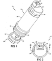
- a multi-port normally open modular valve 10 includes a solenoid portion 12 releasably connected to a polymeric material valve portion 14.
- a thread-in poppet/valve member 16 is releasably connected to modular valve 10 at a free end of the valve portion 14.
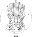
- An end cover 18 is attached to solenoid portion 12 which provides a connecting port 20 having multiple electrical connectors 22, 24 providing electrical power to operate solenoid portion 12.
- the solenoid portion 12 includes a solenoid can 26 which houses a solenoid assembly shown and described in reference to FIG. 2 .
- the valve portion 14 is provided with a first seal member 28 and a second seal member 30 such as O-rings or D-rings.
- the first and second seal members 28, 30 are oppositely positioned about a valve inlet port 32 and will be functionally further described in reference to FIG. 6 .
- modular valve 10 can include opposed end cover flats 34, 36 to assist in installation of modular valve 10.
- the electrical connectors 22, 24 are axially aligned with respect to the solenoid portion 12 such that electrical connection to modular valve 10 can be made within the space envelope of end cover 18. This minimizes the space envelope of modular valve 10 to maximize its side-to-side alignment with multiple other modular valves 10 in a configuration such as in a manifold assembly, shown and described in greater detail in reference to FIG. 6 .
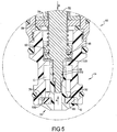
- the components of a solenoid assembly 37 within the solenoid portion 12 include a solenoid coil 38 which is contained in a bobbin 40.
- the solenoid coil 38 When energized, the solenoid coil 38 creates a magnetic field acting through an axially adjustable but normally stationary pole piece 42.
- Pole piece 42 includes a threaded end 44 which is engaged with a threaded aperture 45 of a solenoid can 26, allowing the axial position of pole piece 42 to be manually adjusted by rotation of pole piece 42.
- Pole piece 42 can also include an axial bore 48 providing a vent path through pole piece 42.
- a clearance gap 50 is provided between pole piece 42 and a combination armature/valve member 52 with modular valve 10 in a normally open position shown.
- clearance gap 50 allows armature/valve member 52 to displace from the normally open position to a closed position.
- Both armature/valve member 52 and pole piece 42 are coaxially aligned with and independently displaced with respect to a longitudinal central axis 54 of modular valve 10.
- the magnetic field when created by energizing solenoid coil 38 acts through pole piece 42 to axially displace armature/valve member 52 in a first direction "A" from its normally open downwardly displaced position shown, coaxial with respect to the longitudinal central axis 54, to close modular valve 10. Continuous operation of solenoid coil 38 is therefore required to maintain modular valve 10 in the valve closed position.
- Armature/valve member 52 is slidably guided within a cylinder sleeve 56 positioned within bobbin 40.
- a flange 58 is integrally connected to and is transversely oriented with respect to cylinder sleeve 56.
- Flange 58 is captured between a bobbin end wall 60 and a resilient material seal member 62 such as an O-ring.
- An end seal member 66 such as an O-ring or D-ring is also provided at an outwardly extending body flange 68, whose function will be described in reference to FIG. 6 .
- First body end 64 of valve portion 14 is releasably engaged to solenoid can 26 using a threaded connection 70.
- the first and second seal members 28, 30 are individually retained in first and second slots 72, 74 created at opposite ends of valve portion 14.
- First slot 72 is created in first body end 64 and second slot 74 is created in a second body end 76.
- a biasing member 78 such as a compression spring in direct contact against flange 58 normally provides a biasing force acting in a second direction "B" opposite to first direction "A", which holds the armature/valve member 52 in a normally open position shown.
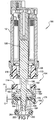
- Armature/valve member 52 includes a valve member portion 80 positioned predominantly within valve portion 14 which is threadably coupled to a tubular portion 82 of thread-in poppet/valve member 16.
- valve portion 14 is made of a polymeric material, reducing both a weight and a cost of modular valve 10.
- Tubular portion 82 and valve member portion 80 are each positioned in a fluid passage 84 of valve portion 14 and are therefore exposed to a fluid such as water, air, or pneumatic fluid controlled by operation of modular valve 10.
- valve ring 86 is retained between a first ring retainer 88 and a second ring retainer 89 both outwardly radially extending integral portions of thread-in poppet/valve member 16.
- Valve ring 86 is used in a valve closed position (shown in FIG. 5 ) to isolate fluid in a valve inlet port "C” from a valve outlet port "D". In the valve open position shown, fluid in valve inlet port "C” is in communication with valve outlet port "D".
- the biasing member 78 is received concentrically about armature/valve member 52 and is in direct contact at a first end with a flange face 90 of flange 58, and at a second end with a piston 92.
- Piston 92 is an integral portion of armature/valve member 52 which is slidably received in a piston cylinder portion 94 of valve portion 14, and slidably displaces in each of the first and second directions "A" and "B".
- the biasing force of biasing member 78 normally acts to displace piston 92 and thereby armature/valve member 52 in the second direction "B".
- a resilient material seal member 96 is provided in a seal ring 98 of piston 92 which is in sliding contact with a bore wall 100 of piston cylinder portion 94 to prevent fluid present in inlet port "C" from reaching the solenoid components of modular valve 10 contained in solenoid can 26.
- an end face 102 of inwardly extending wall 104 of valve portion 14 directly contacts is seated against a compressible seal 103 seated on piston 92.
- An open passage 106 created through wall 104 provides clearance for a rod portion 108 of armature/valve member 52 to extend into inlet port "C".
- the rod portion 108 has a diameter "E” which is sized to slidably fit within a cylindrical tube portion 110 of thread-in poppet/valve member 16.
- a resilient material seal member 112 such as an O-ring or D-ring is provided in a receiving slot 113 created in circular rod portion 108 which provides a fluid boundary seal against an inner wall 114 of an inner bore 115 of cylindrical tube portion 110. Seal member 112 thereby acts to prevent fluid present in inlet port "C” from flowing out of modular valve 10 via inner bore 115.
- the cylindrical tube portion 110 of thread-in poppet/valve member 16 is sized to slidably fit within a smallest diameter portion 116 of inlet port "C”.
- the armature/valve member 52 further includes an end shank 118 having male threads 120 created thereon.
- the male threads 120 are mated with female threads 122 provided in an internal threaded portion 124 of thread-in poppet/valve member 16.
- the longitudinal position of thread-in poppet/valve member 16 with respect to longitudinal central axis 54 can be adjusted by axial rotation of thread-in poppet/valve member 16 with respect to male threads 120.
- valve ring 86 is held in position on thread-in poppet/valve member 16 by direct contact with a flange face 125 of an end flange 126 integrally provided with thread-in poppet/valve member 16 and oppositely by direct contact with a ring face 128 of second retainer ring 89 also integrally provided with thread-in poppet/valve member 16.
- the valve ring 86 is therefore retained between end flange 126 and ring face 128 as armature/valve member 52 displaces in the first and second directions "A", "B".
- valve armature/valve member 52 In the valve normally open position shown, the piston 92 of armature/valve member 52 is maintained in direct contact with compressible seal 103 by the biasing force of biasing member 78. This biasing action positions a flat contact surface 130 of valve ring 86 at a seat clearance distance "F" away from a valve seat surface 132 created in valve portion 14. A fluid flow passage 134 is thereby opened between valve inlet port "C” and an outlet passage 136 defining valve outlet port "D".
- the seat clearance distance "F” is adjustable to increase or decrease seat clearance distance "F” by axial rotation of thread-in poppet/valve member 16 with respect to male threads 120 of armature/valve member 52.
- a valve opening/closing time and/or a valve stroke is also controlled by the seat clearance distance "F". Because thread-in poppet/valve member 16 is accessible to an operator of modular valve 10, adjustment of the seat clearance distance "F” is provided any time the modular valve 10 is not in an installed position.
- thread-in poppet/valve member 16 can be axially adjusted in the first direction "A" to accommodate the wear, or removed in the second direction "B" coaxial to longitudinal central axis 54 and replaced by a new thread-in poppet/valve member 16 or with a new valve ring 86 by displacement in first direction "A".
- modular valve 10 is shown in a valve closed position reached when solenoid coil 38 is energized thereby pulling armature/valve member 52 in the first direction "A", and simultaneously compressing biasing member 78.
- Inwardly extended wall 104 displaces away from contact with compressible seal 103.
- Valve inlet port “C” is isolated from valve outlet port “D” when the flat contact surface 130 of valve ring 86 directly contacts the valve seat surface 132 created in valve portion 14.
- modular valve 10 is held in the valve closed position as long as the solenoid coil 38 is energized.
- biasing force of biasing member 78 returns the armature/valve member 52 and thread-in poppet/valve member 16 in the second direction "B" to the valve open position shown in FIGS. 3-4 .
- a two-way version of modular valve 10 is shown with modular valve 10 installed in a manifold 140.
- Modular valve 10 is received through an aperture of and retained by a hold down plate 142.
- Hold down plate 142 directly contacts manifold 140 and partially compresses end seal member 66, thereby providing a biasing force holding modular valve 10 in the fully installed position shown.
- the valve portion 14 is received in contact with a bore wall 144 of a main cavity 146 of manifold 140 and sealed therein by first seal member 28.
- the second body end 76 of valve portion 14 is slidably received in contact with a bore wall 148 of a second cavity 150 of manifold 140 and sealed by second seal member 30.
- valve portion 14 directly contacts an end wall 154 of second cavity 150, fixing the installed position of modular valve 10.
- the thread-in poppet/valve member 16 is positioned within a flow passage 156 of manifold 140 and is free to axially displace therein.
- a three-way version of a normally open modular valve 162 includes many of the same solenoid components as modular valve 10.
- the components of the solenoid assembly within the solenoid portion 12' are substantially identical and are therefore not further discussed herein.
- a polymeric material valve portion 164 is threadably connected to solenoid portion 12'.
- a clearance gap similar to clearance gap 50 is similarly provided between the pole piece and a combination armature/valve member 166 with modular valve 162 in a normally open position shown. The clearance provided by the clearance gap allows armature/valve member 166 to displace from the normally open position to a closed position.
- Armature/valve member 166 is normally biased similar to armature/valve member 52 using a biasing member 168 positioned in direct contact with an integral, radially extending piston 170 of armature/valve member 166.
- Piston 170 is slidably guided within an upper or first body portion 172 of valve portion 164.
- a lower or second body portion 174 is an integral extension of first body portion 172, and further includes a body end portion 176.
- a cartridge assembly 178 is releasably connected to body end portion 176.
- Cartridge assembly 178 includes a polymeric material snap-in cartridge portion 180 that integrally includes opposed first and second barbs 182, 184 that initially deflect upon installation into body end portion 176 and then snap outwardly to engage body end portion 176.
- a clearance "G” is provided between the snap-in portion 180 and body end portion 176 due to the biasing force of biasing member 168. Clearance "G” is substantially eliminated when modular valve 168 is installed such as in a manifold as described in reference to FIG. 8 .
- Armature/valve member 166 further includes a rod portion 186 extending integrally from piston 170, from which a first radial flange 188 outwardly extends. A resilient material first valve ring 190 is retained by radial flange 188. In the valve open position shown, first valve ring 190 is separated by a ring clearance "H" from a first seat surface 192 created in second body portion 174. Armature/valve member 166 also includes a valve member portion 194 which is functionally similar to valve member portion 80, positioned predominantly within valve portion 164 which includes a male threaded end shank 196 threadably coupled to an internally threaded tubular portion 198 of a thread-in poppet/valve member portion 200 of cartridge assembly 178.
- the snap-in cartridge portion 180 is made of a polymeric material, reducing both a weight and a cost of modular valve 10.
- a seal member 202 such as an O-ring or a D-ring is provided with thread-in poppet/valve member portion 200 to seal against a cylinder end 204 of snap-in cartridge portion 180 when thread-in poppet/valve member 200 is slidably received within snap-in cartridge portion 180.
- Poppet/valve member 200 additionally includes a second radial flange 205 which supports a resilient material second valve ring 206. In the valve open position, second valve ring 206 is seated against a second seat surface 208 created in snap-in cartridge portion 180.
- the male threaded end shank 196 threadably coupled to internally threaded tubular portion 198 of thread-in poppet/valve member portion 200 allows the thread-in poppet/valve member 200 to be axially adjusted by rotation of thread-in poppet/valve member 200.
- the valve throw or ring clearance "H" can thereby be adjusted with modular valve 162 in the assembled, but un-installed condition.
- modular valve 162 in a typical installation, the three-way version of modular valve 162 is shown with modular valve 162 installed in a manifold 210.
- Modular valve 162 is received through an aperture of and retained by a hold down plate 212.
- Hold down plate 212 directly contacts manifold 210 and partially compresses end seal member 66', thereby providing a biasing force holding modular valve 162 in the fully installed position shown.
- Installation of modular valve 162 is otherwise substantially similar to the installation of modular valve 10 in manifold 140.
- a free end of valve portion 164 directly contacts an end wall of a second cavity of manifold 210, fixing the installed position of modular valve 162.
- the thread-in poppet/valve member 200 and the snap-in cartridge portion 180 are positioned within a flow passage of manifold 210 and the thread-in poppet/valve member 200 is adjustable to axially displace therein.
- the manifold 210 is provided with a vent passage 220 aligned with poppet/valve member 20 which is open to atmosphere.
- the exhaust port “K” is in communication with an exhaust connecting port 216, which are isolated from the inlet port “J” and outlet port “L” in the normally open valve position.
- Modular valve 162 may also be used in the normally closed position, by using port “J” as the exhaust port and using port “K” as the inlet port.
- Example embodiments are provided so that this disclosure will be thorough, and will fully convey the scope to those who are skilled in the art. Numerous specific details are set forth such as examples of specific components, devices, and methods, to provide a thorough understanding of embodiments of the present disclosure. It will be apparent to those skilled in the art that specific details need not be employed, that example embodiments may be embodied in many different forms and that neither should be construed to limit the scope of the disclosure, which is limited only by the appended claims. In some example embodiments, well-known processes, well-known device structures, and well-known technologies are not described in detail.
- first, second, third, etc. may be used herein to describe various elements, components, regions, layers and/or sections, these elements, components, regions, layers and/or sections should not be limited by these terms. These terms may be only used to distinguish one element, component, region, layer or section from another region, layer or section. Terms such as “first,” “second,” and other numerical terms when used herein do not imply a sequence or order unless clearly indicated by the context. Thus, a first element, component, region, layer or section discussed below could be termed a second element, component, region, layer or section without departing from the teachings of the example embodiments.
- spatially relative terms such as “inner,” “outer,” “beneath,” “below,” “lower,” “above,” “upper,” and the like, may be used herein for ease of description to describe one element or feature's relationship to another element(s) or feature(s) as illustrated in the figures.
- Spatially relative terms may be intended to encompass different orientations of the device in use or operation in addition to the orientation depicted in the figures. For example, if the device in the figures is turned over, elements described as “below” or “beneath” other elements or features would then be oriented “above” the other elements or features.
- the example term “below” can encompass both an orientation of above and below.
- the device may be otherwise oriented (rotated 90 degrees or at other orientations) and the spatially relative descriptors used herein interpreted accordingly.
Landscapes
- Engineering & Computer Science (AREA)
- General Engineering & Computer Science (AREA)
- Mechanical Engineering (AREA)
- Physics & Mathematics (AREA)
- Electromagnetism (AREA)
- Magnetically Actuated Valves (AREA)
- Lift Valve (AREA)
- Multiple-Way Valves (AREA)
- Electromagnets (AREA)
Claims (13)
- Soupape modulaire à solénoïde normalement ouverte (10, 162), comprenant :un corps de solénoïde (12, 12') recevant à la fois une bobine (38) et une pièce polaire (42) ;une partie corps de soupape (14, 164) reliée au corps de solénoïde ;un organe soupape/armature (52, 166) comprenant une tige d'extrémité filetée (118, 196) positionnée dans la partie corps de soupape ;un organe soupape/clapet fileté (16, 200) comportant :une partie filetée (124, 198) engageant la tige d'extrémité filetée afin de retenir l'organe soupape/clapet fileté sur l'organe soupape/armature ; etune partie tubulaire cylindrique (110) recevant, en coulissement, une partie tige (108, 186) de l'organe soupape/armature, la partie tige étant positionnée à proximité de la tige d'extrémité et comprenant un organe d'étanchéité (112) en contact, en coulissement, avec une paroi interne (114) de la partie tubulaire cylindrique empêchant le fluide dans la soupape modulaire de passer au-delà de la tige d'extrémité filetée de l'organe soupape/armature ;une bague de soupape (86, 190) retenue sur l'organe soupape/clapet fileté ou l'organe soupape/armature ; etun organe de sollicitation (78, 168) opérant à l'encontre de l'organe soupape/armature afin de solliciter normalement la bague de soupape hors de contact avec une surface de siège de soupape (132, 192) créée dans la partie corps de soupape de manière à définir une position de soupape normalement ouverte de la soupape modulaire.
- Soupape modulaire à solénoïde normalement ouverte (10, 162) selon la revendication 1, dans laquelle le corps de solénoïde (12, 12') comprend, en outre, une bobine (40) supportant la bobine (38) et ayant la pièce polaire (42) reçue en coulissement dans la bobine.
- Soupape modulaire à solénoïde normalement ouverte (10, 162) selon la revendication 2, dans laquelle la pièce polaire (42) est positionnée en mouvement dans la bobine (40) et comprend, en outre, une extrémité filetée (44) engageant la pièce polaire sur le corps de solénoïde (12, 12'), permettant à une position axiale de la pièce polaire d'être sélectionnée par rotation de la pièce polaire par rapport à l'extrémité filetée, ce qui crée un jeu (50) entre la pièce polaire et l'organe soupape/armature (52, 166) définissant une longueur de course de soupape.
- Soupape modulaire à solénoïde normalement ouverte (10, 162) selon l'une quelconque des revendications précédentes, dans laquelle l'organe soupape/armature (52, 166) est disposé en coulissement à la fois dans le corps de solénoïde (12, 12') et dans la partie corps de soupape (14, 164) et est déplacé vers la pièce polaire (42) par un champ magnétique créé par la bobine (38) lorsque la bobine est excitée et opérant à travers l'organe soupape/armature et la pièce polaire, ce qui comprime l'organe de sollicitation (78, 168) jusqu'à ce que la bague de soupape (86, 190) entre en contact avec la surface de siège de soupape (132, 192) définissant une position fermée de soupape.
- Soupape modulaire à solénoïde normalement ouverte (10) selon l'une quelconque des revendications précédentes, dans laquelle la soupape modulaire est une soupape à deux voies.
- Soupape modulaire à solénoïde normalement ouverte (162) selon l'une quelconque des revendications 1 à 4, dans laquelle la soupape modulaire est une soupape à trois voies ayant l'organe soupape/clapet fileté (200) comportant une partie cartouche encliquetée (180) et une partie cartouche filetée.
- Soupape modulaire à solénoïde normalement ouverte (162) selon la revendication 6, dans laquelle la partie cartouche encliquetée (180) comprend des première et seconde pointes opposées (182, 184) engageant la partie cartouche encliquetée sur la partie corps de soupape (164).
- Soupape modulaire à solénoïde normalement ouverte (10, 162) selon l'une quelconque des revendications précédentes, comprenant, en outre, un collecteur (140, 210) comportant un alésage de collecteur (146, 150) recevant la soupape modulaire et une face d'extrémité d'alésage modulaire, la partie corps de soupape (14, 164) étant en contact direct avec une face d'extrémité de corps de siège (154) de la face d'extrémité d'alésage de collecteur.
- Soupape modulaire à solénoïde normalement ouverte (10) selon la revendication 1, dans laquelle l'organe soupape/clapet fileté (16) comprend des premier et second organes de retenue de bague (88, 89) ayant la bague de soupape (86) positionnée entre les premier et second organes de retenue de bague.
- Soupape modulaire à solénoïde normalement ouverte (10, 162) selon l'une quelconque des revendications précédentes, dans laquelle, dans la position normalement ouverte, la bague de soupape (86, 190) est espacée de la surface de siège de soupape (132, 192) définissant une distance de jeu de siège, la distance de jeu de siège étant réglable par rotation de l'organe soupape/clapet fileté (16, 200) par rapport à la tige d'extrémité (118, 196) de l'organe soupape/armature (52, 166) servant à déplacer axialement l'organe soupape/clapet fileté.
- Soupape modulaire à solénoïde normalement ouverte (10, 162) selon l'une quelconque des revendications précédentes, dans laquelle l'organe soupape/armature (52, 166) comprend un piston (92, 170) reçu en coulissement dans une partie cylindrique de piston (94, 172) de la partie corps de soupape (14, 164).
- Soupape modulaire à solénoïde normalement ouverte (10, 162) selon la revendication 11, dans laquelle un organe d'étanchéité de soupape (96, 98) est supporté sur le piston (92, 170) en contact glissant avec une paroi d'alésage (100) de la partie cylindrique de piston (94, 172), l'organe d'étanchéité de soupape isolant un fluide dans la soupape modulaire du corps de solénoïde (12, 12').
- Soupape modulaire à solénoïde normalement ouverte (10, 162) selon la revendication 11 ou 12, dans laquelle l'organe de sollicitation (78, 168) est positionné entre, et en contact avec, à la fois le piston (92, 170) et un rebord (58) d'un manchon de cylindre (56) guidant axialement l'organe soupape/armature (52, 166).
Priority Applications (1)
| Application Number | Priority Date | Filing Date | Title |
|---|---|---|---|
| PL13196545T PL2746627T3 (pl) | 2012-12-21 | 2013-12-10 | Wielodrożny normalnie otwarty zawór modułowy z gwintowanym gniazdem |
Applications Claiming Priority (1)
| Application Number | Priority Date | Filing Date | Title |
|---|---|---|---|
| US13/724,455 US9074699B2 (en) | 2012-12-21 | 2012-12-21 | Multi-port normally open modular valve with thread-in seat |
Publications (2)
| Publication Number | Publication Date |
|---|---|
| EP2746627A1 EP2746627A1 (fr) | 2014-06-25 |
| EP2746627B1 true EP2746627B1 (fr) | 2018-04-04 |
Family
ID=49916810
Family Applications (1)
| Application Number | Title | Priority Date | Filing Date |
|---|---|---|---|
| EP13196545.1A Not-in-force EP2746627B1 (fr) | 2012-12-21 | 2013-12-10 | Soupape modulaire normalement ouverte multiport avec siège fileté |
Country Status (14)
| Country | Link |
|---|---|
| US (1) | US9074699B2 (fr) |
| EP (1) | EP2746627B1 (fr) |
| JP (1) | JP6227998B2 (fr) |
| KR (1) | KR101871697B1 (fr) |
| CN (1) | CN103883745B (fr) |
| AU (1) | AU2013270473B2 (fr) |
| CA (1) | CA2837070C (fr) |
| ES (1) | ES2671751T3 (fr) |
| MX (1) | MX338858B (fr) |
| NZ (1) | NZ619339A (fr) |
| PL (1) | PL2746627T3 (fr) |
| PT (1) | PT2746627T (fr) |
| TW (1) | TWI588389B (fr) |
| ZA (1) | ZA201309656B (fr) |
Families Citing this family (21)
| Publication number | Priority date | Publication date | Assignee | Title |
|---|---|---|---|---|
| IL233615A (en) * | 2014-07-10 | 2016-02-29 | Ettem Eng S A Ltd | Method and devices for discharging pollutants from a sealing chamber |
| US9631735B2 (en) * | 2014-11-17 | 2017-04-25 | Flextronics Ap, Llc | Integration of magnet in solenoid vent path |
| DE102015007694A1 (de) * | 2015-06-17 | 2016-12-22 | Andreas Stihl Ag & Co. Kg | Elektromagnetisches Ventil für ein Kraftstoffsystem |
| US10194678B2 (en) | 2015-09-09 | 2019-02-05 | Taylor Commercial Foodservice Inc. | Frozen beverage machine valving |
| DE102016100604A1 (de) * | 2016-01-14 | 2017-07-20 | Eto Magnetic Gmbh | Elektromagnetventil und Verwendung eines solchen |
| TWI601900B (zh) * | 2016-06-16 | 2017-10-11 | Piezoelectric controlled pilot operated valve | |
| US10871242B2 (en) | 2016-06-23 | 2020-12-22 | Rain Bird Corporation | Solenoid and method of manufacture |
| CN106352147A (zh) * | 2016-10-10 | 2017-01-25 | 合肥协力液压科技有限公司 | 一种电磁叠加阀 |
| US10578226B2 (en) * | 2016-12-22 | 2020-03-03 | Mac Valves, Inc. | Valve with two-piece adjustable can with integral pole piece |
| CN107246496B (zh) * | 2017-03-29 | 2024-03-08 | 厦门建霖健康家居股份有限公司 | 一种开关装置 |
| US10980120B2 (en) | 2017-06-15 | 2021-04-13 | Rain Bird Corporation | Compact printed circuit board |
| US10753498B2 (en) * | 2018-01-25 | 2020-08-25 | Mac Valves, Inc. | Flow-through liquid valve |
| US11503782B2 (en) | 2018-04-11 | 2022-11-22 | Rain Bird Corporation | Smart drip irrigation emitter |
| CN108413076B (zh) * | 2018-05-09 | 2024-10-01 | 乔登卫浴(江门)有限公司 | 一种整体式直动分水阀 |
| CN214425117U (zh) * | 2020-04-07 | 2021-10-19 | 奥达尔(香港)有限公司 | 用于流体泵的阀 |
| US11721465B2 (en) | 2020-04-24 | 2023-08-08 | Rain Bird Corporation | Solenoid apparatus and methods of assembly |
| JP7523249B2 (ja) * | 2020-04-27 | 2024-07-26 | 川崎重工業株式会社 | 弁装置 |
| US11293564B2 (en) * | 2020-06-05 | 2022-04-05 | Automatic Switch Company | Valve silencing choke |
| EP4237717A4 (fr) * | 2020-10-30 | 2024-10-09 | Rotex Automation Ltd | Soupape pneumatique à joints flexibles |
| CN113932040B (zh) * | 2021-10-16 | 2024-04-12 | 涌镇液压机械(上海)有限公司 | 控制注塑机开合模的比例阀 |
| CN114458816B (zh) * | 2022-01-10 | 2024-04-26 | 宁波市安利特机械有限公司 | 一种瓶内减压自锁一体式电磁阀 |
Family Cites Families (19)
| Publication number | Priority date | Publication date | Assignee | Title |
|---|---|---|---|---|
| US1049845A (en) * | 1910-09-15 | 1913-01-07 | Geissinger Regulator Company | Electromagnetic valve. |
| US1389056A (en) * | 1916-10-06 | 1921-08-30 | Edwin B Lane | Electromagnet and valve |
| US3552714A (en) * | 1968-05-08 | 1971-01-05 | Manville Mfg Corp | Torque free valve assembly |
| CA1021225A (fr) * | 1974-06-28 | 1977-11-22 | General Signal Corporation | Vanne a ouverture rapide |
| DE3219833C2 (de) * | 1982-05-26 | 1985-12-19 | Bosch-Siemens Hausgeräte GmbH, 7000 Stuttgart | Ventil im Hartwasserweg zum Spülbehälter von Geschirrspülmaschinen |
| US4530486A (en) * | 1983-02-09 | 1985-07-23 | City Of Hope National Medical Center | Valve |
| US4598736A (en) * | 1984-12-03 | 1986-07-08 | Chorkey William J | Solenoid operated valve with balancing means |
| US5413308A (en) * | 1993-09-03 | 1995-05-09 | The Horton Company | Fail-open solenoid actuated valve |
| US5474107A (en) * | 1993-09-03 | 1995-12-12 | The Horton Company | Fail-open solenoid actuated valve |
| US6631881B2 (en) * | 2000-08-08 | 2003-10-14 | Siemens Automotive Inc. | Single-stage fuel tank pressure control valve |
| JP3857094B2 (ja) * | 2001-09-04 | 2006-12-13 | Smc株式会社 | 電磁弁 |
| US20040036048A1 (en) * | 2002-08-20 | 2004-02-26 | Petersen Peter Waygaard | Gaseous fuel injector |
| JP2004108518A (ja) * | 2002-09-19 | 2004-04-08 | Aisin Seiki Co Ltd | 流体バルブ装置 |
| JP4439822B2 (ja) * | 2003-02-14 | 2010-03-24 | 三菱電機株式会社 | 電磁弁 |
| JP2006153215A (ja) * | 2004-11-30 | 2006-06-15 | Keihin Corp | 燃料電池用電磁弁 |
| US8151824B2 (en) * | 2007-04-05 | 2012-04-10 | Mac Valves, Inc. | Balanced solenoid valve |
| US8167000B2 (en) * | 2007-04-05 | 2012-05-01 | Mac Valves, Inc. | Balanced solenoid valve |
| JP2010138941A (ja) * | 2008-12-09 | 2010-06-24 | Aisin Seiki Co Ltd | モータ搭載バルブ |
| US9010373B2 (en) * | 2010-09-09 | 2015-04-21 | Mac Valves, Inc. | Pressure balanced valve with diaphragm valve member end seal |
-
2012
- 2012-12-21 US US13/724,455 patent/US9074699B2/en active Active
-
2013
- 2013-12-10 ES ES13196545.1T patent/ES2671751T3/es active Active
- 2013-12-10 PL PL13196545T patent/PL2746627T3/pl unknown
- 2013-12-10 AU AU2013270473A patent/AU2013270473B2/en not_active Ceased
- 2013-12-10 EP EP13196545.1A patent/EP2746627B1/fr not_active Not-in-force
- 2013-12-10 PT PT131965451T patent/PT2746627T/pt unknown
- 2013-12-17 CA CA2837070A patent/CA2837070C/fr not_active Expired - Fee Related
- 2013-12-17 MX MX2013014917A patent/MX338858B/es active IP Right Grant
- 2013-12-19 TW TW102147267A patent/TWI588389B/zh active
- 2013-12-19 JP JP2013262203A patent/JP6227998B2/ja not_active Expired - Fee Related
- 2013-12-20 CN CN201310713669.0A patent/CN103883745B/zh not_active Expired - Fee Related
- 2013-12-20 ZA ZA2013/09656A patent/ZA201309656B/en unknown
- 2013-12-20 NZ NZ619339A patent/NZ619339A/en not_active IP Right Cessation
- 2013-12-20 KR KR1020130160584A patent/KR101871697B1/ko active IP Right Grant
Non-Patent Citations (1)
| Title |
|---|
| None * |
Also Published As
| Publication number | Publication date |
|---|---|
| CN103883745B (zh) | 2018-09-18 |
| JP2014122701A (ja) | 2014-07-03 |
| US20140175312A1 (en) | 2014-06-26 |
| ES2671751T3 (es) | 2018-06-08 |
| CN103883745A (zh) | 2014-06-25 |
| JP6227998B2 (ja) | 2017-11-08 |
| KR101871697B1 (ko) | 2018-06-27 |
| KR20140081742A (ko) | 2014-07-01 |
| CA2837070C (fr) | 2017-07-18 |
| ZA201309656B (en) | 2015-04-29 |
| CA2837070A1 (fr) | 2014-06-21 |
| AU2013270473B2 (en) | 2016-11-24 |
| AU2013270473A1 (en) | 2014-07-10 |
| MX338858B (es) | 2016-05-03 |
| US9074699B2 (en) | 2015-07-07 |
| EP2746627A1 (fr) | 2014-06-25 |
| PL2746627T3 (pl) | 2018-08-31 |
| TWI588389B (zh) | 2017-06-21 |
| NZ619339A (en) | 2015-08-28 |
| TW201433720A (zh) | 2014-09-01 |
| MX2013014917A (es) | 2014-08-06 |
| PT2746627T (pt) | 2018-06-21 |
Similar Documents
| Publication | Publication Date | Title |
|---|---|---|
| EP2746627B1 (fr) | Soupape modulaire normalement ouverte multiport avec siège fileté | |
| CA2838116C (fr) | Soupape modulaire a orifices multiples a logement d'encliquetage | |
| EP2614278B1 (fr) | Vanne à pression autorégularisée avec dispositif d'étanchéité d'extrémité d'élément de vanne à diaphragme | |
| CA3011059C (fr) | Robinet a membrane | |
| BR102013032835A2 (pt) | válvula modular normalmente aberta de múltiplas portas com roscas no assento | |
| NZ741227A (en) | Diaphragm Valve |
Legal Events
| Date | Code | Title | Description |
|---|---|---|---|
| PUAI | Public reference made under article 153(3) epc to a published international application that has entered the european phase |
Free format text: ORIGINAL CODE: 0009012 |
|
| 17P | Request for examination filed |
Effective date: 20131210 |
|
| AK | Designated contracting states |
Kind code of ref document: A1 Designated state(s): AL AT BE BG CH CY CZ DE DK EE ES FI FR GB GR HR HU IE IS IT LI LT LU LV MC MK MT NL NO PL PT RO RS SE SI SK SM TR |
|
| AX | Request for extension of the european patent |
Extension state: BA ME |
|
| R17P | Request for examination filed (corrected) |
Effective date: 20141223 |
|
| RBV | Designated contracting states (corrected) |
Designated state(s): AL AT BE BG CH CY CZ DE DK EE ES FI FR GB GR HR HU IE IS IT LI LT LU LV MC MK MT NL NO PL PT RO RS SE SI SK SM TR |
|
| REG | Reference to a national code |
Ref country code: DE Ref legal event code: R079 Ref document number: 602013035333 Country of ref document: DE Free format text: PREVIOUS MAIN CLASS: F16K0001340000 Ipc: F16K0031020000 |
|
| RIC1 | Information provided on ipc code assigned before grant |
Ipc: F16K 27/02 20060101ALI20170904BHEP Ipc: F16K 11/044 20060101ALI20170904BHEP Ipc: F16K 1/34 20060101ALI20170904BHEP Ipc: F16K 31/02 20060101AFI20170904BHEP |
|
| GRAP | Despatch of communication of intention to grant a patent |
Free format text: ORIGINAL CODE: EPIDOSNIGR1 |
|
| STAA | Information on the status of an ep patent application or granted ep patent |
Free format text: STATUS: GRANT OF PATENT IS INTENDED |
|
| INTG | Intention to grant announced |
Effective date: 20171020 |
|
| GRAS | Grant fee paid |
Free format text: ORIGINAL CODE: EPIDOSNIGR3 |
|
| GRAA | (expected) grant |
Free format text: ORIGINAL CODE: 0009210 |
|
| STAA | Information on the status of an ep patent application or granted ep patent |
Free format text: STATUS: THE PATENT HAS BEEN GRANTED |
|
| AK | Designated contracting states |
Kind code of ref document: B1 Designated state(s): AL AT BE BG CH CY CZ DE DK EE ES FI FR GB GR HR HU IE IS IT LI LT LU LV MC MK MT NL NO PL PT RO RS SE SI SK SM TR |
|
| REG | Reference to a national code |
Ref country code: GB Ref legal event code: FG4D |
|
| REG | Reference to a national code |
Ref country code: CH Ref legal event code: EP Ref country code: CH Ref legal event code: NV Representative=s name: RIEDERER HASLER AND PARTNER PATENTANWAELTE AG, CH |
|
| REG | Reference to a national code |
Ref country code: AT Ref legal event code: REF Ref document number: 985953 Country of ref document: AT Kind code of ref document: T Effective date: 20180415 |
|
| REG | Reference to a national code |
Ref country code: DE Ref legal event code: R096 Ref document number: 602013035333 Country of ref document: DE |
|
| REG | Reference to a national code |
Ref country code: IE Ref legal event code: FG4D |
|
| REG | Reference to a national code |
Ref country code: ES Ref legal event code: FG2A Ref document number: 2671751 Country of ref document: ES Kind code of ref document: T3 Effective date: 20180608 |
|
| REG | Reference to a national code |
Ref country code: NL Ref legal event code: FP |
|
| REG | Reference to a national code |
Ref country code: PT Ref legal event code: SC4A Ref document number: 2746627 Country of ref document: PT Date of ref document: 20180621 Kind code of ref document: T Free format text: AVAILABILITY OF NATIONAL TRANSLATION Effective date: 20180614 |
|
| REG | Reference to a national code |
Ref country code: SE Ref legal event code: TRGR |
|
| REG | Reference to a national code |
Ref country code: LT Ref legal event code: MG4D |
|
| PG25 | Lapsed in a contracting state [announced via postgrant information from national office to epo] |
Ref country code: FI Free format text: LAPSE BECAUSE OF FAILURE TO SUBMIT A TRANSLATION OF THE DESCRIPTION OR TO PAY THE FEE WITHIN THE PRESCRIBED TIME-LIMIT Effective date: 20180404 Ref country code: NO Free format text: LAPSE BECAUSE OF FAILURE TO SUBMIT A TRANSLATION OF THE DESCRIPTION OR TO PAY THE FEE WITHIN THE PRESCRIBED TIME-LIMIT Effective date: 20180704 Ref country code: BG Free format text: LAPSE BECAUSE OF FAILURE TO SUBMIT A TRANSLATION OF THE DESCRIPTION OR TO PAY THE FEE WITHIN THE PRESCRIBED TIME-LIMIT Effective date: 20180704 Ref country code: AL Free format text: LAPSE BECAUSE OF FAILURE TO SUBMIT A TRANSLATION OF THE DESCRIPTION OR TO PAY THE FEE WITHIN THE PRESCRIBED TIME-LIMIT Effective date: 20180404 Ref country code: LT Free format text: LAPSE BECAUSE OF FAILURE TO SUBMIT A TRANSLATION OF THE DESCRIPTION OR TO PAY THE FEE WITHIN THE PRESCRIBED TIME-LIMIT Effective date: 20180404 |
|
| PG25 | Lapsed in a contracting state [announced via postgrant information from national office to epo] |
Ref country code: RS Free format text: LAPSE BECAUSE OF FAILURE TO SUBMIT A TRANSLATION OF THE DESCRIPTION OR TO PAY THE FEE WITHIN THE PRESCRIBED TIME-LIMIT Effective date: 20180404 Ref country code: HR Free format text: LAPSE BECAUSE OF FAILURE TO SUBMIT A TRANSLATION OF THE DESCRIPTION OR TO PAY THE FEE WITHIN THE PRESCRIBED TIME-LIMIT Effective date: 20180404 Ref country code: LV Free format text: LAPSE BECAUSE OF FAILURE TO SUBMIT A TRANSLATION OF THE DESCRIPTION OR TO PAY THE FEE WITHIN THE PRESCRIBED TIME-LIMIT Effective date: 20180404 |
|
| REG | Reference to a national code |
Ref country code: DE Ref legal event code: R097 Ref document number: 602013035333 Country of ref document: DE |
|
| REG | Reference to a national code |
Ref country code: GR Ref legal event code: EP Ref document number: 20180401646 Country of ref document: GR Effective date: 20190109 |
|
| PG25 | Lapsed in a contracting state [announced via postgrant information from national office to epo] |
Ref country code: SK Free format text: LAPSE BECAUSE OF FAILURE TO SUBMIT A TRANSLATION OF THE DESCRIPTION OR TO PAY THE FEE WITHIN THE PRESCRIBED TIME-LIMIT Effective date: 20180404 Ref country code: RO Free format text: LAPSE BECAUSE OF FAILURE TO SUBMIT A TRANSLATION OF THE DESCRIPTION OR TO PAY THE FEE WITHIN THE PRESCRIBED TIME-LIMIT Effective date: 20180404 Ref country code: DK Free format text: LAPSE BECAUSE OF FAILURE TO SUBMIT A TRANSLATION OF THE DESCRIPTION OR TO PAY THE FEE WITHIN THE PRESCRIBED TIME-LIMIT Effective date: 20180404 Ref country code: EE Free format text: LAPSE BECAUSE OF FAILURE TO SUBMIT A TRANSLATION OF THE DESCRIPTION OR TO PAY THE FEE WITHIN THE PRESCRIBED TIME-LIMIT Effective date: 20180404 |
|
| PLBE | No opposition filed within time limit |
Free format text: ORIGINAL CODE: 0009261 |
|
| STAA | Information on the status of an ep patent application or granted ep patent |
Free format text: STATUS: NO OPPOSITION FILED WITHIN TIME LIMIT |
|
| PG25 | Lapsed in a contracting state [announced via postgrant information from national office to epo] |
Ref country code: SM Free format text: LAPSE BECAUSE OF FAILURE TO SUBMIT A TRANSLATION OF THE DESCRIPTION OR TO PAY THE FEE WITHIN THE PRESCRIBED TIME-LIMIT Effective date: 20180404 |
|
| 26N | No opposition filed |
Effective date: 20190107 |
|
| PG25 | Lapsed in a contracting state [announced via postgrant information from national office to epo] |
Ref country code: SI Free format text: LAPSE BECAUSE OF FAILURE TO SUBMIT A TRANSLATION OF THE DESCRIPTION OR TO PAY THE FEE WITHIN THE PRESCRIBED TIME-LIMIT Effective date: 20180404 |
|
| PG25 | Lapsed in a contracting state [announced via postgrant information from national office to epo] |
Ref country code: MC Free format text: LAPSE BECAUSE OF FAILURE TO SUBMIT A TRANSLATION OF THE DESCRIPTION OR TO PAY THE FEE WITHIN THE PRESCRIBED TIME-LIMIT Effective date: 20180404 Ref country code: LU Free format text: LAPSE BECAUSE OF NON-PAYMENT OF DUE FEES Effective date: 20181210 |
|
| PG25 | Lapsed in a contracting state [announced via postgrant information from national office to epo] |
Ref country code: MT Free format text: LAPSE BECAUSE OF NON-PAYMENT OF DUE FEES Effective date: 20181210 |
|
| PG25 | Lapsed in a contracting state [announced via postgrant information from national office to epo] |
Ref country code: TR Free format text: LAPSE BECAUSE OF FAILURE TO SUBMIT A TRANSLATION OF THE DESCRIPTION OR TO PAY THE FEE WITHIN THE PRESCRIBED TIME-LIMIT Effective date: 20180404 |
|
| PG25 | Lapsed in a contracting state [announced via postgrant information from national office to epo] |
Ref country code: MK Free format text: LAPSE BECAUSE OF NON-PAYMENT OF DUE FEES Effective date: 20180404 Ref country code: HU Free format text: LAPSE BECAUSE OF FAILURE TO SUBMIT A TRANSLATION OF THE DESCRIPTION OR TO PAY THE FEE WITHIN THE PRESCRIBED TIME-LIMIT; INVALID AB INITIO Effective date: 20131210 Ref country code: CY Free format text: LAPSE BECAUSE OF FAILURE TO SUBMIT A TRANSLATION OF THE DESCRIPTION OR TO PAY THE FEE WITHIN THE PRESCRIBED TIME-LIMIT Effective date: 20180404 |
|
| PG25 | Lapsed in a contracting state [announced via postgrant information from national office to epo] |
Ref country code: IS Free format text: LAPSE BECAUSE OF FAILURE TO SUBMIT A TRANSLATION OF THE DESCRIPTION OR TO PAY THE FEE WITHIN THE PRESCRIBED TIME-LIMIT Effective date: 20180804 |
|
| PGFP | Annual fee paid to national office [announced via postgrant information from national office to epo] |
Ref country code: CZ Payment date: 20201125 Year of fee payment: 8 Ref country code: PT Payment date: 20201124 Year of fee payment: 8 Ref country code: SE Payment date: 20201228 Year of fee payment: 8 Ref country code: GB Payment date: 20201228 Year of fee payment: 8 Ref country code: GR Payment date: 20201229 Year of fee payment: 8 Ref country code: FR Payment date: 20201227 Year of fee payment: 8 Ref country code: IE Payment date: 20201228 Year of fee payment: 8 Ref country code: AT Payment date: 20201119 Year of fee payment: 8 |
|
| PGFP | Annual fee paid to national office [announced via postgrant information from national office to epo] |
Ref country code: BE Payment date: 20201228 Year of fee payment: 8 Ref country code: PL Payment date: 20201118 Year of fee payment: 8 |
|
| PGFP | Annual fee paid to national office [announced via postgrant information from national office to epo] |
Ref country code: NL Payment date: 20201226 Year of fee payment: 8 |
|
| PGFP | Annual fee paid to national office [announced via postgrant information from national office to epo] |
Ref country code: CH Payment date: 20210106 Year of fee payment: 8 Ref country code: IT Payment date: 20201221 Year of fee payment: 8 |
|
| PGFP | Annual fee paid to national office [announced via postgrant information from national office to epo] |
Ref country code: ES Payment date: 20210104 Year of fee payment: 8 Ref country code: DE Payment date: 20201229 Year of fee payment: 8 |
|
| REG | Reference to a national code |
Ref country code: AT Ref legal event code: UEP Ref document number: 985953 Country of ref document: AT Kind code of ref document: T Effective date: 20180404 |
|
| REG | Reference to a national code |
Ref country code: DE Ref legal event code: R119 Ref document number: 602013035333 Country of ref document: DE |
|
| PG25 | Lapsed in a contracting state [announced via postgrant information from national office to epo] |
Ref country code: PT Free format text: LAPSE BECAUSE OF NON-PAYMENT OF DUE FEES Effective date: 20220613 Ref country code: CZ Free format text: LAPSE BECAUSE OF NON-PAYMENT OF DUE FEES Effective date: 20211210 |
|
| REG | Reference to a national code |
Ref country code: CH Ref legal event code: PL |
|
| REG | Reference to a national code |
Ref country code: SE Ref legal event code: EUG |
|
| REG | Reference to a national code |
Ref country code: NL Ref legal event code: MM Effective date: 20220101 |
|
| REG | Reference to a national code |
Ref country code: AT Ref legal event code: MM01 Ref document number: 985953 Country of ref document: AT Kind code of ref document: T Effective date: 20211210 |
|
| GBPC | Gb: european patent ceased through non-payment of renewal fee |
Effective date: 20211210 |
|
| REG | Reference to a national code |
Ref country code: BE Ref legal event code: MM Effective date: 20211231 |
|
| PG25 | Lapsed in a contracting state [announced via postgrant information from national office to epo] |
Ref country code: NL Free format text: LAPSE BECAUSE OF NON-PAYMENT OF DUE FEES Effective date: 20220101 |
|
| PG25 | Lapsed in a contracting state [announced via postgrant information from national office to epo] |
Ref country code: SE Free format text: LAPSE BECAUSE OF NON-PAYMENT OF DUE FEES Effective date: 20211211 Ref country code: IE Free format text: LAPSE BECAUSE OF NON-PAYMENT OF DUE FEES Effective date: 20211210 Ref country code: GR Free format text: LAPSE BECAUSE OF NON-PAYMENT OF DUE FEES Effective date: 20220706 Ref country code: GB Free format text: LAPSE BECAUSE OF NON-PAYMENT OF DUE FEES Effective date: 20211210 Ref country code: DE Free format text: LAPSE BECAUSE OF NON-PAYMENT OF DUE FEES Effective date: 20220701 Ref country code: AT Free format text: LAPSE BECAUSE OF NON-PAYMENT OF DUE FEES Effective date: 20211210 |
|
| PG25 | Lapsed in a contracting state [announced via postgrant information from national office to epo] |
Ref country code: FR Free format text: LAPSE BECAUSE OF NON-PAYMENT OF DUE FEES Effective date: 20211231 Ref country code: BE Free format text: LAPSE BECAUSE OF NON-PAYMENT OF DUE FEES Effective date: 20211231 |
|
| PG25 | Lapsed in a contracting state [announced via postgrant information from national office to epo] |
Ref country code: LI Free format text: LAPSE BECAUSE OF NON-PAYMENT OF DUE FEES Effective date: 20211231 Ref country code: CH Free format text: LAPSE BECAUSE OF NON-PAYMENT OF DUE FEES Effective date: 20211231 |
|
| PG25 | Lapsed in a contracting state [announced via postgrant information from national office to epo] |
Ref country code: IT Free format text: LAPSE BECAUSE OF NON-PAYMENT OF DUE FEES Effective date: 20211210 |
|
| REG | Reference to a national code |
Ref country code: ES Ref legal event code: FD2A Effective date: 20230303 |
|
| PG25 | Lapsed in a contracting state [announced via postgrant information from national office to epo] |
Ref country code: ES Free format text: LAPSE BECAUSE OF NON-PAYMENT OF DUE FEES Effective date: 20211211 |
|
| PG25 | Lapsed in a contracting state [announced via postgrant information from national office to epo] |
Ref country code: PL Free format text: LAPSE BECAUSE OF NON-PAYMENT OF DUE FEES Effective date: 20211210 |