EP2746180B2 - Gable top container - Google Patents
Gable top container Download PDFInfo
- Publication number
- EP2746180B2 EP2746180B2 EP14000874.9A EP14000874A EP2746180B2 EP 2746180 B2 EP2746180 B2 EP 2746180B2 EP 14000874 A EP14000874 A EP 14000874A EP 2746180 B2 EP2746180 B2 EP 2746180B2
- Authority
- EP
- European Patent Office
- Prior art keywords
- obturating
- weakness
- panel
- parts
- boundary
- Prior art date
- Legal status (The legal status is an assumption and is not a legal conclusion. Google has not performed a legal analysis and makes no representation as to the accuracy of the status listed.)
- Active
Links
- 238000007789 sealing Methods 0.000 claims description 36
- 230000007704 transition Effects 0.000 claims description 26
- 239000000463 material Substances 0.000 claims description 6
- 239000011087 paperboard Substances 0.000 claims description 3
- 239000004033 plastic Substances 0.000 claims description 3
- 229920003023 plastic Polymers 0.000 claims description 3
- 238000005336 cracking Methods 0.000 description 5
- 239000002648 laminated material Substances 0.000 description 5
- 239000005022 packaging material Substances 0.000 description 5
- 230000004888 barrier function Effects 0.000 description 3
- 230000001154 acute effect Effects 0.000 description 2
- 238000000034 method Methods 0.000 description 2
- QVGXLLKOCUKJST-UHFFFAOYSA-N atomic oxygen Chemical compound [O] QVGXLLKOCUKJST-UHFFFAOYSA-N 0.000 description 1
- 238000005452 bending Methods 0.000 description 1
- 230000008901 benefit Effects 0.000 description 1
- 230000015572 biosynthetic process Effects 0.000 description 1
- 235000015203 fruit juice Nutrition 0.000 description 1
- 239000007789 gas Substances 0.000 description 1
- 238000004519 manufacturing process Methods 0.000 description 1
- 235000013336 milk Nutrition 0.000 description 1
- 239000008267 milk Substances 0.000 description 1
- 210000004080 milk Anatomy 0.000 description 1
- 230000004048 modification Effects 0.000 description 1
- 238000012986 modification Methods 0.000 description 1
- 239000001301 oxygen Substances 0.000 description 1
- 229910052760 oxygen Inorganic materials 0.000 description 1
- 238000004806 packaging method and process Methods 0.000 description 1
- 239000000123 paper Substances 0.000 description 1
- 230000008569 process Effects 0.000 description 1
- 239000011138 rigid packaging material Substances 0.000 description 1
- 238000006748 scratching Methods 0.000 description 1
- 230000002393 scratching effect Effects 0.000 description 1
- 239000002023 wood Substances 0.000 description 1
Images


Classifications
-
- B—PERFORMING OPERATIONS; TRANSPORTING
- B65—CONVEYING; PACKING; STORING; HANDLING THIN OR FILAMENTARY MATERIAL
- B65D—CONTAINERS FOR STORAGE OR TRANSPORT OF ARTICLES OR MATERIALS, e.g. BAGS, BARRELS, BOTTLES, BOXES, CANS, CARTONS, CRATES, DRUMS, JARS, TANKS, HOPPERS, FORWARDING CONTAINERS; ACCESSORIES, CLOSURES, OR FITTINGS THEREFOR; PACKAGING ELEMENTS; PACKAGES
- B65D5/00—Rigid or semi-rigid containers of polygonal cross-section, e.g. boxes, cartons or trays, formed by folding or erecting one or more blanks made of paper
- B65D5/42—Details of containers or of foldable or erectable container blanks
- B65D5/72—Contents-dispensing means
- B65D5/74—Spouts
- B65D5/746—Spouts formed separately from the container
-
- B—PERFORMING OPERATIONS; TRANSPORTING
- B65—CONVEYING; PACKING; STORING; HANDLING THIN OR FILAMENTARY MATERIAL
- B65D—CONTAINERS FOR STORAGE OR TRANSPORT OF ARTICLES OR MATERIALS, e.g. BAGS, BARRELS, BOTTLES, BOXES, CANS, CARTONS, CRATES, DRUMS, JARS, TANKS, HOPPERS, FORWARDING CONTAINERS; ACCESSORIES, CLOSURES, OR FITTINGS THEREFOR; PACKAGING ELEMENTS; PACKAGES
- B65D5/00—Rigid or semi-rigid containers of polygonal cross-section, e.g. boxes, cartons or trays, formed by folding or erecting one or more blanks made of paper
- B65D5/02—Rigid or semi-rigid containers of polygonal cross-section, e.g. boxes, cartons or trays, formed by folding or erecting one or more blanks made of paper by folding or erecting a single blank to form a tubular body with or without subsequent folding operations, or the addition of separate elements, to close the ends of the body
- B65D5/06—Rigid or semi-rigid containers of polygonal cross-section, e.g. boxes, cartons or trays, formed by folding or erecting one or more blanks made of paper by folding or erecting a single blank to form a tubular body with or without subsequent folding operations, or the addition of separate elements, to close the ends of the body with end-closing or contents-supporting elements formed by folding inwardly a wall extending from, and continuously around, an end of the tubular body
- B65D5/067—Gable-top containers
-
- B—PERFORMING OPERATIONS; TRANSPORTING
- B65—CONVEYING; PACKING; STORING; HANDLING THIN OR FILAMENTARY MATERIAL
- B65D—CONTAINERS FOR STORAGE OR TRANSPORT OF ARTICLES OR MATERIALS, e.g. BAGS, BARRELS, BOTTLES, BOXES, CANS, CARTONS, CRATES, DRUMS, JARS, TANKS, HOPPERS, FORWARDING CONTAINERS; ACCESSORIES, CLOSURES, OR FITTINGS THEREFOR; PACKAGING ELEMENTS; PACKAGES
- B65D5/00—Rigid or semi-rigid containers of polygonal cross-section, e.g. boxes, cartons or trays, formed by folding or erecting one or more blanks made of paper
- B65D5/42—Details of containers or of foldable or erectable container blanks
- B65D5/4266—Folding lines, score lines, crease lines
Definitions
- US2138718 discloses a container of paper, wood, pulp or the like made from a sheet material container blank folded into shape and closed by bringing two opposite side portions of the container together to form a tapered closure having a sloping side, wherein the intervening side portions of triangular formation are caused to lie flush with the edges of the sloping side of the closure.
- the container has a front side which comprises a horizontal score line dividing a front side part from a front obturating part and a vertical rear side which does not include any such horizontal score line.
- WO 2004/076302 A1 discloses a gable top container comprising four side panels, top and bottom closure panels and a pour spout fitment at the top closure panel.
- a carton blank according to independent claim 1 for forming a gable top carton for forming a gable top carton.
- a gable top carton According to a second aspect of the present invention according to independent claim 3, there is provided a gable top carton.
- a carton can include a top closure having a rearwardly slanted top-fin, with a front top sealing fin part being co-planar with a front top closure obturating part, the slanted top fin being more likely to remain in the desired rearward slanted position because of the absence of any line of weakness of the character mentioned.
- transition sub-panels extend obliquely between the respective further substantially triangular sub-parts and the respective second and fourth side wall parts.
- a pour spout fitment is provided on the gable-top carton, it may either be inserted outwardly from the inside of an open-topped carton into a hole through the larger, substantially rectangular obturating part; or be provided after sealing of the top of the carton, when the fitment would be applied to the external surface of the larger, substantially rectangular obturating part, round a hole through that part, or around a partial-depth loop of weakness provided in that part, or even with that part intact, depending upon the character of the pour spout fitment.
- the carton further comprises a top closure including a quadrangular obturating sub-panel and disposed outwardly thereof a sealing sub-panel, and lines of weakness extending in a boundary zone between those sub-panels and bounding a transition sub- panel arrangement between said sub-panels, the lines of weakness diverging outwardly.
- a top closure including a quadrangular obturating sub-panel and disposed outwardly thereof a sealing sub-panel, and lines of weakness extending in a boundary zone between those sub-panels and bounding a transition sub- panel arrangement between said sub-panels, the lines of weakness diverging outwardly.
- the chance of stretching and/or cracking of the laminate packaging material at the junction between the top closure obturating sub-panel and the top sealing sub-panel can be minimized.
- the presence of the transition sub-panel arrangement reduces the degree of turning about the lines of weakness than would occur about a single line of weakness at that boundary zone.
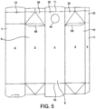
- the carton blank 2 is of a semi-rigid plastics-coated paperboard material, possibly with the interposition of an oxygen barrier layer and comprises a row of panels a to e consisting of a row of side wall parts 4 to 12 consisting of a rear side wall part 4, a lateral side wall part 6, a front side wall part 8, another lateral side wall part 10 and a side-seam part 12; a row of bottom obturating parts 14 to 22; a row of top obturating parts 24 to 32; and a narrow top sealing region 33 comprised of respective top sealing fin parts extending across the top edge of the blank 2.
- the obturating parts 26 and 30 comprise substantially triangular sub-parts 26a, b and c and 30a, b and c.
- the obturating part 24 located above the rear side wall part 4 is separated from the sealing region 33 by a rectilinear line of weakness 34 and the obturating parts 26 and 30 located above the lateral side wall parts 6 and 10 also have a rectilinear line of weakness 34 separating them from the sealing region, but which extends across only approximately half of the width of the obturating parts 26 and 30.
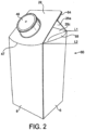
- the front, top, obturating part 28 is formed with a through-hole 44 (or alternatively a loop of weakness) to which is applied a pour spout fitment 46 (see Figure 2 ) but is free from lines of weakness extending inwardly from lateral edge zones of the panel c from an innermost boundary of the top obturating part 28 to an outermost boundary of the adjacent top sealing fin part.
- the obturating part 28 has a boundary with the front side wall part 8 defined by a downwardly bowed line of weakness 47 protruding into the side wall part 8.
- the carton 66 of Figure 2 at all levels of the side wall parts 6,8, 10 and 12, is of square cross-section.
- the top closure sealer jaws of the form-fill-seal machine (not shown), of which there are two; a front sealer jaw and a rear sealer jaw, have, in the sealing position, sealing faces arranged obliquely at an angle of the desired degree of slant and are arranged substantially parallelly to each other.
- the sealing of the sealing fin parts is by hot-air sealing, although other sealing methods are also usable, such as ultrasonic sealing.
- the sealing faces In a non-sealing position, the sealing faces may or may not be in an obliquely arranged position, for example, they may be in a substantially vertical orientation.
- the slanted top-fin 64 is more likely to remain in the desired slanted position, co-planar with the front obturating part 28, as there is no weakness to promote turning of the laminate material. This provides for a relatively mechanically stronger top-fin area since it is more difficult to turn the top-fin 64 relative to the obturating part 28.
- the rear side wall part 4 is longer in the vertical direction than the front side wall part 8, such that the rear obturating part 24 is of a smaller surface area than the front obturating part 28.
- the carton 66 of Figure 2 has an asymmetric type of gable-top closure, where the height of the rear side wall part 4 reaches a greater upper level L1 than the upper level L2 of the front side wall part 8.
- gable transition sub-panels 68 are provided between respective ones of the substantially triangular sub-parts 26c and 30c of the obturating parts 26 and 30 and respective side wall parts 6 and 10.
- the gable transition sub-panels 68 are bounded by a lower line of weakness 68a at their boundary with the side wall parts 6 and 10 and by an upper line of weakness 68b at their boundary with the substantially triangular sub-parts 26c and 30c.
- each transition sub-panel 68 may comprise a plurality of lines of weakness.
- the side wall parts 6 and 10 have respective opposite upper corner zones; the outer upper corner zones (or rearward upper corner zones in the completed carton) furthest from the boundary zone between the side wall part 8 and the obturating part 28 being at a level above that boundary zone, whilst the inner upper corner zones (or forward upper corner zones in the completed carton) closest to and adjacent that boundary zone are at substantially the same level as that boundary zone.
- the carton blank is folded in the gable area during the carton forming process, the amount of turning from between the side wall parts 6 and 10 to the oblique angle of the substantially triangular sub-parts 26c and 30c is reduced by the presence of the gable transition sub-panels 68.
- the gable transition sub-panels 68 also reduce the chances of stretching and/or cracking of the laminate material, especially at the lower, forward corner regions of the gables.
- the gable transition sub-panels 68 also form a convenient advertising area.
- the version of the blank and carton shown in Figures 3 and 4 respectively differs from that of Figures 1 and 2 in that the line of weakness 47 Is also omitted, so that, from a substantially horizontal line of weakness 70 at an outermost boundary of the side wall part 8, separating the front side wall part 8 and its adjacent bottom obturating part 18, to the outermost boundary of the sealing fin part, that is the top edge 72 of the carton, there are no lines of weakness extending inwardly from lateral edge zones of the panel c.
- the only line of weakness that is present is the through-hole 44 (or alternatively a loop of weakness) for the pour spout fitment 46.
- the absence of the line of weakness 47 allows not only even further greater flexibility in the size of the pour spout fitment to be attached than the line of weakness 47 allows, but also allows greater flexibility in the number of parts of the gable-top-forming devices needed in the machine, for example, no special devices or parts for forming the downwardly bowed line of weakness 47 are needed, although devices or parts may be needed to control where bending of the laminate material occurs.
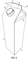
- the version of the blank and cartons shown in Figures 5 and 6 respectively differ from that of the previous versions in that the gable-top carton formed has a vertical top-fin 64 and there is a substantially horizontal line of weakness 71 between the top obturating part 28 and its adjacent sealing fin part, i.e.
- the panel c is free from lines of weakness extending inwardly from lateral edge zones thereof from an outermost boundary of the side wall part 8 (its lowermost boundary) to the outermost boundary of the adjacent obturating part 28 (its uppermost boundary).
- lines of weakness 47 is described immediately above. This version is deemed to be advantageous in that it is envisaged that a production line can be set up using existing form-fill-seal machines without significant modifications being made thereto.
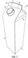
- the carton 66 differs from the carton of Figure 6 in that the transition sub-panel 68 in the gable is of a different form and that the line of weakness 71 is slightly downwardly bowed with respective outer ends of the line of weakness 71 reaching a higher extent than those ends of the substantially horizontal line of weakness 71 in Figure 6 .
- Such a downwardly bowed line of weakness 71 allows for a small extension to the area of the obturating part 28 which results in a larger area for printing-on.
- a similar principle to that of the gable transition sub-panels 68 can be applied to a boundary zone 73 between the front and/or rear obturating parts 24 and 28 and the top-fin 64 of the carton 66.
- the rearwardly slanted top fin 64 there is an acute angle formed between the rear top obturating part 24 and the top-fin 64, and the presence of a top transition sub-panel arrangement 74 bounded by lines of weakness, which diverge outwardly, at the boundary zone 73 can reduce the risk of unwanted stretching and/or cracking of the laminate material when the carton is formed, filled and sealed.
- two such top transition sub-panels of substantially triangular shape are utilised and which extend from respective outer opposite lateral edge zones of the boundary zone 73 to respective apices directed inwardly towards a central region of the boundary zone 73.
- the apices do not touch, but are joined by a short line of weakness 76, since that central region is one of the most significant leakage channels in the carton and thus requires the deepest region of sealing possible.
- top transition sub-panels 74 As with the gable transition sub-panels 68, having a pair of lines of weakness allows for a less abrupt transition In the folding of an angle.
- the top transition sub-panels 74 also reduce the risk of unwanted stretching and/or cracking of the laminate material at a point where there are a plurality of layers of the material at the boundary zone 73 and where an acute angle is to be formed.
- the top obturating parts 26 and 30 also include top transition sub-panels 74 immediately adjacent those of the rear top obturating part 24 when the blank has been side-sealed into a carton sleeve. These top transition sub-panels 74 of the obturating parts 26 and 30 will be folded immediately face-to-face behind those top transition sub-panels 74 on the rear top obturating part 24 when the gable-top closure is formed.
- the carton 66' has a vertical top-fin 64' and the top transition panel arrangement 74' is located at the boundary zone 73' of the front and rear top obturating parts 24' and 28' with the top-fin 64'.
- the gable transition sub-panels 68 may or may not be present with the top transition sub-panel arrangement 74, 74'.
Description
- This invention relates to a packaging carton of semi-rigid packaging material.
US2138718 discloses a container of paper, wood, pulp or the like made from a sheet material container blank folded into shape and closed by bringing two opposite side portions of the container together to form a tapered closure having a sloping side, wherein the intervening side portions of triangular formation are caused to lie flush with the edges of the sloping side of the closure. The container has a front side which comprises a horizontal score line dividing a front side part from a front obturating part and a vertical rear side which does not include any such horizontal score line.WO 2004/076302 A1 discloses a gable top container comprising four side panels, top and bottom closure panels and a pour spout fitment at the top closure panel. - According to a first aspect of the present invention, there is provided a carton blank according to independent claim 1 for forming a gable top carton.
- According to a second aspect of the present invention according to independent claim 3, there is provided a gable top carton.
- Owing to these aspects, greater flexibility can be achieved in the size of the throughflow cross-sectional area of a pour spout fitment to be attached to the carton and/or in the number of machine parts needed for forming the top closure of the carton.
- Where there is no line of weakness between the obturating part and the sealing fin part, which is not according to the claimed invention, a carton can include a top closure having a rearwardly slanted top-fin, with a front top sealing fin part being co-planar with a front top closure obturating part, the slanted top fin being more likely to remain in the desired rearward slanted position because of the absence of any line of weakness of the character mentioned.
- In this way, abrupt edges from folding about a single line of weakness in the gable area of a gable-top carton can be avoided and the risk of undesired stretching and/or cracking of a laminate packaging material, particularly of barrier layers thereof, especially gas barrier layers thereof, can be reduced. This particularly applies to the lower, forward corner regions of the gable areas.
- The transition sub-panels extend obliquely between the respective further substantially triangular sub-parts and the respective second and fourth side wall parts.
- Where a pour spout fitment is provided on the gable-top carton, it may either be inserted outwardly from the inside of an open-topped carton into a hole through the larger, substantially rectangular obturating part; or be provided after sealing of the top of the carton, when the fitment would be applied to the external surface of the larger, substantially rectangular obturating part, round a hole through that part, or around a partial-depth loop of weakness provided in that part, or even with that part intact, depending upon the character of the pour spout fitment. Preferably, the carton further comprises a top closure including a quadrangular obturating sub-panel and disposed outwardly thereof a sealing sub-panel, and lines of weakness extending in a boundary zone between those sub-panels and bounding a transition sub- panel arrangement between said sub-panels, the lines of weakness diverging outwardly.
- In this way, the chance of stretching and/or cracking of the laminate packaging material at the junction between the top closure obturating sub-panel and the top sealing sub-panel can be minimized. The presence of the transition sub-panel arrangement reduces the degree of turning about the lines of weakness than would occur about a single line of weakness at that boundary zone.
- In order that the invention may be clearly and completely disclosed, reference will now be made, by way of example, to the accompanying drawings, in which:-
-
Figure 1 shows a plan view of a carton blank from which a gable-top carton is made, not in accordance with the invention, -
Figure 2 is a perspective view of a formed, filled and sealed gable-top carton made from the blank ofFigure 1 , not in accordance with the invention, -
Figure 3 is a view similar toFigure 1 , but of a blank from which a modified version of the carton which is not in accordance with the claimed invention, is made, -
Figure 4 is a view similar toFigure 2 , but of the modified version of the carton, which is not in accordance with the claimed invention. -
Figure 5 is a view similar toFigure 1 , but of a blank according to the invention. -
Figure 6 is a view similar toFigure 2 , but of a further modified version of the carton, according to the invention. -
Figure 7 is a view similar toFigure 6 , but of yet a further modified version of the carton, according to the invention. -
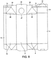
Figure 8 is a plan view of a carton blank similar toFigure 1 , but of another version from which another version of a gable-top carton is made, not in accordance with the invention, -
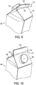
Figure 9 is a perspective view of a top portion of a gable-top carton with a slanted top-fin made from the blank ofFigure 5 , and -
Figure 10 is a view similar toFigure 9 , but with a vertical top-fin, not in accordance with the invention. - Referring to
Figure 1 , the carton blank 2 is of a semi-rigid plastics-coated paperboard material, possibly with the interposition of an oxygen barrier layer and comprises a row of panels a to e consisting of a row ofside wall parts 4 to 12 consisting of a rearside wall part 4, a lateralside wall part 6, a frontside wall part 8, another lateralside wall part 10 and a side-seam part 12; a row ofbottom obturating parts 14 to 22; a row of top obturatingparts 24 to 32; and a narrowtop sealing region 33 comprised of respective top sealing fin parts extending across the top edge of the blank 2. The obturatingparts triangular sub-parts 26a, b and c and 30a, b and c. The obturatingpart 24 located above the rearside wall part 4 is separated from thesealing region 33 by a rectilinear line ofweakness 34 and the obturatingparts side wall parts weakness 34 separating them from the sealing region, but which extends across only approximately half of the width of the obturatingparts part 28 is formed with a through-hole 44 (or alternatively a loop of weakness) to which is applied a pour spout fitment 46 (seeFigure 2 ) but is free from lines of weakness extending inwardly from lateral edge zones of the panel c from an innermost boundary of the top obturatingpart 28 to an outermost boundary of the adjacent top sealing fin part. In order to allow alarger fitment 46 to be mounted in theroof sub-panel 28 than would otherwise be the case, the obturatingpart 28 has a boundary with the frontside wall part 8 defined by a downwardly bowed line ofweakness 47 protruding into theside wall part 8. When the blank 2 ofFigure 1 has been side-seamed, by the heat-sealing of the so-called fifth panel e to the inside of the panel a, thebottom obturating parts 14 to 22 have been closed and sealed, the desired product, for example milk or fruit juice, has been filled into the open-topped carton thus formed, the top obturatingparts 24 to 32 have been closed, and thesealing region 33 sealed to form a rearwardly slantedtop sealing fin 64 that is co- planar with the front obturatingpart 28, thepour spout fitment 46 having been applied before or after top-closure and-sealing of the carton, the formed, filled and sealed, gable-top carton 66 so obtained is as shown inFigure 2 . Thecarton 66 ofFigure 2 , at all levels of theside wall parts - With conventional gable-top cartons with vertical top fins, during the top sealing, the movement of the sealer jaws relative to the laminate packaging material can tend to scratch the material, especially on the top sealing region. However, when the front obturating part and the top-fin are co-planar with each other, as shown in
Figure 2 , the front sealer jaw will not cause such scratching of the packaging material, such that printing of the packaging material (carried out whilst still in the form of the blank 2) can take place over the whole area of the obturatingpart 28 including the sealing region of that part. - With the absence of a line of weakness between the front obturating
part 28 and thesealing region 33, the slanted top-fin 64 is more likely to remain in the desired slanted position, co-planar with the front obturatingpart 28, as there is no weakness to promote turning of the laminate material. This provides for a relatively mechanically stronger top-fin area since it is more difficult to turn the top-fin 64 relative to the obturatingpart 28. It will be noted fromFigure 1 , that the rearside wall part 4 is longer in the vertical direction than the frontside wall part 8, such that the rear obturatingpart 24 is of a smaller surface area than the front obturatingpart 28. Thus, thecarton 66 ofFigure 2 has an asymmetric type of gable-top closure, where the height of the rearside wall part 4 reaches a greater upper level L1 than the upper level L2 of the frontside wall part 8. - In order to be able to fold the blank 2 of
Figure 1 in the gable area,gable transition sub-panels 68 are provided between respective ones of the substantiallytriangular sub-parts parts side wall parts gable transition sub-panels 68 are bounded by a lower line ofweakness 68a at their boundary with theside wall parts weakness 68b at their boundary with the substantiallytriangular sub-parts weakness gable transition sub-panel 68 forming a lanceolate-type shape. Each of thegable transition sub-panels 68, in the version shown, do not extend the whole way across the width of the substantiallytriangular sub-parts Figures 5 ,6 and8 ). In addition, eachtransition sub-panel 68 may comprise a plurality of lines of weakness. Theside wall parts side wall part 8 and the obturatingpart 28 being at a level above that boundary zone, whilst the inner upper corner zones (or forward upper corner zones in the completed carton) closest to and adjacent that boundary zone are at substantially the same level as that boundary zone. When the carton blank is folded in the gable area during the carton forming process, the amount of turning from between theside wall parts triangular sub-parts gable transition sub-panels 68. This way of folding the gable area of the carton not only reduces the presence of abrupt edges in that region that would otherwise be present with a single line of weakness in this area, and which depending on the size of the carton may be a holding region, but thegable transition sub-panels 68 also reduce the chances of stretching and/or cracking of the laminate material, especially at the lower, forward corner regions of the gables. Thegable transition sub-panels 68 also form a convenient advertising area. - The version of the blank and carton shown in
Figures 3 and4 respectively differs from that ofFigures 1 and2 in that the line ofweakness 47 Is also omitted, so that, from a substantially horizontal line ofweakness 70 at an outermost boundary of theside wall part 8, separating the frontside wall part 8 and its adjacentbottom obturating part 18, to the outermost boundary of the sealing fin part, that is thetop edge 72 of the carton, there are no lines of weakness extending inwardly from lateral edge zones of the panel c. The only line of weakness that is present is the through-hole 44 (or alternatively a loop of weakness) for thepour spout fitment 46. The absence of the line ofweakness 47 allows not only even further greater flexibility in the size of the pour spout fitment to be attached than the line ofweakness 47 allows, but also allows greater flexibility in the number of parts of the gable-top-forming devices needed in the machine, for example, no special devices or parts for forming the downwardly bowed line ofweakness 47 are needed, although devices or parts may be needed to control where bending of the laminate material occurs. The version of the blank and cartons shown inFigures 5 and6 respectively, differ from that of the previous versions in that the gable-top carton formed has a vertical top-fin 64 and there is a substantially horizontal line ofweakness 71 between the top obturatingpart 28 and its adjacent sealing fin part, i.e. the panel c is free from lines of weakness extending inwardly from lateral edge zones thereof from an outermost boundary of the side wall part 8 (its lowermost boundary) to the outermost boundary of the adjacent obturating part 28 (its uppermost boundary). The advantage of the absence of the line ofweakness 47 is described immediately above. This version is deemed to be advantageous in that it is envisaged that a production line can be set up using existing form-fill-seal machines without significant modifications being made thereto. - Referring to
Figure 7 , thecarton 66 differs from the carton ofFigure 6 in that thetransition sub-panel 68 in the gable is of a different form and that the line ofweakness 71 is slightly downwardly bowed with respective outer ends of the line ofweakness 71 reaching a higher extent than those ends of the substantially horizontal line ofweakness 71 inFigure 6 . Such a downwardly bowed line ofweakness 71 allows for a small extension to the area of the obturatingpart 28 which results in a larger area for printing-on. Referring toFigures 8 and9 , a similar principle to that of thegable transition sub-panels 68 can be applied to aboundary zone 73 between the front and/or rear obturatingparts fin 64 of thecarton 66. Referring specifically toFigure 9 , with the rearwardly slantedtop fin 64, there is an acute angle formed between the reartop obturating part 24 and the top-fin 64, and the presence of a toptransition sub-panel arrangement 74 bounded by lines of weakness, which diverge outwardly, at theboundary zone 73 can reduce the risk of unwanted stretching and/or cracking of the laminate material when the carton is formed, filled and sealed. In thearrangement 74 shown, two such top transition sub-panels of substantially triangular shape are utilised and which extend from respective outer opposite lateral edge zones of theboundary zone 73 to respective apices directed inwardly towards a central region of theboundary zone 73. At the central region of the boundary zone, the apices do not touch, but are joined by a short line ofweakness 76, since that central region is one of the most significant leakage channels in the carton and thus requires the deepest region of sealing possible. - As with the
gable transition sub-panels 68, having a pair of lines of weakness allows for a less abrupt transition In the folding of an angle. Thetop transition sub-panels 74 also reduce the risk of unwanted stretching and/or cracking of the laminate material at a point where there are a plurality of layers of the material at theboundary zone 73 and where an acute angle is to be formed. It will be noted fromFigure 8 that thetop obturating parts top transition sub-panels 74 immediately adjacent those of the reartop obturating part 24 when the blank has been side-sealed into a carton sleeve. Thesetop transition sub-panels 74 of the obturatingparts top obturating part 24 when the gable-top closure is formed. - Referring to
Figure 10 , it differs fromFigure 9 in that the carton 66' has a vertical top-fin 64' and the top transition panel arrangement 74' is located at the boundary zone 73' of the front and rear top obturating parts 24' and 28' with the top-fin 64'. The gable transition sub-panels 68 may or may not be present with the top transitionsub-panel arrangement 74, 74'.
Claims (4)
- A carton blank made of a semi-rigid plastic-coated paperboard material for forming a carton, and comprising a row of first, second, third and fourth substantially four-edged panels (a-d), each comprising a side wall part (4,6,8,10), a top closure obturating part (24,26,28,30), a bottom obturating part (14,16,18,20) and a top sealing fin part (33),wherein the third panel (c) comprises a first edge forming a boundary with the second panel (b) and a second edge forming a boundary with the fourth panel (d),wherein the top closure obturating part (28) of the third panel (c) includes a through hole (44) or a loop of weakness for a pour spout fitment (46),wherein the third panel (c) comprises a substantially horizontal first line of weakness (71) between the top closure obturating part (28) and the top sealing fin part (33), which first line of weakness (71) forms an uppermost boundary of the top closure obturating part (28), andwherein the third panel (c)comprises a substantially horizontal second line of weakness (70) separating the front side wall part (8) and the bottom obturating part (18), which second line of weakness (70) forms a lowermost boundary of the front side wall part (8),characterised in that the third panel (c)is free from any line of weakness extending inwardly from lateral edge zones of said third panel (c) from the lowermost boundary (70) of the side wall part (8) to the uppermost boundary (71) of the top closure obturating part (28),and in that in this third panel (c) the top closure obturating part (28) has a boundary with the front side wall part (8), extending from said first edge to said second edge, that is free from any line of weakness,wherein the top sealing fin part (33) is configured to form a vertical top-fin (64).
- A carton blank according to claim 1, wherein:- the first and third obturating parts (24,28) are quadrangular,- the first obturating part (24) being of a smaller surface area than that of the third obturating part (28),- the second and fourth obturating parts (26,30) each being comprised of substantially triangular sub-parts (26a-c,30a-c) of which two have boundaries with extents substantially coextensive with the extents of the respective first and third obturating parts, there being transition sub-panels (68) bounded by respective inner lines of weakness (68a) at respective second and fourth side wall parts and respective outer lines of weakness (68b) at respective further substantially triangular sub-parts of the second and fourth obturating parts.
- A carton made of a semi-rigid plastic-coated paperboard material, comprising a loop of first, second, third and fourth substantially four edged panels (a-d), each comprising a side wall part (4,6,8,10), a top closure obturating part (24,26,28,30), a bottom obturating part (14,16,18,20) and a top sealing fin part (64),wherein the third panel (c) comprises a first edge forming a boundary with the second panel (b) and a second edge forming a boundary with the fourth panel (d),wherein the top closure obturating part (28) of the third panel (c) includes a through hole (44) or a loop of weakness for a pour spout fitment (46),wherein the third panel (c) comprises a substantially horizontal first line of weakness (71) between the top closure obturating part (28) and the top sealing fin part (33), which first line of weakness (71) forms an uppermost boundary of the top closure obturating part (28), andwherein the third panel (c) comprises a substantially horizontal second line of weakness (70) separating the front side wall part (8) and the bottom obturating part (18), which second line of weakness (70) forms a lowermost boundary of the front side wall part (8),characterised in that the third panel (c) is free from any line of weakness extending inwardly from lateral edge zones of third panel (c) from the lowermost boundary (70) of the side wall part (8) to the uppermost boundary (71) of the top closure obturating part (28),and in that in this third panel (c) the top closure obturating part (28) has a boundary with the front side wall part (8), extending from said first edge to said second edge, that is free from any line of weakness,wherein the top sealing fin part (33) forms a vertical top-fin (64).
- A carton according to claim 3, wherein:- the first and third obturating parts {24,28) are substantially rectangular and, respectively, rearward and forward top obturating parts,- the first obturating part (24} being of a smaller surface area than the third obturating part (28},- the second and fourth obturating parts (26,30) each being comprised of substantially triangular sub-parts (26a-c,30a-c) of which two have boundaries with extents substantially co-extensive with the extents of the respective first and third obturating parts (24,28),- the first and third obturating parts being in conditions turned inwards about their respective inner boundaries, each said further substantially triangular sub-part (26c,30c) being in a condition turned inwards about its inner boundary, there being transition sub-panels (68) bounded by respective inner lines of weakness (68a) at said second and fourth side wall parts and respective outer lines of weakness (68b) at respective further substantially triangular sub-parts of the second and fourth obturating parts.
Priority Applications (2)
| Application Number | Priority Date | Filing Date | Title |
|---|---|---|---|
| PL14000874T PL2746180T3 (en) | 2008-12-18 | 2009-12-18 | Gable top container |
| EP20161787.5A EP3725696A1 (en) | 2008-12-18 | 2009-12-18 | Gable top container |
Applications Claiming Priority (3)
| Application Number | Priority Date | Filing Date | Title |
|---|---|---|---|
| GBGB0823051.8A GB0823051D0 (en) | 2008-12-18 | 2008-12-18 | Improvements in or relating to packaging |
| PCT/EP2009/067579 WO2010070121A1 (en) | 2008-12-18 | 2009-12-18 | Improvements in or relating to Packaging |
| EP09807669.8A EP2376332B2 (en) | 2008-12-18 | 2009-12-18 | Improvements in or relating to packaging |
Related Parent Applications (2)
| Application Number | Title | Priority Date | Filing Date |
|---|---|---|---|
| EP09807669.8A Division EP2376332B2 (en) | 2008-12-18 | 2009-12-18 | Improvements in or relating to packaging |
| EP09807669.8A Division-Into EP2376332B2 (en) | 2008-12-18 | 2009-12-18 | Improvements in or relating to packaging |
Related Child Applications (2)
| Application Number | Title | Priority Date | Filing Date |
|---|---|---|---|
| EP20161787.5A Division EP3725696A1 (en) | 2008-12-18 | 2009-12-18 | Gable top container |
| EP20161787.5A Division-Into EP3725696A1 (en) | 2008-12-18 | 2009-12-18 | Gable top container |
Publications (4)
| Publication Number | Publication Date |
|---|---|
| EP2746180A2 EP2746180A2 (en) | 2014-06-25 |
| EP2746180A3 EP2746180A3 (en) | 2014-11-05 |
| EP2746180B1 EP2746180B1 (en) | 2020-04-15 |
| EP2746180B2 true EP2746180B2 (en) | 2024-01-31 |
Family
ID=40343775
Family Applications (4)
| Application Number | Title | Priority Date | Filing Date |
|---|---|---|---|
| EP14000873.1A Active EP2743196B1 (en) | 2008-12-18 | 2009-12-18 | Gable top container |
| EP14000874.9A Active EP2746180B2 (en) | 2008-12-18 | 2009-12-18 | Gable top container |
| EP09807669.8A Active EP2376332B2 (en) | 2008-12-18 | 2009-12-18 | Improvements in or relating to packaging |
| EP20161787.5A Pending EP3725696A1 (en) | 2008-12-18 | 2009-12-18 | Gable top container |
Family Applications Before (1)
| Application Number | Title | Priority Date | Filing Date |
|---|---|---|---|
| EP14000873.1A Active EP2743196B1 (en) | 2008-12-18 | 2009-12-18 | Gable top container |
Family Applications After (2)
| Application Number | Title | Priority Date | Filing Date |
|---|---|---|---|
| EP09807669.8A Active EP2376332B2 (en) | 2008-12-18 | 2009-12-18 | Improvements in or relating to packaging |
| EP20161787.5A Pending EP3725696A1 (en) | 2008-12-18 | 2009-12-18 | Gable top container |
Country Status (15)
| Country | Link |
|---|---|
| US (2) | US9452859B2 (en) |
| EP (4) | EP2743196B1 (en) |
| KR (1) | KR101873062B1 (en) |
| AU (1) | AU2016204840B2 (en) |
| CA (1) | CA2747063C (en) |
| CY (1) | CY1116240T1 (en) |
| DK (2) | DK2746180T3 (en) |
| ES (2) | ES2467111T5 (en) |
| FI (1) | FI2746180T4 (en) |
| GB (1) | GB0823051D0 (en) |
| MA (1) | MA32972B1 (en) |
| MX (1) | MX2011006695A (en) |
| PL (2) | PL2746180T3 (en) |
| RU (2) | RU2015107554A (en) |
| WO (1) | WO2010070121A1 (en) |
Families Citing this family (36)
| Publication number | Priority date | Publication date | Assignee | Title |
|---|---|---|---|---|
| JP5573181B2 (en) * | 2010-01-18 | 2014-08-20 | 凸版印刷株式会社 | Liquid paper container with spout |
| US9801969B2 (en) | 2011-03-25 | 2017-10-31 | Szent Bev Co. | Scented attachment for containers |
| US10744223B2 (en) | 2011-03-25 | 2020-08-18 | Szent Co. | Scented material compositions and articles for use with food and beverage |
| GB201117986D0 (en) * | 2011-10-18 | 2011-11-30 | Elopak Systems | Improvements in or relating to packaging |
| EP2641838B2 (en) † | 2012-03-23 | 2017-09-27 | Tetra Laval Holdings & Finance S.A. | Packaging container and blank for a packaging container |
| CA170845S (en) * | 2013-11-15 | 2020-02-03 | Elopak Systems | Packaging carton |
| USD786070S1 (en) * | 2015-04-15 | 2017-05-09 | Tetra Laval Holdings & Finance S.A. | Packaging and blank therefor |
| USD786065S1 (en) * | 2015-04-15 | 2017-05-09 | Tetra Laval Holdings & Finance S.A. | Packaging and blank therefor |
| USD786066S1 (en) * | 2015-04-15 | 2017-05-09 | Tetra Laval Holdings & Finance S.A. | Packaging and blank therefor |
| USD786067S1 (en) * | 2015-04-15 | 2017-05-09 | Tetra Laval Holdings & Finance S.A. | Packaging and blank therefor |
| USD786069S1 (en) * | 2015-04-15 | 2017-05-09 | Tetra Laval Holdings & Finance S.A. | Packaging and blank therefor |
| USD786068S1 (en) * | 2015-04-15 | 2017-05-09 | Tetra Laval Holdings & Finance S.A. | Packaging and blank therefor |
| USD786064S1 (en) * | 2015-04-15 | 2017-05-09 | Tetra Laval Holdings & Finance S.A. | Packaging and blank therefor |
| USD799957S1 (en) * | 2015-05-14 | 2017-10-17 | Mirco Onesti | Packaging |
| RU171097U1 (en) * | 2015-12-22 | 2017-05-19 | Рустем Рафкатович Каримов | FOLDING TRAY |
| DE102016003829A1 (en) * | 2016-04-04 | 2017-10-05 | Sig Technology Ag | Packing jacket, package and method of making a package |
| USD844430S1 (en) * | 2016-04-04 | 2019-04-02 | Sig Technology Ag | Beverage carton |
| USD829547S1 (en) | 2016-04-25 | 2018-10-02 | Tetra Laval Holdings & Finance S.A. | Package |
| JP6819074B2 (en) * | 2016-05-11 | 2021-01-27 | 凸版印刷株式会社 | Goebel top type packaging container |
| JP6759694B2 (en) * | 2016-05-11 | 2020-09-23 | 凸版印刷株式会社 | Goebel top type packaging container |
| USD845124S1 (en) * | 2016-10-21 | 2019-04-09 | Elopak A/S | Carton |
| JP6618085B2 (en) * | 2017-03-31 | 2019-12-11 | 日本製紙株式会社 | Paper container |
| USD859980S1 (en) * | 2017-06-02 | 2019-09-17 | Tetra Laval Holdings & Finance S.A. | Package |
| DE102017215078A1 (en) * | 2017-08-29 | 2019-02-28 | Sig Technology Ag | Sheet-like composite, in particular for producing dimensionally stable food containers, having a roof surface formed by a multiplicity of partially convexly curved creasing lines |
| USD881694S1 (en) * | 2017-08-31 | 2020-04-21 | Tetra Laval Holdings & Finance S.A. | Package with base closure, top closure and side panel edge |
| USD881693S1 (en) * | 2017-08-31 | 2020-04-21 | Tetra Laval Holdings & Finance S.A. | Package with base closure, top closure, side panel edge and kite shaped edge |
| USD881696S1 (en) * | 2017-08-31 | 2020-04-21 | Tetra Laval Holdings & Finance S.A. | Package with base closure, top closure, side panel edge and rhomboid shaped edge |
| USD881697S1 (en) * | 2017-08-31 | 2020-04-21 | Tetra Laval Holdings & Finance S.A. | Package with base closure, top closure, side panel edge and side panel features |
| USD881695S1 (en) * | 2017-08-31 | 2020-04-21 | Tetra Laval Holdings & Finance S.A. | Package with base closure, top closure, side panel edge and twisted edge |
| USD889958S1 (en) * | 2017-08-31 | 2020-07-14 | Tetra Laval Holdings & Finance S.A. | Package with base closure, top closure, side panel edge and tear shaped edge |
| JP6878231B2 (en) * | 2017-09-25 | 2021-05-26 | 日本製紙株式会社 | Liquid paper container |
| DE102017131262A1 (en) * | 2017-12-22 | 2019-07-11 | Sig Technology Ag | Container made of packing coats and an outer packaging |
| USD950384S1 (en) | 2018-05-16 | 2022-05-03 | Szent Co. | Bottle |
| US11097877B2 (en) | 2018-05-31 | 2021-08-24 | Szent Co. | Scent delivery and preservation systems and methods for beverage containers |
| USD935880S1 (en) * | 2019-04-16 | 2021-11-16 | Elopak As | Packaging container |
| US11312528B2 (en) | 2019-10-07 | 2022-04-26 | Szent Co. | Scented attachments for beverage cartons |
Citations (1)
| Publication number | Priority date | Publication date | Assignee | Title |
|---|---|---|---|---|
| WO2004076302A1 (en) † | 2003-02-25 | 2004-09-10 | Elopak Systems Ag | Carton with pour spout |
Family Cites Families (28)
| Publication number | Priority date | Publication date | Assignee | Title |
|---|---|---|---|---|
| NL54964C (en) * | ||||
| BE401923A (en) * | 1933-04-13 | 1934-04-30 | Hartmann, Carl Wilhelm | CONTAINER OR BOX IN PAPER, CARDBOARD OR SIMILAR |
| US2138718A (en) * | 1935-02-28 | 1938-11-29 | Wheeler John William | Bottle or container of paper, wood pulp, or the like |
| DE680633C (en) * | 1938-04-03 | 1939-09-02 | Jagenberg Werke Ag | Cutting and method of making a paper vessel |
| US2321139A (en) * | 1940-08-19 | 1943-06-08 | Edward H Gruger | Collapsible paper container |
| GB732682A (en) * | 1952-06-10 | 1955-06-29 | George Stewart Vivian | Improvements in or relating to cartons |
| US3185375A (en) * | 1962-09-28 | 1965-05-25 | Ex Cell O Corp | Container with a gable top closure |
| US3349988A (en) * | 1966-04-20 | 1967-10-31 | Phillips Petroleum Co | Gable top container with notched ridge |
| US3471076A (en) * | 1967-10-17 | 1969-10-07 | Ex Cell O Corp | Container closure construction |
| CA1036982A (en) * | 1974-07-15 | 1978-08-22 | Nimco Corporation | Liquid-tight flat top container |
| DE4000136C1 (en) | 1990-01-04 | 1991-08-01 | Unilever N.V., Rotterdam, Nl | |
| DE4020222C2 (en) * | 1990-06-26 | 1994-02-24 | 4 P Nicolaus Kempten Gmbh | Cardboard packaging or the like |
| SE9100921L (en) | 1991-03-27 | 1992-09-28 | Tetra Alfa Holdings | OPENING DEVICE FOR A PACKAGING CONTAINER AND WAY TO MANUFACTURE THEM |
| JP3483593B2 (en) | 1993-07-15 | 2004-01-06 | 日本テトラパック株式会社 | Packaging container sealing device |
| US5848749A (en) * | 1994-05-06 | 1998-12-15 | Tetra Laval Holdings & Finance, Sa | Gable top carton and carton blank with curved side creases and coincident corner creases |
| WO1996037412A1 (en) * | 1995-05-23 | 1996-11-28 | Easycarton Limited | Opening means for gable top container |
| US5785240A (en) * | 1996-08-19 | 1998-07-28 | Elopak Systems Ag | Top closure arrangement for a rectangular container |
| JPH11236027A (en) * | 1998-02-20 | 1999-08-31 | Dainippon Printing Co Ltd | Deformed gable top carton |
| US6139480A (en) | 1999-01-28 | 2000-10-31 | Tetra Laval Holdings & Finance, Sa | Cutting device for effecting a partial cut in a packaging material, and a blank produced therefrom |
| JP2000289736A (en) | 1999-04-08 | 2000-10-17 | Toppan Printing Co Ltd | Blank for paper container |
| US6182887B1 (en) * | 1999-04-16 | 2001-02-06 | Tetra Laval Holdings & Finance, Sa | Package with extended top panel and a blank therefor |
| EP1493678B1 (en) * | 2000-07-11 | 2007-09-19 | Tetra Laval Holdings & Finance SA | Sealed package for pourable food products, and relative production method |
| AU7669601A (en) | 2000-07-31 | 2002-02-13 | Tetra Laval Holdings & Finance | Method of manufacturing paper packaging container and paper packaging container |
| JP2002234524A (en) * | 2001-02-07 | 2002-08-20 | Toppan Printing Co Ltd | Gable-top type paper container |
| JP4442796B2 (en) * | 2003-01-24 | 2010-03-31 | 日本テトラパック株式会社 | Packaging container and spigot attached to packaging container |
| EP1584563A1 (en) * | 2004-04-09 | 2005-10-12 | Tetra Laval Holdings & Finance S.A. | Gable-top package for pourable food products and method for dimensioning thereof |
| US20070036471A1 (en) | 2005-08-11 | 2007-02-15 | George Anasis | Freestanding upright mounted storage bag with grip for inverted application |
| USD623537S1 (en) * | 2006-12-11 | 2010-09-14 | Bosch Pouch Systems Ag | Triangular pouch with large spout |
-
2008
- 2008-12-18 GB GBGB0823051.8A patent/GB0823051D0/en not_active Ceased
-
2009
- 2009-12-18 MA MA34022A patent/MA32972B1/en unknown
- 2009-12-18 EP EP14000873.1A patent/EP2743196B1/en active Active
- 2009-12-18 FI FIEP14000874.9T patent/FI2746180T4/en active
- 2009-12-18 EP EP14000874.9A patent/EP2746180B2/en active Active
- 2009-12-18 ES ES09807669T patent/ES2467111T5/en active Active
- 2009-12-18 RU RU2015107554/12A patent/RU2015107554A/en not_active Application Discontinuation
- 2009-12-18 WO PCT/EP2009/067579 patent/WO2010070121A1/en active Application Filing
- 2009-12-18 DK DK14000874.9T patent/DK2746180T3/en active
- 2009-12-18 CA CA2747063A patent/CA2747063C/en active Active
- 2009-12-18 EP EP09807669.8A patent/EP2376332B2/en active Active
- 2009-12-18 PL PL14000874T patent/PL2746180T3/en unknown
- 2009-12-18 ES ES14000874T patent/ES2806251T3/en active Active
- 2009-12-18 KR KR1020117016333A patent/KR101873062B1/en active IP Right Grant
- 2009-12-18 MX MX2011006695A patent/MX2011006695A/en active IP Right Grant
- 2009-12-18 DK DK09807669.8T patent/DK2376332T4/en active
- 2009-12-18 RU RU2011129398/12A patent/RU2547605C2/en active
- 2009-12-18 PL PL09807669T patent/PL2376332T5/en unknown
- 2009-12-18 EP EP20161787.5A patent/EP3725696A1/en active Pending
- 2009-12-18 US US12/998,919 patent/US9452859B2/en active Active
-
2014
- 2014-06-11 CY CY20141100421T patent/CY1116240T1/en unknown
-
2016
- 2016-07-11 AU AU2016204840A patent/AU2016204840B2/en active Active
- 2016-08-26 US US15/248,904 patent/US10472125B2/en active Active
Patent Citations (1)
| Publication number | Priority date | Publication date | Assignee | Title |
|---|---|---|---|---|
| WO2004076302A1 (en) † | 2003-02-25 | 2004-09-10 | Elopak Systems Ag | Carton with pour spout |
Also Published As
Similar Documents
| Publication | Publication Date | Title |
|---|---|---|
| EP2746180B2 (en) | Gable top container | |
| AU2016213850B2 (en) | Improvements in or relating to packaging | |
| US9227750B2 (en) | Carton with pour spout | |
| CN107264910B (en) | Composite package, package laminate and packaging sleeve blank for composite package | |
| WO2009101029A1 (en) | Container made of material, blank and methods | |
| WO2009030910A2 (en) | Improvements in or relating to packaging | |
| AU2009329477B8 (en) | Improvements in or relating to Packaging | |
| US10828857B2 (en) | Anvil device | |
| AU2011202535A1 (en) | Carton with pour spout |
Legal Events
| Date | Code | Title | Description |
|---|---|---|---|
| PUAI | Public reference made under article 153(3) epc to a published international application that has entered the european phase |
Free format text: ORIGINAL CODE: 0009012 |
|
| 17P | Request for examination filed |
Effective date: 20140312 |
|
| AC | Divisional application: reference to earlier application |
Ref document number: 2376332 Country of ref document: EP Kind code of ref document: P |
|
| AK | Designated contracting states |
Kind code of ref document: A2 Designated state(s): AT BE BG CH CY CZ DE DK EE ES FI FR GB GR HR HU IE IS IT LI LT LU LV MC MK MT NL NO PL PT RO SE SI SK SM TR |
|
| PUAL | Search report despatched |
Free format text: ORIGINAL CODE: 0009013 |
|
| AK | Designated contracting states |
Kind code of ref document: A3 Designated state(s): AT BE BG CH CY CZ DE DK EE ES FI FR GB GR HR HU IE IS IT LI LT LU LV MC MK MT NL NO PL PT RO SE SI SK SM TR |
|
| RIC1 | Information provided on ipc code assigned before grant |
Ipc: B65D 5/74 20060101ALI20140930BHEP Ipc: B65D 5/06 20060101AFI20140930BHEP |
|
| RIC1 | Information provided on ipc code assigned before grant |
Ipc: B65D 5/06 20060101AFI20141008BHEP Ipc: B65D 5/74 20060101ALI20141008BHEP |
|
| R17P | Request for examination filed (corrected) |
Effective date: 20150501 |
|
| RBV | Designated contracting states (corrected) |
Designated state(s): AT BE BG CH CY CZ DE DK EE ES FI FR GB GR HR HU IE IS IT LI LT LU LV MC MK MT NL NO PL PT RO SE SI SK SM TR |
|
| 17Q | First examination report despatched |
Effective date: 20160406 |
|
| STAA | Information on the status of an ep patent application or granted ep patent |
Free format text: STATUS: EXAMINATION IS IN PROGRESS |
|
| TPAC | Observations filed by third parties |
Free format text: ORIGINAL CODE: EPIDOSNTIPA |
|
| GRAP | Despatch of communication of intention to grant a patent |
Free format text: ORIGINAL CODE: EPIDOSNIGR1 |
|
| STAA | Information on the status of an ep patent application or granted ep patent |
Free format text: STATUS: GRANT OF PATENT IS INTENDED |
|
| INTG | Intention to grant announced |
Effective date: 20191030 |
|
| GRAS | Grant fee paid |
Free format text: ORIGINAL CODE: EPIDOSNIGR3 |
|
| GRAA | (expected) grant |
Free format text: ORIGINAL CODE: 0009210 |
|
| STAA | Information on the status of an ep patent application or granted ep patent |
Free format text: STATUS: THE PATENT HAS BEEN GRANTED |
|
| AC | Divisional application: reference to earlier application |
Ref document number: 2376332 Country of ref document: EP Kind code of ref document: P |
|
| AK | Designated contracting states |
Kind code of ref document: B1 Designated state(s): AT BE BG CH CY CZ DE DK EE ES FI FR GB GR HR HU IE IS IT LI LT LU LV MC MK MT NL NO PL PT RO SE SI SK SM TR |
|
| REG | Reference to a national code |
Ref country code: CH Ref legal event code: EP |
|
| REG | Reference to a national code |
Ref country code: DE Ref legal event code: R096 Ref document number: 602009061766 Country of ref document: DE |
|
| REG | Reference to a national code |
Ref country code: IE Ref legal event code: FG4D |
|
| REG | Reference to a national code |
Ref country code: AT Ref legal event code: REF Ref document number: 1257013 Country of ref document: AT Kind code of ref document: T Effective date: 20200515 |
|
| REG | Reference to a national code |
Ref country code: FI Ref legal event code: FGE |
|
| REG | Reference to a national code |
Ref country code: DK Ref legal event code: T3 Effective date: 20200721 |
|
| REG | Reference to a national code |
Ref country code: NL Ref legal event code: FP |
|
| REG | Reference to a national code |
Ref country code: SE Ref legal event code: TRGR |
|
| REG | Reference to a national code |
Ref country code: NL Ref legal event code: PD Owner name: ELOPAK AS; NO Free format text: DETAILS ASSIGNMENT: CHANGE OF OWNER(S), ASSIGNMENT; FORMER OWNER NAME: ELOPAK SYSTEMS AG Effective date: 20200715 |
|
| RAP2 | Party data changed (patent owner data changed or rights of a patent transferred) |
Owner name: ELOPAK AS |
|
| REG | Reference to a national code |
Ref country code: NO Ref legal event code: T2 Effective date: 20200415 |
|
| REG | Reference to a national code |
Ref country code: GR Ref legal event code: EP Ref document number: 20200401967 Country of ref document: GR Effective date: 20200916 |
|
| REG | Reference to a national code |
Ref country code: LT Ref legal event code: MG4D |
|
| PG25 | Lapsed in a contracting state [announced via postgrant information from national office to epo] |
Ref country code: PT Free format text: LAPSE BECAUSE OF FAILURE TO SUBMIT A TRANSLATION OF THE DESCRIPTION OR TO PAY THE FEE WITHIN THE PRESCRIBED TIME-LIMIT Effective date: 20200817 Ref country code: LT Free format text: LAPSE BECAUSE OF FAILURE TO SUBMIT A TRANSLATION OF THE DESCRIPTION OR TO PAY THE FEE WITHIN THE PRESCRIBED TIME-LIMIT Effective date: 20200415 Ref country code: IS Free format text: LAPSE BECAUSE OF FAILURE TO SUBMIT A TRANSLATION OF THE DESCRIPTION OR TO PAY THE FEE WITHIN THE PRESCRIBED TIME-LIMIT Effective date: 20200815 |
|
| REG | Reference to a national code |
Ref country code: AT Ref legal event code: PC Ref document number: 1257013 Country of ref document: AT Kind code of ref document: T Owner name: ELOPAK AS, NO Effective date: 20200921 |
|
| PG25 | Lapsed in a contracting state [announced via postgrant information from national office to epo] |
Ref country code: LV Free format text: LAPSE BECAUSE OF FAILURE TO SUBMIT A TRANSLATION OF THE DESCRIPTION OR TO PAY THE FEE WITHIN THE PRESCRIBED TIME-LIMIT Effective date: 20200415 Ref country code: HR Free format text: LAPSE BECAUSE OF FAILURE TO SUBMIT A TRANSLATION OF THE DESCRIPTION OR TO PAY THE FEE WITHIN THE PRESCRIBED TIME-LIMIT Effective date: 20200415 Ref country code: BG Free format text: LAPSE BECAUSE OF FAILURE TO SUBMIT A TRANSLATION OF THE DESCRIPTION OR TO PAY THE FEE WITHIN THE PRESCRIBED TIME-LIMIT Effective date: 20200715 |
|
| REG | Reference to a national code |
Ref country code: DE Ref legal event code: R026 Ref document number: 602009061766 Country of ref document: DE |
|
| PLBI | Opposition filed |
Free format text: ORIGINAL CODE: 0009260 |
|
| REG | Reference to a national code |
Ref country code: FI Ref legal event code: MDE Opponent name: TETRA LAVAL HOLDINGS & FINANCE SA |
|
| 26 | Opposition filed |
Opponent name: TETRA LAVAL HOLDINGS & FINANCE SA Effective date: 20201222 |
|
| PLAX | Notice of opposition and request to file observation + time limit sent |
Free format text: ORIGINAL CODE: EPIDOSNOBS2 |
|
| PG25 | Lapsed in a contracting state [announced via postgrant information from national office to epo] |
Ref country code: EE Free format text: LAPSE BECAUSE OF FAILURE TO SUBMIT A TRANSLATION OF THE DESCRIPTION OR TO PAY THE FEE WITHIN THE PRESCRIBED TIME-LIMIT Effective date: 20200415 Ref country code: SM Free format text: LAPSE BECAUSE OF FAILURE TO SUBMIT A TRANSLATION OF THE DESCRIPTION OR TO PAY THE FEE WITHIN THE PRESCRIBED TIME-LIMIT Effective date: 20200415 Ref country code: CZ Free format text: LAPSE BECAUSE OF FAILURE TO SUBMIT A TRANSLATION OF THE DESCRIPTION OR TO PAY THE FEE WITHIN THE PRESCRIBED TIME-LIMIT Effective date: 20200415 Ref country code: RO Free format text: LAPSE BECAUSE OF FAILURE TO SUBMIT A TRANSLATION OF THE DESCRIPTION OR TO PAY THE FEE WITHIN THE PRESCRIBED TIME-LIMIT Effective date: 20200415 |
|
| REG | Reference to a national code |
Ref country code: ES Ref legal event code: FG2A Ref document number: 2806251 Country of ref document: ES Kind code of ref document: T3 Effective date: 20210217 |
|
| PG25 | Lapsed in a contracting state [announced via postgrant information from national office to epo] |
Ref country code: SK Free format text: LAPSE BECAUSE OF FAILURE TO SUBMIT A TRANSLATION OF THE DESCRIPTION OR TO PAY THE FEE WITHIN THE PRESCRIBED TIME-LIMIT Effective date: 20200415 |
|
| PG25 | Lapsed in a contracting state [announced via postgrant information from national office to epo] |
Ref country code: SI Free format text: LAPSE BECAUSE OF FAILURE TO SUBMIT A TRANSLATION OF THE DESCRIPTION OR TO PAY THE FEE WITHIN THE PRESCRIBED TIME-LIMIT Effective date: 20200415 |
|
| PLBB | Reply of patent proprietor to notice(s) of opposition received |
Free format text: ORIGINAL CODE: EPIDOSNOBS3 |
|
| REG | Reference to a national code |
Ref country code: CH Ref legal event code: PL |
|
| PG25 | Lapsed in a contracting state [announced via postgrant information from national office to epo] |
Ref country code: MC Free format text: LAPSE BECAUSE OF FAILURE TO SUBMIT A TRANSLATION OF THE DESCRIPTION OR TO PAY THE FEE WITHIN THE PRESCRIBED TIME-LIMIT Effective date: 20200415 |
|
| REG | Reference to a national code |
Ref country code: BE Ref legal event code: MM Effective date: 20201231 |
|
| PG25 | Lapsed in a contracting state [announced via postgrant information from national office to epo] |
Ref country code: IE Free format text: LAPSE BECAUSE OF NON-PAYMENT OF DUE FEES Effective date: 20201218 Ref country code: LU Free format text: LAPSE BECAUSE OF NON-PAYMENT OF DUE FEES Effective date: 20201218 |
|
| PG25 | Lapsed in a contracting state [announced via postgrant information from national office to epo] |
Ref country code: LI Free format text: LAPSE BECAUSE OF NON-PAYMENT OF DUE FEES Effective date: 20201231 Ref country code: CH Free format text: LAPSE BECAUSE OF NON-PAYMENT OF DUE FEES Effective date: 20201231 |
|
| PG25 | Lapsed in a contracting state [announced via postgrant information from national office to epo] |
Ref country code: MT Free format text: LAPSE BECAUSE OF FAILURE TO SUBMIT A TRANSLATION OF THE DESCRIPTION OR TO PAY THE FEE WITHIN THE PRESCRIBED TIME-LIMIT Effective date: 20200415 Ref country code: CY Free format text: LAPSE BECAUSE OF FAILURE TO SUBMIT A TRANSLATION OF THE DESCRIPTION OR TO PAY THE FEE WITHIN THE PRESCRIBED TIME-LIMIT Effective date: 20200415 |
|
| PG25 | Lapsed in a contracting state [announced via postgrant information from national office to epo] |
Ref country code: MK Free format text: LAPSE BECAUSE OF FAILURE TO SUBMIT A TRANSLATION OF THE DESCRIPTION OR TO PAY THE FEE WITHIN THE PRESCRIBED TIME-LIMIT Effective date: 20200415 |
|
| PG25 | Lapsed in a contracting state [announced via postgrant information from national office to epo] |
Ref country code: BE Free format text: LAPSE BECAUSE OF NON-PAYMENT OF DUE FEES Effective date: 20201231 |
|
| REG | Reference to a national code |
Ref country code: AT Ref legal event code: UEP Ref document number: 1257013 Country of ref document: AT Kind code of ref document: T Effective date: 20200415 |
|
| PGFP | Annual fee paid to national office [announced via postgrant information from national office to epo] |
Ref country code: PL Payment date: 20221121 Year of fee payment: 14 |
|
| PGFP | Annual fee paid to national office [announced via postgrant information from national office to epo] |
Ref country code: TR Payment date: 20221215 Year of fee payment: 14 Ref country code: ES Payment date: 20230227 Year of fee payment: 14 |
|
| P01 | Opt-out of the competence of the unified patent court (upc) registered |
Effective date: 20230523 |
|
| PUAH | Patent maintained in amended form |
Free format text: ORIGINAL CODE: 0009272 |
|
| STAA | Information on the status of an ep patent application or granted ep patent |
Free format text: STATUS: PATENT MAINTAINED AS AMENDED |
|
| PGFP | Annual fee paid to national office [announced via postgrant information from national office to epo] |
Ref country code: GB Payment date: 20231220 Year of fee payment: 15 Ref country code: GR Payment date: 20231221 Year of fee payment: 15 |
|
| 27A | Patent maintained in amended form |
Effective date: 20240131 |
|
| AK | Designated contracting states |
Kind code of ref document: B2 Designated state(s): AT BE BG CH CY CZ DE DK EE ES FI FR GB GR HR HU IE IS IT LI LT LU LV MC MK MT NL NO PL PT RO SE SI SK SM TR |
|
| PGFP | Annual fee paid to national office [announced via postgrant information from national office to epo] |
Ref country code: SE Payment date: 20231220 Year of fee payment: 15 Ref country code: NO Payment date: 20231222 Year of fee payment: 15 Ref country code: NL Payment date: 20231220 Year of fee payment: 15 Ref country code: IT Payment date: 20231221 Year of fee payment: 15 Ref country code: FR Payment date: 20231221 Year of fee payment: 15 Ref country code: FI Payment date: 20231220 Year of fee payment: 15 Ref country code: DK Payment date: 20231227 Year of fee payment: 15 Ref country code: DE Payment date: 20231214 Year of fee payment: 15 Ref country code: AT Payment date: 20231221 Year of fee payment: 15 |
|
| REG | Reference to a national code |
Ref country code: DE Ref legal event code: R102 Ref document number: 602009061766 Country of ref document: DE |
|
| PGFP | Annual fee paid to national office [announced via postgrant information from national office to epo] |
Ref country code: PL Payment date: 20231124 Year of fee payment: 15 |
|
| PGFP | Annual fee paid to national office [announced via postgrant information from national office to epo] |
Ref country code: ES Payment date: 20240126 Year of fee payment: 15 |