EP2746106A1 - Vehicle functional component - Google Patents
Vehicle functional component Download PDFInfo
- Publication number
- EP2746106A1 EP2746106A1 EP12821924.3A EP12821924A EP2746106A1 EP 2746106 A1 EP2746106 A1 EP 2746106A1 EP 12821924 A EP12821924 A EP 12821924A EP 2746106 A1 EP2746106 A1 EP 2746106A1
- Authority
- EP
- European Patent Office
- Prior art keywords
- light
- emitting
- emitting device
- vehicle
- molded
- Prior art date
- Legal status (The legal status is an assumption and is not a legal conclusion. Google has not performed a legal analysis and makes no representation as to the accuracy of the status listed.)
- Granted
Links
- 239000011347 resin Substances 0.000 claims abstract description 56
- 229920005989 resin Polymers 0.000 claims abstract description 56
- 238000000465 moulding Methods 0.000 claims abstract description 31
- 239000007787 solid Substances 0.000 claims abstract description 11
- 230000000873 masking effect Effects 0.000 claims description 16
- 230000000694 effects Effects 0.000 claims description 11
- 238000009792 diffusion process Methods 0.000 claims description 9
- 235000021189 garnishes Nutrition 0.000 claims description 8
- 230000003760 hair shine Effects 0.000 claims description 3
- 230000003796 beauty Effects 0.000 abstract description 4
- 230000001771 impaired effect Effects 0.000 abstract description 2
- 239000010408 film Substances 0.000 description 34
- 230000006870 function Effects 0.000 description 12
- 238000009826 distribution Methods 0.000 description 8
- 238000011282 treatment Methods 0.000 description 6
- 239000008186 active pharmaceutical agent Substances 0.000 description 5
- 230000015572 biosynthetic process Effects 0.000 description 5
- 230000000994 depressogenic effect Effects 0.000 description 5
- 239000000945 filler Substances 0.000 description 5
- 238000000576 coating method Methods 0.000 description 4
- 238000000034 method Methods 0.000 description 4
- 239000011248 coating agent Substances 0.000 description 3
- 238000005520 cutting process Methods 0.000 description 3
- 239000000463 material Substances 0.000 description 3
- 239000011247 coating layer Substances 0.000 description 2
- 239000000470 constituent Substances 0.000 description 2
- 230000001678 irradiating effect Effects 0.000 description 2
- 230000036961 partial effect Effects 0.000 description 2
- 238000004080 punching Methods 0.000 description 2
- 239000003795 chemical substances by application Substances 0.000 description 1
- 238000004040 coloring Methods 0.000 description 1
- 238000005323 electroforming Methods 0.000 description 1
- 238000003780 insertion Methods 0.000 description 1
- 230000037431 insertion Effects 0.000 description 1
- 230000010354 integration Effects 0.000 description 1
- 239000010410 layer Substances 0.000 description 1
- 239000003550 marker Substances 0.000 description 1
- 239000000203 mixture Substances 0.000 description 1
- 239000003973 paint Substances 0.000 description 1
- 239000002245 particle Substances 0.000 description 1
- 238000007747 plating Methods 0.000 description 1
- 230000010287 polarization Effects 0.000 description 1
- 230000009993 protective function Effects 0.000 description 1
- 230000000717 retained effect Effects 0.000 description 1
- 230000002441 reversible effect Effects 0.000 description 1
- 239000002356 single layer Substances 0.000 description 1
- 238000004381 surface treatment Methods 0.000 description 1
- 239000010409 thin film Substances 0.000 description 1
- 238000002834 transmittance Methods 0.000 description 1
Images


Classifications
-
- B—PERFORMING OPERATIONS; TRANSPORTING
- B60—VEHICLES IN GENERAL
- B60Q—ARRANGEMENT OF SIGNALLING OR LIGHTING DEVICES, THE MOUNTING OR SUPPORTING THEREOF OR CIRCUITS THEREFOR, FOR VEHICLES IN GENERAL
- B60Q1/00—Arrangement of optical signalling or lighting devices, the mounting or supporting thereof or circuits therefor
- B60Q1/26—Arrangement of optical signalling or lighting devices, the mounting or supporting thereof or circuits therefor the devices being primarily intended to indicate the vehicle, or parts thereof, or to give signals, to other traffic
- B60Q1/32—Arrangement of optical signalling or lighting devices, the mounting or supporting thereof or circuits therefor the devices being primarily intended to indicate the vehicle, or parts thereof, or to give signals, to other traffic for indicating vehicle sides, e.g. clearance lights
-
- B—PERFORMING OPERATIONS; TRANSPORTING
- B60—VEHICLES IN GENERAL
- B60Q—ARRANGEMENT OF SIGNALLING OR LIGHTING DEVICES, THE MOUNTING OR SUPPORTING THEREOF OR CIRCUITS THEREFOR, FOR VEHICLES IN GENERAL
- B60Q1/00—Arrangement of optical signalling or lighting devices, the mounting or supporting thereof or circuits therefor
- B60Q1/26—Arrangement of optical signalling or lighting devices, the mounting or supporting thereof or circuits therefor the devices being primarily intended to indicate the vehicle, or parts thereof, or to give signals, to other traffic
- B60Q1/2661—Arrangement of optical signalling or lighting devices, the mounting or supporting thereof or circuits therefor the devices being primarily intended to indicate the vehicle, or parts thereof, or to give signals, to other traffic mounted on parts having other functions
-
- B—PERFORMING OPERATIONS; TRANSPORTING
- B60—VEHICLES IN GENERAL
- B60J—WINDOWS, WINDSCREENS, NON-FIXED ROOFS, DOORS, OR SIMILAR DEVICES FOR VEHICLES; REMOVABLE EXTERNAL PROTECTIVE COVERINGS SPECIALLY ADAPTED FOR VEHICLES
- B60J5/00—Doors
- B60J5/04—Doors arranged at the vehicle sides
-
- B—PERFORMING OPERATIONS; TRANSPORTING
- B60—VEHICLES IN GENERAL
- B60Q—ARRANGEMENT OF SIGNALLING OR LIGHTING DEVICES, THE MOUNTING OR SUPPORTING THEREOF OR CIRCUITS THEREFOR, FOR VEHICLES IN GENERAL
- B60Q1/00—Arrangement of optical signalling or lighting devices, the mounting or supporting thereof or circuits therefor
- B60Q1/26—Arrangement of optical signalling or lighting devices, the mounting or supporting thereof or circuits therefor the devices being primarily intended to indicate the vehicle, or parts thereof, or to give signals, to other traffic
- B60Q1/2661—Arrangement of optical signalling or lighting devices, the mounting or supporting thereof or circuits therefor the devices being primarily intended to indicate the vehicle, or parts thereof, or to give signals, to other traffic mounted on parts having other functions
- B60Q1/2665—Arrangement of optical signalling or lighting devices, the mounting or supporting thereof or circuits therefor the devices being primarily intended to indicate the vehicle, or parts thereof, or to give signals, to other traffic mounted on parts having other functions on rear-view mirrors
-
- B—PERFORMING OPERATIONS; TRANSPORTING
- B60—VEHICLES IN GENERAL
- B60Q—ARRANGEMENT OF SIGNALLING OR LIGHTING DEVICES, THE MOUNTING OR SUPPORTING THEREOF OR CIRCUITS THEREFOR, FOR VEHICLES IN GENERAL
- B60Q1/00—Arrangement of optical signalling or lighting devices, the mounting or supporting thereof or circuits therefor
- B60Q1/26—Arrangement of optical signalling or lighting devices, the mounting or supporting thereof or circuits therefor the devices being primarily intended to indicate the vehicle, or parts thereof, or to give signals, to other traffic
- B60Q1/2661—Arrangement of optical signalling or lighting devices, the mounting or supporting thereof or circuits therefor the devices being primarily intended to indicate the vehicle, or parts thereof, or to give signals, to other traffic mounted on parts having other functions
- B60Q1/2669—Arrangement of optical signalling or lighting devices, the mounting or supporting thereof or circuits therefor the devices being primarily intended to indicate the vehicle, or parts thereof, or to give signals, to other traffic mounted on parts having other functions on door or boot handles
-
- B—PERFORMING OPERATIONS; TRANSPORTING
- B60—VEHICLES IN GENERAL
- B60Q—ARRANGEMENT OF SIGNALLING OR LIGHTING DEVICES, THE MOUNTING OR SUPPORTING THEREOF OR CIRCUITS THEREFOR, FOR VEHICLES IN GENERAL
- B60Q1/00—Arrangement of optical signalling or lighting devices, the mounting or supporting thereof or circuits therefor
- B60Q1/26—Arrangement of optical signalling or lighting devices, the mounting or supporting thereof or circuits therefor the devices being primarily intended to indicate the vehicle, or parts thereof, or to give signals, to other traffic
- B60Q1/34—Arrangement of optical signalling or lighting devices, the mounting or supporting thereof or circuits therefor the devices being primarily intended to indicate the vehicle, or parts thereof, or to give signals, to other traffic for indicating change of drive direction
-
- B—PERFORMING OPERATIONS; TRANSPORTING
- B60—VEHICLES IN GENERAL
- B60Q—ARRANGEMENT OF SIGNALLING OR LIGHTING DEVICES, THE MOUNTING OR SUPPORTING THEREOF OR CIRCUITS THEREFOR, FOR VEHICLES IN GENERAL
- B60Q1/00—Arrangement of optical signalling or lighting devices, the mounting or supporting thereof or circuits therefor
- B60Q1/26—Arrangement of optical signalling or lighting devices, the mounting or supporting thereof or circuits therefor the devices being primarily intended to indicate the vehicle, or parts thereof, or to give signals, to other traffic
- B60Q1/46—Arrangement of optical signalling or lighting devices, the mounting or supporting thereof or circuits therefor the devices being primarily intended to indicate the vehicle, or parts thereof, or to give signals, to other traffic for giving flashing caution signals during drive, other than signalling change of direction, e.g. flashing the headlights or hazard lights
-
- B—PERFORMING OPERATIONS; TRANSPORTING
- B60—VEHICLES IN GENERAL
- B60Q—ARRANGEMENT OF SIGNALLING OR LIGHTING DEVICES, THE MOUNTING OR SUPPORTING THEREOF OR CIRCUITS THEREFOR, FOR VEHICLES IN GENERAL
- B60Q1/00—Arrangement of optical signalling or lighting devices, the mounting or supporting thereof or circuits therefor
- B60Q1/26—Arrangement of optical signalling or lighting devices, the mounting or supporting thereof or circuits therefor the devices being primarily intended to indicate the vehicle, or parts thereof, or to give signals, to other traffic
- B60Q1/50—Arrangement of optical signalling or lighting devices, the mounting or supporting thereof or circuits therefor the devices being primarily intended to indicate the vehicle, or parts thereof, or to give signals, to other traffic for indicating other intentions or conditions, e.g. request for waiting or overtaking
- B60Q1/543—Arrangement of optical signalling or lighting devices, the mounting or supporting thereof or circuits therefor the devices being primarily intended to indicate the vehicle, or parts thereof, or to give signals, to other traffic for indicating other intentions or conditions, e.g. request for waiting or overtaking for indicating other states or conditions of the vehicle
-
- B—PERFORMING OPERATIONS; TRANSPORTING
- B60—VEHICLES IN GENERAL
- B60R—VEHICLES, VEHICLE FITTINGS, OR VEHICLE PARTS, NOT OTHERWISE PROVIDED FOR
- B60R13/00—Elements for body-finishing, identifying, or decorating; Arrangements or adaptations for advertising purposes
-
- B—PERFORMING OPERATIONS; TRANSPORTING
- B60—VEHICLES IN GENERAL
- B60R—VEHICLES, VEHICLE FITTINGS, OR VEHICLE PARTS, NOT OTHERWISE PROVIDED FOR
- B60R13/00—Elements for body-finishing, identifying, or decorating; Arrangements or adaptations for advertising purposes
- B60R13/04—External Ornamental or guard strips; Ornamental inscriptive devices thereon
-
- E—FIXED CONSTRUCTIONS
- E05—LOCKS; KEYS; WINDOW OR DOOR FITTINGS; SAFES
- E05B—LOCKS; ACCESSORIES THEREFOR; HANDCUFFS
- E05B1/00—Knobs or handles for wings; Knobs, handles, or press buttons for locks or latches on wings
-
- E—FIXED CONSTRUCTIONS
- E05—LOCKS; KEYS; WINDOW OR DOOR FITTINGS; SAFES
- E05B—LOCKS; ACCESSORIES THEREFOR; HANDCUFFS
- E05B17/00—Accessories in connection with locks
- E05B17/10—Illuminating devices on or for locks or keys; Transparent or translucent lock parts; Indicator lights
-
- E—FIXED CONSTRUCTIONS
- E05—LOCKS; KEYS; WINDOW OR DOOR FITTINGS; SAFES
- E05B—LOCKS; ACCESSORIES THEREFOR; HANDCUFFS
- E05B85/00—Details of vehicle locks not provided for in groups E05B77/00 - E05B83/00
- E05B85/10—Handles
- E05B85/14—Handles pivoted about an axis parallel to the wing
- E05B85/16—Handles pivoted about an axis parallel to the wing a longitudinal grip part being pivoted at one end about an axis perpendicular to the longitudinal axis of the grip part
-
- F—MECHANICAL ENGINEERING; LIGHTING; HEATING; WEAPONS; BLASTING
- F21—LIGHTING
- F21S—NON-PORTABLE LIGHTING DEVICES; SYSTEMS THEREOF; VEHICLE LIGHTING DEVICES SPECIALLY ADAPTED FOR VEHICLE EXTERIORS
- F21S43/00—Signalling devices specially adapted for vehicle exteriors, e.g. brake lamps, direction indicator lights or reversing lights
- F21S43/10—Signalling devices specially adapted for vehicle exteriors, e.g. brake lamps, direction indicator lights or reversing lights characterised by the light source
- F21S43/13—Signalling devices specially adapted for vehicle exteriors, e.g. brake lamps, direction indicator lights or reversing lights characterised by the light source characterised by the type of light source
- F21S43/14—Light emitting diodes [LED]
-
- F—MECHANICAL ENGINEERING; LIGHTING; HEATING; WEAPONS; BLASTING
- F21—LIGHTING
- F21S—NON-PORTABLE LIGHTING DEVICES; SYSTEMS THEREOF; VEHICLE LIGHTING DEVICES SPECIALLY ADAPTED FOR VEHICLE EXTERIORS
- F21S43/00—Signalling devices specially adapted for vehicle exteriors, e.g. brake lamps, direction indicator lights or reversing lights
- F21S43/20—Signalling devices specially adapted for vehicle exteriors, e.g. brake lamps, direction indicator lights or reversing lights characterised by refractors, transparent cover plates, light guides or filters
- F21S43/235—Light guides
- F21S43/236—Light guides characterised by the shape of the light guide
- F21S43/239—Light guides characterised by the shape of the light guide plate-shaped
-
- F—MECHANICAL ENGINEERING; LIGHTING; HEATING; WEAPONS; BLASTING
- F21—LIGHTING
- F21S—NON-PORTABLE LIGHTING DEVICES; SYSTEMS THEREOF; VEHICLE LIGHTING DEVICES SPECIALLY ADAPTED FOR VEHICLE EXTERIORS
- F21S43/00—Signalling devices specially adapted for vehicle exteriors, e.g. brake lamps, direction indicator lights or reversing lights
- F21S43/20—Signalling devices specially adapted for vehicle exteriors, e.g. brake lamps, direction indicator lights or reversing lights characterised by refractors, transparent cover plates, light guides or filters
- F21S43/235—Light guides
- F21S43/242—Light guides characterised by the emission area
- F21S43/245—Light guides characterised by the emission area emitting light from one or more of its major surfaces
Definitions
- the present invention relates to a vehicle functional component, such as an automobile door mirror, a mirror cover, a rearview mirror for a motorcycle, an automobile door handle, a mounting frame for a door handle, an oil filler cover, an exposed oil filler cap, a grille, side pillars (an A-pillar, a B-pillar, and a C-pillar), a body side molding, a rear garnish, an emblem, a plate frame, an antenna, a fender, an indicator light cover, various meters, and various control levers, which exerts a function when it is attached to a main body or a part of the main body of an automobile or a motorcycle or a vehicle functional component forming an exterior part of an automobile or a motorcycle, and especially one having a light-emitting function inside thereof.
- a vehicle functional component such as an automobile door mirror, a mirror cover, a rearview mirror for a motorcycle, an automobile door handle, a mounting frame for a door handle, an oil filler cover, an exposed oil filler cap,
- an automobile auxiliary direction indicator-cum-side irradiation device including: an auxiliary direction indicator connected to a turn signal switch to blink at a lower portion of a door mirror mounting base; a plastic cover which allows irradiation light of the auxiliary direction indicator to pass through itself to the outside and which extends from a front face to a side face around part of a back face; and a side marker light and an irradiating portion for applying light from a light-emitting irradiating body connected to an input of a back gear to light up on a back face (see Patent Document 1).
- This auxiliary direction indicator can be blinked in a higher position than a normal direction indicator and in a position out of a vehicle width, which facilitates visibility to surrounding vehicles and pedestrians. Moreover, because especially an area around a rear wheel is brightly irradiated during reverse traveling at nighttime, in a dark place, or in the rain, it is possible to reliably carry out putting into a garage, parking, and turning around of a vehicle.
- Patent Document 1 JP 3100024 U
- the conventional door mirror is combined with a light-emitting block formed separately to obtain a light-emitting function of the vehicle functional component.
- a door mirror requires a relatively complicated structure, because it is necessary to secure a space for housing the light-emitting block in order to obtain the light-emitting function.
- the members are formed separately, it impairs design of the vehicle functional component itself. Therefore, the door mirror is not necessarily excellent in beauty or appearance.
- the present invention employs the following means (1) to (12).
- the structure combined with the light-emitting block in the prior art becomes unnecessary and it is possible to obtain the light-emitting function with the relatively simple and compact structure while saving space for housing the light-emitting body. Moreover, it is possible to provide the vehicle functional component excellent in beauty and appearance with a non-conventional light-emitting form.
- the vehicle functional component in the invention is basically formed by a molded cover 1 molded into a shape of a surface of a part attached to an automobile and a surface-emitting device 2 bonded or inserted and fixed along a back face of the molded cover 1. Light from the surface-emitting device 2 is transmitted through the molded cover 1 and emerges as a transmissive light-emitting portion L at a portion of a surface of the vehicle functional component.
- the vehicle includes a two-wheel vehicle, a four-wheel vehicle, a three-wheel vehicle, and also a motorized bicycle and includes a passenger vehicle and also a remotely-driven vehicle, a hand cart, and a tow truck.
- the molded cover 1 is provided to cover a surface of a support frame 3 mounted to a vehicle main body.
- the surface-emitting device 2 (described next) is retained by stays 31 formed inside the support frame 3 and fixed into the support frame 3 while kept at a distance from the molded cover 1.
- the molded cover 1 is a solid decorative molded article vacuum formed by decorative molding of a resin molded member 10, which is molded and made of translucent resin, with a decorative film 1F having translucency and is not subjected to electroforming treatment such as plating.
- a conventional plated article is non-light transmissive member
- a light transmitting area from the molded cover 1 can be controlled by masking treatment of the molded cover 1 or embedding/integrating molding of an opaque resin molded member and a transparent resin molded member and also by a light-emitting position, a light-emitting direction, and directional characteristics (light-emitting area) of the surface-emitting device 2.
- the masking treatment mentioned herein includes various methods such as formation of an opaque coating on a surface or a back face of the molded cover 1, covering of the back face of the molded cover 1 with a masking member 5, adjustment of the thickness of the molded cover 1 itself, i.e., formation of a thick-walled portion or a rib, and formation of a stud or a rib for fitting.
- the embedding molding of the opaque resin molded member and the transparent resin molded member includes punching a portion of the opaque resin molded member into a shape of a light-emitting area, and embedding the transparent resin molded member into the punched portion to be molded.
- the integrating molding includes integration of the opaque resin molded member, a portion of which is punched into the shape of the light-emitting area, and the transparent resin molded member molded in advance into a shape of the punched portion.
- the surface-emitting device 2 is a light-emitting body for emitting light to a curved or flat light distribution face and includes a member formed by a flat light-emitting body having a base with a curved or flat light distribution face and one or a plurality of light-emitting device (s) disposed on the light distribution face of the base and also includes a member formed by a light guide body with a light-emitting source and having a plate-shaped light guide body 26, which has a side face as an incident face and an upper face as an emission surface of guided light, and a light-emitting source 27 disposed on the incident face of the light guide body 26 to incident into the light guide body 26, for example.
- the light from the light-emitting device(s) is distributed to an upper face side with respect to a face on which the device lies and expands over the upper face. Because the light is less likely to come around to a back side of the light distribution face, it is easy to secure an amount of light from the light-emitting device (s) to the light distribution face side. Moreover, by forming the base into a thin plate shape or a thin film shape, it is easy to make the surface-emitting device 2 compact. If the base itself has flexibility, it is easy to deform the surface-emitting device 2 along a molded face of the molded cover 1. The surface-emitting device 2 is disposed with its light distribution face facing the back face of the molded cover 1.
- the light distribution face is preferably formed along the back face of the molded cover 1 to be parallel thereto and arranged at a predetermined or longer distance from the back face of the molded cover.
- the light transmitting area from the surface-emitting device 2 to the molded cover 1 is controlled by direct masking treatment of the surface-emitting device 2.
- the masking treatment of the surface-emitting device 2 includes various methods such as covering of the surface-emitting device 2 with a masking member 5 with or without contact between them, formation of a coating by coloring of a device cover, and disposition of a light shielding plate (including a light shielding sheet and a light shielding film) between the surface-emitting device 12 and the molded cover 1.
- the surface-emitting device 2 may be integrally formed by a plate-shaped light guide body 26 having a side face as an incident face and an upper face as an emission face of guided light and a light-emitting source retaining portion which is in contact with the incident face of the light guide body 26 and in which a light-emitting source 27 is embedded, the light guide body 26 and the light-emitting source retaining portion being adjacent to and in contact with each other and arranged side by side in a longitudinal direction of the light guide body 26 which is in a rectangular plate shape in a plan view (see Figs. 9 , 10 , and 11 ).
- the light-emitting source 27 radiates and emits light sideway toward a side face of the light guide body, the light is refracted and reflected in the light guide body, and an entire upper face of the light guide body emits the light.
- the support frame 3 is a partial constituent member for supporting the molded cover 1 with the frame when the molded cover 1 is provided to cover an open upper face or side face of the support frame 3 and forms the vehicle functional component together with the molded cover 1 while covered with the molded cover 1.
- the vehicle functional component in the invention refers to an attached member other than a light-emitting part and for exerting some function, when it is attached to an outer side of or inside a main body of an automobile or a motorcycle, and includes exterior equipment such as an automobile door mirror, a rearview mirror for a motorcycle, an automobile door handle, a mounting frame (depressed frame portion D2) for a door handle, a fender, a grille, an oil filler cover, an exposed oil filler cap, a mirror cover, an exposed oil filler cap, side pillars (an A-pillar, a B-pillar, and a C-pillar), a body side molding, a rear garnish, an emblem, a plate frame, an antenna, an indicator light cover, and an antenna and exterior and interior equipment such as various meters and various control levers.
- Some function includes aesthetic and non-aesthetic visibility functions, protective functions, opening and closing/locking functions of various doors, and the like.
- the support frame 3 includes, inside itself, a housing space 32 for housing the light-emitting device 2 together with the functional component for performing some function described above and also includes a mounting portion to the vehicle main body.
- the surface-emitting device 2 is housed to be exposed at least to a portion of a side portion or an upper portion of the functional component.
- a wiring hole 33 communicating with and opening into the vehicle main body through the mounting portion is formed. Wires for the functional component housed in the housing space 32 and wires for light emission of the surface-emitting device 2 are inserted through the wiring hole 33.
- the housing space 32 may house a sensor part for sensing a predetermined operational signal from a user together with the surface-emitting device 2.
- a switch circuit carries out switching operation in synchronization with an opening/closing operation signal of a key received by the sensor part to blink or light the surface-emitting device 2.
- extension wires 24 of the surface-emitting device 2 are inserted through the wiring hole 33 and connected to the switch circuit and a power supply in the vehicle main body.
- the support frame 3 itself may form one of an automobile door handle, a side pillar, and a body side molding while covered with the molded cover 1.
- the sensor part may sense the opening/closing operation signal of an automobile door key based on conductive contact with the molded cover 1 or the support frame 3.
- the support frame 3 itself may form one of an automobile door mirror, a rear garnish, and an indicator light cover while covered with the molded cover 1.
- the sensor part may sense the operational signal of opening/closing operation of an automobile door by a user or an operational signal of operation of a turn signal from a user.
- the switch circuit and/or the power supply may be housed in the housing space 32.
- wires for the power supply are not inserted through the wiring hole 33 and only a connecting line for sending an operation instruction signal or an operation signal of the functional component is inserted through the wiring hole 33 so that the vehicle main body and the functional component are electrically connected.
- the light transmissive film 4 having a light diffusion effect may be disposed between the back face side of the molded cover 1 and a surface side of the surface-emitting device 2. If the light transmissive film 4 is disposed, the light from the surface-emitting device 2 passes through the light transmissive film 4 and shines on the surface side of the molded cover 1 in a diffused state. With the light diffusion effect of the light transmissive film 4, it is possible to secure a proper degree of diffusion of the light source, even though the surface-emitting device 2 is close to the molded cover 1.
- the light diffusion effect includes lens effects due to lens working of a surface or a back face of the film and effects due to various types of working such as random dent (emboss) working, molding by mixture or adhesion of translucent diffusing particles into an inner face or respective faces of the film, formation of steps or a corrugated face by deformation of the film itself, and coating of the surface with a diffusive fixing agent.
- a sheet-shaped or plate-shaped film is included irrespective of the thickness.
- a single-layer film and also a multi-layer molded film made of the same or different materials are included.
- the vehicle functional component in embodiment 1 shown in Figs. 1 to 4 forms an automobile door handle by covering the support frame 3 with the molded cover 1.
- the door handle is configured such that an electric key K (not shown) for opening and closing is included in the inner housing space 32, a narrow and long sheet-shaped surface-emitting device 2 formed by successively arranging surface light-emitting sources 22 formed by LED devices in a line is disposed on an upper face side of the electric key K, and the light transmissive film 4 having a surface corrugated in a predetermined pattern shown in Fig. 4 , for example, is disposed along the light distribution face which is an upper face of the surface-emitting device 2.
- the surface-emitting device 2 and the light transmissive film 4 are substantially in the same shapes and molded into narrow and long rectangular shapes along an extending upper face of a door handle shape of the molded cover 1.
- the surface-emitting device 2 in embodiment 1 includes a sheet-shaped board 21, the plurality of surface light-emitting sources 22 arranged in a line on a surface side of the board 21, board wires 23 installed on the board 21 across between the respective surface light-emitting sources 22, and the extension wires 24 electrically connected to the board wires 23 and extending from one end of the board 21.
- the surface light-emitting sources 22 are formed by the LED light-emitting devices arranged planarly in rectangular frames and respective upper faces of the rectangular frames of the respective devices are covered with transparent lens covers in shapes of spherical caps and have light diffusion properties due to the lens effects of the lens covers.
- the wiring hole 32 is formed in a position close to one end of the oblong prism-shaped housing space 32 and corresponding to one of mounting leg portions of the support frame 3 to be mounted to the vehicle main body.
- the extension wires 24 of the surface-emitting device 2 are inserted through the wiring hole 32.
- a masking member 5 having a cover end facing the surface-emitting device 2 is attached to one end portion of the housing space 32 in the retaining frame 3 and the cover end 5E of the masking member 5 exerts a masking effect as one end edge of a light-emitting area.
- the cover end 5E is formed by cutting (punching) the end portion of the masking member 5 straight and the straight portion comes in contact with the back face of the molded cover 1 to form a masking end edge.
- the two stays 31 for retaining one end of the surface-emitting device 2 are formed to stand parallel in the housing space 32 at the one end portion of the housing space 32 in the retaining frame 3 and on an inner side of the cover end 5E.
- first retaining frames 341 and second retaining frames 342 for retaining the other end of the surface light-emitting device are formed to face an inside of the housing space 32 and to face each other, respectively. Because the first retaining frames 341 and the second retaining frames 342 are formed at small intervals in a longitudinal direction of the housing space, i.e. , a longitudinal direction of the door handle, grooves 34 are formed between the frames. The one end portion of the board 21 of the surface-emitting device 2 may be bent, inserted, and fixed into the grooves 34.
- the molded cover 1 is vacuum formed by solid decorative molding of a surface of a colored transparent or colorless transparent resin molded member with a plating-like translucent film.
- coatings of dark (black) paint are partially formed as non-translucent coating layers 1M around a position where the surface-emitting device 2 is disposed. With the coating layers 1M, the light-emitting area of the surface-emitting device 2 is masked and light emission is intercepted in unnecessary areas.
- three-dimensional lens portions in the same polygonal pyramid shapes are arranged and molded in a pattern in length and width directions as shown in Fig. 4 , for example.
- the surface-emitting device 2 in embodiment 1 formed in this manner emits light a predetermined times at the time of unlocking and locking, when the light-emitting switch operates in synchronization with key opening and closing operations of the electric key K which is the functional component housed inside.
- the transmissive light-emitting portion L formed of successive circles shown in Fig. 2 emerges in a line on an outer face of the molded cover 1.
- the support frame 3 forms an automobile door mirror while covered with the molded cover 1 and the sensor part housed in the housing space together with the surface-emitting device 2 senses the opening and closing operational signals of the automobile door or the turn signal operational signal from a user.
- Other structures, usages, and states of use which are not especially described are similar to those in embodiment 1.
- the support frame 3 forms an automobile door handle of each of a rear door and a front door while covered with the molded cover 1 and the sensor part housed in the housing space together with the surface-emitting device 2 senses the opening and closing operational signals of the automobile door or the turn signal operational signal from a user.
- oblong and narrow rectangular stick-shaped transmissive light-emitting portion L for each of the rear door and the front door is projected at the same height.
- Other structures, usages, and states of use which are not especially described are similar to those in embodiment 1.
- the support frame 3 forms an automobile door handle while covered with the molded cover 1 and the sensor part housed in the housing space together with the surface-emitting device 2 senses the opening and closing operational signals of the automobile door or the turn signal operational signal from a user.
- the support frame 3 forms an automobile door handle while covered with the molded cover 1 and the sensor part housed in the housing space together with the surface-emitting device 2 senses the opening and closing operational signals of the automobile door or the turn signal operational signal from a user.
- first transmissive light-emitting areas LA in which only first surface light-emitting devices 22A molded successively in groups of three out of the surface light-emitting devices 22 arranged successively emit light as shown in Fig. 7 (a)
- second transmissive light-emitting areas LB in which only second surface light-emitting devices 22B each disposed alone between the first surface light-emitting devices 22A at an interval out of the surface light-emitting devices 22 arranged successively emit light as shown in Fig. 7(b) .
- the support frame 3 in embodiment 5 shown in Fig. 8 forms an automobile door handle while covered with the molded cover 1.
- the sensor part in embodiment 5 has one of contact switches exposed as a portion of the molded cover and, when the molded cover 1 itself is in a conductive contact with the contact switch to come into a conductive state, senses opening and closing operational signals of an automobile door key.
- a movable portion and an immovable portion of the door handle are arranged in a horizontal direction in a front view and the rectangular contact switch DS is exposed on the portion of the molded cover 1 of the movable portion.
- a surface portion of the molded cover 1, which is the movable portion, excluding the contact switch DS or a surface portion of the entire molded cover of the immovable portion is the other contact switch.
- the entire molded cover 1 of the movable portion excluding a left end is formed as a transmissive light-emitting portion L and the entire transmissive light-emitting portion L has light diffusion effect and reflects and projects light in a diagonal lattice pattern.
- a door depression is formed by a reflector D2 and the light is reflected by the reflector D2 of the depressed face when the surface-emitting device 2 emits the light.
- Other structures, usages, and states of use which are not especially described are similar to those in embodiment 1.
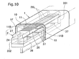
- a structure of an automobile functional component in embodiment 6 shown in Figs. 9 and 10 includes: a molded cover 1 formed by insert molding by using resin molded member 11 in which only a transmissive window portion for partially transmitting light is transparent or semi-transparent; a translucent film 1F for solid decorative molding of an entire surface of the molded cover 1; a plate-shaped light guide body 26 disposed close to a back side of the transparent or semi-transparent resin molded member 11 of the molded cover 1 to guide the light to a side of the transparent or semi-transparent resin molded member 11; a light-emitting source 27 disposed on a side face side of the light guide body 26 to incident into the light guide body 26; and extension wires 24 electrically connected to the light-emitting source 27 and extending from a side portion of the light guide body 26 ( Figs. 9 and 10 ).
- the molded cover 1 in embodiment 6 is formed by integrally molding opaque resin molded member 10 and the transparent or semi-transparent resin molded member 11 by insert molding. This is obtained by insert molding by cutting out a portion of the opaque resin molded member 1 and corresponding to a light-emitting area into a window shape and embedding the transparent or semi-transparent resin molded member 11, having a surface worked into a shape of a molded member for covering the light-emitting area, into the portion of the opaque resin molded member 1 formed by the cutting out.
- the transparent or semi-transparent resin molded member 11 is mounted into the notched window portion in the opaque resin molded member 10 to form a surface continuous with the opaque resin molded member 10 and, on the back side of the molded cover 1, is bent outward at positions near opposite side edges of the notched window portion to form protruding ribs 11B protruding downward.
- the protruding ribs 11B at the opposite side edges of the notched window portion extend along opposite sides of the notched window to form support frames for a surface-emitting device 6.
- a depressed face is formed between the protruding ribs 11B of the transparent resin molded member 11 and molded faces of Fresnel lenses 1F of the light guide body 26 are fitted in the depressed face. In this way, the light guide body 26 is securely positioned and light from the light guide body 26 can be reliably taken into a side of the transparent resin molded member 11.
- the surface-emitting device 2 in embodiment 6 is integrally formed by the plate-shaped light guide body 26 having a side face as an incident face and an upper face as an emission face of the guided light and a light-emitting source retaining unit which is in contact with the incident face of the light guide body 26 and in which the light-emitting source 27 is embedded, the light guide body 26 and the light-emitting source retaining unit being adjacent to each other, in contact with each other, and continuous in a longitudinal direction of the rectangular plate-shaped light guide body 26 in the plan view.
- the light-emitting source 27 is housed in the flat cubic light-emitting source retaining unit and emits the light toward the side face of the light guide body 26 in a light-emitting direction toward the light guide body 26.
- the light guide body 26 is formed by a narrow and long rectangular plate-shaped body and has the face close to and facing the transparent or semi-transparent resin molded member 11 as a light guide face and the side face of the cube in contact with the light-emitting source retaining unit as the incident face.
- the Fresnel lenses 26L are formed on the upper face of the light guide body 26 and the light guide body 26 reflects and refracts the light from the side face in contact with the light-emitting source retaining portion in its rectangular parallelepiped shape, straightens the light through the upper face where the Fresnel lenses are formed, and emits the light in the direction of the light guide face which is the upper face of the light guide body 26, i.e., toward the transparent resin molded member 11.
- the support frame 3 in embodiment 6 includes an oblong and rectangular plate-shaped support structure 36 in a plan view on an upper face of which switching circuits 37 as sensor parts are disposed and the wiring hole which is formed near one end of the support structure 36 and through which various wires are inserted.
- the extension wires 24 of the light-emitting source 27 supported at a predetermined height are inserted through the wiring hole and connected to a switch circuit and a power supply provided in an automobile main body or the support structure 36.
- the support structure 36 is formed by a base plate which serves as a support base of the surface-emitting device 2, a first support frame 351 and a second support frame 352 respectively standing from a position close to one end of the base plate and a position close to the other end, and switching circuits 37 formed on a face of the base plate.
- the first support frame 351 and the second support frame 352 support the light guide body 26 and the light-emitting source 27 at the same height from the base plate on tip portions of the respective support frames.
- the first support frame 351 supports a housing unit of the light-emitting source 27 on its upper face and has an insertion hole, through which the extension wires 24 of the light-emitting source 27 are inserted, inside itself along a height direction.
- Fig. 9h is a partially-cutaway exploded perspective view showing the structure of the vehicle functional component in embodiment 6
- Fig. 10 is a partially-cutaway perspective view showing the structure of the vehicle functional component in embodiment 6.
- the automobile functional component in embodiment 6 as a whole forms the door handle shown in Fig. 12 .
- the switching circuits 37 carry out switching operation of unlocking or locking by means of electric contact of an operator with the door handle or an electromagnetic signal by an electronic key
- the light-emitting source 27 emits the light through an electric signal to the extension wires 24 and the guided and transmitted light is emitted in the notched window frame area on a handle surface.
- Fig. 11 is a partially-cutaway perspective view showing a structure of a vehicle functional component in embodiment 7 of the invention.
- Fresnel lenses 11L are formed on a depressed face on a back face of a transparent resin molded member 11 and the transparent resin molded member 11 emits light over an entire notched window portion on an upper face while straightening the light from a light guide face 26U of a light guide body 26.
- Other basic structures and usages are similar to those in embodiment 6.
- Fig. 12 shows examples of mounted states of vehicle functional components in embodiment 8 of the invention to an automobile door handle 1H, a side pillar 1P, and a body side molding 1M.
- Fig. 12 shows, as an example of application to the side pillar, an example in which a locked state display window 11A for displaying letters indicating a locked state and an unlocked state display window 11B for displaying letters indicating an unlocked state are mounted as transparent resin molded members 11 into a molded cover 1.
- a light guide body is disposed on a back side of the resin molded member 11 of the locked state display window 11A and a locked-time light-emitting source 27A is provided beside the light guide body.
- a light guide body is disposed on a back side of the resin molded member 11 of the unlocked state display window 11B for displaying the letters indicating the unlocked state and an unlocked-time light-emitting source 27B is provided beside the light guide body.
- Figs. 13 (a) and 13 (b) show examples of mounted states of vehicle functional components in embodiment 9 of the invention to a front grille 1GL and an emblem 1E.
- a central portion of each grille bar of the front grille is molded into a notched window shape
- a transparent resin molded member 11 is fitted into the notched window portion
- a light guide body 26 is fitted immediately behind the resin molded member 11 while sandwiched between upper and lower protruding ribs 11B of the transparent resin molded member 11.
- a portion around an emblem molded portion E and inside a frame is formed as a transparent window and a surface-emitting device having surface light-emitting sources arranged in vertical and horizontal directions is mounted into a back side of the portion.
- Fig. 14 shows examples of mounted states of vehicle functional components in embodiment 10 of the invention to a rear garnish 1GN, a plate frame 1PF, and an emblem 1E.
- vehicle functional components are not necessarily mounted but a part thereof may be mounted. Portions for emitting the light and timing of the light emission are adjusted properly according to a shape of the vehicle functional component.
- the invention is not limited to the above-described embodiments and can be changed in various ways without departing from the gist of the invention.
- various techniques e.g., combination of partial structures of the respective embodiments, selection of the light-emitting areas or change in the form of the light emission, omission of the light transmissive film 4 or change in whether or not the light transmissive film 4 is disposed, change in whether or not the functional component is housed, change in the masking method, change in a shape of the molded cover 1, and change in material of the support frame 3 or solid decorative molding of the support frame 3 itself.
- the support frame 3 forms one of the automobile door handle, the side pillar, and the body side molding while covered with the molded cover 1.
- the sensor part senses the opening/closing operational signal of the automobile door key based on conductive contact with the molded cover 1 or the support frame 3.
- the support frame 3 forms one of the automobile door mirror, the rear garnish, and the indicator light cover while covered with the molded cover 1.
- the sensor part senses the operational signal of opening/closing operation of the automobile door from the user or the operational signal of operation of the turn signal from the user.
- the molded cover 1 is vacuum formed by molding the entire surface of the partially colored transparent or colorless transparent resin molded member by solid decorative molding by using the translucent film.
- the surface-emitting device 2 is disposed on the back side of the colored transparent or colorless transparent portion of the resin molded member, the remaining portion of the resin molded member excluding the colored transparent or colorless transparent molded face is formed to be non-translucent, and the non-translucent structure restricts the light-emitting area of the surface-emitting device 2.
- the masking member 5 from which the shape of the light-emitting area is cut out may be brought into contact with the back face of the molded cover 1.
- the transparent or semi-transparent resin molded member 11, formed into the shape of the light-emitting area may be formed by embedding/integrating molding into the cutout portion of the opaque resin molded member 1 from which the shape of the light-emitting area is cut out.
Landscapes
- Engineering & Computer Science (AREA)
- Mechanical Engineering (AREA)
- General Engineering & Computer Science (AREA)
- Physics & Mathematics (AREA)
- Microelectronics & Electronic Packaging (AREA)
- Optics & Photonics (AREA)
- Lighting Device Outwards From Vehicle And Optical Signal (AREA)
- Vehicle Interior And Exterior Ornaments, Soundproofing, And Insulation (AREA)
- Arrangement Of Elements, Cooling, Sealing, Or The Like Of Lighting Devices (AREA)
- Non-Portable Lighting Devices Or Systems Thereof (AREA)
- Arrangements Of Lighting Devices For Vehicle Interiors, Mounting And Supporting Thereof, Circuits Therefore (AREA)
Abstract
Description
- The present invention relates to a vehicle functional component, such as an automobile door mirror, a mirror cover, a rearview mirror for a motorcycle, an automobile door handle, a mounting frame for a door handle, an oil filler cover, an exposed oil filler cap, a grille, side pillars (an A-pillar, a B-pillar, and a C-pillar), a body side molding, a rear garnish, an emblem, a plate frame, an antenna, a fender, an indicator light cover, various meters, and various control levers, which exerts a function when it is attached to a main body or a part of the main body of an automobile or a motorcycle or a vehicle functional component forming an exterior part of an automobile or a motorcycle, and especially one having a light-emitting function inside thereof.
- Conventionally, as a functional component for an automobile, there is disclosed an automobile auxiliary direction indicator-cum-side irradiation device including: an auxiliary direction indicator connected to a turn signal switch to blink at a lower portion of a door mirror mounting base; a plastic cover which allows irradiation light of the auxiliary direction indicator to pass through itself to the outside and which extends from a front face to a side face around part of a back face; and a side marker light and an irradiating portion for applying light from a light-emitting irradiating body connected to an input of a back gear to light up on a back face (see Patent Document 1). This auxiliary direction indicator can be blinked in a higher position than a normal direction indicator and in a position out of a vehicle width, which facilitates visibility to surrounding vehicles and pedestrians. Moreover, because especially an area around a rear wheel is brightly irradiated during reverse traveling at nighttime, in a dark place, or in the rain, it is possible to reliably carry out putting into a garage, parking, and turning around of a vehicle.
- Patent Document 1:
JP 3100024 U - However, the conventional door mirror is combined with a light-emitting block formed separately to obtain a light-emitting function of the vehicle functional component. Such a door mirror requires a relatively complicated structure, because it is necessary to secure a space for housing the light-emitting block in order to obtain the light-emitting function. Furthermore, because the members are formed separately, it impairs design of the vehicle functional component itself. Therefore, the door mirror is not necessarily excellent in beauty or appearance.
- Therefore, it is an object of the present invention to provide a vehicle functional component which can obtain its light-emitting function with a relatively simple structure and in a relatively compact form, design of which is not impaired, and which is excellent in beauty and appearance.
- To solve the above problems, the present invention employs the following means (1) to (12).
- (1) A vehicle functional component of the present invention includes
a molded cover (1) molded into a shape of a surface of a part attached to a vehicle and
a surface-emitting device (2) bonded or fitted and fixed along a back face of the molded cover (1),
wherein the molded cover (1) is vacuum formed by solid decorative molding of a translucent resin molded member with a translucent film, and
light from the surface-emitting device (2) is transmitted through the molded cover (1) and emerges in a predetermined light-emitting area which is a part of a surface of a vehicle component. - (2) In the vehicle component according to the above, preferably, the molded cover (1) is provided to cover a surface of a support frame (3) mounted to a vehicle main body and
the surface-emitting device (2) is supported on a stay (31/351, 352) formed inside the support frame (3) and fixed into the support frame (3) while kept at a distance from the molded cover (1). - (3) In the vehicle component according to any of the above, preferably, a light transmissive film (4) having a light diffusion effect is disposed between a back face side of the molded cover (1) and a surface side of the surface-emitting device (2) and the light from the surface-emitting device (2) passes through the light transmissive film (4) and shines on a surface side of the molded cover (1) in a diffused state.
- (4) In the vehicle component according to any of the above, preferably, the surface-emitting device (2) includes a sheet-shaped board (21), a plurality of surface light-emitting sources (22) arranged on a surface side of the board (21), a board wire (23) installed on the board (21) across between the respective surface light-emitting sources (22), and an extension wire (24) electrically connected to the board wire (23) and extending from one end of the board (21),
the support frame (3) includes a housing space (32) for housing the board (21) and a wiring hole (33) which is formed close to one end of the housing space (32) and through which various wires are inserted, and
the extension wire (24) of the board (21) housed in the housing space (32) is inserted through the wiring hole (33) and connected to a switch circuit and a power supply provided in the vehicle main body or the housing space (32). - (5) In the vehicle component according to (4), preferably, the housing space (32) in the support frame (3) houses a sensor part for sensing a predetermined operational signal from a user together with the surface-emitting device (2) and
the switch circuit carries out switching operation in synchronization with the predetermined operational signal sensed by the sensor part to blink or light the surface-emitting device (2). - (6) In the vehicle component according to any of the above, preferably, the surface-emitting device (2) includes a plate-shaped light guide body (26) having an upper face as a light guide face, a light-emitting source (27) disposed on a side face side of the light guide body (26) to incident into the light guide body (26), and an extension wire (24) electrically connected to the light-emitting source (27) and extending from a side portion of the light guide body (26),
the support frame (3) includes a support structure (36) capable of supporting the light guide body (26) and the light-emitting source (27) respectively at predetermined heights and a wiring hole which is formed near one end of the support structure and through which various wires are inserted,
the extension wire (24) of the light-emitting source (27) supported at the predetermined height is inserted through the wiring hole and connected to a switch circuit and a power supply provided in the vehicle main body or the support structure (36). - (7) In the vehicle component according to (6), preferably, the support structure of the support frame (3) supports a sensor part for sensing a predetermined operational signal from a user together with the surface-emitting device (2) and
the switch circuit carries out switching operation in synchronization with the predetermined operational signal sensed by the sensor part to blink or light the surface-emitting device (2). - (8) In the vehicle component according to (5) or (7), preferably, the support frame (3) forms one of an automobile door handle, a side pillar, and a body side molding while covered with the molded cover (1), and
the sensor part senses an opening/closing operational signal of an automobile door key based on conductive contact with the molded cover (1) or the support frame (3). - (9) In the vehicle component according to (5) or (7), preferably, the support frame (3) forms one of an automobile door mirror, a rear garnish, and an indicator light cover while covered with the molded cover (1), and
the sensor part senses an opening/closing operational signal of an automobile door from the user or an operational signal of a turn signal from the user. - (10) In the vehicle component according to any of the above, preferably, the molded cover (1) is vacuum formed by solid decorative molding of an entire surface of a partially colored transparent or colorless transparent resin molded member with a translucent film,
the surface-emitting device (2) is disposed on a back side of the colored transparent or colorless transparent portion of the resin molded member,
a remaining portion of the resin molded member excluding the colored transparent or colorless transparent molded face is formed to be non-translucent, and
the non-translucent structure restricts the light-emitting area of the surface-emitting device (2). - (11) In the vehicle component according to any of the above, preferably, a masking member (5) from which a shape of the light-emitting area is cut out is brought into contact with the back face of the molded cover (1).
- (12) In the vehicle component according to any of the above, preferably, the resin molded member (11), being transparent or semi-transparent and formed into a shape of the light-emitting area, is formed by embedding/integrating molding into the cutout portion of the resin molded member (1) being opaque from which the shape of the light-emitting area is cut out.
- With the above-described means, by obtaining a light-emitting function of the vehicle functional component by transmissive light emission of the surface-emitting device provided inside the vehicle functional component itself, the structure combined with the light-emitting block in the prior art becomes unnecessary and it is possible to obtain the light-emitting function with the relatively simple and compact structure while saving space for housing the light-emitting body. Moreover, it is possible to provide the vehicle functional component excellent in beauty and appearance with a non-conventional light-emitting form.
-
- [
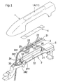
Fig.1] Fig. 1 is an exploded perspective view showing a structure of a vehicle functional component inembodiment 1 of the present invention. - [
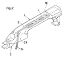
Fig. 2] Fig. 2 is a perspective view showing a light-emitting state of the vehicle functional component inembodiment 1. - [
Fig. 3] Fig. 3 is a perspective explanatory drawing showing constituent material of a moldedcover 1 used for the vehicle functional component inembodiment 1. - [
Fig. 4] Fig. 4 is a plan explanatory drawing of an example of a surface treatment pattern of a lighttransmissive film 4 used for the vehicle functional component inembodiment 1. - [
Fig. 5] Fig. 5 is a partially-cutaway perspective view of a vehicle functional component inembodiment 2 of the invention. [Fig. 6] Fig. 6 is a front view showing a mounted state of a vehicle functional component inembodiment 3 of the invention. - [
Figs. 7(a) and 7(b)] Figs. 7(a) and 7(b) are front views showing mounted states of a vehicle functional component inembodiment 4 of the invention in a first light-emitting state (Fig. 7(a) ) and a second light-emitting state (Fig. 7(b) ). - [
Fig. 8] Fig. 8 is a front view showing a mounted state of a vehicle functional component inembodiment 5 of the invention in a light-emitting state. - [
Fig. 9] Fig. 9 is a partially-cutaway exploded perspective view showing a structure of a vehicle functional component in embodiment 6 of the invention. - [
Fig. 10] Fig. 10 is a partially-cutaway perspective view showing the structure of the vehicle functional component in embodiment 6 of the invention. - [
Fig. 11] Fig. 11 is a partially-cutaway perspective view showing a structure of a vehicle functional component in embodiment 7 of the invention. - [
Fig. 12] Fig. 12 is a drawing showing mounted states of vehicle functional components in embodiment 8 of the invention to an automobile door handle, a side pillar, and a body side molding. - [
Figs. 13(a) and 13(b)] Figs. 13(a) and 13(b) are drawings showing mounted states of vehicle functional components in embodiment 9 of the invention to a front grille and an emblem. - [
Fig. 14] Fig. 14 is a drawing showing mounted states of vehicle functional components inembodiment 10 of the invention to a rear garnish, a plate frame, and an emblem. - Modes for carrying out the present invention will be described below with reference to
Figs. 1 to 4 showing a vehicle functional component inembodiment 1,Figs. 5 to 11 showing vehicle functional components inembodiments 2 to 7, andFigs. 12 to 14 showing examples of use of these vehicle functional components. In each of the embodiments, the vehicle functional component in the invention is basically formed by a moldedcover 1 molded into a shape of a surface of a part attached to an automobile and a surface-emittingdevice 2 bonded or inserted and fixed along a back face of the moldedcover 1. Light from the surface-emittingdevice 2 is transmitted through the moldedcover 1 and emerges as a transmissive light-emitting portion L at a portion of a surface of the vehicle functional component. As used herein, the vehicle includes a two-wheel vehicle, a four-wheel vehicle, a three-wheel vehicle, and also a motorized bicycle and includes a passenger vehicle and also a remotely-driven vehicle, a hand cart, and a tow truck. - The molded
cover 1 is provided to cover a surface of asupport frame 3 mounted to a vehicle main body. The surface-emitting device 2 (described next) is retained bystays 31 formed inside thesupport frame 3 and fixed into thesupport frame 3 while kept at a distance from the moldedcover 1. As used herein, the moldedcover 1 is a solid decorative molded article vacuum formed by decorative molding of a resin moldedmember 10, which is molded and made of translucent resin, with adecorative film 1F having translucency and is not subjected to electroforming treatment such as plating. In other words, although a conventional plated article is non-light transmissive member, it is possible to freely set whether or not thedecorative film 1F is made light transmissive and light transmittance by selecting the resin moldedmember 10 and thedecorative film 1F in the case of the moldedcover 1 having a surface vacuum formed by solid decorative molding with thedecorative film 1F. A light transmitting area from the moldedcover 1 can be controlled by masking treatment of the moldedcover 1 or embedding/integrating molding of an opaque resin molded member and a transparent resin molded member and also by a light-emitting position, a light-emitting direction, and directional characteristics (light-emitting area) of the surface-emittingdevice 2. The masking treatment mentioned herein includes various methods such as formation of an opaque coating on a surface or a back face of the moldedcover 1, covering of the back face of the moldedcover 1 with a maskingmember 5, adjustment of the thickness of the moldedcover 1 itself, i.e., formation of a thick-walled portion or a rib, and formation of a stud or a rib for fitting. The embedding molding of the opaque resin molded member and the transparent resin molded member includes punching a portion of the opaque resin molded member into a shape of a light-emitting area, and embedding the transparent resin molded member into the punched portion to be molded. The integrating molding includes integration of the opaque resin molded member, a portion of which is punched into the shape of the light-emitting area, and the transparent resin molded member molded in advance into a shape of the punched portion. - The surface-emitting
device 2 is a light-emitting body for emitting light to a curved or flat light distribution face and includes a member formed by a flat light-emitting body having a base with a curved or flat light distribution face and one or a plurality of light-emitting device (s) disposed on the light distribution face of the base and also includes a member formed by a light guide body with a light-emitting source and having a plate-shapedlight guide body 26, which has a side face as an incident face and an upper face as an emission surface of guided light, and a light-emittingsource 27 disposed on the incident face of thelight guide body 26 to incident into thelight guide body 26, for example. The light from the light-emitting device(s) is distributed to an upper face side with respect to a face on which the device lies and expands over the upper face. Because the light is less likely to come around to a back side of the light distribution face, it is easy to secure an amount of light from the light-emitting device (s) to the light distribution face side. Moreover, by forming the base into a thin plate shape or a thin film shape, it is easy to make the surface-emittingdevice 2 compact. If the base itself has flexibility, it is easy to deform the surface-emittingdevice 2 along a molded face of the moldedcover 1. The surface-emittingdevice 2 is disposed with its light distribution face facing the back face of the moldedcover 1. As used herein, the light distribution face is preferably formed along the back face of the moldedcover 1 to be parallel thereto and arranged at a predetermined or longer distance from the back face of the molded cover. The light transmitting area from the surface-emittingdevice 2 to the moldedcover 1 is controlled by direct masking treatment of the surface-emittingdevice 2. As used herein, the masking treatment of the surface-emittingdevice 2 includes various methods such as covering of the surface-emittingdevice 2 with a maskingmember 5 with or without contact between them, formation of a coating by coloring of a device cover, and disposition of a light shielding plate (including a light shielding sheet and a light shielding film) between the surface-emitting device 12 and the moldedcover 1. - The surface-emitting
device 2 may be integrally formed by a plate-shapedlight guide body 26 having a side face as an incident face and an upper face as an emission face of guided light and a light-emitting source retaining portion which is in contact with the incident face of thelight guide body 26 and in which a light-emittingsource 27 is embedded, thelight guide body 26 and the light-emitting source retaining portion being adjacent to and in contact with each other and arranged side by side in a longitudinal direction of thelight guide body 26 which is in a rectangular plate shape in a plan view (seeFigs. 9 ,10 , and11 ). In this case, the light-emittingsource 27 radiates and emits light sideway toward a side face of the light guide body, the light is refracted and reflected in the light guide body, and an entire upper face of the light guide body emits the light. - The
support frame 3 is a partial constituent member for supporting the moldedcover 1 with the frame when the moldedcover 1 is provided to cover an open upper face or side face of thesupport frame 3 and forms the vehicle functional component together with the moldedcover 1 while covered with the moldedcover 1. - As used herein, the vehicle functional component in the invention refers to an attached member other than a light-emitting part and for exerting some function, when it is attached to an outer side of or inside a main body of an automobile or a motorcycle, and includes exterior equipment such as an automobile door mirror, a rearview mirror for a motorcycle, an automobile door handle, a mounting frame (depressed frame portion D2) for a door handle, a fender, a grille, an oil filler cover, an exposed oil filler cap, a mirror cover, an exposed oil filler cap, side pillars (an A-pillar, a B-pillar, and a C-pillar), a body side molding, a rear garnish, an emblem, a plate frame, an antenna, an indicator light cover, and an antenna and exterior and interior equipment such as various meters and various control levers. Some function includes aesthetic and non-aesthetic visibility functions, protective functions, opening and closing/locking functions of various doors, and the like.
- The
support frame 3 includes, inside itself, ahousing space 32 for housing the light-emittingdevice 2 together with the functional component for performing some function described above and also includes a mounting portion to the vehicle main body. In thehousing space 32, the surface-emittingdevice 2 is housed to be exposed at least to a portion of a side portion or an upper portion of the functional component. In thehousing space 32, awiring hole 33 communicating with and opening into the vehicle main body through the mounting portion is formed. Wires for the functional component housed in thehousing space 32 and wires for light emission of the surface-emittingdevice 2 are inserted through thewiring hole 33. - The
housing space 32 may house a sensor part for sensing a predetermined operational signal from a user together with the surface-emittingdevice 2. A switch circuit carries out switching operation in synchronization with an opening/closing operation signal of a key received by the sensor part to blink or light the surface-emittingdevice 2. In this case,extension wires 24 of the surface-emittingdevice 2 are inserted through thewiring hole 33 and connected to the switch circuit and a power supply in the vehicle main body. - As another structure, the
support frame 3 itself may form one of an automobile door handle, a side pillar, and a body side molding while covered with the moldedcover 1. In this case, the sensor part may sense the opening/closing operation signal of an automobile door key based on conductive contact with the moldedcover 1 or thesupport frame 3. - As yet another structure, the
support frame 3 itself may form one of an automobile door mirror, a rear garnish, and an indicator light cover while covered with the moldedcover 1. In this case, the sensor part may sense the operational signal of opening/closing operation of an automobile door by a user or an operational signal of operation of a turn signal from a user. - The switch circuit and/or the power supply may be housed in the
housing space 32. In this case, wires for the power supply are not inserted through thewiring hole 33 and only a connecting line for sending an operation instruction signal or an operation signal of the functional component is inserted through thewiring hole 33 so that the vehicle main body and the functional component are electrically connected. - If needed, the
light transmissive film 4 having a light diffusion effect may be disposed between the back face side of the moldedcover 1 and a surface side of the surface-emittingdevice 2. If thelight transmissive film 4 is disposed, the light from the surface-emittingdevice 2 passes through thelight transmissive film 4 and shines on the surface side of the moldedcover 1 in a diffused state. With the light diffusion effect of thelight transmissive film 4, it is possible to secure a proper degree of diffusion of the light source, even though the surface-emittingdevice 2 is close to the moldedcover 1. As used herein, the light diffusion effect includes lens effects due to lens working of a surface or a back face of the film and effects due to various types of working such as random dent (emboss) working, molding by mixture or adhesion of translucent diffusing particles into an inner face or respective faces of the film, formation of steps or a corrugated face by deformation of the film itself, and coating of the surface with a diffusive fixing agent. Moreover, as for thelight transmissive film 4, a sheet-shaped or plate-shaped film is included irrespective of the thickness. Furthermore, a single-layer film and also a multi-layer molded film made of the same or different materials are included. Moreover, if a part of thelight transmissive film 4 is masked, it is possible to restrict a light transmitting area. If thelight transmissive film 4 is subjected to polarization treatment, it is possible to restrict part of the diffusion effect. Respective structures in the embodiments will be specifically described below. - The vehicle functional component in
embodiment 1 shown inFigs. 1 to 4 forms an automobile door handle by covering thesupport frame 3 with the moldedcover 1. For example, the door handle is configured such that an electric key K (not shown) for opening and closing is included in theinner housing space 32, a narrow and long sheet-shaped surface-emittingdevice 2 formed by successively arranging surface light-emittingsources 22 formed by LED devices in a line is disposed on an upper face side of the electric key K, and thelight transmissive film 4 having a surface corrugated in a predetermined pattern shown inFig. 4 , for example, is disposed along the light distribution face which is an upper face of the surface-emittingdevice 2. The surface-emittingdevice 2 and thelight transmissive film 4 are substantially in the same shapes and molded into narrow and long rectangular shapes along an extending upper face of a door handle shape of the moldedcover 1. - The surface-emitting
device 2 inembodiment 1 includes a sheet-shapedboard 21, the plurality of surface light-emittingsources 22 arranged in a line on a surface side of theboard 21,board wires 23 installed on theboard 21 across between the respective surface light-emittingsources 22, and theextension wires 24 electrically connected to theboard wires 23 and extending from one end of theboard 21. The surface light-emittingsources 22 are formed by the LED light-emitting devices arranged planarly in rectangular frames and respective upper faces of the rectangular frames of the respective devices are covered with transparent lens covers in shapes of spherical caps and have light diffusion properties due to the lens effects of the lens covers. - In
embodiment 1, thewiring hole 32 is formed in a position close to one end of the oblong prism-shapedhousing space 32 and corresponding to one of mounting leg portions of thesupport frame 3 to be mounted to the vehicle main body. Theextension wires 24 of the surface-emittingdevice 2 are inserted through thewiring hole 32. - As shown in
Fig. 2 , a maskingmember 5 having a cover end facing the surface-emittingdevice 2 is attached to one end portion of thehousing space 32 in the retainingframe 3 and thecover end 5E of the maskingmember 5 exerts a masking effect as one end edge of a light-emitting area. Thecover end 5E is formed by cutting (punching) the end portion of the maskingmember 5 straight and the straight portion comes in contact with the back face of the moldedcover 1 to form a masking end edge. The two stays 31 for retaining one end of the surface-emittingdevice 2 are formed to stand parallel in thehousing space 32 at the one end portion of thehousing space 32 in the retainingframe 3 and on an inner side of thecover end 5E. Upper ends of thestays 31 are molded into semicircular curved shapes and mounting base portions of thestays 31 are close to thecover end 5E. At the other end portion of thehousing space 32 in the retainingframe 3, first retaining frames 341 and second retaining frames 342 for retaining the other end of the surface light-emitting device are formed to face an inside of thehousing space 32 and to face each other, respectively. Because the first retaining frames 341 and the second retaining frames 342 are formed at small intervals in a longitudinal direction of the housing space, i.e. , a longitudinal direction of the door handle,grooves 34 are formed between the frames. The one end portion of theboard 21 of the surface-emittingdevice 2 may be bent, inserted, and fixed into thegrooves 34. - As shown in
Fig. 3 , in the vehicle functional component inembodiment 1, the moldedcover 1 is vacuum formed by solid decorative molding of a surface of a colored transparent or colorless transparent resin molded member with a plating-like translucent film. On a back side of a molded face of the resin molded member inembodiment 1, coatings of dark (black) paint are partially formed as non-translucent coating layers 1M around a position where the surface-emittingdevice 2 is disposed. With the coating layers 1M, the light-emitting area of the surface-emittingdevice 2 is masked and light emission is intercepted in unnecessary areas. - On the surface of the
transmissive film 4 inembodiment 1, three-dimensional lens portions in the same polygonal pyramid shapes are arranged and molded in a pattern in length and width directions as shown inFig. 4 , for example. - The surface-emitting
device 2 inembodiment 1 formed in this manner emits light a predetermined times at the time of unlocking and locking, when the light-emitting switch operates in synchronization with key opening and closing operations of the electric key K which is the functional component housed inside. When the light is emitted, the transmissive light-emitting portion L formed of successive circles shown inFig. 2 emerges in a line on an outer face of the moldedcover 1. - In a vehicle functional component in
embodiment 2 shown inFig. 5 , thesupport frame 3 forms an automobile door mirror while covered with the moldedcover 1 and the sensor part housed in the housing space together with the surface-emittingdevice 2 senses the opening and closing operational signals of the automobile door or the turn signal operational signal from a user. Other structures, usages, and states of use which are not especially described are similar to those inembodiment 1. - In a vehicle functional component in
embodiment 3 shown inFig. 6 , thesupport frame 3 forms an automobile door handle of each of a rear door and a front door while covered with the moldedcover 1 and the sensor part housed in the housing space together with the surface-emittingdevice 2 senses the opening and closing operational signals of the automobile door or the turn signal operational signal from a user. InFig. 6 , oblong and narrow rectangular stick-shaped transmissive light-emitting portion L for each of the rear door and the front door is projected at the same height. Other structures, usages, and states of use which are not especially described are similar to those inembodiment 1. - In a vehicle functional component in
embodiment 4 shown inFigs. 7 (a) and 7 (b) , thesupport frame 3 forms an automobile door handle while covered with the moldedcover 1 and the sensor part housed in the housing space together with the surface-emittingdevice 2 senses the opening and closing operational signals of the automobile door or the turn signal operational signal from a user. Especially in the embodiment, as shown inFigs. 7 (a) and 7(b) , it is possible to achieve two light-emitting states, i.e. , the light-emitting state of first transmissive light-emitting areas LA, in which only first surface light-emittingdevices 22A molded successively in groups of three out of the surface light-emittingdevices 22 arranged successively emit light as shown inFig. 7 (a) , and the light-emitting state of second transmissive light-emitting areas LB, in which only second surface light-emittingdevices 22B each disposed alone between the first surface light-emittingdevices 22A at an interval out of the surface light-emittingdevices 22 arranged successively emit light as shown inFig. 7(b) . For example, by emitting the light while switching between the light-emitting states inFig. 7(a) and Fig. 7 (b) at the time of locking and unlocking of the automobile key, locking and unlocking operations can be clearly distinguished from each other and recognized. Reference characters DS inFigs. 7 (a) and 7 (b) designate contact switches and unlocking can be carried out by simultaneously gripping both the switch portions for energization. Other structures, usages, and states of use which are not especially described are similar to those inembodiment 1. - The
support frame 3 inembodiment 5 shown inFig. 8 forms an automobile door handle while covered with the moldedcover 1. The sensor part inembodiment 5 has one of contact switches exposed as a portion of the molded cover and, when the moldedcover 1 itself is in a conductive contact with the contact switch to come into a conductive state, senses opening and closing operational signals of an automobile door key. To put it concretely, a movable portion and an immovable portion of the door handle are arranged in a horizontal direction in a front view and the rectangular contact switch DS is exposed on the portion of the moldedcover 1 of the movable portion. A surface portion of the moldedcover 1, which is the movable portion, excluding the contact switch DS or a surface portion of the entire molded cover of the immovable portion is the other contact switch. When the one contact switch DS comes in contact with the other contact switch while in contact with a hand of a human body, the sensor part comes into the conductive state to sense the opening/closing signal. - In
embodiment 5, the entire moldedcover 1 of the movable portion excluding a left end is formed as a transmissive light-emitting portion L and the entire transmissive light-emitting portion L has light diffusion effect and reflects and projects light in a diagonal lattice pattern. Inembodiment 5, a door depression is formed by a reflector D2 and the light is reflected by the reflector D2 of the depressed face when the surface-emittingdevice 2 emits the light. Other structures, usages, and states of use which are not especially described are similar to those inembodiment 1. - A structure of an automobile functional component in embodiment 6 shown in
Figs. 9 and10 includes: a moldedcover 1 formed by insert molding by using resin moldedmember 11 in which only a transmissive window portion for partially transmitting light is transparent or semi-transparent; atranslucent film 1F for solid decorative molding of an entire surface of the moldedcover 1; a plate-shapedlight guide body 26 disposed close to a back side of the transparent or semi-transparent resin moldedmember 11 of the moldedcover 1 to guide the light to a side of the transparent or semi-transparent resin moldedmember 11; a light-emittingsource 27 disposed on a side face side of thelight guide body 26 to incident into thelight guide body 26; andextension wires 24 electrically connected to the light-emittingsource 27 and extending from a side portion of the light guide body 26 (Figs. 9 and10 ). - The molded
cover 1 in embodiment 6 is formed by integrally molding opaque resin moldedmember 10 and the transparent or semi-transparent resin moldedmember 11 by insert molding. This is obtained by insert molding by cutting out a portion of the opaque resin moldedmember 1 and corresponding to a light-emitting area into a window shape and embedding the transparent or semi-transparent resin moldedmember 11, having a surface worked into a shape of a molded member for covering the light-emitting area, into the portion of the opaque resin moldedmember 1 formed by the cutting out. The transparent or semi-transparent resin moldedmember 11 is mounted into the notched window portion in the opaque resin moldedmember 10 to form a surface continuous with the opaque resin moldedmember 10 and, on the back side of the moldedcover 1, is bent outward at positions near opposite side edges of the notched window portion to form protrudingribs 11B protruding downward. The protrudingribs 11B at the opposite side edges of the notched window portion extend along opposite sides of the notched window to form support frames for a surface-emitting device 6. In embodiment 6, a depressed face is formed between theprotruding ribs 11B of the transparent resin moldedmember 11 and molded faces ofFresnel lenses 1F of thelight guide body 26 are fitted in the depressed face. In this way, thelight guide body 26 is securely positioned and light from thelight guide body 26 can be reliably taken into a side of the transparent resin moldedmember 11. - The surface-emitting
device 2 in embodiment 6 is integrally formed by the plate-shapedlight guide body 26 having a side face as an incident face and an upper face as an emission face of the guided light and a light-emitting source retaining unit which is in contact with the incident face of thelight guide body 26 and in which the light-emittingsource 27 is embedded, thelight guide body 26 and the light-emitting source retaining unit being adjacent to each other, in contact with each other, and continuous in a longitudinal direction of the rectangular plate-shapedlight guide body 26 in the plan view. The light-emittingsource 27 is housed in the flat cubic light-emitting source retaining unit and emits the light toward the side face of thelight guide body 26 in a light-emitting direction toward thelight guide body 26. Thelight guide body 26 is formed by a narrow and long rectangular plate-shaped body and has the face close to and facing the transparent or semi-transparent resin moldedmember 11 as a light guide face and the side face of the cube in contact with the light-emitting source retaining unit as the incident face. TheFresnel lenses 26L are formed on the upper face of thelight guide body 26 and thelight guide body 26 reflects and refracts the light from the side face in contact with the light-emitting source retaining portion in its rectangular parallelepiped shape, straightens the light through the upper face where the Fresnel lenses are formed, and emits the light in the direction of the light guide face which is the upper face of thelight guide body 26, i.e., toward the transparent resin moldedmember 11. - The
support frame 3 in embodiment 6 includes an oblong and rectangular plate-shapedsupport structure 36 in a plan view on an upper face of which switchingcircuits 37 as sensor parts are disposed and the wiring hole which is formed near one end of thesupport structure 36 and through which various wires are inserted. Theextension wires 24 of the light-emittingsource 27 supported at a predetermined height are inserted through the wiring hole and connected to a switch circuit and a power supply provided in an automobile main body or thesupport structure 36. To put it concretely, thesupport structure 36 is formed by a base plate which serves as a support base of the surface-emittingdevice 2, afirst support frame 351 and asecond support frame 352 respectively standing from a position close to one end of the base plate and a position close to the other end, and switchingcircuits 37 formed on a face of the base plate. Thefirst support frame 351 and thesecond support frame 352 support thelight guide body 26 and the light-emittingsource 27 at the same height from the base plate on tip portions of the respective support frames. Thefirst support frame 351 supports a housing unit of the light-emittingsource 27 on its upper face and has an insertion hole, through which theextension wires 24 of the light-emittingsource 27 are inserted, inside itself along a height direction. -
Fig. 9h is a partially-cutaway exploded perspective view showing the structure of the vehicle functional component in embodiment 6 andFig. 10 is a partially-cutaway perspective view showing the structure of the vehicle functional component in embodiment 6. The automobile functional component in embodiment 6 as a whole forms the door handle shown inFig. 12 . When the switchingcircuits 37 carry out switching operation of unlocking or locking by means of electric contact of an operator with the door handle or an electromagnetic signal by an electronic key, the light-emittingsource 27 emits the light through an electric signal to theextension wires 24 and the guided and transmitted light is emitted in the notched window frame area on a handle surface. -
Fig. 11 is a partially-cutaway perspective view showing a structure of a vehicle functional component in embodiment 7 of the invention. In embodiment 7,Fresnel lenses 11L are formed on a depressed face on a back face of a transparent resin moldedmember 11 and the transparent resin moldedmember 11 emits light over an entire notched window portion on an upper face while straightening the light from alight guide face 26U of alight guide body 26. Other basic structures and usages are similar to those in embodiment 6. -
Fig. 12 shows examples of mounted states of vehicle functional components in embodiment 8 of the invention to anautomobile door handle 1H, aside pillar 1P, and abody side molding 1M.Fig. 12 shows, as an example of application to the side pillar, an example in which a lockedstate display window 11A for displaying letters indicating a locked state and an unlockedstate display window 11B for displaying letters indicating an unlocked state are mounted as transparent resin moldedmembers 11 into a moldedcover 1. A light guide body is disposed on a back side of the resin moldedmember 11 of the lockedstate display window 11A and a locked-time light-emittingsource 27A is provided beside the light guide body. A light guide body is disposed on a back side of the resin moldedmember 11 of the unlockedstate display window 11B for displaying the letters indicating the unlocked state and an unlocked-time light-emittingsource 27B is provided beside the light guide body. -
Figs. 13 (a) and 13 (b) show examples of mounted states of vehicle functional components in embodiment 9 of the invention to a front grille 1GL and anemblem 1E. In a sectional view inFig. 13 (b) , a central portion of each grille bar of the front grille is molded into a notched window shape, a transparent resin moldedmember 11 is fitted into the notched window portion, and alight guide body 26 is fitted immediately behind the resin moldedmember 11 while sandwiched between upper and lower protrudingribs 11B of the transparent resin moldedmember 11. In the emblem, a portion around an emblem molded portion E and inside a frame is formed as a transparent window and a surface-emitting device having surface light-emitting sources arranged in vertical and horizontal directions is mounted into a back side of the portion. -
Fig. 14 shows examples of mounted states of vehicle functional components inembodiment 10 of the invention to a rear garnish 1GN, a plate frame 1PF, and anemblem 1E. However, these are merely examples of application of the invention and all the vehicle functional components are not necessarily mounted but a part thereof may be mounted. Portions for emitting the light and timing of the light emission are adjusted properly according to a shape of the vehicle functional component. - The invention is not limited to the above-described embodiments and can be changed in various ways without departing from the gist of the invention. For example, it is possible to combine various techniques, e.g., combination of partial structures of the respective embodiments, selection of the light-emitting areas or change in the form of the light emission, omission of the
light transmissive film 4 or change in whether or not thelight transmissive film 4 is disposed, change in whether or not the functional component is housed, change in the masking method, change in a shape of the moldedcover 1, and change in material of thesupport frame 3 or solid decorative molding of thesupport frame 3 itself. - For example, the
support frame 3 forms one of the automobile door handle, the side pillar, and the body side molding while covered with the moldedcover 1. In this case, the sensor part senses the opening/closing operational signal of the automobile door key based on conductive contact with the moldedcover 1 or thesupport frame 3. Thesupport frame 3 forms one of the automobile door mirror, the rear garnish, and the indicator light cover while covered with the moldedcover 1. In this case, the sensor part senses the operational signal of opening/closing operation of the automobile door from the user or the operational signal of operation of the turn signal from the user. In the vehicle functional component in any of the above-described embodiments, the moldedcover 1 is vacuum formed by molding the entire surface of the partially colored transparent or colorless transparent resin molded member by solid decorative molding by using the translucent film. Preferably, the surface-emittingdevice 2 is disposed on the back side of the colored transparent or colorless transparent portion of the resin molded member, the remaining portion of the resin molded member excluding the colored transparent or colorless transparent molded face is formed to be non-translucent, and the non-translucent structure restricts the light-emitting area of the surface-emittingdevice 2. Moreover, the maskingmember 5 from which the shape of the light-emitting area is cut out may be brought into contact with the back face of the moldedcover 1. It is also possible that the transparent or semi-transparent resin moldedmember 11, formed into the shape of the light-emitting area, may be formed by embedding/integrating molding into the cutout portion of the opaque resin moldedmember 1 from which the shape of the light-emitting area is cut out. -
- 1
- molded cover
- 1F
- decorative film
- 10
- opaque resin molded member
- 11
- transparent or semi-transparent resin molded member
- 2
- surface-emitting device
- 21
- board
- 22
- surface light-emitting source
- 22A
- first surface light-emitting source
- 22B
- second surface light-emitting source
- 22C
- lens cover
- 23
- board wire
- 24
- extension wire
- 26
- light guide body
- 27
- light-emitting source
- 3
- support frame
- 3L
- frame side plate
- 31
- stay
- 32
- housing space
- 33
- wiring hole
- 36
- support structure
- 4
- light transmissive film
- 5
- masking member
- 5K
- door key (cylinder head)
- DS
- contact switch
- L
- transmissive light-emitting portion, reflective light-emitting portion
Claims (12)
- A vehicle component comprising:a molded cover (1) molded into a shape of a surface of a part attached to a vehicle; anda surface-emitting device (2) bonded or fitted and fixed along a back face of the molded cover (1),wherein the molded cover (1) is vacuum formed by solid decorative molding of a translucent resin molded member with a translucent film, andlight from the surface-emitting device (2) is transmitted through the molded cover (1) and emerges in a predetermined light-emitting area which is a part of a surface of the vehicle component.
- The vehicle component according to claim 1,
wherein the molded cover (1) is provided to cover a surface of a support frame (3) mounted to a vehicle main body and
the surface-emitting device (2) is supported on a stay (31/351, 352) formed inside the support frame (3) and fixed into the support frame (3) while kept at a distance from the molded cover (1). - The vehicle component according to claim 1 or 2,
wherein a light transmissive film (4) having a light diffusion effect is disposed between a back face side of the molded cover (1) and a surface side of the surface-emitting device (2) and the light from the surface-emitting device (2) passes through the light transmissive film (4) and shines on a surface side of the molded cover (1) in a diffused state. - The vehicle functional component according to any one of claims 1 to 3,
wherein the surface-emitting device (2) includes a sheet-shaped board (21), a plurality of surface light-emitting sources (22) arranged on a surface side of the board (21), a board wire (23) installed on the board (21) across between the respective surface light-emitting sources (22), and an extension wire (24) electrically connected to the board wire (23) and extending from one end of the board (21),
the support frame (3) includes a housing space (32) for housing the board (21) and a wiring hole (33) which is formed close to one end of the housing space (32) and through which various wires are inserted, and
the extension wire (24) of the board (21) housed in the housing space (32) is inserted through the wiring hole (33) and connected to a switch circuit and a power supply provided in the vehicle main body or the housing space (32). - The vehicle functional component according to claim 4,
wherein the housing space (32) in the support frame (3) houses a sensor part for sensing a predetermined operational signal from a user together with the surface-emitting device (2) and
the switch circuit carries out switching operation in synchronization with the predetermined operational signal sensed by the sensor part to blink or light the surface-emitting device (2). - The vehicle functional component according to any one of claims 1 to 3,
wherein the surface-emitting device (2) includes a plate-shaped light guide body (26) having an upper face as a light guide face, a light-emitting source (27) disposed on a side face side of the light guide body (26) to incident into the light guide body (26), and an extension wire (24) electrically connected to the light-emitting source (27) and extending from a side portion of the light guide body (26),
the support frame (3) includes a support structure (36) capable of supporting the light guide body (26) and the light-emitting source (27) respectively at predetermined heights and a wiring hole which is formed near one end of the support structure and through which various wires are inserted,
the extension wire (24) of the light-emitting source (27) supported at the predetermined height is inserted through the wiring hole and connected to a switch circuit and a power supply provided in the vehicle main body or the support structure (36) . - The vehicle functional component according to claim 6,
wherein the support structure of the support frame (3) supports a sensor part for sensing a predetermined operational signal from a user together with the surface-emitting device (2) and
the switch circuit carries out switching operation in synchronization with the predetermined operational signal sensed by the sensor part to blink or light the surface-emitting device (2). - The vehicle functional component according to claim 5 or 7, wherein the support frame (3) forms one of an automobile door handle, a mounting frame for a door handle, a side pillar, and a body side molding while covered with the molded cover (1), and
the sensor part senses an opening/closing operational signal of an automobile door key based on conductive contact with the molded cover (1) or the support frame (3). - The vehicle functional component according to claim 5 or 7, wherein the support frame (3) forms one of an automobile door mirror, a rear garnish, and an indicator light cover while covered with the molded cover (1), and
the sensor part senses an opening/closing operational signal of an automobile door from the user or an operational signal of a turn signal from the user. - The vehicle functional component according to any one of claims 1 to 9,
wherein the molded cover (1) is vacuum formed by solid decorative molding of an entire surface of a partially colored transparent or colorless transparent resin molded member with a translucent film,
the surface-emitting device (2) is disposed on a back side of the colored transparent or colorless transparent portion of the resin molded member,
a remaining portion of the resin molded member excluding the colored transparent or colorless transparent molded face is formed to be non-translucent, and
the non-translucent structure restricts the light-emitting area of the surface-emitting device (2). - The vehicle functional component according to any one of claims 1 to 10, wherein a masking member (5) from which a shape of the light-emitting area is cut out is brought into contact with the back face of the molded cover (1).
- The vehicle functional component according to any one of claims 1 to 10, wherein the resin molded member (11), being transparent or semi-transparent and formed into a shape of the light-emitting area, is formed by embedding/integrating molding into the cutout portion of the resin molded member (1) being opaque from which the shape of the light-emitting area is cut out.
Applications Claiming Priority (2)
| Application Number | Priority Date | Filing Date | Title |
|---|---|---|---|
| JP2011173477 | 2011-08-08 | ||
| PCT/JP2012/070212 WO2013022027A1 (en) | 2011-08-08 | 2012-08-08 | Vehicle functional component |
Publications (3)
| Publication Number | Publication Date |
|---|---|
| EP2746106A1 true EP2746106A1 (en) | 2014-06-25 |
| EP2746106A4 EP2746106A4 (en) | 2015-04-22 |
| EP2746106B1 EP2746106B1 (en) | 2018-03-28 |
Family
ID=47668533
Family Applications (1)
| Application Number | Title | Priority Date | Filing Date |
|---|---|---|---|
| EP12821924.3A Active EP2746106B1 (en) | 2011-08-08 | 2012-08-08 | Vehicle functional component |
Country Status (6)
| Country | Link |
|---|---|
| US (1) | US9616807B2 (en) |
| EP (1) | EP2746106B1 (en) |
| JP (1) | JP6210880B2 (en) |
| KR (1) | KR101918467B1 (en) |
| CN (1) | CN103635356B (en) |
| WO (1) | WO2013022027A1 (en) |
Cited By (12)
| Publication number | Priority date | Publication date | Assignee | Title |
|---|---|---|---|---|
| WO2015138680A1 (en) * | 2014-03-13 | 2015-09-17 | Johnson Controls Technology Company | Vehicle trim panel |
| FR3026363A1 (en) * | 2014-09-30 | 2016-04-01 | Valeo Vision | DOOR GRIPPING DEVICE |
| WO2016055467A1 (en) * | 2014-10-10 | 2016-04-14 | Süddeutsche Aluminium Manufaktur GmbH | Exterior add-on part, motor vehicle comprising an exterior add-on part, and method for controlling an exterior add-on part |
| WO2016192940A1 (en) * | 2015-05-29 | 2016-12-08 | Hella Kgaa Hueck & Co. | Direction indicators for vehicles |
| WO2017092844A1 (en) * | 2015-12-05 | 2017-06-08 | Daimler Ag | Lamp assembly having rear lamps and an illuminated decorative strip |
| EP3342642A1 (en) * | 2016-12-27 | 2018-07-04 | REHAU AG + Co | Cladding part for a motor vehicle |
| EP3450253A1 (en) * | 2017-08-29 | 2019-03-06 | ZKW Group GmbH | Lighting and/or signalling device for a motor vehicle |
| EP3549822A1 (en) | 2018-04-04 | 2019-10-09 | PSA Automobiles SA | Car body part with an embedded lighting device for a motor vehicle and motor vehicle comprising said car body part |
| EP3741619A1 (en) * | 2016-01-11 | 2020-11-25 | SMR Patents S.à.r.l. | An elongate illuminated automotive design element |
| US10870404B2 (en) | 2016-01-11 | 2020-12-22 | SMR Patents S.à.r.l. | Elongate illuminated automotive design element, injection molded vehicle parts, and methods of manufacturing same |
| EP3463980B1 (en) * | 2016-06-01 | 2023-05-03 | SMR Patents S.à.r.l. | A lamp assembly for a vehicle |
| WO2024038013A1 (en) * | 2022-08-16 | 2024-02-22 | Mercedes-Benz Group AG | Illumination device for an exterior component of a vehicle, wherein the exterior component can be at least partially illuminated by the illumination device, and exterior component |
Families Citing this family (44)
| Publication number | Priority date | Publication date | Assignee | Title |
|---|---|---|---|---|
| JP5802103B2 (en) * | 2011-10-13 | 2015-10-28 | トヨタ紡織株式会社 | Vehicle lighting device |
| JP6048749B2 (en) * | 2013-04-24 | 2016-12-21 | 本田技研工業株式会社 | Vehicle lighting system |
| CN103276952B (en) * | 2013-06-09 | 2016-08-10 | 无锡忻润汽车安全系统有限公司 | The outer handle of a kind of luminous automobile |
| JP5604569B1 (en) * | 2013-08-05 | 2014-10-08 | 布施真空株式会社 | Partial vacuum forming method by partial overlay of decorative film |
| JP6056713B2 (en) * | 2013-08-30 | 2017-01-11 | 豊田合成株式会社 | Luminous emblem |
| DE102013110596A1 (en) * | 2013-09-25 | 2015-04-09 | Huf Hülsbeck & Fürst Gmbh & Co. Kg | Assembly for actuating a vehicle function |
| JP5950468B2 (en) * | 2013-11-19 | 2016-07-13 | 株式会社小糸製作所 | Door handle |
| JP5955303B2 (en) * | 2013-11-19 | 2016-07-20 | 株式会社小糸製作所 | Door handle |
| DE102014104545A1 (en) * | 2014-03-31 | 2015-10-01 | Huf Hülsbeck & Fürst Gmbh & Co. Kg | Electronic module with lighting means for a handle |
| FR3022869B1 (en) * | 2014-06-30 | 2018-03-30 | Akwel Vigo Spain Sl | EQUIPMENT PIECE FOR A MOTOR VEHICLE AND METHOD OF MANUFACTURING SUCH A EQUIPMENT PART |
| CN104074416B (en) * | 2014-07-02 | 2017-02-15 | 福州丹诺西诚电子科技有限公司 | Automobile doorknob structure containing light guide lamp |
| US9784427B2 (en) | 2015-01-09 | 2017-10-10 | GM Global Technology Operations LLC | Backlit illuminated device with lighting through decorative plated surfaces |
| RU2705511C2 (en) * | 2015-01-26 | 2019-11-07 | ФОРД ГЛОУБАЛ ТЕКНОЛОДЖИЗ, ЭлЭлСи | Lighting assembly for vehicle (embodiments) |
| US10678261B2 (en) | 2015-02-06 | 2020-06-09 | Aptiv Technologies Limited | Method and apparatus for controlling an autonomous vehicle |
| WO2016126322A1 (en) | 2015-02-06 | 2016-08-11 | Delphi Technologies, Inc. | Autonomous vehicle with unobtrusive sensors |
| WO2016126317A1 (en) | 2015-02-06 | 2016-08-11 | Delphi Technologies, Inc. | Method of automatically controlling an autonomous vehicle based on electronic messages from roadside infrastructure of other vehicles |
| US11313159B2 (en) | 2015-09-12 | 2022-04-26 | Adac Plastics, Inc. | Gesture access system for a motor vehicle |
| US10415276B2 (en) | 2015-09-12 | 2019-09-17 | Adac Plastics, Inc. | Gesture access and object impact avoidance system for a motor vehicle |
| US12077997B2 (en) | 2015-09-12 | 2024-09-03 | Adac Plastics, Inc. | Motor vehicle gesture access system including powered door speed control |
| JP6462547B2 (en) | 2015-10-02 | 2019-01-30 | 天昇電気工業株式会社 | Resin molded product and method for producing resin molded product |
| WO2017123747A1 (en) * | 2016-01-12 | 2017-07-20 | Adac Plastics, Inc. | Vehicle trim component with concealable indicia defined by micro-holes |
| US9855866B2 (en) | 2016-03-08 | 2018-01-02 | Honda Motor Co., Ltd. | Two piece step garnish |
| JP6512149B2 (en) * | 2016-03-28 | 2019-05-15 | 豊田合成株式会社 | Lighting device |
| US10112531B2 (en) * | 2016-04-29 | 2018-10-30 | Ford Global Technologies, Llc | Vehicle badge with improved resolution |
| US9771017B1 (en) * | 2016-08-10 | 2017-09-26 | Dynacraft Bsc, Inc. | Electric toy with illuminated handlebar |
| JP6797652B2 (en) * | 2016-12-01 | 2020-12-09 | サカエ理研工業株式会社 | Display device |
| JP6800719B2 (en) * | 2016-12-01 | 2020-12-16 | サカエ理研工業株式会社 | Door handle device |
| US10576877B2 (en) | 2017-03-24 | 2020-03-03 | Honda Patents & Technologies North America, Llc | Illuminated grille |
| DE102017207225A1 (en) * | 2017-04-28 | 2018-10-31 | Volkswagen Aktiengesellschaft | Illuminable pillar trim component for a motor vehicle body |
| DE102017110145A1 (en) * | 2017-04-28 | 2018-10-31 | Huf Hülsbeck & Fürst Gmbh & Co. Kg | Vehicle door handle with antenna arrangement |
| CN106958786B (en) * | 2017-05-19 | 2024-01-30 | 华域视觉科技(上海)有限公司 | Turnover type light source system |
| JP6642876B2 (en) * | 2017-07-13 | 2020-02-12 | 株式会社ホンダロック | Decorative member and vehicle door handle using the same |
| DE102017217162A1 (en) * | 2017-09-27 | 2019-03-28 | Bayerische Motoren Werke Aktiengesellschaft | Interior assembly for a motor vehicle and method for manufacturing an interior assembly |
| DE102017218646A1 (en) * | 2017-10-19 | 2019-04-25 | Volkswagen Aktiengesellschaft | motor vehicle |
| US20190353321A1 (en) * | 2018-05-15 | 2019-11-21 | GM Global Technology Operations LLC | Light guide with molded in graphic |
| CN110701572A (en) * | 2018-07-10 | 2020-01-17 | 台山市原进汽车部件有限公司 | Automobile side lamp with light and shade flickering illumination |
| JP7389789B2 (en) * | 2019-03-01 | 2023-11-30 | 株式会社小糸製作所 | Vehicle emblem system, vehicle emblem unit, vehicle emblem mounting unit |
| JP7299483B2 (en) * | 2019-06-05 | 2023-06-28 | 株式会社今仙電機製作所 | vehicle lamp |
| CN110836057A (en) * | 2019-11-27 | 2020-02-25 | 奇瑞汽车股份有限公司 | Automobile door handle device |
| JP2021142805A (en) * | 2020-03-10 | 2021-09-24 | トヨタ自動車株式会社 | Automobile door |
| CN113022462B (en) * | 2021-03-26 | 2023-12-26 | 浙江吉利控股集团有限公司 | Virtual switch interior trim part and vehicle |
| CN114312647A (en) * | 2022-01-20 | 2022-04-12 | 浙江极氪智能科技有限公司 | Automobile light-emitting grid interaction system and interaction method |
| KR102628937B1 (en) * | 2023-02-15 | 2024-01-25 | 시그마 주식회사 | automotive door trim garnish and its manufacturing method |
| DE102023000713A1 (en) * | 2023-02-28 | 2024-08-29 | Mercedes-Benz Group AG | Lighting device for a vehicle and vehicle component with the same |
Citations (7)
| Publication number | Priority date | Publication date | Assignee | Title |
|---|---|---|---|---|
| US4977487A (en) * | 1987-10-09 | 1990-12-11 | Sakae Riken Kogyo Co., Ltd. | Face brightening device for use with vehicles |
| EP1344688A2 (en) * | 2002-03-13 | 2003-09-17 | John McGavigan Limited | Decorative panel |
| US20040120019A1 (en) * | 2002-12-24 | 2004-06-24 | Chin-Hsing Chou | Object short-range projection light conduction structure |
| US20040257790A1 (en) * | 2003-03-31 | 2004-12-23 | Toyoda Gosei Co., Ltd. | Luminescent indicator and vehicle rearview mirror apparatus |
| EP2028045A1 (en) * | 2007-08-18 | 2009-02-25 | Visiocorp Patents S.à.r.l. | Rear view mirror with coloured appearance |
| US20090257241A1 (en) * | 2005-02-04 | 2009-10-15 | Adac Plastics, Inc. | Trim component with concealed indicium |
| WO2011078988A1 (en) * | 2009-12-21 | 2011-06-30 | 3M Innovative Properties Company | Transflective articles and light assemblies |
Family Cites Families (24)
| Publication number | Priority date | Publication date | Assignee | Title |
|---|---|---|---|---|
| JPH03100024U (en) | 1990-01-30 | 1991-10-18 | ||
| US5083251A (en) * | 1990-11-13 | 1992-01-21 | Robert Parker | Transition illumination lamp |
| US5495521A (en) * | 1993-11-12 | 1996-02-27 | At&T Corp. | Method and means for preventing fraudulent use of telephone network |
| US6392559B1 (en) * | 1995-09-27 | 2002-05-21 | Ford Global Technologies, Inc. | Underbody and adjacent lighting for automotive vehicle |
| DE19851374C2 (en) * | 1998-11-07 | 2001-06-21 | Reitter & Schefenacker Gmbh | Luminaire optics for a motor vehicle lamp |
| JP2000318515A (en) | 1999-05-11 | 2000-11-21 | Yoshimitsu Suda | Attention catching device of automobile |
| US6854870B2 (en) * | 2001-06-30 | 2005-02-15 | Donnelly Corporation | Vehicle handle assembly |
| US6848818B2 (en) * | 2001-10-24 | 2005-02-01 | Donnelly Corporation | Vehicle handle assembly with cup lighting |
| FR2849157B1 (en) * | 2002-12-20 | 2015-07-10 | Valeo Vision | DEVICE FOR LIGHTING AND / OR SIGNALING THE PROJECTOR OR FIRE TYPE FOR A MOTOR VEHICLE |
| JP3100024U (en) | 2003-08-25 | 2004-04-30 | 田代 忠男 | Auxiliary turn signal and side irradiation device for automobile |
| KR20050024648A (en) * | 2003-09-01 | 2005-03-11 | 현대자동차주식회사 | Emitting Apparatus Indicating Location of Door Outside Handle |
| JP4535762B2 (en) | 2004-03-30 | 2010-09-01 | 株式会社ホンダロック | Vehicle door handle device |
| EP1582670B1 (en) | 2004-03-30 | 2010-06-16 | Kabushiki Kaisha Honda Lock | Vehicle door handle device |
| JP3113521U (en) * | 2005-06-09 | 2005-09-08 | 柏宏 周 | Direction indicator lamp structure with door knob |
| TWM276736U (en) * | 2005-06-10 | 2005-10-01 | Qa Ma Internat Co Ltd | Alert indicator of vehicular door handles |
| JP2007083740A (en) | 2005-09-16 | 2007-04-05 | Kanto Auto Works Ltd | Door mirror with side turn lamp |
| US20070216172A1 (en) * | 2006-03-14 | 2007-09-20 | Yuan-Tai Chang | Door handle with auxiliary indicator lamps |
| US20070258258A1 (en) * | 2006-05-08 | 2007-11-08 | Weng-Shih Wang | Illuminating door handle and its base for car |
| US7455437B2 (en) * | 2006-05-09 | 2008-11-25 | Li-Hua Shi | Automobile door handle with indicator lights |
| US7400232B2 (en) * | 2006-05-11 | 2008-07-15 | Trimark Corporation | Illuminated vehicle grab handle with keypad for keyless entry |
| US7967495B2 (en) * | 2007-01-17 | 2011-06-28 | Toyoda Gosei Co., Ltd. | Scuff plate |
| JP2008202286A (en) | 2007-02-20 | 2008-09-04 | Sakae Riken Kogyo Co Ltd | Radio wave transmission type door handle device |
| TWM331465U (en) * | 2007-12-05 | 2008-05-01 | Yu Lin Plastics Entpr Co Ltd | Car lighting handle |
| US8579481B2 (en) * | 2010-10-28 | 2013-11-12 | AISIN Technical Center of America, Inc. | Lit door handle for a vehicle |
-
2012
- 2012-08-08 CN CN201280032983.6A patent/CN103635356B/en active Active
- 2012-08-08 KR KR1020137034960A patent/KR101918467B1/en active IP Right Grant
- 2012-08-08 US US14/130,394 patent/US9616807B2/en active Active
- 2012-08-08 WO PCT/JP2012/070212 patent/WO2013022027A1/en active Application Filing
- 2012-08-08 EP EP12821924.3A patent/EP2746106B1/en active Active
- 2012-08-08 JP JP2013528050A patent/JP6210880B2/en active Active
Patent Citations (7)
| Publication number | Priority date | Publication date | Assignee | Title |
|---|---|---|---|---|
| US4977487A (en) * | 1987-10-09 | 1990-12-11 | Sakae Riken Kogyo Co., Ltd. | Face brightening device for use with vehicles |
| EP1344688A2 (en) * | 2002-03-13 | 2003-09-17 | John McGavigan Limited | Decorative panel |
| US20040120019A1 (en) * | 2002-12-24 | 2004-06-24 | Chin-Hsing Chou | Object short-range projection light conduction structure |
| US20040257790A1 (en) * | 2003-03-31 | 2004-12-23 | Toyoda Gosei Co., Ltd. | Luminescent indicator and vehicle rearview mirror apparatus |
| US20090257241A1 (en) * | 2005-02-04 | 2009-10-15 | Adac Plastics, Inc. | Trim component with concealed indicium |
| EP2028045A1 (en) * | 2007-08-18 | 2009-02-25 | Visiocorp Patents S.à.r.l. | Rear view mirror with coloured appearance |
| WO2011078988A1 (en) * | 2009-12-21 | 2011-06-30 | 3M Innovative Properties Company | Transflective articles and light assemblies |
Non-Patent Citations (1)
| Title |
|---|
| See also references of WO2013022027A1 * |
Cited By (15)
| Publication number | Priority date | Publication date | Assignee | Title |
|---|---|---|---|---|
| WO2015138680A1 (en) * | 2014-03-13 | 2015-09-17 | Johnson Controls Technology Company | Vehicle trim panel |
| FR3026363A1 (en) * | 2014-09-30 | 2016-04-01 | Valeo Vision | DOOR GRIPPING DEVICE |
| WO2016055467A1 (en) * | 2014-10-10 | 2016-04-14 | Süddeutsche Aluminium Manufaktur GmbH | Exterior add-on part, motor vehicle comprising an exterior add-on part, and method for controlling an exterior add-on part |
| WO2016192940A1 (en) * | 2015-05-29 | 2016-12-08 | Hella Kgaa Hueck & Co. | Direction indicators for vehicles |
| CN107735284A (en) * | 2015-05-29 | 2018-02-23 | 黑拉有限责任两合公司 | Side flashlight for vehicle |
| US10479268B2 (en) | 2015-05-29 | 2019-11-19 | HELLA GmbH & Co. KGaA | Side-mounted direction indicator for vehicles having a plurality of light sources disposed on a common carrier and an optical unit associated with the plurality of light sources |
| WO2017092844A1 (en) * | 2015-12-05 | 2017-06-08 | Daimler Ag | Lamp assembly having rear lamps and an illuminated decorative strip |
| US10259378B2 (en) | 2015-12-05 | 2019-04-16 | Daimler Ag | Lamp assembly having rear lamps and an illuminated decorative strip |
| EP3741619A1 (en) * | 2016-01-11 | 2020-11-25 | SMR Patents S.à.r.l. | An elongate illuminated automotive design element |
| US10870404B2 (en) | 2016-01-11 | 2020-12-22 | SMR Patents S.à.r.l. | Elongate illuminated automotive design element, injection molded vehicle parts, and methods of manufacturing same |
| EP3463980B1 (en) * | 2016-06-01 | 2023-05-03 | SMR Patents S.à.r.l. | A lamp assembly for a vehicle |
| EP3342642A1 (en) * | 2016-12-27 | 2018-07-04 | REHAU AG + Co | Cladding part for a motor vehicle |
| EP3450253A1 (en) * | 2017-08-29 | 2019-03-06 | ZKW Group GmbH | Lighting and/or signalling device for a motor vehicle |
| EP3549822A1 (en) | 2018-04-04 | 2019-10-09 | PSA Automobiles SA | Car body part with an embedded lighting device for a motor vehicle and motor vehicle comprising said car body part |
| WO2024038013A1 (en) * | 2022-08-16 | 2024-02-22 | Mercedes-Benz Group AG | Illumination device for an exterior component of a vehicle, wherein the exterior component can be at least partially illuminated by the illumination device, and exterior component |
Also Published As
| Publication number | Publication date |
|---|---|
| US9616807B2 (en) | 2017-04-11 |
| JP6210880B2 (en) | 2017-10-11 |
| US20140204599A1 (en) | 2014-07-24 |
| WO2013022027A1 (en) | 2013-02-14 |
| CN103635356B (en) | 2016-07-06 |
| KR101918467B1 (en) | 2018-11-15 |
| EP2746106B1 (en) | 2018-03-28 |
| KR20140044838A (en) | 2014-04-15 |
| JPWO2013022027A1 (en) | 2015-03-05 |
| CN103635356A (en) | 2014-03-12 |
| EP2746106A4 (en) | 2015-04-22 |
Similar Documents
| Publication | Publication Date | Title |
|---|---|---|
| EP2746106B1 (en) | Vehicle functional component | |
| US11440463B2 (en) | Vehicular exterior door handle assembly with illumination module | |
| CN109421820B (en) | Cladding element on a vehicle and method for producing the same | |
| US11618372B2 (en) | Vehicular exterior rearview mirror assembly with illumination module | |
| EP2028045B1 (en) | Rear view mirror with coloured appearance | |
| US20170291536A1 (en) | Interior trim part of a motor vehicle | |
| EP2151350B1 (en) | Exterior rear view mirror with indicator light | |
| US20120280528A1 (en) | Vehicle accent molding with puddle light | |
| US11519585B2 (en) | Covering devices for use with vehicle parts | |
| CN113272178A (en) | Mirror device for vehicle and mirror display apparatus capable of irradiating light | |
| JP2014094656A (en) | Decorative illumination device | |
| WO2010080945A1 (en) | Interior trim panel, method for illuminating an interior trim panel and method for producing an interior trim panel | |
| EP4023497A1 (en) | Method for manufacturing a blinker module as well as a blinker module, rearview device and motor vehicle | |
| RU2639931C1 (en) | Light information display with replaceable front panel, built in car sunvisor | |
| JP2006193096A (en) | Light-emitting ornament | |
| WO2021085148A1 (en) | Two-wheeled vehicle lamp, two-wheeled vehicle lamp system, and vehicle lamp | |
| JP6635509B2 (en) | Illuminated vehicle door handle protector and its lighting structure | |
| CN117012115A (en) | Luminous sign device for vehicle, luminous sign assembly and vehicle | |
| KR20140050467A (en) | Decoration device for car | |
| TWM321862U (en) | Side-view mirror device capable of showing direction signal |
Legal Events
| Date | Code | Title | Description |
|---|---|---|---|
| PUAI | Public reference made under article 153(3) epc to a published international application that has entered the european phase |
Free format text: ORIGINAL CODE: 0009012 |
|
| 17P | Request for examination filed |
Effective date: 20131230 |
|
| AK | Designated contracting states |
Kind code of ref document: A1 Designated state(s): AL AT BE BG CH CY CZ DE DK EE ES FI FR GB GR HR HU IE IS IT LI LT LU LV MC MK MT NL NO PL PT RO RS SE SI SK SM TR |
|
| DAX | Request for extension of the european patent (deleted) | ||
| RA4 | Supplementary search report drawn up and despatched (corrected) |
Effective date: 20150320 |
|
| RIC1 | Information provided on ipc code assigned before grant |
Ipc: B60Q 1/32 20060101AFI20150316BHEP Ipc: B60R 13/00 20060101ALI20150316BHEP Ipc: B60J 5/04 20060101ALI20150316BHEP Ipc: B60Q 1/34 20060101ALI20150316BHEP Ipc: F21S 8/10 20060101ALI20150316BHEP Ipc: B60Q 1/00 20060101ALI20150316BHEP Ipc: E05B 1/00 20060101ALI20150316BHEP |
|
| RIC1 | Information provided on ipc code assigned before grant |
Ipc: B60Q 1/34 20060101ALI20170914BHEP Ipc: E05B 1/00 20060101ALI20170914BHEP Ipc: B60J 5/04 20060101ALI20170914BHEP Ipc: F21S 8/10 20060101ALI20170914BHEP Ipc: B60Q 1/32 20060101AFI20170914BHEP Ipc: B60Q 1/00 20060101ALI20170914BHEP Ipc: B60R 13/00 20060101ALI20170914BHEP |
|
| GRAP | Despatch of communication of intention to grant a patent |
Free format text: ORIGINAL CODE: EPIDOSNIGR1 |
|
| INTG | Intention to grant announced |
Effective date: 20171024 |
|
| GRAS | Grant fee paid |
Free format text: ORIGINAL CODE: EPIDOSNIGR3 |
|
| GRAA | (expected) grant |
Free format text: ORIGINAL CODE: 0009210 |
|
| RIN1 | Information on inventor provided before grant (corrected) |
Inventor name: OHGA, YUICHI Inventor name: MIURA, TAKAYUKI Inventor name: KAMIIKE, YOSHIHIRO |
|
| AK | Designated contracting states |
Kind code of ref document: B1 Designated state(s): AL AT BE BG CH CY CZ DE DK EE ES FI FR GB GR HR HU IE IS IT LI LT LU LV MC MK MT NL NO PL PT RO RS SE SI SK SM TR |
|
| REG | Reference to a national code |
Ref country code: GB Ref legal event code: FG4D |
|
| REG | Reference to a national code |
Ref country code: CH Ref legal event code: EP |
|
| REG | Reference to a national code |
Ref country code: AT Ref legal event code: REF Ref document number: 983101 Country of ref document: AT Kind code of ref document: T Effective date: 20180415 |
|
| REG | Reference to a national code |
Ref country code: IE Ref legal event code: FG4D |
|
| REG | Reference to a national code |
Ref country code: DE Ref legal event code: R096 Ref document number: 602012044568 Country of ref document: DE |
|
| REG | Reference to a national code |
Ref country code: SE Ref legal event code: TRGR |
|
| PG25 | Lapsed in a contracting state [announced via postgrant information from national office to epo] |
Ref country code: HR Free format text: LAPSE BECAUSE OF FAILURE TO SUBMIT A TRANSLATION OF THE DESCRIPTION OR TO PAY THE FEE WITHIN THE PRESCRIBED TIME-LIMIT Effective date: 20180328 Ref country code: FI Free format text: LAPSE BECAUSE OF FAILURE TO SUBMIT A TRANSLATION OF THE DESCRIPTION OR TO PAY THE FEE WITHIN THE PRESCRIBED TIME-LIMIT Effective date: 20180328 Ref country code: NO Free format text: LAPSE BECAUSE OF FAILURE TO SUBMIT A TRANSLATION OF THE DESCRIPTION OR TO PAY THE FEE WITHIN THE PRESCRIBED TIME-LIMIT Effective date: 20180628 Ref country code: LT Free format text: LAPSE BECAUSE OF FAILURE TO SUBMIT A TRANSLATION OF THE DESCRIPTION OR TO PAY THE FEE WITHIN THE PRESCRIBED TIME-LIMIT Effective date: 20180328 |
|
| REG | Reference to a national code |
Ref country code: NL Ref legal event code: MP Effective date: 20180328 |
|
| REG | Reference to a national code |
Ref country code: LT Ref legal event code: MG4D |
|
| REG | Reference to a national code |
Ref country code: FR Ref legal event code: PLFP Year of fee payment: 7 |
|
| PG25 | Lapsed in a contracting state [announced via postgrant information from national office to epo] |
Ref country code: RS Free format text: LAPSE BECAUSE OF FAILURE TO SUBMIT A TRANSLATION OF THE DESCRIPTION OR TO PAY THE FEE WITHIN THE PRESCRIBED TIME-LIMIT Effective date: 20180328 Ref country code: LV Free format text: LAPSE BECAUSE OF FAILURE TO SUBMIT A TRANSLATION OF THE DESCRIPTION OR TO PAY THE FEE WITHIN THE PRESCRIBED TIME-LIMIT Effective date: 20180328 Ref country code: GR Free format text: LAPSE BECAUSE OF FAILURE TO SUBMIT A TRANSLATION OF THE DESCRIPTION OR TO PAY THE FEE WITHIN THE PRESCRIBED TIME-LIMIT Effective date: 20180629 Ref country code: BG Free format text: LAPSE BECAUSE OF FAILURE TO SUBMIT A TRANSLATION OF THE DESCRIPTION OR TO PAY THE FEE WITHIN THE PRESCRIBED TIME-LIMIT Effective date: 20180628 |
|
| PG25 | Lapsed in a contracting state [announced via postgrant information from national office to epo] |
Ref country code: RO Free format text: LAPSE BECAUSE OF FAILURE TO SUBMIT A TRANSLATION OF THE DESCRIPTION OR TO PAY THE FEE WITHIN THE PRESCRIBED TIME-LIMIT Effective date: 20180328 Ref country code: EE Free format text: LAPSE BECAUSE OF FAILURE TO SUBMIT A TRANSLATION OF THE DESCRIPTION OR TO PAY THE FEE WITHIN THE PRESCRIBED TIME-LIMIT Effective date: 20180328 Ref country code: NL Free format text: LAPSE BECAUSE OF FAILURE TO SUBMIT A TRANSLATION OF THE DESCRIPTION OR TO PAY THE FEE WITHIN THE PRESCRIBED TIME-LIMIT Effective date: 20180328 Ref country code: ES Free format text: LAPSE BECAUSE OF FAILURE TO SUBMIT A TRANSLATION OF THE DESCRIPTION OR TO PAY THE FEE WITHIN THE PRESCRIBED TIME-LIMIT Effective date: 20180328 Ref country code: AL Free format text: LAPSE BECAUSE OF FAILURE TO SUBMIT A TRANSLATION OF THE DESCRIPTION OR TO PAY THE FEE WITHIN THE PRESCRIBED TIME-LIMIT Effective date: 20180328 Ref country code: PL Free format text: LAPSE BECAUSE OF FAILURE TO SUBMIT A TRANSLATION OF THE DESCRIPTION OR TO PAY THE FEE WITHIN THE PRESCRIBED TIME-LIMIT Effective date: 20180328 |
|
| PG25 | Lapsed in a contracting state [announced via postgrant information from national office to epo] |
Ref country code: SK Free format text: LAPSE BECAUSE OF FAILURE TO SUBMIT A TRANSLATION OF THE DESCRIPTION OR TO PAY THE FEE WITHIN THE PRESCRIBED TIME-LIMIT Effective date: 20180328 Ref country code: CZ Free format text: LAPSE BECAUSE OF FAILURE TO SUBMIT A TRANSLATION OF THE DESCRIPTION OR TO PAY THE FEE WITHIN THE PRESCRIBED TIME-LIMIT Effective date: 20180328 Ref country code: SM Free format text: LAPSE BECAUSE OF FAILURE TO SUBMIT A TRANSLATION OF THE DESCRIPTION OR TO PAY THE FEE WITHIN THE PRESCRIBED TIME-LIMIT Effective date: 20180328 |
|
| REG | Reference to a national code |
Ref country code: AT Ref legal event code: MK05 Ref document number: 983101 Country of ref document: AT Kind code of ref document: T Effective date: 20180328 |
|
| PG25 | Lapsed in a contracting state [announced via postgrant information from national office to epo] |
Ref country code: PT Free format text: LAPSE BECAUSE OF FAILURE TO SUBMIT A TRANSLATION OF THE DESCRIPTION OR TO PAY THE FEE WITHIN THE PRESCRIBED TIME-LIMIT Effective date: 20180730 |
|
| RIC2 | Information provided on ipc code assigned after grant |
Ipc: B60R 13/00 20060101ALI20170914BHEP Ipc: B60J 5/04 20060101ALI20170914BHEP Ipc: B60Q 1/00 20060101ALI20170914BHEP Ipc: E05B 1/00 20060101ALI20170914BHEP Ipc: F21S 8/10 20181130ALI20170914BHEP Ipc: B60Q 1/34 20060101ALI20170914BHEP Ipc: B60Q 1/32 20060101AFI20170914BHEP |
|
| REG | Reference to a national code |
Ref country code: DE Ref legal event code: R097 Ref document number: 602012044568 Country of ref document: DE |
|
| REG | Reference to a national code |
Ref country code: CH Ref legal event code: PK Free format text: BERICHTIGUNGEN |
|
| PG25 | Lapsed in a contracting state [announced via postgrant information from national office to epo] |
Ref country code: AT Free format text: LAPSE BECAUSE OF FAILURE TO SUBMIT A TRANSLATION OF THE DESCRIPTION OR TO PAY THE FEE WITHIN THE PRESCRIBED TIME-LIMIT Effective date: 20180328 Ref country code: DK Free format text: LAPSE BECAUSE OF FAILURE TO SUBMIT A TRANSLATION OF THE DESCRIPTION OR TO PAY THE FEE WITHIN THE PRESCRIBED TIME-LIMIT Effective date: 20180328 |
|
| REG | Reference to a national code |
Ref country code: CH Ref legal event code: PK Free format text: BERICHTIGUNGEN |
|
| PLBE | No opposition filed within time limit |
Free format text: ORIGINAL CODE: 0009261 |
|
| STAA | Information on the status of an ep patent application or granted ep patent |
Free format text: STATUS: NO OPPOSITION FILED WITHIN TIME LIMIT |
|
| RIC2 | Information provided on ipc code assigned after grant |
Ipc: E05B 1/00 20060101ALI20170914BHEP Ipc: B60Q 1/32 20060101AFI20170914BHEP Ipc: B60J 5/04 20060101ALI20170914BHEP Ipc: B60Q 1/34 20060101ALI20170914BHEP Ipc: B60Q 1/00 20060101ALI20170914BHEP Ipc: B60R 13/00 20060101ALI20170914BHEP Ipc: F21S 8/10 20060101ALI20170914BHEP |
|
| 26N | No opposition filed |
Effective date: 20190103 |
|
| PG25 | Lapsed in a contracting state [announced via postgrant information from national office to epo] |
Ref country code: MC Free format text: LAPSE BECAUSE OF FAILURE TO SUBMIT A TRANSLATION OF THE DESCRIPTION OR TO PAY THE FEE WITHIN THE PRESCRIBED TIME-LIMIT Effective date: 20180328 |
|
| REG | Reference to a national code |
Ref country code: CH Ref legal event code: PL |
|
| PG25 | Lapsed in a contracting state [announced via postgrant information from national office to epo] |
Ref country code: LI Free format text: LAPSE BECAUSE OF NON-PAYMENT OF DUE FEES Effective date: 20180831 Ref country code: CH Free format text: LAPSE BECAUSE OF NON-PAYMENT OF DUE FEES Effective date: 20180831 Ref country code: LU Free format text: LAPSE BECAUSE OF NON-PAYMENT OF DUE FEES Effective date: 20180808 |
|
| REG | Reference to a national code |
Ref country code: BE Ref legal event code: MM Effective date: 20180831 |
|
| REG | Reference to a national code |
Ref country code: IE Ref legal event code: MM4A |
|
| PG25 | Lapsed in a contracting state [announced via postgrant information from national office to epo] |
Ref country code: SI Free format text: LAPSE BECAUSE OF FAILURE TO SUBMIT A TRANSLATION OF THE DESCRIPTION OR TO PAY THE FEE WITHIN THE PRESCRIBED TIME-LIMIT Effective date: 20180328 |
|
| PG25 | Lapsed in a contracting state [announced via postgrant information from national office to epo] |
Ref country code: IE Free format text: LAPSE BECAUSE OF NON-PAYMENT OF DUE FEES Effective date: 20180808 |
|
| PG25 | Lapsed in a contracting state [announced via postgrant information from national office to epo] |
Ref country code: BE Free format text: LAPSE BECAUSE OF NON-PAYMENT OF DUE FEES Effective date: 20180831 |
|
| PG25 | Lapsed in a contracting state [announced via postgrant information from national office to epo] |
Ref country code: MT Free format text: LAPSE BECAUSE OF NON-PAYMENT OF DUE FEES Effective date: 20180808 |
|
| PG25 | Lapsed in a contracting state [announced via postgrant information from national office to epo] |
Ref country code: TR Free format text: LAPSE BECAUSE OF FAILURE TO SUBMIT A TRANSLATION OF THE DESCRIPTION OR TO PAY THE FEE WITHIN THE PRESCRIBED TIME-LIMIT Effective date: 20180328 |
|
| PG25 | Lapsed in a contracting state [announced via postgrant information from national office to epo] |
Ref country code: HU Free format text: LAPSE BECAUSE OF FAILURE TO SUBMIT A TRANSLATION OF THE DESCRIPTION OR TO PAY THE FEE WITHIN THE PRESCRIBED TIME-LIMIT; INVALID AB INITIO Effective date: 20120808 |
|
| PG25 | Lapsed in a contracting state [announced via postgrant information from national office to epo] |
Ref country code: MK Free format text: LAPSE BECAUSE OF NON-PAYMENT OF DUE FEES Effective date: 20180328 Ref country code: CY Free format text: LAPSE BECAUSE OF FAILURE TO SUBMIT A TRANSLATION OF THE DESCRIPTION OR TO PAY THE FEE WITHIN THE PRESCRIBED TIME-LIMIT Effective date: 20180328 |
|
| PG25 | Lapsed in a contracting state [announced via postgrant information from national office to epo] |
Ref country code: IS Free format text: LAPSE BECAUSE OF FAILURE TO SUBMIT A TRANSLATION OF THE DESCRIPTION OR TO PAY THE FEE WITHIN THE PRESCRIBED TIME-LIMIT Effective date: 20180728 |
|
| PGFP | Annual fee paid to national office [announced via postgrant information from national office to epo] |
Ref country code: IT Payment date: 20230831 Year of fee payment: 12 Ref country code: GB Payment date: 20230824 Year of fee payment: 12 |
|
| PGFP | Annual fee paid to national office [announced via postgrant information from national office to epo] |
Ref country code: SE Payment date: 20230823 Year of fee payment: 12 Ref country code: FR Payment date: 20230822 Year of fee payment: 12 Ref country code: DE Payment date: 20230818 Year of fee payment: 12 |