EP2746072B1 - Compact valve system for self-inflating tire - Google Patents
Compact valve system for self-inflating tire Download PDFInfo
- Publication number
- EP2746072B1 EP2746072B1 EP13196788.7A EP13196788A EP2746072B1 EP 2746072 B1 EP2746072 B1 EP 2746072B1 EP 13196788 A EP13196788 A EP 13196788A EP 2746072 B1 EP2746072 B1 EP 2746072B1
- Authority
- EP
- European Patent Office
- Prior art keywords
- tire
- chamber
- valve body
- insert
- valve
- Prior art date
- Legal status (The legal status is an assumption and is not a legal conclusion. Google has not performed a legal analysis and makes no representation as to the accuracy of the status listed.)
- Active
Links
- 239000003570 air Substances 0.000 claims description 67
- 239000012528 membrane Substances 0.000 claims description 50
- 239000012530 fluid Substances 0.000 claims description 38
- 238000004891 communication Methods 0.000 claims description 34
- 239000011324 bead Substances 0.000 claims description 9
- 239000012080 ambient air Substances 0.000 claims description 5
- 230000002572 peristaltic effect Effects 0.000 description 13
- 229920001971 elastomer Polymers 0.000 description 11
- 239000005060 rubber Substances 0.000 description 8
- 241000254043 Melolonthinae Species 0.000 description 4
- 239000000463 material Substances 0.000 description 4
- 239000000806 elastomer Substances 0.000 description 3
- 239000004033 plastic Substances 0.000 description 3
- 229920003023 plastic Polymers 0.000 description 3
- 238000005086 pumping Methods 0.000 description 3
- 241000272525 Anas platyrhynchos Species 0.000 description 2
- 239000013536 elastomeric material Substances 0.000 description 2
- 230000013011 mating Effects 0.000 description 2
- 238000012544 monitoring process Methods 0.000 description 2
- 230000037361 pathway Effects 0.000 description 2
- 229920001296 polysiloxane Polymers 0.000 description 2
- 238000004073 vulcanization Methods 0.000 description 2
- 229910001369 Brass Inorganic materials 0.000 description 1
- 239000004677 Nylon Substances 0.000 description 1
- 229920010741 Ultra High Molecular Weight Polyethylene (UHMWPE) Polymers 0.000 description 1
- 230000009471 action Effects 0.000 description 1
- 239000000853 adhesive Substances 0.000 description 1
- 230000001070 adhesive effect Effects 0.000 description 1
- 230000000712 assembly Effects 0.000 description 1
- 238000000429 assembly Methods 0.000 description 1
- KVBYPTUGEKVEIJ-UHFFFAOYSA-N benzene-1,3-diol;formaldehyde Chemical compound O=C.OC1=CC=CC(O)=C1 KVBYPTUGEKVEIJ-UHFFFAOYSA-N 0.000 description 1
- 239000010951 brass Substances 0.000 description 1
- -1 but not limited to Substances 0.000 description 1
- 238000004140 cleaning Methods 0.000 description 1
- 150000001875 compounds Chemical class 0.000 description 1
- 238000010276 construction Methods 0.000 description 1
- 230000008602 contraction Effects 0.000 description 1
- 230000001419 dependent effect Effects 0.000 description 1
- 238000009792 diffusion process Methods 0.000 description 1
- 238000001914 filtration Methods 0.000 description 1
- 239000000446 fuel Substances 0.000 description 1
- 239000004816 latex Substances 0.000 description 1
- 229920000126 latex Polymers 0.000 description 1
- 230000007246 mechanism Effects 0.000 description 1
- 239000002184 metal Substances 0.000 description 1
- 229920001778 nylon Polymers 0.000 description 1
- 239000002245 particle Substances 0.000 description 1
- 230000009467 reduction Effects 0.000 description 1
- 230000000246 remedial effect Effects 0.000 description 1
- 238000007789 sealing Methods 0.000 description 1
Images


Classifications
-
- B—PERFORMING OPERATIONS; TRANSPORTING
- B60—VEHICLES IN GENERAL
- B60C—VEHICLE TYRES; TYRE INFLATION; TYRE CHANGING; CONNECTING VALVES TO INFLATABLE ELASTIC BODIES IN GENERAL; DEVICES OR ARRANGEMENTS RELATED TO TYRES
- B60C29/00—Arrangements of tyre-inflating valves to tyres or rims; Accessories for tyre-inflating valves, not otherwise provided for
- B60C29/04—Connection to tyres or inner tubes
-
- B—PERFORMING OPERATIONS; TRANSPORTING
- B60—VEHICLES IN GENERAL
- B60C—VEHICLE TYRES; TYRE INFLATION; TYRE CHANGING; CONNECTING VALVES TO INFLATABLE ELASTIC BODIES IN GENERAL; DEVICES OR ARRANGEMENTS RELATED TO TYRES
- B60C23/00—Devices for measuring, signalling, controlling, or distributing tyre pressure or temperature, specially adapted for mounting on vehicles; Arrangement of tyre inflating devices on vehicles, e.g. of pumps or of tanks; Tyre cooling arrangements
- B60C23/10—Arrangement of tyre-inflating pumps mounted on vehicles
- B60C23/12—Arrangement of tyre-inflating pumps mounted on vehicles operated by a running wheel
- B60C23/121—Arrangement of tyre-inflating pumps mounted on vehicles operated by a running wheel the pumps being mounted on the tyres
- B60C23/123—Elongate peristaltic pumps
-
- B—PERFORMING OPERATIONS; TRANSPORTING
- B60—VEHICLES IN GENERAL
- B60C—VEHICLE TYRES; TYRE INFLATION; TYRE CHANGING; CONNECTING VALVES TO INFLATABLE ELASTIC BODIES IN GENERAL; DEVICES OR ARRANGEMENTS RELATED TO TYRES
- B60C23/00—Devices for measuring, signalling, controlling, or distributing tyre pressure or temperature, specially adapted for mounting on vehicles; Arrangement of tyre inflating devices on vehicles, e.g. of pumps or of tanks; Tyre cooling arrangements
- B60C23/10—Arrangement of tyre-inflating pumps mounted on vehicles
- B60C23/12—Arrangement of tyre-inflating pumps mounted on vehicles operated by a running wheel
- B60C23/135—Arrangement of tyre-inflating pumps mounted on vehicles operated by a running wheel activated due to tyre deformation
-
- Y—GENERAL TAGGING OF NEW TECHNOLOGICAL DEVELOPMENTS; GENERAL TAGGING OF CROSS-SECTIONAL TECHNOLOGIES SPANNING OVER SEVERAL SECTIONS OF THE IPC; TECHNICAL SUBJECTS COVERED BY FORMER USPC CROSS-REFERENCE ART COLLECTIONS [XRACs] AND DIGESTS
- Y10—TECHNICAL SUBJECTS COVERED BY FORMER USPC
- Y10T—TECHNICAL SUBJECTS COVERED BY FORMER US CLASSIFICATION
- Y10T152/00—Resilient tires and wheels
- Y10T152/10—Tires, resilient
- Y10T152/10495—Pneumatic tire or inner tube
Definitions
- the invention relates generally to self-inflating tires and, more specifically, to a pump mechanism for such tires as well as to valve devices for such tires.
- Tire Pressure Monitoring Systems have been proposed to warn drivers when tire pressure is significantly low. Such systems, however, remain dependant upon the driver taking remedial action when warned to re-inflate a tire to recommended pressure. It is a desirable, therefore, to incorporate a self-inflating feature within a tire that will self-inflate the tire in order to compensate for any reduction in tire pressure over time without the need for driver intervention.
- EP-A- 2 565 059 and EP-A- 2 565 060 which are both published only after the priority date of this application, show a self-inflating tire assembly wherein the tire has an air passageway having an inlet end and an outlet end and a valve device connected to an end of the air passageway.
- the valve device includes an insert and a valve body, the valve body having an interior chamber in fluid communication with the air passageway.
- the invention relates to a self-inflating tire assembly in accordance with claim 1, and to a valve device in accordance with claim 11 or 12.
- a self-inflating tire assembly comprising a tire having a tire cavity and a first and second sidewall extending respectively from first and second tire bead regions to a tire tread region.
- the tire has an air passageway, the air passageway having an inlet end and an outlet end and being operative to allow a portion of the air passageway near a tire footprint to substantially close the passageway.
- the outlet end of the air passageway is in fluid communication with the tire cavity.
- An inlet device is connected to an inlet end of the air passageway, the inlet device including a valve body mounted in the tire, wherein the valve body has an interior chamber in fluid communication with the tire cavity, said interior cavity having a first hole in fluid communication with the inlet end of the air passageway, and a channel in fluid communication with the ambient air; wherein a pressure membrane is received within the interior chamber of the valve body, and positioned to open and close the channel and being in fluid communication with the tire cavity and the interior chamber of the valve body; and wherein a spring is received within the interior chamber and is positioned to exert force upon the pressure membrane.
- the channel is connected to a filter assembly.
- valve body is mounted in an insert.
- the insert has a threaded outer wall.
- the insert has an alignment slot and the valve body has an alignment key.
- valve body is received in an insert that has a threaded outer surface, wherein the insert is received in a threaded receptacle formed in the tire.
- the outlet passageway and the inlet passageway are mounted to the annular air tube substantially 180 degrees apart.
- a self-inflating tire assembly comprising a tire having a tire cavity and a first and second sidewall extending respectively from first and second tire bead regions to a tire tread region.
- the tire has an air passageway, the air passageway having an inlet end and an outlet end and being operative to allow a portion of the air passageway near a tire footprint to substantially close the passageway, wherein the outlet end of the air passageway is in fluid communication with the tire cavity.
- a valve device is connected to an end of the air passageway, the valve device including an insert mounted in the tire, wherein a valve body is mounted within the valve insert; and wherein the valve body has an interior chamber, said interior chamber having a first hole in fluid communication with the end of the air passageway, and a channel in fluid communication with the ambient air.
- the insert is cured in the tire.
- the insert is cured in a raised hump formed in the interior surface of the tire.
- the insert has an alignment slot and the valve body has an alignment key.
- a check valve is positioned in the interior chamber to prevent back flow of fluid from the air passageway into the chamber.
- a pressure membrane is received within the interior chamber of the valve body, and positioned to open and close the channel and being in fluid communication with the tire cavity and the interior chamber of the valve body.
- the chamber has a second hole in fluid communication with the end of a second air passageway.
- a spring is received within the interior chamber and is positioned to exert force upon the pressure membrane to bias the pressure membrane position relative to the channel in the open position.
- a control plate is positioned between the pressure membrane and the check valve, wherein the control plate has a hole aligned for communicating flow from the chamber into the inlet end of the check valve.
- the pressure membrane has a plug and the spring has a first end mounted about the plug, wherein the plug is positioned to close the end of the channel.
- a self-inflating tire assembly comprising a tire having a tire cavity, and a first and second sidewall extending respectively from first and second tire bead regions to a tire tread region.
- the tire has a first and second air passageway, said first and second air passageways having an inlet end and an outlet end and being operative to allow a portion of the air passageway near a tire footprint to substantially close the passageway, wherein the outlet ends of the first and second air passageways are in fluid communication with the tire cavity.
- a valve device is connected to the inlet ends of the first and second air passageway, the valve device including an insert mounted in the tire, wherein a valve body is mounted within the valve insert; wherein the valve body has a first, second and third chamber, said first chamber having a first hole in fluid communication with the inlet end of the first air passageway, said second chamber having a second hole in fluid communication with the inlet end of the second air passageway and a third chamber in fluid communication with the ambient air; wherein a first and second check valve is positioned in the first and second chamber to prevent back flow of fluid from the respective first and second air passageway into the respective first and second chamber; and wherein a pressure membrane is received within the valve body, and positioned to open and close the third chamber.
- the pressure membrane is in fluid communication with the tire cavity and the third chamber of the valve body.
- a spring is received within the third chamber and is positioned to exert force upon the pressure membrane to bias the pressure membrane position relative to the channel in the open position.
- the pressure membrane has a plug and the spring has a first end mounted about the plug, wherein the plug is positioned to close the end of the channel.
- a control plate is positioned between the pressure membrane and the check valve, wherein the control plate has a hole aligned for communicating flow from the third chamber into the first chamber.
- a control plate is positioned between the pressure membrane and the check valve, wherein the control plate has a hole aligned for communicating flow from the third chamber into the second chamber.
- the check valve is a duck bill type.
- a valve device for a tire comprises an insert mounted in the tire or for mounting in the tire, a valve body mounted within the valve insert; wherein the valve body has a first, second and third chamber, wherein a first and second check valve is positioned in the first and second chamber; wherein a pressure membrane is received within the valve body, and positioned to open and close the third chamber; wherein said pressure membrane is in fluid communication with the tire cavity when the valve device is used with a tire and with the third chamber of the valve body; and wherein a spring is received within the third chamber and is positioned to exert force upon the pressure membrane to bias the pressure membrane position relative to the channel in the open position.
- the valve device has a plug and the spring has a first end mounted about the plug, wherein the plug is positioned to close the end of the channel.
- a control plate is positioned between the pressure membrane and the check valve, wherein the control plate has a hole aligned for communicating flow from the third chamber into the first chamber.
- control plate has a hole aligned for communicating flow from the third chamber into the second chamber.
- the check valve is a duck bill type.
- the insert is cured in the tire sidewall.
- a valve device for a tire comprises an insert mounted in the tire or for mounting in a tire, a valve body mounted within the valve insert; wherein the valve body has a single chamber, wherein a pressure membrane is received within chamber of the valve body, and positioned to open and close a channel in fluid communication with the outside air; said pressure membrane being in fluid communication with the tire when the valve device is used with the tire; and wherein a spring is received within the chamber and is positioned to exert force upon the pressure membrane to bias the pressure membrane position relative to the channel in the open position.
- Axial and “axially” means lines or directions that are parallel to the axis of rotation of the tire.
- “Chafer” is a narrow strip of material placed around the outside of a tire bead to protect the cord plies from wearing and cutting against the rim and distribute the flexing above the rim.
- “Circumferential” means lines or directions extending along the perimeter of the surface of the annular tread perpendicular to the axial direction.
- Equatorial Centerplane means the plane perpendicular to the tire's axis of rotation and passing through the center of the tread.
- “Footprint” means the contact patch or area of contact of the tire tread with a flat surface at zero speed and under normal load and pressure.
- Passageway means an integrally formed pathway in the tire or a discrete tube inserted in the tire forming the pump.
- Periodaltic means operating by means of wave-like contractions that propel contained matter, such as air, along tubular pathways.
- Pset is the tire pressure value at which the control valve opens and allows air into the pump to initiate pumping action.
- Ring and radially means directions radially toward or away from the axis of rotation of the tire.
- a tire assembly 10 includes a tire 12 and a peristaltic pump assembly 14.
- the tire 12 may be mounted on a tire rim 16.
- the tire preferably mounts in a conventional fashion to a pair of rim mounting surfaces 18 located adjacent outer rim flanges 22.
- the outer rim flanges 22 have an outer rim surface 26.
- An annular rim body joins the rim flanges 22 and supports the tire assembly as shown.
- the tire is preferably of conventional construction, having a pair of sidewalls 32 extending from opposite bead areas 34 to a crown or tire tread region 38.
- the tire and rim enclose a tire cavity 40.
- the peristaltic pump assembly 14 may include a first and second pump passageway 41, 42 that is located in the tire, preferably in the sidewall area of the tire near the bead region.
- Each pump passageway 41, 42 may be formed of a discrete tube formed of a resilient, flexible material such as plastic, elastomer or rubber compounds, and is capable of withstanding repeated deformation cycles when the tube is deformed into a flattened condition subject to external force and, upon removal of such force, returns to an original condition generally circular in cross-section.
- the tube is of a size sufficient to operatively pass a volume of air sufficient for the purposes described herein and allowing a positioning of the tube in an operable location within the tire assembly as will be described.
- the tube has an elliptical cross-sectional shape, although other shapes such as circular or ovoid may be utilized.
- the first and second pump passageway may also be integrally formed into the sidewall of the tire during vulcanization, eliminating the need for a discrete inserted tube.
- Each pump passageway is preferably formed by building into a selected tire component such as a chafer, a removable strip made of wire or silicone having the desired cross-sectional shape and size, which is them removed post cure to form a molded in pump tube or air passageway in the selected tire component.
- FIGS. 2a and 2b are illustrations of the pump passageways in the tire, and are not shown in phantom as they should be, in order to facilitate understanding of the system.
- the location selected for the passageway within the tire may be within a tire component residing within a high flex region of the tire, sufficient to progressively collapse the peristaltic internal hollow air passageway as the tire rotates under load thereby conveying air along the air passageway from the inlet to the pump outlet.
- Each pump passageway 41, 42 has a first end 41a, 42a joined together by an inlet device 44 and a second end 41b, 42b.
- the inlet control valve 44 and the outlet second ends 41b, 42b are spaced apart approximately 180 degrees at respective locations forming two 180 degree pumps 41, 42.
- the inlet and outlet ends may be located adjacent each other, thus forming a single 360 degree pump.
- Other variations may be utilized, such as 90 degrees, 120 degrees, 270 degrees, etc.
- Each pump outlet end 41b, 42b preferably has a check valve 46a, b to prevent back flow of air into the pump.
- the check valves 46a, b preferably have a threaded end which are mounted in a hump raised surface 64 built into the tire wall.
- the hump has a hole having a thread for receiving the threaded ends of the check valve, like a screw fastener.
- the outlet ends 41b, 42b are in fluid communication with the tire cavity so that the pumped air enters the cavity.
- the check valve 46a,b prevents flow from the cavity from entering the pump tubes.
- a first embodiment of an inlet control device 44 is shown in Figures 5-11 .
- the inlet device functions to regulate the inlet flow of both pumps 41, 42.
- the inlet control device 44 includes an outer insert 60 that is inserted into a receptacle 64 formed in the tire.
- the receptacle 64 is a raised hump formed on the tire inner surface and may optionally include a threaded inner hole that is built into the tire sidewall using a series of concentric rings of green rubber or green rubber pyramid.
- the outer insert 60 may be inserted into the receptacle center constructed by one or more concentric layers of green rubber (or elastomeric material) or green rubber pyramid (or elastomeric material) and chemically bonded to the tire during vulcanization.
- the insert may comprise green rubber, elastomer, nylon, brass or metal or ultra high molecular weight polyethylene (UHMWPE), or other materials known to those skilled in the art.
- the insert is preferably coated with a suitable adhesive such as resorcinol formaldehyde latex (RFL) or commonly referred to as "dip” known to those skilled in the art.
- RFL resorcinol formaldehyde latex
- the outer surface of the insert may be roughened and coated with the selected RFL.
- the outer surface of the insert may further include ridges, flanges, extensions, threads or other mechanical means in addition to the selected RFL to retain the insert into the rubber of the tire sidewall.
- the outer insert 60 has an interior section formed by an open end facing the tire cavity, a bottom wall 62 opposite the open end and a curved sidewall 63.
- the bottom wall has a male portion 65 extending from the bottom wall.
- the male portion has a hole 66 there through for communicating filtered air to the interior of the valve.
- the bottom portion also has two opposed holes 68, 69, for alignment and fluid communication with the pump passageways 41a, 42a.
- a gasket 70 is positioned on the bottom wall 62 of the insert 60. The gasket is circular and flat, with three holes aligned with the three holes 66, 68, 69 of the insert.
- the gasket may also have protruding ribs around each of the three holes (not shown), or alternatively, three o rings may be used in place of the gasket.
- the inlet control device further comprises a valve insert 80 as shown in Figures 9-11 .
- the outer body 81 of the valve insert is generally cylindrically shaped, with an alignment key 82 projecting from the body.
- the alignment key is seated in mating engagement with an alignment slot (not shown) formed in the wall 63 of the outer insert 60.
- They alignment key 82 ensures that holes 83, 84 on the bottom surface 85 of the valve body aligns with holes 68, 69 of the insert.
- the holes 83, 84 are in fluid communication with the valve body interior chamber 88 so that the pump outlet passageways 41a, 42a are in fluid communication with interior chamber 88 of valve body 80 via the insert holes 68, 69.
- a pressure membrane 90 is received within the valve body inner chamber 88 wherein the outer flanged rim 92 of the pressure membrane 90 is seated on an annular shelf 91 formed about the interior chamber wall 94.
- the pressure membrane 90 is preferably disk shaped and formed of a flexible material such as, but not limited to, rubber, elastomer, plastic or silicone.
- a plug 96 protrudes from the membrane. The plug is positioned to plug a hole 107 of channel 103 to prevent flow from the outside air into the chamber 88, and hence, airflow into the pump 41, 42.
- a spring 98 has a first end 99 wrapped around the plug 96, and a second end 101 wrapped around the channel 103 which extends from the bottom wall 105 of the chamber.
- the channel 103 has a hole 107 therethrough that is in alignment with the hole 66 of male portion 65. Holes 107 and 66 are in fluid communication with a filter assembly 130.
- the filter assembly 130 is mounted on the outside portion of the tire, opposite the inlet control device.
- the filter assembly has filter media for filtering the outside air and preventing debris and fluid from entering the pump.
- the filter assembly may be formed of a hard plastic cup shaped device mounted in the tire sidewall, and have an opening in fluid communication with the internal chamber 88 of the valve body.
- lid 109 is positioned over the pressure membrane 90.
- the lid has a flanged portion 111 which engages the rim of the pressure membrane.
- the lid 109 further includes a central hole 113.
- the lid 109 is secured to the inlet control device 44 via a slideable retainer 115.
- the retainer 115 has opposed U shaped ends 117 which are first aligned into opposed cutout recesses 119, and then rotated into engagement with mating grooves 121 of flanged ends 123 of insert 60.
- the retainer 115 has a hole 125 to allow fluid communication of the pressure membrane and the tire cavity.
- the pressure membrane 90 is responsive to the pressure in the interior of the tire cavity 40 on one side of the membrane, and is responsive to the pressure in the inlet chamber on the other side of the membrane. If the tire pressure is sufficiently high, the tire pressure pushes the plug 96 of the membrane into sealing engagement with the channel, overcoming the spring force, wherein the pressure membrane seals off flow from the channel 103 so that no airflow may enter the pump inlet ends 41a, 42a. As the tire loses air pressure to a set pressure Pset, the spring exerts sufficient force on the pressure membrane, unseating the plug from channel, opening up the channel 107. Outside air may then enter the channel 107 of the valve body, then through the chamber 88 and out one of the holes 83, 84 into one of the pump inlet ends 41a, 42a.
- a second embodiment of an inlet device 200 is shown in Figures 12-13 .
- the second embodiment is the same as the inlet device 44, except for the following differences.
- Mounted in the interior chamber 88 of the valve body is a first and second duckbill valve 202, 204.
- the single interior chamber 88 has been replaced with three chambers: 205, 206, 208.
- Filtered ambient air enters inlet chamber 205.
- the first and second duckbill valves are received within its own respective chamber 206, 208.
- An optional flow control plate 207 has aligned holes 209, 211 to direct the flow from the inlet chamber into one of chambers 206, 208 (depending upon the direction of tire rotation) and then through one of the respective duckbill valves 202, 204.
- the duckbill valves 202, 204 prevent backflow from the pump to the valve interior.
- the invention is not limited to duckbill valves, and other valves known to those skilled in the art to function as a check
- FIG. 2A two 180 degree pumps 41, 42 are shown.
- a footprint 100 is formed against the ground surface 98.
- a compressive force 104 is directed into the tire from the footprint 100 and acts to flatten a segment 110 of the pump 42 as shown at numeral 106.
- Flattening of the segment 110 of the pump 42 forces a portion of air located between the flattened segment 110 and the outlet check valve 46, in the direction shown by arrow 84 towards the check valve 46.
- the pump tube 42 will be sequentially flattened or squeezed segment by segment 110, 110', 110" in a direction 90 which is opposite to the direction of tire rotation 88.
- the sequential flattening of the pump tube 42 segment by segment causes the column of air located between the flattened segments to and the check valve 46 be pumped in the direction 84 within pump 42 to the outlet device 46 and into the tire cavity.
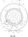
- FIG. 2B shows the orientation of the peristaltic pump assembly 14 in such a position.
- the tube 41 continues to be sequentially flattened segment by segment 102, 102', 102", opposite the tire footprint by compressive force 104 as shown at numeral 106.
- Air is pumped in the clockwise direction 94 to the inlet device 44 where it is evacuated or exhausted from the inlet device. This is not possible for the second device 200 due to the duckbill valves. Passage of exhaust air 96 from the inlet device 44 is through the filter 80 which acts to self-clean the filter of accumulated debris or particles within the porous medium.
- the outlet device With the evacuation of pumped air out of the inlet device 44, the outlet device is in the closed position and air does not flow there from to the tire cavity.
- the tire rotates further in counterclockwise direction 88 until the inlet device 44 passes the tire footprint 100 (as shown in FIG. 4A ), the airflow resumes to the outlet device 46 causing the pumped air to flow out (86) to the
- the peristaltic pump assembly 14 is positioned in the tire sidewall, radially outward of the rim flange surface 26 in the chafer 120. So positioned, the air tube 42 is radially inward from the tire footprint 100 and is thus positioned to be flattened by forces directed from the tire footprint as described above. The segment that is opposite the footprint 100 will flatten from the compressive force 114 from the footprint 100 pressing the tube segment against the rim flange surface 26.
- the positioning of the tube 42 is specifically shown as between a chafer 120 of the tire at the bead region 34 and the rim surface 26, it is not limited to same, and may be located at any region of the tire such as anywhere in the sidewall or tread.
- the subject invention provides a bidirectionally peristaltic pump for a self-inflating tire in which an air passageway 41, 42 flattens segment by segment and closes in the tire footprint 100.
- the inlet control valve 44, 200 may include a filter 80 and be self-cleaning.
- the peristaltic pump assembly 14 pumps air under rotation of the tire in either direction, one half of a revolution pumping air to the tire cavity 40 and the other half of a revolution pumping air back out of the inlet device 44 (filter 80).
- the peristaltic pump assembly 14 may be used with a secondary tire pressure monitoring system (TPMS) (not shown) of conventional configuration that serves as a system fault detector.
- the TPMS may be used to detect any fault in the self-inflation system of the tire assembly and alert the user of such a condition.
Description
- The invention relates generally to self-inflating tires and, more specifically, to a pump mechanism for such tires as well as to valve devices for such tires.
- Normal air diffusion reduces tire pressure over time. The natural state of tires is under inflated. Accordingly, drivers must repeatedly act to maintain tire pressures or they will see reduced fuel economy, tire life and reduced vehicle braking and handling performance. Tire Pressure Monitoring Systems have been proposed to warn drivers when tire pressure is significantly low. Such systems, however, remain dependant upon the driver taking remedial action when warned to re-inflate a tire to recommended pressure. It is a desirable, therefore, to incorporate a self-inflating feature within a tire that will self-inflate the tire in order to compensate for any reduction in tire pressure over time without the need for driver intervention.
-
EP-A- 2 565 059 andEP-A- 2 565 060 , which are both published only after the priority date of this application, show a self-inflating tire assembly wherein the tire has an air passageway having an inlet end and an outlet end and a valve device connected to an end of the air passageway. The valve device includes an insert and a valve body, the valve body having an interior chamber in fluid communication with the air passageway. - The invention relates to a self-inflating tire assembly in accordance with claim 1, and to a valve device in accordance with
claim 11 or 12. - Dependent claims refer to preferred embodiments of the invention.
- In a preferred aspect of the invention, a self-inflating tire assembly is disclosed. It comprises a tire having a tire cavity and a first and second sidewall extending respectively from first and second tire bead regions to a tire tread region. The tire has an air passageway, the air passageway having an inlet end and an outlet end and being operative to allow a portion of the air passageway near a tire footprint to substantially close the passageway. The outlet end of the air passageway is in fluid communication with the tire cavity. An inlet device is connected to an inlet end of the air passageway, the inlet device including a valve body mounted in the tire, wherein the valve body has an interior chamber in fluid communication with the tire cavity, said interior cavity having a first hole in fluid communication with the inlet end of the air passageway, and a channel in fluid communication with the ambient air; wherein a pressure membrane is received within the interior chamber of the valve body, and positioned to open and close the channel and being in fluid communication with the tire cavity and the interior chamber of the valve body; and wherein a spring is received within the interior chamber and is positioned to exert force upon the pressure membrane.
- In one preferred aspect of the invention, the channel is connected to a filter assembly.
- In another preferred aspect of the invention, the valve body is mounted in an insert.
- In another preferred aspect of the invention, the insert has a threaded outer wall.
- The insert has an alignment slot and the valve body has an alignment key.
- In another preferred aspect of the invention, the valve body is received in an insert that has a threaded outer surface, wherein the insert is received in a threaded receptacle formed in the tire.
- In another preferred aspect of the invention, the outlet passageway and the inlet passageway are mounted to the annular air tube substantially 180 degrees apart.
- In another preferred aspect of the invention, a self-inflating tire assembly is disclosed. It comprises a tire having a tire cavity and a first and second sidewall extending respectively from first and second tire bead regions to a tire tread region. The tire has an air passageway, the air passageway having an inlet end and an outlet end and being operative to allow a portion of the air passageway near a tire footprint to substantially close the passageway, wherein the outlet end of the air passageway is in fluid communication with the tire cavity. A valve device is connected to an end of the air passageway, the valve device including an insert mounted in the tire, wherein a valve body is mounted within the valve insert; and wherein the valve body has an interior chamber, said interior chamber having a first hole in fluid communication with the end of the air passageway, and a channel in fluid communication with the ambient air.
- In a preferred aspect of the invention, the insert is cured in the tire.
- In another preferred aspect of the invention, the insert is cured in a raised hump formed in the interior surface of the tire.
- The insert has an alignment slot and the valve body has an alignment key.
- In another preferred aspect of the invention, a check valve is positioned in the interior chamber to prevent back flow of fluid from the air passageway into the chamber.
- In another preferred aspect of the invention, a pressure membrane is received within the interior chamber of the valve body, and positioned to open and close the channel and being in fluid communication with the tire cavity and the interior chamber of the valve body.
- In another preferred aspect of the invention, the chamber has a second hole in fluid communication with the end of a second air passageway.
- In another preferred aspect of the invention, a spring is received within the interior chamber and is positioned to exert force upon the pressure membrane to bias the pressure membrane position relative to the channel in the open position.
- In another preferred aspect of the invention, a control plate is positioned between the pressure membrane and the check valve, wherein the control plate has a hole aligned for communicating flow from the chamber into the inlet end of the check valve.
- In another preferred aspect of the invention, the pressure membrane has a plug and the spring has a first end mounted about the plug, wherein the plug is positioned to close the end of the channel.
- In another preferred aspect of the invention, a self-inflating tire assembly is disclosed. It comprises a tire having a tire cavity, and a first and second sidewall extending respectively from first and second tire bead regions to a tire tread region. The tire has a first and second air passageway, said first and second air passageways having an inlet end and an outlet end and being operative to allow a portion of the air passageway near a tire footprint to substantially close the passageway, wherein the outlet ends of the first and second air passageways are in fluid communication with the tire cavity. A valve device is connected to the inlet ends of the first and second air passageway, the valve device including an insert mounted in the tire, wherein a valve body is mounted within the valve insert; wherein the valve body has a first, second and third chamber, said first chamber having a first hole in fluid communication with the inlet end of the first air passageway, said second chamber having a second hole in fluid communication with the inlet end of the second air passageway and a third chamber in fluid communication with the ambient air; wherein a first and second check valve is positioned in the first and second chamber to prevent back flow of fluid from the respective first and second air passageway into the respective first and second chamber; and wherein a pressure membrane is received within the valve body, and positioned to open and close the third chamber.
- In a preferred aspect of the invention, the pressure membrane is in fluid communication with the tire cavity and the third chamber of the valve body.
- In another preferred aspect of the invention, a spring is received within the third chamber and is positioned to exert force upon the pressure membrane to bias the pressure membrane position relative to the channel in the open position.
- In another preferred aspect of the invention, the pressure membrane has a plug and the spring has a first end mounted about the plug, wherein the plug is positioned to close the end of the channel.
- In another preferred aspect of the invention, a control plate is positioned between the pressure membrane and the check valve, wherein the control plate has a hole aligned for communicating flow from the third chamber into the first chamber.
- In another preferred aspect of the invention, a control plate is positioned between the pressure membrane and the check valve, wherein the control plate has a hole aligned for communicating flow from the third chamber into the second chamber.
- In another preferred aspect of the invention, the check valve is a duck bill type.
- In yet a further aspect of the invention, a valve device for a tire is disclosed. The valve device comprises an insert mounted in the tire or for mounting in the tire, a valve body mounted within the valve insert; wherein the valve body has a first, second and third chamber, wherein a first and second check valve is positioned in the first and second chamber; wherein a pressure membrane is received within the valve body, and positioned to open and close the third chamber; wherein said pressure membrane is in fluid communication with the tire cavity when the valve device is used with a tire and with the third chamber of the valve body; and wherein a spring is received within the third chamber and is positioned to exert force upon the pressure membrane to bias the pressure membrane position relative to the channel in the open position.
- In a preferred aspect of the invention, the valve device has a plug and the spring has a first end mounted about the plug, wherein the plug is positioned to close the end of the channel.
- In another preferred aspect of the invention, a control plate is positioned between the pressure membrane and the check valve, wherein the control plate has a hole aligned for communicating flow from the third chamber into the first chamber.
- In another preferred aspect of the invention, the control plate has a hole aligned for communicating flow from the third chamber into the second chamber.
- In another preferred aspect of the invention, the check valve is a duck bill type.
- In another preferred aspect of the invention, the insert is cured in the tire sidewall.
- In yet a further aspect of the invention, a valve device for a tire is disclosed. The valve device comprises an insert mounted in the tire or for mounting in a tire, a valve body mounted within the valve insert; wherein the valve body has a single chamber, wherein a pressure membrane is received within chamber of the valve body, and positioned to open and close a channel in fluid communication with the outside air; said pressure membrane being in fluid communication with the tire when the valve device is used with the tire; and wherein a spring is received within the chamber and is positioned to exert force upon the pressure membrane to bias the pressure membrane position relative to the channel in the open position.
- "Axial" and "axially" means lines or directions that are parallel to the axis of rotation of the tire.
- "Chafer" is a narrow strip of material placed around the outside of a tire bead to protect the cord plies from wearing and cutting against the rim and distribute the flexing above the rim.
- "Circumferential" means lines or directions extending along the perimeter of the surface of the annular tread perpendicular to the axial direction.
- "Equatorial Centerplane (CP)" means the plane perpendicular to the tire's axis of rotation and passing through the center of the tread.
- "Footprint" means the contact patch or area of contact of the tire tread with a flat surface at zero speed and under normal load and pressure.
- "Passageway" means an integrally formed pathway in the tire or a discrete tube inserted in the tire forming the pump.
- "Peristaltic" means operating by means of wave-like contractions that propel contained matter, such as air, along tubular pathways.
- "Pset" is the tire pressure value at which the control valve opens and allows air into the pump to initiate pumping action.
- "Radial" and "radially" means directions radially toward or away from the axis of rotation of the tire.
- The invention will be described by way of example and with reference to the accompanying drawings in which:
-
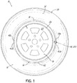
FIG. 1 is an isometric view of tire and rim assembly showing two peristaltic pump assemblies. -
FIGS. 2A and2B illustrate side views of the tire, rim, tubing, and valves showing operation of the pump to the tire cavity when the tire rotates. -
FIG. 3 is an enlarged view of pump tube location next to rim. -
FIG. 4 is an enlarged view illustrating the tube being compressed in the tire bead area. -
FIG. 5 is an enlarged cross sectional view of the tire and rim assembly with the inlet control valve and filter assembly shown mounted in the tire. -
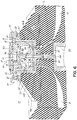
FIG. 6 is an enlarged cross sectional front view of the inlet control valve and filter assembly shown mounted in the tire. -
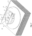
FIG. 7 is a top view of the inlet control valve shown with mounted in a partial section of the tire. -
FIG. 8 is a perspective view of the inlet control valve and filter assembly ofFigure 7 ; -
FIG. 9 is a perspective view of the control valve body; -
FIG. 10 is a bottom perspective view of the control valve body ofFIG. 9 ; -
FIG. 11 is a cross-sectional view of the control valve body ofFIG. 9 ; -
FIG. 12 is a cross-sectional side view of a second embodiment of an inlet control valve and filter assembly; -
FIG. 13 is a cross-sectional view of only the inlet control valve body ofFIG. 12 ; -
FIG. 14 is a view inside the tire of the mounting receptacles built in the tire sidewall area; and -
FIG. 15 is a schematic illustrating the pump connection. - Referring to
FIG. 1 and3 , atire assembly 10 includes atire 12 and aperistaltic pump assembly 14. Thetire 12 may be mounted on atire rim 16. The tire preferably mounts in a conventional fashion to a pair ofrim mounting surfaces 18 located adjacentouter rim flanges 22. Theouter rim flanges 22 have anouter rim surface 26. An annular rim body joins therim flanges 22 and supports the tire assembly as shown. The tire is preferably of conventional construction, having a pair ofsidewalls 32 extending fromopposite bead areas 34 to a crown ortire tread region 38. The tire and rim enclose atire cavity 40. - As shown in
FIG. 1 theperistaltic pump assembly 14 may include a first andsecond pump passageway pump passageway - The first and second pump passageway may also be integrally formed into the sidewall of the tire during vulcanization, eliminating the need for a discrete inserted tube. Each pump passageway is preferably formed by building into a selected tire component such as a chafer, a removable strip made of wire or silicone having the desired cross-sectional shape and size, which is them removed post cure to form a molded in pump tube or air passageway in the selected tire component.
- Hereinafter, the
term pump passageways FIGS. 2a and2b are illustrations of the pump passageways in the tire, and are not shown in phantom as they should be, in order to facilitate understanding of the system. The location selected for the passageway within the tire may be within a tire component residing within a high flex region of the tire, sufficient to progressively collapse the peristaltic internal hollow air passageway as the tire rotates under load thereby conveying air along the air passageway from the inlet to the pump outlet. - Each
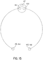
pump passageway first end inlet device 44 and asecond end inlet control valve 44 and the outlet second ends 41b, 42b are spaced apart approximately 180 degrees at respective locations forming two 180 degree pumps 41, 42. The inlet and outlet ends may be located adjacent each other, thus forming a single 360 degree pump. Other variations may be utilized, such as 90 degrees, 120 degrees, 270 degrees, etc. - Each
pump outlet end check valve 46a, b to prevent back flow of air into the pump. Thecheck valves 46a, b preferably have a threaded end which are mounted in a hump raisedsurface 64 built into the tire wall. The hump has a hole having a thread for receiving the threaded ends of the check valve, like a screw fastener. The outlet ends 41b, 42b are in fluid communication with the tire cavity so that the pumped air enters the cavity. Thecheck valve 46a,b prevents flow from the cavity from entering the pump tubes. - A first embodiment of an
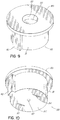
inlet control device 44 is shown inFigures 5-11 . The inlet device functions to regulate the inlet flow of bothpumps inlet control device 44 includes anouter insert 60 that is inserted into areceptacle 64 formed in the tire. Thereceptacle 64 is a raised hump formed on the tire inner surface and may optionally include a threaded inner hole that is built into the tire sidewall using a series of concentric rings of green rubber or green rubber pyramid. Alternatively, theouter insert 60 may be inserted into the receptacle center constructed by one or more concentric layers of green rubber (or elastomeric material) or green rubber pyramid (or elastomeric material) and chemically bonded to the tire during vulcanization. The insert may comprise green rubber, elastomer, nylon, brass or metal or ultra high molecular weight polyethylene (UHMWPE), or other materials known to those skilled in the art. The insert is preferably coated with a suitable adhesive such as resorcinol formaldehyde latex (RFL) or commonly referred to as "dip" known to those skilled in the art. The outer surface of the insert may be roughened and coated with the selected RFL. The outer surface of the insert may further include ridges, flanges, extensions, threads or other mechanical means in addition to the selected RFL to retain the insert into the rubber of the tire sidewall. - As shown in
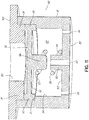
Figure 6 , theouter insert 60 has an interior section formed by an open end facing the tire cavity, abottom wall 62 opposite the open end and acurved sidewall 63. The bottom wall has amale portion 65 extending from the bottom wall. The male portion has ahole 66 there through for communicating filtered air to the interior of the valve. The bottom portion also has two opposedholes 68, 69, for alignment and fluid communication with thepump passageways gasket 70 is positioned on thebottom wall 62 of theinsert 60. The gasket is circular and flat, with three holes aligned with the threeholes valve insert 80 as shown inFigures 9-11 . Theouter body 81 of the valve insert is generally cylindrically shaped, with analignment key 82 projecting from the body. The alignment key is seated in mating engagement with an alignment slot (not shown) formed in thewall 63 of theouter insert 60. Theyalignment key 82 ensures that holes 83, 84 on thebottom surface 85 of the valve body aligns withholes 68, 69 of the insert. Theholes interior chamber 88 so that thepump outlet passageways interior chamber 88 ofvalve body 80 via the insert holes 68, 69. - As shown in
Figure 6 , apressure membrane 90 is received within the valve bodyinner chamber 88 wherein the outerflanged rim 92 of thepressure membrane 90 is seated on anannular shelf 91 formed about theinterior chamber wall 94. Thepressure membrane 90 is preferably disk shaped and formed of a flexible material such as, but not limited to, rubber, elastomer, plastic or silicone. On thevalve side 93 of the pressure membrane, aplug 96 protrudes from the membrane. The plug is positioned to plug ahole 107 ofchannel 103 to prevent flow from the outside air into thechamber 88, and hence, airflow into thepump - A
spring 98 has afirst end 99 wrapped around theplug 96, and asecond end 101 wrapped around thechannel 103 which extends from thebottom wall 105 of the chamber. Thechannel 103 has ahole 107 therethrough that is in alignment with thehole 66 ofmale portion 65.Holes filter assembly 130. Thefilter assembly 130 is mounted on the outside portion of the tire, opposite the inlet control device. The filter assembly has filter media for filtering the outside air and preventing debris and fluid from entering the pump. The filter assembly may be formed of a hard plastic cup shaped device mounted in the tire sidewall, and have an opening in fluid communication with theinternal chamber 88 of the valve body. - As shown in
Figures 9 and11 ,lid 109 is positioned over thepressure membrane 90. The lid has aflanged portion 111 which engages the rim of the pressure membrane. Thelid 109 further includes acentral hole 113. As shown inFIG. 8 , thelid 109 is secured to theinlet control device 44 via aslideable retainer 115. Theretainer 115 has opposed U shaped ends 117 which are first aligned into opposed cutout recesses 119, and then rotated into engagement withmating grooves 121 of flanged ends 123 ofinsert 60. Theretainer 115 has ahole 125 to allow fluid communication of the pressure membrane and the tire cavity. - The
pressure membrane 90 is responsive to the pressure in the interior of thetire cavity 40 on one side of the membrane, and is responsive to the pressure in the inlet chamber on the other side of the membrane. If the tire pressure is sufficiently high, the tire pressure pushes theplug 96 of the membrane into sealing engagement with the channel, overcoming the spring force, wherein the pressure membrane seals off flow from thechannel 103 so that no airflow may enter the pump inlet ends 41a, 42a. As the tire loses air pressure to a set pressure Pset, the spring exerts sufficient force on the pressure membrane, unseating the plug from channel, opening up thechannel 107. Outside air may then enter thechannel 107 of the valve body, then through thechamber 88 and out one of theholes - A second embodiment of an
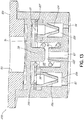
inlet device 200 is shown inFigures 12-13 . The second embodiment is the same as theinlet device 44, except for the following differences. Mounted in theinterior chamber 88 of the valve body is a first andsecond duckbill valve interior chamber 88 has been replaced with three chambers: 205, 206, 208. Filtered ambient air entersinlet chamber 205. The first and second duckbill valves are received within its ownrespective chamber flow control plate 207 has alignedholes chambers 206, 208 (depending upon the direction of tire rotation) and then through one of therespective duckbill valves duckbill valves - As will be appreciated from
FIG. 2A , two 180 degree pumps 41, 42 are shown. As the tire rotates in a direction ofrotation 88, afootprint 100 is formed against theground surface 98. Acompressive force 104 is directed into the tire from thefootprint 100 and acts to flatten asegment 110 of thepump 42 as shown atnumeral 106. Flattening of thesegment 110 of thepump 42 forces a portion of air located between the flattenedsegment 110 and the outlet check valve 46, in the direction shown byarrow 84 towards the check valve 46. As the tire continues to rotate indirection 88 along theground surface 98, thepump tube 42 will be sequentially flattened or squeezed segment bysegment direction 90 which is opposite to the direction oftire rotation 88. The sequential flattening of thepump tube 42 segment by segment causes the column of air located between the flattened segments to and the check valve 46 be pumped in thedirection 84 withinpump 42 to the outlet device 46 and into the tire cavity. - With the tire rotating in
direction 88, flattened tube segments are sequentially refilled byair 92 flowing into theinlet device pump tube 42 in thedirection 90 as shown byFIG. 2A . The inflow of air from theinlet device direction 90 continues until the outlet pump ends, rotating counterclockwise as shown with thetire rotation 88, passes thetire footprint 100. -
FIG. 2B shows the orientation of theperistaltic pump assembly 14 in such a position. In the position shown, thetube 41 continues to be sequentially flattened segment bysegment compressive force 104 as shown atnumeral 106. Air is pumped in theclockwise direction 94 to theinlet device 44 where it is evacuated or exhausted from the inlet device. This is not possible for thesecond device 200 due to the duckbill valves. Passage ofexhaust air 96 from theinlet device 44 is through thefilter 80 which acts to self-clean the filter of accumulated debris or particles within the porous medium. With the evacuation of pumped air out of theinlet device 44, the outlet device is in the closed position and air does not flow there from to the tire cavity. When the tire rotates further incounterclockwise direction 88 until theinlet device 44 passes the tire footprint 100 (as shown inFIG. 4A ), the airflow resumes to the outlet device 46 causing the pumped air to flow out (86) to thetire cavity 40. - The above-described cycle is then repeated for each tire revolution, half of each rotation resulting in pumped air going to the tire cavity and half of the rotation the pumped air is directed back out the
inlet device filter 80 to self-clean the filter. It will be appreciated that while the direction ofrotation 88 of thetire 12 is shown inFIGS. 2A and2B to be counterclockwise, the subject tire assembly and itsperistaltic pump assembly 14 will function in like manner in a (clockwise) reverse direction of rotation to that shown atnumeral 88. The peristaltic pump is accordingly bi-directional and equally functional with the tire assembly moving in a forward or a reverse direction of rotation. - The location of the peristaltic pump assembly will be understood from
FIGS. 3-4 . In one embodiment, theperistaltic pump assembly 14 is positioned in the tire sidewall, radially outward of therim flange surface 26 in thechafer 120. So positioned, theair tube 42 is radially inward from thetire footprint 100 and is thus positioned to be flattened by forces directed from the tire footprint as described above. The segment that is opposite thefootprint 100 will flatten from the compressive force 114 from thefootprint 100 pressing the tube segment against therim flange surface 26. Although the positioning of thetube 42 is specifically shown as between achafer 120 of the tire at thebead region 34 and therim surface 26, it is not limited to same, and may be located at any region of the tire such as anywhere in the sidewall or tread. - From the forgoing, it will be appreciated that the subject invention provides a bidirectionally peristaltic pump for a self-inflating tire in which an
air passageway tire footprint 100. Theinlet control valve filter 80 and be self-cleaning. Theperistaltic pump assembly 14 pumps air under rotation of the tire in either direction, one half of a revolution pumping air to thetire cavity 40 and the other half of a revolution pumping air back out of the inlet device 44 (filter 80). Theperistaltic pump assembly 14 may be used with a secondary tire pressure monitoring system (TPMS) (not shown) of conventional configuration that serves as a system fault detector. The TPMS may be used to detect any fault in the self-inflation system of the tire assembly and alert the user of such a condition.
Claims (12)
- A self-inflating tire assembly comprising a tire (12) having a tire cavity (40), a first and second sidewall (32) extending respectively from first and second tire bead regions (34) to a tire tread region; said tire (12) having an air passageway (41, 42), the air passageway (41, 42) having an inlet end (41a, 42a) and an outlet end (41b, 42b) and being operative to allow a portion of the air passageway near a tire footprint to substantially close the passageway, wherein the outlet end (41b, 42b) of the air passageway (41, 42) is in fluid communication with the tire cavity (40); and a valve device (44) connected to an end of the air passageway, the valve device (44) including an insert (60) mounted in the tire (12), wherein a valve body is mounted within the valve insert (60), wherein the valve body has an interior chamber (88), said interior chamber having a first hole (68, 69) in fluid communication with the end of the air passageway (41b, 42b), and a channel (66) in fluid communication with the ambient air; and wherein the insert (60) has an alignment slot and the valve body has an alignment key (82).
- The self inflating tire assembly of claim 1 wherein the insert (60) is cured in the tire or cured in a raised hump formed in the interior surface of the tire.
- The self inflating tire assembly of at least one of the previous claims wherein a check valve (46a, 46b) is positioned in the interior chamber (88) to prevent back flow of fluid from the air passageway (41, 42) into the chamber (88).
- The self inflating tire assembly of at least one of the previous claims wherein a pressure membrane (90) is received within the interior chamber (88) of the valve body, and positioned to open and close the channel and being in fluid communication with the tire cavity (40) and the interior chamber (88) of the valve body.
- The self inflating tire assembly of at least one of the previous claims wherein the chamber (88) has a second hole (68, 69) in fluid communication with the end of a second air passageway.
- The self inflating tire assembly of at least one of the previous claims wherein a spring (98) is received within the interior chamber (88) and is positioned to exert force upon the pressure membrane (90) to bias the pressure membrane position relative to the channel in the open position.
- The self inflating tire assembly of claim 4 wherein a control plate is positioned between the pressure membrane (90) and the check valve (46a, 46b), and wherein the control plate has a hole aligned for communicating flow from the chamber (88) into the inlet end of the check valve.
- The self inflating tire assembly of at least one of the previous claims wherein the pressure membrane (90) has a plug (96) and the spring (98) has a first end mounted about the plug, wherein the plug is positioned to close the end of the channel.
- The self-inflating tire assembly of claim 1 wherein the channel is connected to a filter assembly (130).
- The self-inflating tire assembly of claim 1 or 9 wherein the valve body is mounted in an insert, the insert optionally having a threaded outer wall or surface, and wherein the insert is received in a threaded receptacle formed in the tire.
- A valve device for a tire, the valve device (200) comprising an insert for mounting in the tire, a valve body mounted within the valve insert; wherein the valve body has a first, second and third chamber (205, 206, 208), wherein a first and second check valve (202, 204) is positioned in the first and second chamber; wherein a pressure membrane (90) is received within the valve body, and positioned to open and close the third chamber (208); said pressure membrane (90) is designed for being in fluid communication with the tire cavity (40) and the third chamber of the valve body; and wherein a spring (98) is received within the third chamber (208) and is positioned to exert force upon the pressure membrane (90) to bias the pressure membrane position relative to the channel in the open position.
- A valve device for a tire, the valve device (40) comprising an insert (60) for mounting in the tire (12), a valve body mounted within the valve insert; wherein the valve body has a single chamber (88), wherein a pressure membrane (90) is received within chamber of the valve body and positioned to open and close a channel in fluid communication with the outside air, said pressure membrane (90) being designed for being in fluid communication with the tire (12), wherein a spring (98) is received within the chamber (88) and is positioned to exert force upon the pressure membrane (90) to bias the pressure membrane position relative to the channel in the open position.
Applications Claiming Priority (2)
| Application Number | Priority Date | Filing Date | Title |
|---|---|---|---|
| US201261739843P | 2012-12-20 | 2012-12-20 | |
| US13/783,948 US9242518B2 (en) | 2012-12-20 | 2013-03-04 | Compact valve system for self-inflating tire |
Publications (2)
| Publication Number | Publication Date |
|---|---|
| EP2746072A1 EP2746072A1 (en) | 2014-06-25 |
| EP2746072B1 true EP2746072B1 (en) | 2019-03-27 |
Family
ID=49884915
Family Applications (1)
| Application Number | Title | Priority Date | Filing Date |
|---|---|---|---|
| EP13196788.7A Active EP2746072B1 (en) | 2012-12-20 | 2013-12-12 | Compact valve system for self-inflating tire |
Country Status (5)
| Country | Link |
|---|---|
| US (1) | US9242518B2 (en) |
| EP (1) | EP2746072B1 (en) |
| JP (1) | JP2014122022A (en) |
| CN (1) | CN103879244B (en) |
| BR (1) | BR102013032202A2 (en) |
Families Citing this family (15)
| Publication number | Priority date | Publication date | Assignee | Title |
|---|---|---|---|---|
| US11453258B2 (en) | 2013-03-12 | 2022-09-27 | Aperia Technologies, Inc. | System for tire inflation |
| US9340077B2 (en) * | 2013-12-09 | 2016-05-17 | The Goodyear Tire & Rubber Company | Air compressor for a pneumatic tire and a tire comprising a compressor mounted within the tire's cavity |
| US9365084B2 (en) * | 2013-12-11 | 2016-06-14 | The Goodyear Tire & Rubber Company | Self-inflating tire and pressure regulator |
| US9409454B2 (en) | 2013-12-11 | 2016-08-09 | The Goodyear Tire & Rubber Company | Self-inflating tire with hybrid pump |
| US9701166B2 (en) * | 2013-12-17 | 2017-07-11 | The Goodyear Tire & Rubber Company | Bi-directional self-inflating tire with pressure regulator |
| US9662944B2 (en) | 2013-12-23 | 2017-05-30 | The Goodyear Tire & Rubber Company | Self inflating tire with pressure regulator |
| WO2015105848A2 (en) * | 2014-01-07 | 2015-07-16 | Eaton Corporation | Self-inflating tire air regulator |
| US9327562B2 (en) * | 2014-05-05 | 2016-05-03 | The Goodyear Tire & Rubber Company | Air maintenance tire assembly |
| US9387737B2 (en) * | 2014-08-07 | 2016-07-12 | The Goodyear Tire & Rubber Company | Passage tube for air maintenance tire |
| US9783015B2 (en) | 2014-08-12 | 2017-10-10 | The Goodyear Tire & Rubber Company | Control regulator and pumping system for an air maintenance tire |
| US9744816B2 (en) | 2014-08-12 | 2017-08-29 | The Goodyear Tire & Rubber Company | Air maintenance tire |
| US10322611B2 (en) * | 2016-12-16 | 2019-06-18 | The Goodyear Tire & Rubber Company | System for an air maintenance tire assembly |
| US11285764B2 (en) | 2016-12-22 | 2022-03-29 | The Goodyear Tire & Rubber Company | Control valve for an air maintenance tire |
| US10807422B2 (en) | 2016-12-22 | 2020-10-20 | The Goodyear Tire & Rubber Company | Inlet control valve for an air maintenance tire |
| WO2020112686A1 (en) | 2018-11-27 | 2020-06-04 | Aperia Technologies, Inc. | Hub-integrated inflation system |
Family Cites Families (35)
| Publication number | Priority date | Publication date | Assignee | Title |
|---|---|---|---|---|
| US1050886A (en) * | 1910-02-23 | 1913-01-21 | Anson B Wetherell | Vehicle-tire. |
| US1250476A (en) | 1915-11-10 | 1917-12-18 | Oscar Hammersmith | Safety-valve mechanism and signal for pneumatic tires. |
| US1413531A (en) | 1921-11-03 | 1922-04-18 | K S Conrad Company | Tire alarm and gauge |
| US2095489A (en) * | 1934-09-13 | 1937-10-12 | Cotton George Albert | Pneumatic tire |
| US2634785A (en) * | 1949-05-02 | 1953-04-14 | Margaret L Tubbs | Vehicle tire |
| GB1086512A (en) * | 1964-02-24 | 1967-10-11 | Ronald Leslie Sheppard | Improvements in or relating to pneumatic tyres |
| US3247882A (en) * | 1964-05-20 | 1966-04-26 | Armstrong Rubber Co | Sidewall valve for tubeless tires |
| DE2632622A1 (en) * | 1975-07-25 | 1977-02-10 | Dunlop Ltd | TIRE |
| DE2627529A1 (en) | 1976-06-18 | 1977-12-29 | Helmut Schmidt | PRESSURE DISPLAYING DUST CAP FOR PNEUMATIC TIRES |
| US4601254A (en) | 1983-03-24 | 1986-07-22 | Huang Chung Siung | Tire pressure warning device |
| GB2255850B (en) | 1991-05-15 | 1994-11-16 | Huang Tien Tsai | Low pressure indicating device for a pneumatic tire |
| US5856619A (en) | 1997-05-13 | 1999-01-05 | Wang; Kuo-Tsai | Tire pressure indicator |
| US5957151A (en) * | 1998-01-23 | 1999-09-28 | Dalcourt; Rene | Automatic pressure regulating valve |
| US6531960B1 (en) | 1999-12-30 | 2003-03-11 | Peter Gladstone | Low tire pressure indicator |
| US6595046B2 (en) | 2000-03-10 | 2003-07-22 | Gary Lemberger | Temperature and pressure compensating indicator |
| US6525655B2 (en) | 2001-06-28 | 2003-02-25 | Tien-Tsai Huang | Diaphragm-type tire pressure indicator |
| US20040112495A1 (en) * | 2002-12-09 | 2004-06-17 | Curtis Arlen Weise | Self inflating tire |
| DE10335244A1 (en) * | 2003-08-01 | 2005-03-10 | Bayerische Motoren Werke Ag | Device for air filling a rotating pneumatic tire |
| US6911903B2 (en) | 2003-08-07 | 2005-06-28 | Tagg Technology Corp. | Tire pressure indicator |
| WO2005014307A2 (en) | 2003-08-08 | 2005-02-17 | Newport International Marketing Llc | Tire pressure indicator |
| US7131632B2 (en) | 2003-08-18 | 2006-11-07 | Kloehn Co., Ltd. | Microfluidic two-way isolation valve |
| US7667583B2 (en) | 2006-02-13 | 2010-02-23 | Measurement Ltd. | Tire pressure gauge |
| CZ303718B6 (en) * | 2006-05-23 | 2013-04-03 | Sithold S.R.O. | Retentivity component for adjusting pneumatic tyre pressure and process for producing thereof |
| US7421889B2 (en) | 2006-12-01 | 2008-09-09 | Pao-Hung Lin | Tire pressure warning assembly having a biasing member |
| US7493808B2 (en) | 2007-02-12 | 2009-02-24 | John Kostin Milanovich | Fill-through tire pressure indicator |
| US7764168B1 (en) | 2007-05-04 | 2010-07-27 | Mobiletron Electronics Co., Ltd. | Tire pressure monitoring system with a capped tire valve |
| US8042586B2 (en) * | 2009-12-21 | 2011-10-25 | The Goodyear Tire & Rubber Company | Self-inflating tire assembly |
| US8235081B2 (en) * | 2010-11-22 | 2012-08-07 | The Goodyear Tire & Rubber Company | In-line pumping assembly for self-inflating tire |
| US8656972B2 (en) * | 2011-03-23 | 2014-02-25 | The Goodyear Tire & Rubber Company | Hydraulic membrane pump assembly for air maintenance tire |
| US8573270B2 (en) | 2011-08-30 | 2013-11-05 | The Goodyear Tire & Rubber Company | Self-inflating tire and pressure regulator |
| US8701726B2 (en) * | 2011-08-30 | 2014-04-22 | The Goodyear Tire & Rubber Company | Self-inflating tire |
| US8857484B2 (en) * | 2011-08-30 | 2014-10-14 | The Goodyear Tire & Rubber Company | Self-inflating tire |
| US8991456B2 (en) * | 2012-06-28 | 2015-03-31 | The Goodyear Tire & Rubber Company | Reversible air maintenance tire and pump assembly |
| US9108476B2 (en) * | 2012-07-19 | 2015-08-18 | The Goodyear Tire & Rubber Company | Bypass air maintenance tire and pump assembly |
| US9205714B2 (en) | 2012-12-20 | 2015-12-08 | The Goodyear Tire & Rubber Company | Compact valve system for self-inflating tire |
-
2013
- 2013-03-04 US US13/783,948 patent/US9242518B2/en active Active
- 2013-12-12 EP EP13196788.7A patent/EP2746072B1/en active Active
- 2013-12-13 BR BRBR102013032202-4A patent/BR102013032202A2/en not_active Application Discontinuation
- 2013-12-16 JP JP2013259061A patent/JP2014122022A/en active Pending
- 2013-12-20 CN CN201310707388.4A patent/CN103879244B/en active Active
Non-Patent Citations (1)
| Title |
|---|
| None * |
Also Published As
| Publication number | Publication date |
|---|---|
| US9242518B2 (en) | 2016-01-26 |
| BR102013032202A2 (en) | 2014-09-02 |
| EP2746072A1 (en) | 2014-06-25 |
| US20140174620A1 (en) | 2014-06-26 |
| CN103879244B (en) | 2017-09-26 |
| JP2014122022A (en) | 2014-07-03 |
| CN103879244A (en) | 2014-06-25 |
Similar Documents
| Publication | Publication Date | Title |
|---|---|---|
| EP2746072B1 (en) | Compact valve system for self-inflating tire | |
| EP2746073B1 (en) | Compact valve system for a self-inflating tire | |
| EP2565059B1 (en) | Pneumatic tire | |
| EP2565060B1 (en) | Self-inflating tire | |
| EP2565061B1 (en) | Self-inflating tire and pressure regulator device | |
| EP2746075A2 (en) | Compact valve system for self-inflating tire | |
| EP2842772B1 (en) | Tire having a pump and valve assembly | |
| EP2343200B1 (en) | Self-inflating tire | |
| EP2886374B1 (en) | Self-inflatng tire with pressure regulator | |
| EP2842773B1 (en) | Tire having a pump and valve assembly | |
| EP2842774B1 (en) | Tire having a pump and valve assembly | |
| EP2886372B1 (en) | Self-inflating tire with inlet control valve | |
| EP2886375A2 (en) | Self inflating tire with pressure regulator | |
| EP2883718A1 (en) | Self-inflating tire with hybrid pump |
Legal Events
| Date | Code | Title | Description |
|---|---|---|---|
| PUAI | Public reference made under article 153(3) epc to a published international application that has entered the european phase |
Free format text: ORIGINAL CODE: 0009012 |
|
| 17P | Request for examination filed |
Effective date: 20131212 |
|
| AK | Designated contracting states |
Kind code of ref document: A1 Designated state(s): AL AT BE BG CH CY CZ DE DK EE ES FI FR GB GR HR HU IE IS IT LI LT LU LV MC MK MT NL NO PL PT RO RS SE SI SK SM TR |
|
| AX | Request for extension of the european patent |
Extension state: BA ME |
|
| R17P | Request for examination filed (corrected) |
Effective date: 20150105 |
|
| RBV | Designated contracting states (corrected) |
Designated state(s): AL AT BE BG CH CY CZ DE DK EE ES FI FR GB GR HR HU IE IS IT LI LT LU LV MC MK MT NL NO PL PT RO RS SE SI SK SM TR |
|
| GRAP | Despatch of communication of intention to grant a patent |
Free format text: ORIGINAL CODE: EPIDOSNIGR1 |
|
| STAA | Information on the status of an ep patent application or granted ep patent |
Free format text: STATUS: GRANT OF PATENT IS INTENDED |
|
| INTG | Intention to grant announced |
Effective date: 20181030 |
|
| GRAS | Grant fee paid |
Free format text: ORIGINAL CODE: EPIDOSNIGR3 |
|
| GRAA | (expected) grant |
Free format text: ORIGINAL CODE: 0009210 |
|
| STAA | Information on the status of an ep patent application or granted ep patent |
Free format text: STATUS: THE PATENT HAS BEEN GRANTED |
|
| AK | Designated contracting states |
Kind code of ref document: B1 Designated state(s): AL AT BE BG CH CY CZ DE DK EE ES FI FR GB GR HR HU IE IS IT LI LT LU LV MC MK MT NL NO PL PT RO RS SE SI SK SM TR |
|
| REG | Reference to a national code |
Ref country code: GB Ref legal event code: FG4D |
|
| REG | Reference to a national code |
Ref country code: CH Ref legal event code: EP |
|
| REG | Reference to a national code |
Ref country code: AT Ref legal event code: REF Ref document number: 1112611 Country of ref document: AT Kind code of ref document: T Effective date: 20190415 |
|
| REG | Reference to a national code |
Ref country code: IE Ref legal event code: FG4D |
|
| REG | Reference to a national code |
Ref country code: DE Ref legal event code: R096 Ref document number: 602013052879 Country of ref document: DE |
|
| PG25 | Lapsed in a contracting state [announced via postgrant information from national office to epo] |
Ref country code: SE Free format text: LAPSE BECAUSE OF FAILURE TO SUBMIT A TRANSLATION OF THE DESCRIPTION OR TO PAY THE FEE WITHIN THE PRESCRIBED TIME-LIMIT Effective date: 20190327 Ref country code: FI Free format text: LAPSE BECAUSE OF FAILURE TO SUBMIT A TRANSLATION OF THE DESCRIPTION OR TO PAY THE FEE WITHIN THE PRESCRIBED TIME-LIMIT Effective date: 20190327 Ref country code: NO Free format text: LAPSE BECAUSE OF FAILURE TO SUBMIT A TRANSLATION OF THE DESCRIPTION OR TO PAY THE FEE WITHIN THE PRESCRIBED TIME-LIMIT Effective date: 20190627 Ref country code: LT Free format text: LAPSE BECAUSE OF FAILURE TO SUBMIT A TRANSLATION OF THE DESCRIPTION OR TO PAY THE FEE WITHIN THE PRESCRIBED TIME-LIMIT Effective date: 20190327 |
|
| REG | Reference to a national code |
Ref country code: NL Ref legal event code: MP Effective date: 20190327 |
|
| PG25 | Lapsed in a contracting state [announced via postgrant information from national office to epo] |
Ref country code: BG Free format text: LAPSE BECAUSE OF FAILURE TO SUBMIT A TRANSLATION OF THE DESCRIPTION OR TO PAY THE FEE WITHIN THE PRESCRIBED TIME-LIMIT Effective date: 20190627 Ref country code: GR Free format text: LAPSE BECAUSE OF FAILURE TO SUBMIT A TRANSLATION OF THE DESCRIPTION OR TO PAY THE FEE WITHIN THE PRESCRIBED TIME-LIMIT Effective date: 20190628 Ref country code: HR Free format text: LAPSE BECAUSE OF FAILURE TO SUBMIT A TRANSLATION OF THE DESCRIPTION OR TO PAY THE FEE WITHIN THE PRESCRIBED TIME-LIMIT Effective date: 20190327 Ref country code: NL Free format text: LAPSE BECAUSE OF FAILURE TO SUBMIT A TRANSLATION OF THE DESCRIPTION OR TO PAY THE FEE WITHIN THE PRESCRIBED TIME-LIMIT Effective date: 20190327 Ref country code: LV Free format text: LAPSE BECAUSE OF FAILURE TO SUBMIT A TRANSLATION OF THE DESCRIPTION OR TO PAY THE FEE WITHIN THE PRESCRIBED TIME-LIMIT Effective date: 20190327 Ref country code: RS Free format text: LAPSE BECAUSE OF FAILURE TO SUBMIT A TRANSLATION OF THE DESCRIPTION OR TO PAY THE FEE WITHIN THE PRESCRIBED TIME-LIMIT Effective date: 20190327 |
|
| REG | Reference to a national code |
Ref country code: AT Ref legal event code: MK05 Ref document number: 1112611 Country of ref document: AT Kind code of ref document: T Effective date: 20190327 |
|
| PG25 | Lapsed in a contracting state [announced via postgrant information from national office to epo] |
Ref country code: RO Free format text: LAPSE BECAUSE OF FAILURE TO SUBMIT A TRANSLATION OF THE DESCRIPTION OR TO PAY THE FEE WITHIN THE PRESCRIBED TIME-LIMIT Effective date: 20190327 Ref country code: CZ Free format text: LAPSE BECAUSE OF FAILURE TO SUBMIT A TRANSLATION OF THE DESCRIPTION OR TO PAY THE FEE WITHIN THE PRESCRIBED TIME-LIMIT Effective date: 20190327 Ref country code: EE Free format text: LAPSE BECAUSE OF FAILURE TO SUBMIT A TRANSLATION OF THE DESCRIPTION OR TO PAY THE FEE WITHIN THE PRESCRIBED TIME-LIMIT Effective date: 20190327 Ref country code: ES Free format text: LAPSE BECAUSE OF FAILURE TO SUBMIT A TRANSLATION OF THE DESCRIPTION OR TO PAY THE FEE WITHIN THE PRESCRIBED TIME-LIMIT Effective date: 20190327 Ref country code: AL Free format text: LAPSE BECAUSE OF FAILURE TO SUBMIT A TRANSLATION OF THE DESCRIPTION OR TO PAY THE FEE WITHIN THE PRESCRIBED TIME-LIMIT Effective date: 20190327 Ref country code: SK Free format text: LAPSE BECAUSE OF FAILURE TO SUBMIT A TRANSLATION OF THE DESCRIPTION OR TO PAY THE FEE WITHIN THE PRESCRIBED TIME-LIMIT Effective date: 20190327 Ref country code: PT Free format text: LAPSE BECAUSE OF FAILURE TO SUBMIT A TRANSLATION OF THE DESCRIPTION OR TO PAY THE FEE WITHIN THE PRESCRIBED TIME-LIMIT Effective date: 20190727 |
|
| PG25 | Lapsed in a contracting state [announced via postgrant information from national office to epo] |
Ref country code: PL Free format text: LAPSE BECAUSE OF FAILURE TO SUBMIT A TRANSLATION OF THE DESCRIPTION OR TO PAY THE FEE WITHIN THE PRESCRIBED TIME-LIMIT Effective date: 20190327 Ref country code: SM Free format text: LAPSE BECAUSE OF FAILURE TO SUBMIT A TRANSLATION OF THE DESCRIPTION OR TO PAY THE FEE WITHIN THE PRESCRIBED TIME-LIMIT Effective date: 20190327 |
|
| PG25 | Lapsed in a contracting state [announced via postgrant information from national office to epo] |
Ref country code: AT Free format text: LAPSE BECAUSE OF FAILURE TO SUBMIT A TRANSLATION OF THE DESCRIPTION OR TO PAY THE FEE WITHIN THE PRESCRIBED TIME-LIMIT Effective date: 20190327 Ref country code: IS Free format text: LAPSE BECAUSE OF FAILURE TO SUBMIT A TRANSLATION OF THE DESCRIPTION OR TO PAY THE FEE WITHIN THE PRESCRIBED TIME-LIMIT Effective date: 20190727 |
|
| REG | Reference to a national code |
Ref country code: DE Ref legal event code: R097 Ref document number: 602013052879 Country of ref document: DE |
|
| PG25 | Lapsed in a contracting state [announced via postgrant information from national office to epo] |
Ref country code: DK Free format text: LAPSE BECAUSE OF FAILURE TO SUBMIT A TRANSLATION OF THE DESCRIPTION OR TO PAY THE FEE WITHIN THE PRESCRIBED TIME-LIMIT Effective date: 20190327 |
|
| PLBE | No opposition filed within time limit |
Free format text: ORIGINAL CODE: 0009261 |
|
| STAA | Information on the status of an ep patent application or granted ep patent |
Free format text: STATUS: NO OPPOSITION FILED WITHIN TIME LIMIT |
|
| PG25 | Lapsed in a contracting state [announced via postgrant information from national office to epo] |
Ref country code: SI Free format text: LAPSE BECAUSE OF FAILURE TO SUBMIT A TRANSLATION OF THE DESCRIPTION OR TO PAY THE FEE WITHIN THE PRESCRIBED TIME-LIMIT Effective date: 20190327 |
|
| 26N | No opposition filed |
Effective date: 20200103 |
|
| PG25 | Lapsed in a contracting state [announced via postgrant information from national office to epo] |
Ref country code: TR Free format text: LAPSE BECAUSE OF FAILURE TO SUBMIT A TRANSLATION OF THE DESCRIPTION OR TO PAY THE FEE WITHIN THE PRESCRIBED TIME-LIMIT Effective date: 20190327 |
|
| REG | Reference to a national code |
Ref country code: CH Ref legal event code: PL |
|
| REG | Reference to a national code |
Ref country code: BE Ref legal event code: MM Effective date: 20191231 |
|
| PG25 | Lapsed in a contracting state [announced via postgrant information from national office to epo] |
Ref country code: MC Free format text: LAPSE BECAUSE OF FAILURE TO SUBMIT A TRANSLATION OF THE DESCRIPTION OR TO PAY THE FEE WITHIN THE PRESCRIBED TIME-LIMIT Effective date: 20190327 |
|
| GBPC | Gb: european patent ceased through non-payment of renewal fee |
Effective date: 20191212 |
|
| PG25 | Lapsed in a contracting state [announced via postgrant information from national office to epo] |
Ref country code: LU Free format text: LAPSE BECAUSE OF NON-PAYMENT OF DUE FEES Effective date: 20191212 Ref country code: IE Free format text: LAPSE BECAUSE OF NON-PAYMENT OF DUE FEES Effective date: 20191212 Ref country code: GB Free format text: LAPSE BECAUSE OF NON-PAYMENT OF DUE FEES Effective date: 20191212 |
|
| PG25 | Lapsed in a contracting state [announced via postgrant information from national office to epo] |
Ref country code: BE Free format text: LAPSE BECAUSE OF NON-PAYMENT OF DUE FEES Effective date: 20191231 Ref country code: CH Free format text: LAPSE BECAUSE OF NON-PAYMENT OF DUE FEES Effective date: 20191231 Ref country code: LI Free format text: LAPSE BECAUSE OF NON-PAYMENT OF DUE FEES Effective date: 20191231 |
|
| PG25 | Lapsed in a contracting state [announced via postgrant information from national office to epo] |
Ref country code: CY Free format text: LAPSE BECAUSE OF FAILURE TO SUBMIT A TRANSLATION OF THE DESCRIPTION OR TO PAY THE FEE WITHIN THE PRESCRIBED TIME-LIMIT Effective date: 20190327 |
|
| PG25 | Lapsed in a contracting state [announced via postgrant information from national office to epo] |
Ref country code: MT Free format text: LAPSE BECAUSE OF FAILURE TO SUBMIT A TRANSLATION OF THE DESCRIPTION OR TO PAY THE FEE WITHIN THE PRESCRIBED TIME-LIMIT Effective date: 20190327 Ref country code: HU Free format text: LAPSE BECAUSE OF FAILURE TO SUBMIT A TRANSLATION OF THE DESCRIPTION OR TO PAY THE FEE WITHIN THE PRESCRIBED TIME-LIMIT; INVALID AB INITIO Effective date: 20131212 |
|
| PG25 | Lapsed in a contracting state [announced via postgrant information from national office to epo] |
Ref country code: MK Free format text: LAPSE BECAUSE OF FAILURE TO SUBMIT A TRANSLATION OF THE DESCRIPTION OR TO PAY THE FEE WITHIN THE PRESCRIBED TIME-LIMIT Effective date: 20190327 |
|
| PGFP | Annual fee paid to national office [announced via postgrant information from national office to epo] |
Ref country code: IT Payment date: 20231110 Year of fee payment: 11 Ref country code: FR Payment date: 20231009 Year of fee payment: 11 Ref country code: DE Payment date: 20231017 Year of fee payment: 11 |