JP2014122022A - Compact valve system for self-inflating tire - Google Patents
Compact valve system for self-inflating tire Download PDFInfo
- Publication number
- JP2014122022A JP2014122022A JP2013259061A JP2013259061A JP2014122022A JP 2014122022 A JP2014122022 A JP 2014122022A JP 2013259061 A JP2013259061 A JP 2013259061A JP 2013259061 A JP2013259061 A JP 2013259061A JP 2014122022 A JP2014122022 A JP 2014122022A
- Authority
- JP
- Japan
- Prior art keywords
- tire
- chamber
- self
- air passage
- valve
- Prior art date
- Legal status (The legal status is an assumption and is not a legal conclusion. Google has not performed a legal analysis and makes no representation as to the accuracy of the status listed.)
- Pending
Links
Images


Classifications
-
- B—PERFORMING OPERATIONS; TRANSPORTING
- B60—VEHICLES IN GENERAL
- B60C—VEHICLE TYRES; TYRE INFLATION; TYRE CHANGING; CONNECTING VALVES TO INFLATABLE ELASTIC BODIES IN GENERAL; DEVICES OR ARRANGEMENTS RELATED TO TYRES
- B60C29/00—Arrangements of tyre-inflating valves to tyres or rims; Accessories for tyre-inflating valves, not otherwise provided for
- B60C29/04—Connection to tyres or inner tubes
-
- B—PERFORMING OPERATIONS; TRANSPORTING
- B60—VEHICLES IN GENERAL
- B60C—VEHICLE TYRES; TYRE INFLATION; TYRE CHANGING; CONNECTING VALVES TO INFLATABLE ELASTIC BODIES IN GENERAL; DEVICES OR ARRANGEMENTS RELATED TO TYRES
- B60C23/00—Devices for measuring, signalling, controlling, or distributing tyre pressure or temperature, specially adapted for mounting on vehicles; Arrangement of tyre inflating devices on vehicles, e.g. of pumps or of tanks; Tyre cooling arrangements
- B60C23/10—Arrangement of tyre-inflating pumps mounted on vehicles
- B60C23/12—Arrangement of tyre-inflating pumps mounted on vehicles operated by a running wheel
- B60C23/121—Arrangement of tyre-inflating pumps mounted on vehicles operated by a running wheel the pumps being mounted on the tyres
- B60C23/123—Elongate peristaltic pumps
-
- B—PERFORMING OPERATIONS; TRANSPORTING
- B60—VEHICLES IN GENERAL
- B60C—VEHICLE TYRES; TYRE INFLATION; TYRE CHANGING; CONNECTING VALVES TO INFLATABLE ELASTIC BODIES IN GENERAL; DEVICES OR ARRANGEMENTS RELATED TO TYRES
- B60C23/00—Devices for measuring, signalling, controlling, or distributing tyre pressure or temperature, specially adapted for mounting on vehicles; Arrangement of tyre inflating devices on vehicles, e.g. of pumps or of tanks; Tyre cooling arrangements
- B60C23/10—Arrangement of tyre-inflating pumps mounted on vehicles
- B60C23/12—Arrangement of tyre-inflating pumps mounted on vehicles operated by a running wheel
- B60C23/135—Arrangement of tyre-inflating pumps mounted on vehicles operated by a running wheel activated due to tyre deformation
-
- Y—GENERAL TAGGING OF NEW TECHNOLOGICAL DEVELOPMENTS; GENERAL TAGGING OF CROSS-SECTIONAL TECHNOLOGIES SPANNING OVER SEVERAL SECTIONS OF THE IPC; TECHNICAL SUBJECTS COVERED BY FORMER USPC CROSS-REFERENCE ART COLLECTIONS [XRACs] AND DIGESTS
- Y10—TECHNICAL SUBJECTS COVERED BY FORMER USPC
- Y10T—TECHNICAL SUBJECTS COVERED BY FORMER US CLASSIFICATION
- Y10T152/00—Resilient tires and wheels
- Y10T152/10—Tires, resilient
- Y10T152/10495—Pneumatic tire or inner tube
Abstract
Description
本発明は、一般に、自動膨張タイヤに関し、より詳細には、そのようなタイヤのためのポンプ機構に関する。 The present invention relates generally to self-expanding tires and, more particularly, to a pump mechanism for such tires.
通常の空気拡散により、タイヤ空気圧は時間の経過とともに低下する。タイヤが自然な状態であるのは、膨張している状態である。したがって、運転者は、繰り返しタイヤ空気圧を維持するように行動しなければならず、さもなければ燃費が低下し、タイヤの寿命が短くなり、車両の制動/ハンドリング性能が低下することを知ることになる。タイヤ空気圧監視システム(Tire Pressure Monitoring System)が、タイヤ空気圧が著しく低い場合に運転者に警告するために提案されてきている。 Due to normal air diffusion, the tire pressure decreases with time. The tire is in its natural state when it is inflated. Therefore, the driver must repeatedly act to maintain tire pressure, otherwise knowing that fuel consumption is reduced, tire life is shortened and vehicle braking / handling performance is reduced. Become. Tire pressure monitoring systems have been proposed to alert drivers when tire pressures are significantly low.
しかし、そのようなシステムは、依然として、タイヤを推奨圧力まで再膨張させるよう警告された場合に運転者が是正措置をとることに依存したままである。したがって、運転者が介入する必要なしに経時的なタイヤ空気圧の低下を補償するために、タイヤ内部にタイヤを自動膨張させる自動膨張機能を組み込むことが望ましい。 However, such systems remain dependent on the driver taking corrective action when the tire is warned to reinflate to the recommended pressure. Therefore, it is desirable to incorporate an automatic inflation function that automatically inflates the tire inside the tire to compensate for the tire pressure drop over time without the need for driver intervention.
本発明は、第1の態様において、自動膨張タイヤアセンブリを提供する。この自動膨張式タイヤアセンブリは、タイヤ空洞部と、第1のタイヤビード領域および第2のタイヤビード領域からそれぞれタイヤトレッド領域まで延びている第1のサイドウォールおよび第2のサイドウォールと、を有するタイヤを備えている。自動膨張タイヤは、入口端部および出口端部を有し、タイヤフットプリント付近で自体の一部により実質的に閉じることが可能になるように動作可能である空気通路を有する。空気通路の出口端部は、タイヤ空洞部と流体連通している。 In a first aspect, the present invention provides a self-expanding tire assembly. The self-expanding tire assembly includes a tire cavity and first and second sidewalls extending from the first tire bead region and the second tire bead region to the tire tread region, respectively. Has tires. A self-expanding tire has an inlet end and an outlet end and has an air passage that is operable to be substantially closed by a portion of itself near the tire footprint. The outlet end of the air passage is in fluid communication with the tire cavity.
自動膨張タイヤは、空気通路の入口端部に接続されている入口デバイスをさらに含み、入口デバイスは、タイヤ内に取り付けられているバルブ本体を含み、バルブ本体は、タイヤ空洞部と流体連通しており、空気通路の入口端部と流体連通している第1の穴部を有する内室、及び周囲空気と流体連通しているチャネルを有する。圧膜が、バルブ本体の内室内に設けられており、チャネルを開閉するように配置され、タイヤ空洞部およびバルブ本体の内室と流体連通しており、ばねが、内室内に設けられており、圧膜に力を加えるように配置されている。 The self-expanding tire further includes an inlet device connected to the inlet end of the air passage, the inlet device including a valve body mounted in the tire, the valve body in fluid communication with the tire cavity. And an inner chamber having a first bore in fluid communication with the inlet end of the air passage and a channel in fluid communication with ambient air. A pressure membrane is provided in the inner chamber of the valve body, is arranged to open and close the channel, is in fluid communication with the tire cavity and the inner chamber of the valve body, and a spring is provided in the inner chamber. , Arranged to apply force to the pressure membrane.
本発明は、第2の態様において、自動膨張タイヤアセンブリを提供する。自動膨張タイヤアセンブリは、タイヤとバルブデバイスを備えている。タイヤは、タイヤ空洞部と、第1のタイヤビード領域および第2のタイヤビード領域からそれぞれタイヤトレッド領域まで延びている第1のサイドウォールおよび第2のサイドウォールと、を有する。タイヤは、入口端部と出口端部とを有し、タイヤフットプリント付近で自体の一部により実質的に閉じることが可能になるように動作可能である空気通路を有する。空気通路の出口端部は、タイヤ空洞部と流体連通している。バルブデバイスは、タイヤ内に取り付けられているインサートと、空気通路の端部と流体連通している第1の穴部を有する内室、および周囲空気と流体連通しているチャネルを有し、バルブインサートの内部に取り付けられているバルブ本体と、を有し、空気通路の端部に接続されている。 In a second aspect, the present invention provides a self-expanding tire assembly. The self-expanding tire assembly includes a tire and a valve device. The tire includes a tire cavity, and a first sidewall and a second sidewall extending from the first tire bead region and the second tire bead region to the tire tread region, respectively. The tire has an air passage that has an inlet end and an outlet end and is operable to be substantially closed by a portion of itself near the tire footprint. The outlet end of the air passage is in fluid communication with the tire cavity. A valve device has an insert mounted in a tire, an inner chamber having a first hole in fluid communication with an end of an air passage, and a channel in fluid communication with ambient air, A valve body attached to the interior of the insert and connected to the end of the air passage.
本発明は、第3の態様において、自動膨張タイヤアセンブリを提供する。自動膨張式タイヤアセンブリは、タイヤとバルブデバイスとを備えている。タイヤは、タイヤ空洞部と、第1のタイヤビード領域および第2のタイヤビード領域からそれぞれタイヤトレッド領域まで延びている第1のサイドウォールおよび第2のサイドウォールとを有する。タイヤは、入口端部および出口端部を有し、タイヤフットプリント付近で自体の一部が実質的に閉鎖することを可能にするように動作可能である第1の空気通路および第2の空気通路を有する。第1の空気通路および第2の空気通路の出口端部は、タイヤ空洞部と流体連通している。バルブデバイスは、タイヤ内に取り付けられているインサートと、第1の室、第2の室、および第3の室を有し、インサートの内部に取り付けられているバルブ本体と、を有し、第1の空気通路および第2の空気通路の入口端部に接続されている。第1の室は、第1の空気通路の入口端部と流体連通している第1の穴部を有し、第2の室は、第2の空気通路の入口端部と流体連通している第2の穴部を有し、第3の室は周囲空気と流体連通している。第1のチェックバルブおよび第2のチェックバルブが、第1の空気通路および第2の空気通路からの流体の逆流がそれぞれ第1の室および第2の室内に入るのを防止するように、第1の室および第2の室内に配置されている。圧膜は、バルブ本体の内部に設けられ、第3の室を開閉するように配置されている。 In a third aspect, the present invention provides a self-expanding tire assembly. The self-inflating tire assembly includes a tire and a valve device. The tire includes a tire cavity, and a first sidewall and a second sidewall extending from the first tire bead region and the second tire bead region to the tire tread region, respectively. The tire has a first air passage and a second air having an inlet end and an outlet end and operable to allow a portion of the tire to substantially close near the tire footprint. Has a passage. The outlet ends of the first air passage and the second air passage are in fluid communication with the tire cavity. The valve device has an insert mounted in the tire, a valve body having a first chamber, a second chamber, and a third chamber and mounted inside the insert, Connected to the inlet ends of one air passage and the second air passage. The first chamber has a first hole in fluid communication with the inlet end of the first air passage, and the second chamber is in fluid communication with the inlet end of the second air passage. The third chamber is in fluid communication with ambient air. The first check valve and the second check valve are configured to prevent back flow of fluid from the first air passage and the second air passage from entering the first chamber and the second chamber, respectively. Arranged in one chamber and the second chamber. The pressure film is provided inside the valve body and is arranged to open and close the third chamber.
本発明は、第4の態様において、タイヤのためのバルブデバイスを提供する。バルブデバイスは、タイヤ内に取り付けられているインサートと、第1の室と、第2の室と、第3の室とを有し、インサートの内部に取り付けられているバルブ本体と、を備えている。第1のチェックバルブおよび第2のチェックバルブが、それぞれ第1の室および第2の室内に配置されている。圧膜が、バルブ本体の内部に設けられ、第3の室を開閉するように配置されており、タイヤ空洞部およびバルブ本体の第3の室と流体連通している。ばねが、第3の室の内部に設けられており、圧膜に力を加えて、開いた状態にあるチャネルに対する圧膜位置を付勢するように配置されている。 In a fourth aspect, the present invention provides a valve device for a tire. The valve device includes an insert attached in a tire, a first chamber, a second chamber, and a third chamber, and a valve body attached to the inside of the insert. Yes. A first check valve and a second check valve are disposed in the first chamber and the second chamber, respectively. A pressure membrane is provided inside the valve body, is disposed to open and close the third chamber, and is in fluid communication with the tire cavity and the third chamber of the valve body. A spring is provided within the third chamber and is arranged to apply a force to the pressure film to bias the pressure film position relative to the open channel.
本発明は、第5の態様において、タイヤのためのバルブデバイスを提供する。バルブデバイスは、タイヤ内に取り付けられているインサートと、単一の室を有し、インサートの内部に取り付けられているバルブ本体と、を備えている。圧膜が、バルブ本体の室の内部に設けられており、外気と流体連通しているチャネルを開閉するように配置されており、タイヤと流体連通している。ばねが、室の内部に設けられており、圧膜に力を加えて、開いた状態にあるチャネルに対する圧膜位置を付勢するように配置されている。 In a fifth aspect, the present invention provides a valve device for a tire. The valve device includes an insert mounted in the tire and a valve body having a single chamber and mounted inside the insert. A pressure membrane is provided inside the chamber of the valve body, is arranged to open and close a channel in fluid communication with the outside air, and is in fluid communication with the tire. A spring is provided inside the chamber and is arranged to apply a force to the pressure film to bias the pressure film position relative to the open channel.
[定義]
タイヤの「アスペクト比」は、パーセンテージとして表現するために100を乗じた、タイヤの断面幅(SW)に対するタイヤの断面高さ(SH)の比を意味する。
[Definition]
“Aspect ratio” of a tire means the ratio of the tire's cross-sectional height (SH) to the tire's cross-sectional width (SW), multiplied by 100 to express as a percentage.
「非対称トレッド」は、タイヤの中心面、すなわち赤道面(EP)に関して対称でないトレッドパターンを有するトレッドを意味する。 “Asymmetric tread” means a tread having a tread pattern that is not symmetrical with respect to the center plane of the tire, ie the equatorial plane (EP).
「軸方向の」および「軸方向に」は、タイヤの回転軸に平行な線または方向を意味する。 “Axial” and “in the axial direction” mean a line or direction parallel to the axis of rotation of the tire.
「チェーファ」は、リムに対する摩耗及び切断からコードプライを保護し、リムの上方に曲げを分散するために、タイヤビードの外側を取り巻いて配置されている細い材料ストリップである。 A “chafer” is a thin strip of material that is placed around the outside of the tire bead to protect the cord ply from abrasion and cutting against the rim and to distribute the bend above the rim.
「周方向の」は、軸方向に対して垂直な、環状トレッドの表面の外周に沿って延びる線または方向を意味する。 “Circumferential” means a line or direction extending along the outer periphery of the surface of the annular tread perpendicular to the axial direction.
「赤道中心面(CP)」は、タイヤの回転軸に対して垂直であり、かつトレッドの中心を通過する平面を意味する。 “Equatorial center plane (CP)” means a plane perpendicular to the tire's axis of rotation and passing through the center of the tread.
「フットプリント」は、ゼロ速度でのかつ通常負荷および常圧下での平面とのタイヤトレッドの接触部分すなわち領域を意味する。 “Footprint” means the portion or area of contact of a tire tread with a plane at zero speed and under normal load and normal pressure.
「車内側」は、タイヤがホイールに取り付けられた場合および該ホイールが車両に取り付けられた場合に、タイヤの、車両に最も近い側を意味する。 “Vehicle interior” means the side of the tire closest to the vehicle when the tire is attached to the wheel and when the wheel is attached to the vehicle.
「横方向」は、軸方向を意味する。 “Lateral direction” means an axial direction.
「横方向縁部」は、通常負荷および通常タイヤ空気圧下で測定される軸方向最外のトレッド接触部分つまりフットプリントに接する線を意味し、該線は赤道中心面に平行である。 “Lateral edge” means the line that touches the axially outermost tread contact or footprint, measured under normal load and normal tire pressure, which is parallel to the equator center plane.
「正味接触面積」は、両外側縁間にあるトレッド全体の総面積で割られた、トレッドの円周全体を巡る両外側縁間にあるトレッド要素に接触している地面の総面積を意味する。 “Net contact area” means the total area of the ground in contact with the tread elements between the outer edges around the entire tread circumference divided by the total area of the entire tread between the outer edges. .
「無方向性トレッド」は、好適な前進方向を有さず、かつトレッドのパターンが好適な移動方向と確実に一致するように車両上の特定のホイール位置または複数のホイール位置に配置される必要がないトレッドを意味する。逆に、方向性トレッドパターンが、好適な移動方向を有し、特定のホイール配置を必要とする。 “Non-directional treads” do not have a preferred forward direction and must be placed at a specific wheel position or multiple wheel positions on the vehicle to ensure that the tread pattern matches the preferred direction of travel Means no tread. Conversely, a directional tread pattern has a suitable direction of movement and requires a specific wheel arrangement.
「車外側」は、タイヤがホイールに取り付けられた場合および該ホイールが車両に取り付けられた場合に、タイヤの、車両から最も遠く離れた側を意味する。 “Outside the vehicle” means the side of the tire farthest away from the vehicle when the tire is attached to the wheel and when the wheel is attached to the vehicle.
「通路」は、タイヤ内に一体的に形成された経路、またはポンプを形成している、タイヤ内に挿入された別個のチューブを意味する。 “Passage” means a path integrally formed within the tire or a separate tube inserted into the tire forming a pump.
「蠕動の」は、チューブ状通路に沿って、空気など、含まれた物質を進ませる波様収縮による動作を意味する。 “Peristaltic” means an action by wave-like contraction that advances contained substances such as air along a tubular passage.
「Pset」は、コントロールバルブが開き、空気がポンプ内に入ってポンプ作用を開始することが可能になる、タイヤ空気圧値を意味する。 “Pset” means the tire pressure value at which the control valve opens, allowing air to enter the pump and begin pumping.
「径方向の」および「径方向に」は、半径方向でタイヤの回転軸に向かう、またはタイヤの回転軸から離れる方向を意味する。 “Radial” and “radially” refer to the direction radially toward or away from the tire's axis of rotation.
「リブ」は、少なくとも1つの周方向溝部と第2のそのような溝部または横方向縁のどちらかとにより画定されている、トレッド上の周方向に延びているゴムストリップを意味し、該ストリップは、最大限の深さの溝部により横方向に分割されていない。 “Rib” means a circumferentially extending rubber strip on a tread defined by at least one circumferential groove and either a second such groove or a lateral edge, the strip being It is not divided laterally by the groove part of maximum depth.
「サイプ」は、トレッド面を細分しかつトラクションを向上させる、タイヤのトレッド要素内に成形されている小スロットを意味し、サイプは、概して、幅が狭く、タイヤのフットプリントにおいて開いたままである溝部とは反対に、タイヤのフットプリントにおいて閉じている。 “Sipe” means a small slot molded into the tread element of a tire that subdivides the tread surface and improves traction, and the sipe is generally narrow and remains open in the tire footprint Contrary to the groove, it is closed in the tire footprint.
「トレッド要素」または「トラクション要素」は、隣接する溝部の形状を有することにより画定されているリブまたはブロック要素を意味する。 “Tread element” or “traction element” means a rib or block element defined by having the shape of an adjacent groove.
「トレッド弧幅」は、トレッドの両横方向縁の間で測定される、トレッドの円弧長を意味する。 “Tread arc width” means the arc length of the tread measured between the lateral edges of the tread.
本発明は、一例として、添付図面を参照して説明する。 The present invention will now be described by way of example with reference to the accompanying drawings.
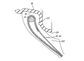
図1および3を参照すると、タイヤアセンブリ10が、タイヤ12と、蠕動ポンプアセンブリ14と、タイヤリム16とを含む。タイヤは、従来の様式では、外側リムフランジ22に隣接して配置されている一対のリム取付け面18に取り付けられている。リムフランジ22は外側リム面26を有する。環状リム本体が両リムフランジ22を接続しており、図示のようにタイヤアセンブリ10を支持している。タイヤは、対向する両ビード領域34からクラウンまたはタイヤトレッド領域38まで延びている一対のサイドウォール32を有する、従来の構造である。タイヤおよびリムはタイヤ空洞部40を囲んでいる。
With reference to FIGS. 1 and 3, a
図1に示されている通り、蠕動ポンプアセンブリ14は、タイヤ12内に、好ましくはビード領域34に近いタイヤ12のサイドウォール領域に配置されている第1のポンプ通路41と第2のポンプ通路42とを含んでいてもよい。各ポンプ通路41、42は、プラスチック、エラストマーまたはゴム化合物などの弾性可撓性材料から形成されている別個のチューブで形成されていてもよく、外力の影響下でチューブが平らな状態になり、そのような力の除去時に断面が概ね円形の元の状態に戻る場合に繰り返される変形サイクルに耐えることができる。チューブは、本明細書に記載されている目的のために十分な体積の空気を動作可能に送り、かつ以下で記載されるようにタイヤアセンブリの内部の動作可能な位置にチューブを配置することを可能にするのに十分なサイズである。チューブは、楕円断面形状を有することが好ましいが、円形または卵形などの他の形状が利用されてもよい。
As shown in FIG. 1, the
また、第1のポンプ通路および第2のポンプ通路は、加硫中にタイヤ12のサイドウォール32に一体的に形成されて、個別の挿入されたチューブの必要が無くなる場合もある。各ポンプ通路は、所望の断面形状およびサイズを有するワイヤまたはシリコーンで作製されている除去可能なストリップであり、次いで硬化後に除去されて、選択されたタイヤ構成要素のポンプチューブまたは空気通路内に成形物を形成する、チェーファなどの選択されたタイヤ構成要素に構築することにより形成されることが好ましい。
Also, the first pump passage and the second pump passage may be formed integrally with the
以後、「ポンプ通路41、42」という用語は、取り付けられたチューブまたは一体的に成形された通路のどちらかを指す。図2Aおよび図2Bは、タイヤ内のポンプ通路の図であり、システムを理解し易くするために、そうであるべき透視状態で示されていない。タイヤの内部の通路のために選択された位置は、タイヤが荷重下で回転するにつれて、蠕動内部中空空気通路を徐々に潰すのに十分な、タイヤの高屈曲性領域内にあるタイヤ構成要素の内部であってよく、それにより入口からポンプ出口まで空気通路に沿って空気が運ばれる。
Hereinafter, the term “
各ポンプ通路41、42が、入口デバイス44により結合されている第1の端部41a、42aと第2の端部41b、42bとを有する。図示の通り、入口コントロールバルブ44と第2の出口端部41b、42bとは各位置で約180度離間されており、2つの180度ポンプ41、42を形成している。入口端部および出口端部は、互いに隣接して配置されていて、したがって単一の360度ポンプを形成していてもよい。90度、120度、270度等の他の変形形態が利用されていてもよい。
Each
各ポンプ出口端部41b、42bは、空気のポンプ内への逆流を防止するチェックバルブ46a、46bを有することが好ましい。チェックバルブ46a、46bは、タイヤ壁に構築されているハンプ隆起面64に取り付けられているねじ付き端部を有することが好ましい。ハンプは、ねじ締結具と同様の、チェックバルブのねじ付き端部を受容するねじ山を有する穴部を有する。出口端部41b、42bは、ポンプで送られた空気が空洞部に進入するように、タイヤ空洞部と流体連通している。チェックバルブ46a、46bは、空洞部からの流れがポンプチューブに進入しないようにする。
Each
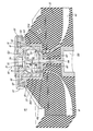
入口コントロールデバイス44の第1の実施形態が図5〜図11に示されている。入口デバイスは、両ポンプ41、42の流入量を調節するように機能する。入口コントロールデバイス44は、タイヤに形成されている受け器64内に挿入されている外側インサート60を含む。受け器64は、タイヤ内面上に形成されておりかつ生ゴムまたは生ゴムピラミッド状物体の一連の同心リングを使用してタイヤサイドウォール32に構築されているねじ付き内側穴部を任意選択で含んでいてもよい隆起したハンプである。あるいは、外側インサート60は、生ゴム(もしくはエラストマー材料)または生ゴムピラミッド状物体(もしくはエラストマー材料)の1つ以上の同心層により構成されておりかつ加硫中にタイヤに化学的に結合されている受け器の中心部内に挿入されていてよい。インサートは、生ゴム、エラストマー、ナイロン、真鍮もしくは金属もしくは超高分子量ポリエチレン(UHMWPE)、または当業者に既知の他の材料を含んでいてもよい。インサートは、レゾルシノールホルムアルデヒドラテックス(RFL)などのまたは当業者に既知の、一般的に「ディップ」と呼ばれる適切な接着剤で被覆されていることが好ましい。インサートの外面は粗くなっており、選択されたRFLで被覆されていてもよい。インサートの外面は、リッジ部、フランジ、拡張部、ねじ山、またはインサート60をタイヤサイドウォール32のゴム内に保持するために、選択されたRFLに加えて他の機械的手段をさらに含んでいてもよい。
A first embodiment of the
図6に示されている通り、外部インサート60は、タイヤ空洞部に面している開いた端部と、開いた端部の反対側の底壁62と、湾曲した側壁63とにより形成されている内側部分を有する。底壁は、底壁から延びている雄部65を有する。雄部は、バルブの内部に濾過した空気を送る、貫通する穴部66を有する。底部はまた、ポンプ通路41a、42aとの一致および流体連通のために、2つの対向穴部68、69を有する。ガスケット70が、インサート60の底壁62上に配置されている。ガスケットは、インサート60の3つの穴部66、68、69と一致した3つの穴部を備え、円形で平坦である。ガスケットはまた、3つの穴部(図示せず)の各々の周囲に突出リブを有するか、またはあるいは、3つのoリングがガスケット70の定位置に使用されていてもよい。入口コントロールデバイスは、図9〜図11に示されているバルブインサート80をさらに含む。バルブインサート80の外側本体81は、位置決めキー82が本体81から突出している状態で、ほぼ円筒形に形成されている。位置決めキーは、外側インサート60の壁63に形成されている位置決めスロット(図示せず)と嵌合係合して着座している。位置決めキー82は、バルブ本体の底面85上の穴部83、84がインサートの穴部68、69と確実に一致しているようにする。穴部83、84は、外側ポンプ通路41a、42aがバルブ本体80の内室88とインサート穴部68、69を介して流体連通しているように、バルブ本体の内室88と流体連通している。
As shown in FIG. 6, the
図6に示されている通り、圧膜90が、バルブ本体内室88の内部に設けられており、圧膜90の外側フランジ状リム92は、内室壁94の周囲に形成されている環状棚部91上にある。圧膜90はディスク形状であり、限定されないがゴム、エラストマー、プラスチック、またはシリコーンなどの可撓性材料から形成されていることが好ましい。圧膜のバルブ側93上には、プラグ96が膜から突出している。プラグは、チャネル103の穴部107を塞いで外気からの空気流が内室88内に入らないように、したがって、空気流がポンプ41、42内に入らないように配置されている。
As shown in FIG. 6, the
ばね98が、プラグ96に巻き付けられている第1の端部99と、内室の底壁105から延びているチャネル103に巻き付けられている第2の端部101とを有する。チャネル103は、雄部65の穴部66と一致している、貫通する穴部107を有する。穴部107および穴部66は、フィルタアセンブリ130と流体連通している。フィルタアセンブリ130は、タイヤの外側部分に、入口コントロールデバイスの反対側に取り付けられている。フィルタアセンブリは、外気を濾過しかつごみおよび流体がポンプに進入しないようにするフィルタ媒体を有する。フィルタアセンブリは、タイヤサイドウォール32に取り付けられている硬いプラスチックのカップ形状のデバイスで形成されていてもよく、バルブ本体80の内室88と流体連通している開口部を有していてもよい。
A
図9および図11に示されている通り、蓋部109が圧膜90を覆って配置されている。蓋部は、圧膜のリムに係合するフランジ状部分111を有する。蓋部109は中央穴部113をさらに含む。図8に示されている通り、蓋部109は、滑らすことが可能な保持器115により入口コントロールデバイス44に固定されている。保持器115は、対向する切欠き凹部119に最初に一致して、次いで回転してインサート60のフランジ状端部123の嵌合溝部121と係合する、対向するU形端部117を有する。保持器115は、穴部125を有し、圧膜とタイヤ空洞部との流体連通を可能にする。
As shown in FIGS. 9 and 11, the
圧膜90は、膜90の一方の側でタイヤ空洞部40の内部の圧力に対する応答性を有し、膜の他方の側で入口室内の圧力に対して応答性を有する。タイヤ空気圧が十分に高い場合、タイヤ空気圧は、膜のプラグ96を、ばね力を克服し、チャネルと封止係合するように押し、圧膜は、空気流がポンプ入口端部41a、42aに進入し得ないように、チャネル103からの流れを封止する。タイヤが設定圧力Psetまで空気圧を失うと、ばねは圧膜に十分な力をかけ、プラグをチャネルから退かせ、チャネル107を開く。次いで、外気がバルブ本体のチャネル107に進入してもよく、次いで、内室88を通り、穴部83、84の内の1つを出て、ポンプ入口端部41a、42aの1つに入る。
The
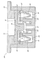
入口デバイス200の第2の実施形態が図12〜図13に示されている。第2の実施形態は、以下の差異を除いて入口デバイス44と同一である。第1のダックビルバルブ202および第2のダックビルバルブ204が、バルブ本体の内室88内に取り付けられている。単一の内室88は、3つの室205、206、208と交換されている。濾過された周囲空気が入口室205に進入する。第1のダックビルバルブおよび第2のダックビルバルブは、各室206、208の内部に設けられている。任意選択の流動制御平板207が、穴部209、211を位置合わせして、入口室からの流を(タイヤ回転方向に応じて)室206、208の1つ内に向かわせ、次いで、各ダックビルバルブ202、204の一方を通過させる。ダックビルバルブ202、204は、ポンプからバルブ内部への逆流を防止する。本発明はダックビルバルブに限定されず、チェックバルブとして機能する、当業者に既知の他のバルブが使用されてもよい。
A second embodiment of the
図2Aからわかるように、2つの180度ポンプ41、42が示されている。タイヤが回転方向88に回転すると、フットプリント100が地面98に当接して形成される。圧縮力104が、フットプリント100からタイヤ内に向けられ、数字106で示されているポンプ42のセグメント110を平らにするように作用する。ポンプ42のセグメント110を平らにすることにより、平らになったセグメント110と出口チェックバルブ46との間にある一部の空気が、矢印84で示されている方向に、チェックバルブ46の方へ押し進められる。タイヤが地面98に沿って方向88に回転し続けると、ポンプチューブ42は順次平らにされるか、または、タイヤ回転方向88と反対の方向90に、セグメント110、110’、110’’ずつ押し潰される。1つのセグメントずつポンプチューブ42の順次の平坦化により、平らになったセグメントとチェックバルブ46との間にある空気柱は、ポンプ42の内部で方向84に、出口デバイス46に、そしてタイヤ空洞部内に送られる。
As can be seen from FIG. 2A, two 180 degree pumps 41, 42 are shown. When the tire rotates in the
タイヤが方向88に回転していると、図2Aに示されている通り、平らになったチューブセグメントは、方向90にポンプチューブ42に沿って入口デバイス44、200に流入する空気92により、順次満たされる。方向90の、入口デバイス44、200からの空気の流入は、出口ポンプ端部が、タイヤ回転方向88で示されているように反時計周りに回転し、タイヤのフットプリント100を通過するまで継続する。
As the tire rotates in
図2Bは、そのような状態における蠕動ポンプアセンブリ14の方位を示す。図示の状態では、チューブ41は、数字106で示されている圧縮力104により、フットプリントの反対側で、セグメント102、102’、102’’ずつ順次平坦化され続けている。空気が、時計周り方向94に入口デバイス44までポンプで送られ、そこで、空気は、入口デバイス44から排気または排出される。このことは、ダックビルバルブのせいで、第2のデバイス200では不可能である。入口デバイス44からの排出空気96が、多孔質媒体内に蓄積した塵または粒子に関してフィルタ80を自浄するように作用するフィルタ80を通過する。入口デバイス44から外へポンプで送られた空気を排気すると、出口デバイスは閉鎖した状態にあり、空気はタイヤ空洞部40に出入りして流れない。タイヤが、入口デバイス44が(図2Aに示されている)タイヤフットプリント100を通過するまで、反時計周り方向88にさらに回転すると、空気流は出口デバイス46に向かって再開し、ポンプで送られた空気をタイヤ空洞部40へと外に流す(符号86参照)。
FIG. 2B shows the orientation of the
前述のサイクルは、次いで、タイヤ回転毎に繰り返され、各回転の半分でポンプで送られた空気がタイヤ空洞部へ進むことになり、回転の半分で、ポンプで送られた空気が入口デバイスフィルタ80から出て戻るように方向付けられてフィルタを自浄する。当然のことながら、タイヤ12の回転方向88は図2Aおよび図2Bに反時計周りであるように示されているが、主題のタイヤアセンブリ10およびその蠕動ポンプアセンブリ14は、数字88で示されている回転に対して(時計周り)逆回転方向に同様の方法で機能するであろう。したがって、蠕動ポンプは、前進回転方向または逆回転方向に動くタイヤアセンブリ14に関して双方向性であり、等しく機能的である。
The aforementioned cycle is then repeated for each tire revolution, with the pumped air going to the tire cavity at half of each revolution, and at half the revolution, the pumped air is fed into the inlet device filter. Directed to exit 80 and return to self-clean the filter. Of course, while the direction of
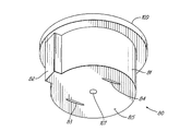
蠕動ポンプアセンブリ14の位置は図3〜図4から理解されるであろう。一実施形態では、蠕動ポンプアセンブリ14は、タイヤサイドウォール32の、チェーファ120内のリムフランジ面26の径方向外側に配置されている。そのように配置されているので、空気チューブ42は、タイヤフットプリント100から半径方向内側にあり、したがって、前述の通りタイヤフットプリントから向けられた力により平らになるように配置されている。フットプリント100の反対側のセグメントは、チューブセグメントをリムフランジ面26に押しつけるフットプリント100からの圧縮力114により平坦化される。チューブ42の配置は、タイヤのビード領域34のチェーファ120とリム面26との間に具体的に示されているが、これに限定されずサイドウォールまたはトレッドのどこかなどのタイヤの任意の領域に配置されていてもよい。
The position of the
上述から、空気通路41、42が1セグメントずつ平坦化しかつタイヤフットプリント100において閉じる自動膨張タイヤのための双方向蠕動ポンプを、本発明が提供していることは言うまでもない。入口コントロールバルブ44、200は、フィルタ80を含んでいてもよく、自浄式であってもよい。蠕動ポンプアセンブリ14は、空気をタイヤ空洞部40へポンプで送る回転の一方の半分と入口デバイス44(フィルタ80)から出て戻るように空気をポンプで送る回転の他方の半分のどちらかの方向のタイヤの回転下で、空気をポンプで送る。蠕動ポンプアセンブリ14は、システム故障検出器としての機能を果たす従来の構造の二次タイヤ空気圧監視システム(TPMS)(図示せず)と共に使用されてもよい。TPMSは、タイヤアセンブリの自動膨張システムにおける任意の故障を検出し、そのような状態のユーザに警報を出すのに使用されてもよい。
From the above, it goes without saying that the present invention provides a bi-directional peristaltic pump for self-inflating tires in which the
本発明における変形形態は、本明細書に示されている記載に照らして可能である。本発明を例示する目的で、ある代表的な実施形態および詳細が示されたが、本発明の範囲から逸脱することなく、本発明において種々の変更および修正を施し得ることが、当業者に明らかである。したがって、以下の添付の特許請求の範囲により定められる、本発明の完全に意図された範囲内に入る、記載されている特定の実施形態において変更を施し得ることを理解すべきである。 Variations in the present invention are possible in light of the description presented herein. For the purpose of illustrating the invention, certain representative embodiments and details have been shown, but it will be apparent to those skilled in the art that various changes and modifications can be made in the invention without departing from the scope of the invention. It is. Accordingly, it is to be understood that changes may be made in the particular embodiments described that fall within the full intended scope of the invention as defined by the following appended claims.
10 タイヤアセンブリ
12 タイヤ
32 サイドウォール
34 ビード領域
38 タイヤトレッド領域
40 タイヤ空洞部
41a,42a 入口端部
41b、42b 出口端部
44 入口デバイス
46 出口デバイス
60 外部インサート
66、68、69、83、84、107、125、209、211 穴部
80 バルブ本体
88 内室
90 圧膜
96 プラグ
98 ばね
100 フットプリント
103 チャネル
200 入口デバイス、
202、204 ダックビルバルブ
205、206、208 室
207 流動制御平板
DESCRIPTION OF
202, 204
Claims (31)
a.タイヤ空洞部と、第1のタイヤビード領域および第2のタイヤビード領域からそれぞれタイヤトレッド領域まで延びている第1のサイドウォールおよび第2のサイドウォールと、を有するタイヤと、
b.前記タイヤは、空気通路を有し、該空気通路は、入口端部および出口端部を有し、タイヤフットプリント付近では自体の一部が実質的に閉じることを可能にするように動作可能であり、該空気通路の前記出口端部は、前記タイヤ空洞部と流体連通していることと、
c.前記空気通路の前記入口端部に接続されている入口デバイスであって、前記タイヤ内に取り付けられたバルブ本体を含み、該バルブ本体が、前記タイヤ空洞部と流体連通し、前記空気通路の前記入口端部と流体連通している第1の穴部を有する内室、および周囲空気と流体連通しているチャネルを有する、入口デバイスと、
d.圧膜が、前記バルブ本体の前記内室の内部に設けられており、前記チャネルを開閉するように配置され、前記タイヤ空洞部および前記バルブ本体の前記内室と流体連通していることと、
e.ばねが、前記内室の内部に設けられており、前記圧膜に力を加えるように配置されていることと、
を特徴とする、自動膨張タイヤアセンブリ。 In self-expanding tire assemblies,
a. A tire having a tire cavity, and a first sidewall and a second sidewall extending from the first tire bead region and the second tire bead region to the tire tread region, respectively;
b. The tire has an air passage that has an inlet end and an outlet end and is operable to allow a portion of itself to be substantially closed near the tire footprint. And the outlet end of the air passage is in fluid communication with the tire cavity;
c. An inlet device connected to the inlet end of the air passage, comprising a valve body mounted in the tire, wherein the valve body is in fluid communication with the tire cavity and the air passage An inlet device having an inner chamber having a first bore in fluid communication with the inlet end and a channel in fluid communication with ambient air;
d. A pressure membrane is provided inside the inner chamber of the valve body, is arranged to open and close the channel, and is in fluid communication with the tire cavity and the inner chamber of the valve body;
e. A spring is provided inside the inner chamber and is arranged to apply a force to the pressure film;
A self-inflating tire assembly, characterized by:
a.タイヤ空洞部と、第1のタイヤビード領域および第2のタイヤビード領域からそれぞれタイヤトレッド領域まで延びている第1のサイドウォールおよび第2のサイドウォールと、を有するタイヤと、
b.前記タイヤは、空気通路を有し、該空気通路は、入口端部および出口端部を有し、タイヤフットプリント付近では自体の一部が実質的に閉じることを可能にするように動作可能であり、該空気通路の前記出口端部は、前記タイヤ空洞部と流体連通していることと、
c.前記空気通路の端部に接続されているバルブデバイスであって、前記タイヤ内に取り付けられているインサートと、前記バルブインサートの内部に取り付けられているバルブ本体と、を含み、該バルブ本体は、前記空気通路の前記端部と流体連通している第1の穴部を有する内室、および周囲空気と流体連通しているチャネルを有する、バルブデバイスと、
を特徴とする、自動膨張タイヤアセンブリ。 In self-expanding tire assemblies,
a. A tire having a tire cavity, and a first sidewall and a second sidewall extending from the first tire bead region and the second tire bead region to the tire tread region, respectively;
b. The tire has an air passage that has an inlet end and an outlet end and is operable to allow a portion of itself to be substantially closed near the tire footprint. And the outlet end of the air passage is in fluid communication with the tire cavity;
c. A valve device connected to an end of the air passage, comprising: an insert mounted in the tire; and a valve body mounted inside the valve insert, the valve body comprising: A valve device having an inner chamber having a first bore in fluid communication with the end of the air passage and a channel in fluid communication with ambient air;
A self-inflating tire assembly, characterized by:
a.タイヤ空洞部と第1のタイヤビード領域および第2のタイヤビード領域からそれぞれタイヤトレッド領域まで延びている第1のサイドウォールおよび第2のサイドウォールと、を有するタイヤと、
b.前記タイヤは、第1の空気通路および第2の空気通路を有し、前記第1の空気通路および前記第2の空気通路は、出口端部および入口端部をそれぞれ有し、タイヤフットプリント付近では自体の一部が実質的に閉じることを可能にするように動作可能であり、前記第1の空気通路および前記第2の空気通路の前記出口端部は、前記タイヤ空洞部と流体連通していることと、
c.前記第1の空気通路および前記第2の空気通路の前記入口端部に接続されているバルブデバイスであって、前記タイヤ内に取り付けられているインサートと、前記バルブインサートの内部に取り付けられ、第1の室、第2の室および第3の室を有するバルブ本体と、を含み、前記第1の室は、前記第1の空気通路の前記入口端部と流体連通している第1の穴部を有し、前記第2の室は、前記第2の空気通路の前記入口端部と流体連通している第2の穴部を有し、前記第3の室は周囲空気と流体連通している、バルブデバイスと、
d.第1のチェックバルブおよび第2のチェックバルブが、前記第1の空気通路および前記第2の空気通路からそれぞれ前記第1の室および前記第2の室内への流体の逆流を防止するように、前記第1の室および前記第2の室内に配置されていることと、
e.圧膜が、前記バルブ本体の内部に設けられており、前記第3の室を開閉するように配置されていることと、
を特徴とする、自動膨張タイヤアセンブリ。 In self-inflating tire assemblies,
a. A tire having a tire cavity, a first sidewall and a second sidewall extending from the first tire bead region and the second tire bead region to a tire tread region, respectively;
b. The tire has a first air passage and a second air passage, and the first air passage and the second air passage have an outlet end and an inlet end, respectively, and near the tire footprint. Wherein the outlet ends of the first air passage and the second air passage are in fluid communication with the tire cavity. And
c. A valve device connected to the inlet end of the first air passage and the second air passage, wherein the insert is mounted in the tire; A valve body having a first chamber, a second chamber, and a third chamber, wherein the first chamber is in fluid communication with the inlet end of the first air passage. The second chamber has a second hole in fluid communication with the inlet end of the second air passage, and the third chamber is in fluid communication with ambient air. A valve device,
d. The first check valve and the second check valve prevent back flow of fluid from the first air passage and the second air passage to the first chamber and the second chamber, respectively; Being disposed in the first chamber and the second chamber;
e. A pressure membrane is provided inside the valve body and is arranged to open and close the third chamber;
A self-inflating tire assembly, characterized by:
a.前記タイヤ内に取り付けられているインサートと、前記バルブインサートの内部に取り付けられ、第1の室、第2の室および第3の室を有するバルブ本体と、を含み、第1のチェックバルブおよび第2のチェックバルブが、前記第1の室および前記第2の室内に配置されていることと、
b.圧膜が、前記バルブ本体の内部に設けられ、前記第3の室を開閉するように配置されていることと、
c.前記圧膜は、前記タイヤ空洞部および前記バルブ本体の前記第3の室と流体連通していることと、
d.ばねが、前記第3の室の内部に設けられており、前記圧膜に力を加えて、開いた状態にある前記チャネルに対する圧膜位置を付勢するように配置されていることと、
を特徴とする、バルブデバイス。 In valve devices for tires,
a. An insert mounted in the tire; and a valve body mounted in the valve insert and having a first chamber, a second chamber, and a third chamber, wherein the first check valve and the first check valve Two check valves are disposed in the first chamber and the second chamber;
b. A pressure film is provided inside the valve body and is arranged to open and close the third chamber;
c. The pressure membrane is in fluid communication with the tire cavity and the third chamber of the valve body;
d. A spring is disposed within the third chamber and is arranged to apply a force to the pressure film to bias the pressure film position relative to the open channel;
Features a valve device.
a.前記タイヤ内に取り付けられているインサートと、バルブ本体が、前記バルブインサートの内部に取り付けられており、単一の室を有するバルブ本体と、を含んでいることと、
b.圧膜が、前記バルブ本体の室の内部に設けられ、外気と流体連通しているチャネルを開閉するように配置されていることと、
c.前記圧膜は前記タイヤと流体連通していることと、
d.ばねが、前記室の内部に設けられており、前記圧膜に力を加えて、開いた状態にある前記チャネルに対する圧膜位置を付勢するように配置されていることと、
を特徴とする、バルブデバイス。 In valve devices for tires,
a. Including an insert mounted in the tire, and a valve body mounted inside the valve insert and having a single chamber;
b. A pressure membrane is provided inside the chamber of the valve body and is arranged to open and close a channel in fluid communication with outside air;
c. The pressure membrane is in fluid communication with the tire;
d. A spring is disposed within the chamber and is arranged to apply a force to the pressure film to bias the pressure film position relative to the channel in an open state;
Features a valve device.
Applications Claiming Priority (4)
| Application Number | Priority Date | Filing Date | Title |
|---|---|---|---|
| US201261739843P | 2012-12-20 | 2012-12-20 | |
| US61/739,843 | 2012-12-20 | ||
| US13/783,948 US9242518B2 (en) | 2012-12-20 | 2013-03-04 | Compact valve system for self-inflating tire |
| US13/783,948 | 2013-03-04 |
Publications (2)
| Publication Number | Publication Date |
|---|---|
| JP2014122022A true JP2014122022A (en) | 2014-07-03 |
| JP2014122022A5 JP2014122022A5 (en) | 2017-02-02 |
Family
ID=49884915
Family Applications (1)
| Application Number | Title | Priority Date | Filing Date |
|---|---|---|---|
| JP2013259061A Pending JP2014122022A (en) | 2012-12-20 | 2013-12-16 | Compact valve system for self-inflating tire |
Country Status (5)
| Country | Link |
|---|---|
| US (1) | US9242518B2 (en) |
| EP (1) | EP2746072B1 (en) |
| JP (1) | JP2014122022A (en) |
| CN (1) | CN103879244B (en) |
| BR (1) | BR102013032202A2 (en) |
Cited By (2)
| Publication number | Priority date | Publication date | Assignee | Title |
|---|---|---|---|---|
| JP2015113119A (en) * | 2013-12-11 | 2015-06-22 | ザ・グッドイヤー・タイヤ・アンド・ラバー・カンパニーThe Goodyear Tire & Rubber Company | Self-inflating tire with hybrid pump |
| JP2015117015A (en) * | 2013-12-17 | 2015-06-25 | ザ・グッドイヤー・タイヤ・アンド・ラバー・カンパニーThe Goodyear Tire & Rubber Company | Bidirectional self-expansion tire having pressure regulator |
Families Citing this family (13)
| Publication number | Priority date | Publication date | Assignee | Title |
|---|---|---|---|---|
| US11453258B2 (en) | 2013-03-12 | 2022-09-27 | Aperia Technologies, Inc. | System for tire inflation |
| US9340077B2 (en) * | 2013-12-09 | 2016-05-17 | The Goodyear Tire & Rubber Company | Air compressor for a pneumatic tire and a tire comprising a compressor mounted within the tire's cavity |
| US9365084B2 (en) * | 2013-12-11 | 2016-06-14 | The Goodyear Tire & Rubber Company | Self-inflating tire and pressure regulator |
| US9662944B2 (en) | 2013-12-23 | 2017-05-30 | The Goodyear Tire & Rubber Company | Self inflating tire with pressure regulator |
| WO2015105848A2 (en) * | 2014-01-07 | 2015-07-16 | Eaton Corporation | Self-inflating tire air regulator |
| US9327562B2 (en) * | 2014-05-05 | 2016-05-03 | The Goodyear Tire & Rubber Company | Air maintenance tire assembly |
| US9387737B2 (en) * | 2014-08-07 | 2016-07-12 | The Goodyear Tire & Rubber Company | Passage tube for air maintenance tire |
| US9744816B2 (en) | 2014-08-12 | 2017-08-29 | The Goodyear Tire & Rubber Company | Air maintenance tire |
| US9783015B2 (en) | 2014-08-12 | 2017-10-10 | The Goodyear Tire & Rubber Company | Control regulator and pumping system for an air maintenance tire |
| US10322611B2 (en) * | 2016-12-16 | 2019-06-18 | The Goodyear Tire & Rubber Company | System for an air maintenance tire assembly |
| US10807422B2 (en) | 2016-12-22 | 2020-10-20 | The Goodyear Tire & Rubber Company | Inlet control valve for an air maintenance tire |
| US11285764B2 (en) | 2016-12-22 | 2022-03-29 | The Goodyear Tire & Rubber Company | Control valve for an air maintenance tire |
| US11642920B2 (en) | 2018-11-27 | 2023-05-09 | Aperia Technologies, Inc. | Hub-integrated inflation system |
Citations (3)
| Publication number | Priority date | Publication date | Assignee | Title |
|---|---|---|---|---|
| JP2011126527A (en) * | 2009-12-21 | 2011-06-30 | Goodyear Tire & Rubber Co:The | Self-inflating tire assembly |
| JP2012111484A (en) * | 2010-11-22 | 2012-06-14 | Goodyear Tire & Rubber Co:The | In-line pump assembly for self-inflating tire |
| JP2012201363A (en) * | 2011-03-23 | 2012-10-22 | Goodyear Tire & Rubber Co:The | Hydraulic membrane pump assembly for air maintaining tire |
Family Cites Families (32)
| Publication number | Priority date | Publication date | Assignee | Title |
|---|---|---|---|---|
| US1050886A (en) * | 1910-02-23 | 1913-01-21 | Anson B Wetherell | Vehicle-tire. |
| US1250476A (en) | 1915-11-10 | 1917-12-18 | Oscar Hammersmith | Safety-valve mechanism and signal for pneumatic tires. |
| US1413531A (en) | 1921-11-03 | 1922-04-18 | K S Conrad Company | Tire alarm and gauge |
| US2095489A (en) * | 1934-09-13 | 1937-10-12 | Cotton George Albert | Pneumatic tire |
| US2634785A (en) * | 1949-05-02 | 1953-04-14 | Margaret L Tubbs | Vehicle tire |
| GB1086512A (en) * | 1964-02-24 | 1967-10-11 | Ronald Leslie Sheppard | Improvements in or relating to pneumatic tyres |
| US3247882A (en) * | 1964-05-20 | 1966-04-26 | Armstrong Rubber Co | Sidewall valve for tubeless tires |
| DE2632622A1 (en) * | 1975-07-25 | 1977-02-10 | Dunlop Ltd | TIRE |
| DE2627529A1 (en) | 1976-06-18 | 1977-12-29 | Helmut Schmidt | PRESSURE DISPLAYING DUST CAP FOR PNEUMATIC TIRES |
| US4601254A (en) | 1983-03-24 | 1986-07-22 | Huang Chung Siung | Tire pressure warning device |
| GB2255850B (en) | 1991-05-15 | 1994-11-16 | Huang Tien Tsai | Low pressure indicating device for a pneumatic tire |
| US5856619A (en) | 1997-05-13 | 1999-01-05 | Wang; Kuo-Tsai | Tire pressure indicator |
| US5957151A (en) * | 1998-01-23 | 1999-09-28 | Dalcourt; Rene | Automatic pressure regulating valve |
| US6531960B1 (en) | 1999-12-30 | 2003-03-11 | Peter Gladstone | Low tire pressure indicator |
| US6595046B2 (en) | 2000-03-10 | 2003-07-22 | Gary Lemberger | Temperature and pressure compensating indicator |
| US6525655B2 (en) | 2001-06-28 | 2003-02-25 | Tien-Tsai Huang | Diaphragm-type tire pressure indicator |
| US20040112495A1 (en) * | 2002-12-09 | 2004-06-17 | Curtis Arlen Weise | Self inflating tire |
| DE10335244A1 (en) * | 2003-08-01 | 2005-03-10 | Bayerische Motoren Werke Ag | Device for air filling a rotating pneumatic tire |
| US6911903B2 (en) | 2003-08-07 | 2005-06-28 | Tagg Technology Corp. | Tire pressure indicator |
| US20050072349A1 (en) | 2003-08-08 | 2005-04-07 | Mike Perlin | Tire pressure indicator |
| US7131632B2 (en) | 2003-08-18 | 2006-11-07 | Kloehn Co., Ltd. | Microfluidic two-way isolation valve |
| US7667583B2 (en) | 2006-02-13 | 2010-02-23 | Measurement Ltd. | Tire pressure gauge |
| CZ303718B6 (en) * | 2006-05-23 | 2013-04-03 | Sithold S.R.O. | Retentivity component for adjusting pneumatic tyre pressure and process for producing thereof |
| US7421889B2 (en) | 2006-12-01 | 2008-09-09 | Pao-Hung Lin | Tire pressure warning assembly having a biasing member |
| US7493808B2 (en) | 2007-02-12 | 2009-02-24 | John Kostin Milanovich | Fill-through tire pressure indicator |
| US7764168B1 (en) | 2007-05-04 | 2010-07-27 | Mobiletron Electronics Co., Ltd. | Tire pressure monitoring system with a capped tire valve |
| US8701726B2 (en) | 2011-08-30 | 2014-04-22 | The Goodyear Tire & Rubber Company | Self-inflating tire |
| US8573270B2 (en) | 2011-08-30 | 2013-11-05 | The Goodyear Tire & Rubber Company | Self-inflating tire and pressure regulator |
| US8857484B2 (en) | 2011-08-30 | 2014-10-14 | The Goodyear Tire & Rubber Company | Self-inflating tire |
| US8991456B2 (en) * | 2012-06-28 | 2015-03-31 | The Goodyear Tire & Rubber Company | Reversible air maintenance tire and pump assembly |
| US9108476B2 (en) * | 2012-07-19 | 2015-08-18 | The Goodyear Tire & Rubber Company | Bypass air maintenance tire and pump assembly |
| US9205714B2 (en) | 2012-12-20 | 2015-12-08 | The Goodyear Tire & Rubber Company | Compact valve system for self-inflating tire |
-
2013
- 2013-03-04 US US13/783,948 patent/US9242518B2/en active Active
- 2013-12-12 EP EP13196788.7A patent/EP2746072B1/en active Active
- 2013-12-13 BR BRBR102013032202-4A patent/BR102013032202A2/en not_active Application Discontinuation
- 2013-12-16 JP JP2013259061A patent/JP2014122022A/en active Pending
- 2013-12-20 CN CN201310707388.4A patent/CN103879244B/en active Active
Patent Citations (3)
| Publication number | Priority date | Publication date | Assignee | Title |
|---|---|---|---|---|
| JP2011126527A (en) * | 2009-12-21 | 2011-06-30 | Goodyear Tire & Rubber Co:The | Self-inflating tire assembly |
| JP2012111484A (en) * | 2010-11-22 | 2012-06-14 | Goodyear Tire & Rubber Co:The | In-line pump assembly for self-inflating tire |
| JP2012201363A (en) * | 2011-03-23 | 2012-10-22 | Goodyear Tire & Rubber Co:The | Hydraulic membrane pump assembly for air maintaining tire |
Cited By (2)
| Publication number | Priority date | Publication date | Assignee | Title |
|---|---|---|---|---|
| JP2015113119A (en) * | 2013-12-11 | 2015-06-22 | ザ・グッドイヤー・タイヤ・アンド・ラバー・カンパニーThe Goodyear Tire & Rubber Company | Self-inflating tire with hybrid pump |
| JP2015117015A (en) * | 2013-12-17 | 2015-06-25 | ザ・グッドイヤー・タイヤ・アンド・ラバー・カンパニーThe Goodyear Tire & Rubber Company | Bidirectional self-expansion tire having pressure regulator |
Also Published As
| Publication number | Publication date |
|---|---|
| CN103879244B (en) | 2017-09-26 |
| US20140174620A1 (en) | 2014-06-26 |
| BR102013032202A2 (en) | 2014-09-02 |
| EP2746072A1 (en) | 2014-06-25 |
| EP2746072B1 (en) | 2019-03-27 |
| US9242518B2 (en) | 2016-01-26 |
| CN103879244A (en) | 2014-06-25 |
Similar Documents
| Publication | Publication Date | Title |
|---|---|---|
| US9242518B2 (en) | Compact valve system for self-inflating tire | |
| US9205714B2 (en) | Compact valve system for self-inflating tire | |
| JP5911402B2 (en) | Self-inflating tire | |
| US9381780B2 (en) | Compact valve system for self-inflating tire | |
| US8857484B2 (en) | Self-inflating tire | |
| US9126462B2 (en) | Compact valve system for self-inflating tire | |
| US8573270B2 (en) | Self-inflating tire and pressure regulator | |
| US9327561B2 (en) | Compact valve system for self-inflating tire | |
| US9327560B2 (en) | Compact valve system for self-inflating tire | |
| US20150165841A1 (en) | Self-inflating tire with pressure regulator | |
| US9233582B2 (en) | Self-inflating tire with inlet control valve | |
| JP2018105501A (en) | Inlet control valve for air maintenance tire |
Legal Events
| Date | Code | Title | Description |
|---|---|---|---|
| RD04 | Notification of resignation of power of attorney |
Free format text: JAPANESE INTERMEDIATE CODE: A7424 Effective date: 20140416 |
|
| A521 | Request for written amendment filed |
Free format text: JAPANESE INTERMEDIATE CODE: A523 Effective date: 20161216 |
|
| A621 | Written request for application examination |
Free format text: JAPANESE INTERMEDIATE CODE: A621 Effective date: 20161216 |
|
| A977 | Report on retrieval |
Free format text: JAPANESE INTERMEDIATE CODE: A971007 Effective date: 20171026 |
|
| A131 | Notification of reasons for refusal |
Free format text: JAPANESE INTERMEDIATE CODE: A131 Effective date: 20171031 |
|
| A601 | Written request for extension of time |
Free format text: JAPANESE INTERMEDIATE CODE: A601 Effective date: 20180131 |
|
| A02 | Decision of refusal |
Free format text: JAPANESE INTERMEDIATE CODE: A02 Effective date: 20180703 |