EP2883718A1 - Self-inflating tire with hybrid pump - Google Patents
Self-inflating tire with hybrid pump Download PDFInfo
- Publication number
- EP2883718A1 EP2883718A1 EP14196685.3A EP14196685A EP2883718A1 EP 2883718 A1 EP2883718 A1 EP 2883718A1 EP 14196685 A EP14196685 A EP 14196685A EP 2883718 A1 EP2883718 A1 EP 2883718A1
- Authority
- EP
- European Patent Office
- Prior art keywords
- tire
- air
- passageway
- inlet
- air tube
- Prior art date
- Legal status (The legal status is an assumption and is not a legal conclusion. Google has not performed a legal analysis and makes no representation as to the accuracy of the status listed.)
- Granted
Links
- 238000004891 communication Methods 0.000 claims abstract description 19
- 239000012530 fluid Substances 0.000 claims abstract description 19
- 239000000463 material Substances 0.000 claims abstract description 7
- 239000011324 bead Substances 0.000 claims abstract description 6
- 230000002572 peristaltic effect Effects 0.000 description 8
- 238000005086 pumping Methods 0.000 description 6
- 230000007246 mechanism Effects 0.000 description 3
- 230000002457 bidirectional effect Effects 0.000 description 2
- 230000001419 dependent effect Effects 0.000 description 2
- 238000013461 design Methods 0.000 description 2
- 229920001971 elastomer Polymers 0.000 description 2
- 238000012544 monitoring process Methods 0.000 description 2
- 238000013459 approach Methods 0.000 description 1
- 230000008901 benefit Effects 0.000 description 1
- 238000004140 cleaning Methods 0.000 description 1
- 150000001875 compounds Chemical class 0.000 description 1
- 238000010276 construction Methods 0.000 description 1
- 230000008602 contraction Effects 0.000 description 1
- 238000009792 diffusion process Methods 0.000 description 1
- 239000000806 elastomer Substances 0.000 description 1
- 239000000446 fuel Substances 0.000 description 1
- 230000037361 pathway Effects 0.000 description 1
- 229920003023 plastic Polymers 0.000 description 1
- 230000009467 reduction Effects 0.000 description 1
- 230000000246 remedial effect Effects 0.000 description 1
- 238000004513 sizing Methods 0.000 description 1
- 238000012546 transfer Methods 0.000 description 1
- 238000004073 vulcanization Methods 0.000 description 1
Images


Classifications
-
- B—PERFORMING OPERATIONS; TRANSPORTING
- B60—VEHICLES IN GENERAL
- B60C—VEHICLE TYRES; TYRE INFLATION; TYRE CHANGING; CONNECTING VALVES TO INFLATABLE ELASTIC BODIES IN GENERAL; DEVICES OR ARRANGEMENTS RELATED TO TYRES
- B60C23/00—Devices for measuring, signalling, controlling, or distributing tyre pressure or temperature, specially adapted for mounting on vehicles; Arrangement of tyre inflating devices on vehicles, e.g. of pumps or of tanks; Tyre cooling arrangements
- B60C23/10—Arrangement of tyre-inflating pumps mounted on vehicles
- B60C23/12—Arrangement of tyre-inflating pumps mounted on vehicles operated by a running wheel
- B60C23/121—Arrangement of tyre-inflating pumps mounted on vehicles operated by a running wheel the pumps being mounted on the tyres
- B60C23/123—Elongate peristaltic pumps
-
- B—PERFORMING OPERATIONS; TRANSPORTING
- B60—VEHICLES IN GENERAL
- B60C—VEHICLE TYRES; TYRE INFLATION; TYRE CHANGING; CONNECTING VALVES TO INFLATABLE ELASTIC BODIES IN GENERAL; DEVICES OR ARRANGEMENTS RELATED TO TYRES
- B60C23/00—Devices for measuring, signalling, controlling, or distributing tyre pressure or temperature, specially adapted for mounting on vehicles; Arrangement of tyre inflating devices on vehicles, e.g. of pumps or of tanks; Tyre cooling arrangements
- B60C23/10—Arrangement of tyre-inflating pumps mounted on vehicles
- B60C23/12—Arrangement of tyre-inflating pumps mounted on vehicles operated by a running wheel
- B60C23/135—Arrangement of tyre-inflating pumps mounted on vehicles operated by a running wheel activated due to tyre deformation
-
- Y—GENERAL TAGGING OF NEW TECHNOLOGICAL DEVELOPMENTS; GENERAL TAGGING OF CROSS-SECTIONAL TECHNOLOGIES SPANNING OVER SEVERAL SECTIONS OF THE IPC; TECHNICAL SUBJECTS COVERED BY FORMER USPC CROSS-REFERENCE ART COLLECTIONS [XRACs] AND DIGESTS
- Y10—TECHNICAL SUBJECTS COVERED BY FORMER USPC
- Y10T—TECHNICAL SUBJECTS COVERED BY FORMER US CLASSIFICATION
- Y10T152/00—Resilient tires and wheels
- Y10T152/10—Tires, resilient
- Y10T152/10495—Pneumatic tire or inner tube
Definitions
- the invention relates generally to self-inflating tires and, more specifically, to a pump mechanism for such tires.
- Tire Pressure Monitoring Systems have been proposed to warn drivers when tire pressure is significantly low. Such systems, however, remain dependent upon the driver taking remedial action when warned to re-inflate a tire to recommended pressure. It is a desirable, therefore, to incorporate a self-inflating feature within a tire that will self-inflate the tire in order to compensate for any reduction in tire pressure over time without the need for driver intervention.
- One type of self inflating tire feature is a peristaltic pump assembly. If the pump is annular or 360 degrees in length, it will not be bidirectional unless there is additional valving. The use of 2 180 degree pumps allow the system to be bidrectional. This is because only one pump works when the tire rotates in one direction, and the other pump works when the tire rotates in the opposite direction.
- the invention relates to a tire assembly in accordance with claim 1.
- a self-inflating tire assembly comprising a tire such as a tire mounted to a rim.
- the tire has a tire cavity, first and second sidewalls extending respectively from first and second tire bead regions to a tire tread region, a first air tube mounted in the tire and defining an air passageway, the air tube being composed of a flexible material operative to allow a portion of the air tube segment near a tire footprint to close the annular passageway, the first air tube having an inlet and an outlet, a second air tube mounted in the tire and defining an air passageway, the air tube being composed of a flexible material operative to allow a portion of the air tube near a tire footprint to close the annular passageway, the second air tube having an inlet and an outlet, wherein the inlet of the first air tube is connected to the inlet of the second air tube by an inlet device, wherein the inlet device is in fluid communication with the outside air, wherein the inlet of the first air tube is in fluid communication with the
- Axial and “axially” means lines or directions that are parallel to the axis of rotation of the tire.
- “Circumferential” means lines or directions extending along the perimeter of the surface of the annular tread perpendicular to the axial direction.
- Equatorial Centerplane means the plane perpendicular to the tire's axis of rotation and passing through the center of the tread.
- “Footprint” means the contact patch or area of contact of the tire tread with a flat surface at zero speed and under normal load and pressure.
- “Lateral” means an axial direction.
- “Lateral edges” means a line tangent to the axially outermost tread contact patch or footprint as measured under normal load and tire inflation, the lines being parallel to the equatorial centerplane.
- Periodaltic means operating by means of wave-like contractions that propel contained matter, such as air, along tubular pathways.
- Ring and radially means directions radially toward or away from the axis of rotation of the tire.
- a tire assembly 10 includes a tire 12 and a peristaltic pump assembly 14.
- the assembly 10 may further comprise a tire rim 28.
- the tire mounts in a conventional fashion to a pair of rim mounting surfaces 18 located adjacent outer rim flanges 22.
- the tire rim 28 includes an annular rim body 21 that joins the rim flanges 22 and supports the tire assembly as shown.
- the tire is essentially of conventional construction unless described otherwise hereinafter, having a pair of sidewalls 30 extending from opposite bead areas 34 to a crown or tire tread region 38.
- the tire and rim enclose a tire cavity 40.
- the peristaltic pump assembly 14 includes a first and second pump 41, 42 that are mounted in a passageway 43 located in the sidewall area of the tire, preferably near the bead region.
- the air passageway is preferably molded into the sidewall of the tire during vulcanization and is preferably annular in shape.
- Each pump 41, 42 has a first end 41 a, 42a joined together by an inlet device 44 and a second end 41 b, 42b joined together by an outlet device 46.
- Each pump 41, 42 is comprised of a tube formed of a resilient, flexible material such as plastic, elastomer or rubber compounds, and is capable of withstanding repeated deformation cycles when the tube is deformed into a flattened condition subject to external force and, upon removal of such force, returns to an original condition generally circular in cross-section.
- the tube is of a diameter sufficient to operatively pass a volume of air sufficient for the purposes described herein and allowing a positioning of the tube in an operable location within the tire assembly as will be described.
- the tube has a circular cross-sectional shape, although other shapes such as elliptical may be utilized.
- the inlet device 44 and the outlet device 46 are spaced apart approximately 180 degrees at respective locations.
- the outlet device 46 is a T shaped connector having a body 47 having a first port 48 that connects to pump 41 outlet end 41 b.
- the first port 48 is in fluid communication with outlet port 52.
- Outlet port 52 extends into the tire cavity so that the pump end 41 b is in fluid communication with the tire cavity.
- the outlet device further includes a second port 50 that connects to pump 42 outlet end 42b.
- the second port 50 is also connected to outlet port 52, so that the pump end 42 is in fluid communication with the tire cavity.
- first port 48 and second port 50 further include a directional one way valve 56, 58 to prevent backflow of tire cavity air into the pump.
- the directional one way valve 56, 58 may be a check valve.
- the directional one way valves 56, 58 also prevent flow from pump 41 to pump 42 and vice versa. This is critical to prevent short circuiting of the two pumps and ensure that the air is pumped into the tire cavity.
- a first embodiment of an inlet device 44 is shown in Figure 4 .
- the inlet device functions to regulate the inlet flow of both pumps 41, 42.
- the inlet device 44 includes a T shaped body 60 that may be molded into a green tire and then cured.
- the T shaped body has a first port 62 that connects to the inlet end 41 a of pump 41.
- the T shaped body has a second port 64 that connects to the inlet end 42a of pump 42.
- the first port 62 and second port 64 are in fluid communication with each other with passageway 63.
- the T shaped body has an inlet passageway 66 that is in fluid communication with passageway 63, first port 62 and second port 64.
- the inlet passageway 66 has a one way valve 68 positioned in the passageway 66.
- the inlet passageway 66 is connected to an optional filter assembly 69 that houses a filter media.
- the inlet passageway 66 and the optional filter assembly 69 is in fluid communication with the outside air.
- the one way valve 68 prevents flow from either pump 41, 42 from exiting the inlet assembly through passageway 66 and then through the filter assembly 69.
- Figures 6-8 illustrate the hybrid pump device during operation.
- the tire has been removed for clarity.
- Figure 6 illustrates the direction of tire rotation as being counterclockwise.
- pump tube 42 is compressed at point P.
- compressed air in pump tube 42 is released into the tire cavity through outlet device 46.
- Figure 7 when the tire pressure point P is located on pump 41, the compressed pump air is routed towards the inlet device 46.
- the inlet device 46 functions as connector to allow the compressed air to flow through passageway 63 which joins pump 41 to pump 42.
- the compressed air continues through pump 42 to outlet device 46 and then into the tire cavity 40.
- the one way valve 68 prevents pumped air from escaping the inlet control device 44.
- the inlet device allows air to enter the inlet device 44 of the hybrid pump assembly when the inlet device 44 has rotated past the tire footprint, as shown in Figures 6 and 8 .
- the pumps 41, 42 will fill with air only during 1 ⁇ 2 a tire rotation, when the inlet has rotated past the footprint and prior to rotation past the outlet.
- the hybrid pump assembly of the invention functions as a 360 degree pump, thus allowing both 180 degree pumps 41, 42 to pump during rotation in either direction.
- the hybrid pump of the invention overcomes this disadvantage.
- the hybrid pump of the invention has a pumping rate equivalent to a 360 degree pump, because the inlet device connects the two 180 degree pumps together to transfer flow from one pump to the other as shown in Figure 7 .
- the hybrid pump can pump like a 360 degree pump if the tire rotates in either direction, as shown in Figures 6-8 .
- the 360 degree hybrid pump of the invention allows for a greater pumping rate and a higher pressure to be reached when pumping, as compared to a 180 degree pump. This is really the main advantage of the hybrid design, it combines the best aspects from both approaches, the bi-directionality and the greater pumping capacity.
- the peristaltic pump assembly 14 is positioned in the tire sidewall. So positioned, the air tube 41, 42 is radially inward from the tire footprint 100 and is thus positioned to be flattened by forces directed from the tire footprint as described above. The segment that is opposite the footprint 100 will flatten from the compressive force from the footprint compressing the tube segment.
- the positioning of the pump tube 41, 42 is specifically shown as being located in the bead region of the tire, it is not limited to same, and may be located at any region of the tire undergoing a compressive force, such as anywhere in the sidewall or tread.
- the diametric sizing of the peristaltic pump air tube 41, 42 is selected to span the circumference of the rim flange surface 26, although it is not limited to same.
- the subject invention provides a bi-directionally peristaltic pump for a self-inflating tire in which a circular air tube flattens segment by segment and closes in the tire footprint.
- the air inlet T-device 44 may include a filter and be self-cleaning.
- the air inlet device 44 may be coupled to a pressure regulator, such as disclosed in US-A-2013/0048178 , which is hereby incorporated by reference.
- the peristaltic pump assembly 14 may be used with a secondary tire pressure monitoring system (TPMS) (not shown) of conventional configuration that serves as a system fault detector.
- TPMS secondary tire pressure monitoring system
- the TPMS may be used to detect any fault in the self-inflation system of the tire assembly and alert the user of such a condition.
Abstract
Description
- The invention relates generally to self-inflating tires and, more specifically, to a pump mechanism for such tires.
- Normal air diffusion reduces tire pressure over time. The natural state of tires is under inflated. Accordingly, drivers must repeatedly act to maintain tire pressures or they will see reduced fuel economy, tire life and reduced vehicle braking and handling performance. Tire Pressure Monitoring Systems have been proposed to warn drivers when tire pressure is significantly low. Such systems, however, remain dependent upon the driver taking remedial action when warned to re-inflate a tire to recommended pressure. It is a desirable, therefore, to incorporate a self-inflating feature within a tire that will self-inflate the tire in order to compensate for any reduction in tire pressure over time without the need for driver intervention.
- One type of self inflating tire feature is a peristaltic pump assembly. If the pump is annular or 360 degrees in length, it will not be bidirectional unless there is additional valving. The use of 2 180 degree pumps allow the system to be bidrectional. This is because only one pump works when the tire rotates in one direction, and the other pump works when the tire rotates in the opposite direction.
- Thus it is desired to have a simple pump design that is bidirectional and can pump 360 degrees without the need for complicated valving.
- The invention relates to a tire assembly in accordance with claim 1.
- Dependent claims refer to preferred embodiments of the invention.
- In a preferred aspect of the invention, a self-inflating tire assembly is provided comprising a tire such as a tire mounted to a rim. The tire has a tire cavity, first and second sidewalls extending respectively from first and second tire bead regions to a tire tread region, a first air tube mounted in the tire and defining an air passageway, the air tube being composed of a flexible material operative to allow a portion of the air tube segment near a tire footprint to close the annular passageway, the first air tube having an inlet and an outlet, a second air tube mounted in the tire and defining an air passageway, the air tube being composed of a flexible material operative to allow a portion of the air tube near a tire footprint to close the annular passageway, the second air tube having an inlet and an outlet, wherein the inlet of the first air tube is connected to the inlet of the second air tube by an inlet device, wherein the inlet device is in fluid communication with the outside air, wherein the inlet of the first air tube is in fluid communication with the inlet of the second air tube, wherein the outlet of the first air tube and the second air tube is in fluid communication with the tire cavity.
- "Axial" and "axially" means lines or directions that are parallel to the axis of rotation of the tire.
- "Circumferential" means lines or directions extending along the perimeter of the surface of the annular tread perpendicular to the axial direction.
- "Equatorial Centerplane (CP)" means the plane perpendicular to the tire's axis of rotation and passing through the center of the tread.
- "Footprint" means the contact patch or area of contact of the tire tread with a flat surface at zero speed and under normal load and pressure.
- "Lateral" means an axial direction.
- "Lateral edges" means a line tangent to the axially outermost tread contact patch or footprint as measured under normal load and tire inflation, the lines being parallel to the equatorial centerplane.
- "Peristaltic" means operating by means of wave-like contractions that propel contained matter, such as air, along tubular pathways.
- "Radial" and "radially" means directions radially toward or away from the axis of rotation of the tire.
- The invention will be described by way of example and with reference to the accompanying drawings in which:
-
FIG. 1 is an exploded view of the hybrid pump mechanism and tire of the present invention. -
FIG. 2 is a front view of the hybrid pump and tire mechanism ofFig. 1 . -
FIG. 3 is a front view of the hybrid pump assembly. -
FIG. 4 is a front view of the inlet assembly. -
FIG. 5 is a front view of the hybrid pump outlet assembly. -
FIGS. 6 and7 illustrate the hybrid pump operation when the tire rotates in the counterclockwise direction. -
Fig. 8 illustrates the hybrid pump operation when the tire rotates in the clockwise direction. -
FIG. 9 is an enlarged cross sectional view of the tire and rim assembly with the pump system shown mounted in the tire. - Referring to
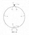
FIG. 1 , atire assembly 10 includes atire 12 and aperistaltic pump assembly 14. Theassembly 10 may further comprise atire rim 28. As shown inFig. 9 , the tire mounts in a conventional fashion to a pair ofrim mounting surfaces 18 located adjacentouter rim flanges 22. Thetire rim 28 includes anannular rim body 21 that joins therim flanges 22 and supports the tire assembly as shown. The tire is essentially of conventional construction unless described otherwise hereinafter, having a pair ofsidewalls 30 extending fromopposite bead areas 34 to a crown ortire tread region 38. The tire and rim enclose atire cavity 40. - As shown in
FIGS. 1-3 , theperistaltic pump assembly 14 includes a first andsecond pump passageway 43 located in the sidewall area of the tire, preferably near the bead region. The air passageway is preferably molded into the sidewall of the tire during vulcanization and is preferably annular in shape. Eachpump first end inlet device 44 and asecond end outlet device 46. Eachpump - As shown in
Figure 3 , theinlet device 44 and theoutlet device 46 are spaced apart approximately 180 degrees at respective locations. As shown inFigure 5 , theoutlet device 46 is a T shaped connector having abody 47 having afirst port 48 that connects topump 41outlet end 41 b. Thefirst port 48 is in fluid communication withoutlet port 52.Outlet port 52 extends into the tire cavity so that thepump end 41 b is in fluid communication with the tire cavity. The outlet device further includes asecond port 50 that connects topump 42outlet end 42b. Thesecond port 50 is also connected tooutlet port 52, so that thepump end 42 is in fluid communication with the tire cavity.Fig 5 further illustrates thatfirst port 48 andsecond port 50 further include a directional oneway valve way valve way valves pump 41 to pump 42 and vice versa. This is critical to prevent short circuiting of the two pumps and ensure that the air is pumped into the tire cavity. - A first embodiment of an
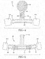
inlet device 44 is shown inFigure 4 . The inlet device functions to regulate the inlet flow of bothpumps inlet device 44 includes a Tshaped body 60 that may be molded into a green tire and then cured. The T shaped body has afirst port 62 that connects to theinlet end 41 a ofpump 41. The T shaped body has asecond port 64 that connects to theinlet end 42a ofpump 42. Thefirst port 62 andsecond port 64 are in fluid communication with each other withpassageway 63. The T shaped body has aninlet passageway 66 that is in fluid communication withpassageway 63,first port 62 andsecond port 64. Theinlet passageway 66 has a oneway valve 68 positioned in thepassageway 66. Theinlet passageway 66 is connected to anoptional filter assembly 69 that houses a filter media. Theinlet passageway 66 and theoptional filter assembly 69 is in fluid communication with the outside air. The oneway valve 68 prevents flow from eitherpump passageway 66 and then through thefilter assembly 69. -
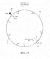
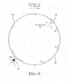
Figures 6-8 illustrate the hybrid pump device during operation. The tire has been removed for clarity.Figure 6 illustrates the direction of tire rotation as being counterclockwise. As the tire rotates counterclockwise,pump tube 42 is compressed at point P. As the tire rotates counterclockwise, compressed air inpump tube 42 is released into the tire cavity throughoutlet device 46. As shown inFigure 7 , when the tire pressure point P is located onpump 41, the compressed pump air is routed towards theinlet device 46. Theinlet device 46 functions as connector to allow the compressed air to flow throughpassageway 63 which joinspump 41 to pump 42. The compressed air continues throughpump 42 tooutlet device 46 and then into thetire cavity 40. Thus the two separate pumps function as one. The oneway valve 68 prevents pumped air from escaping theinlet control device 44. - The inlet device allows air to enter the
inlet device 44 of the hybrid pump assembly when theinlet device 44 has rotated past the tire footprint, as shown inFigures 6 and8 . Thus thepumps - Thus as described above, the hybrid pump assembly of the invention functions as a 360 degree pump, thus allowing both 180 degree pumps 41, 42 to pump during rotation in either direction. Typically, when two 180 degree pumps are used for bi-directional pumping, only one pump is actually pumping. The pump not being used will pump when the tire is rotated in the opposite direction. The hybrid pump of the invention overcomes this disadvantage. The hybrid pump of the invention has a pumping rate equivalent to a 360 degree pump, because the inlet device connects the two 180 degree pumps together to transfer flow from one pump to the other as shown in
Figure 7 . In addition, the hybrid pump can pump like a 360 degree pump if the tire rotates in either direction, as shown inFigures 6-8 . The 360 degree hybrid pump of the invention allows for a greater pumping rate and a higher pressure to be reached when pumping, as compared to a 180 degree pump. This is really the main advantage of the hybrid design, it combines the best aspects from both approaches, the bi-directionality and the greater pumping capacity. - In one embodiment, the
peristaltic pump assembly 14 is positioned in the tire sidewall. So positioned, theair tube pump tube pump air tube - From the forgoing, it will be appreciated that the subject invention provides a bi-directionally peristaltic pump for a self-inflating tire in which a circular air tube flattens segment by segment and closes in the tire footprint. The air inlet T-
device 44 may include a filter and be self-cleaning. Theair inlet device 44 may be coupled to a pressure regulator, such as disclosed inUS-A-2013/0048178 , which is hereby incorporated by reference. Theperistaltic pump assembly 14 may be used with a secondary tire pressure monitoring system (TPMS) (not shown) of conventional configuration that serves as a system fault detector. The TPMS may be used to detect any fault in the self-inflation system of the tire assembly and alert the user of such a condition.
Claims (15)
- A self-inflating tire assembly comprising a tire (10) having a tire cavity (40), first and second sidewalls extending respectively from first and second tire bead regions (34) to a tire tread region (38) and further comprising:(i) a first air tube defining an air passageway, the first air tube being composed of a flexible material operative to allow a portion of the air tube segment near a tire footprint to close the passageway, the first air tube having an inlet and an outlet;a second air tube defining an air passageway, the second air tube being composed of a flexible material operative to allow a portion of the air tube segment near a tire footprint to close the passageway, the second air tube having an inlet and an outlet;wherein the inlet of the first air tube is in fluid communication with the inlet of the second air tube; andwherein the outlet of the first air tube and the second air tube is in fluid communication with the tire cavity; or(ii) a first air passageway integrally formed in the tire, the first air passageway being operative to allow a portion of the first air passageway near a tire footprint to open and close, the first air passageway having an inlet and an outlet;a second air passageway integrally formed in the tire, the second air passageway being operative to allow a portion of the second air passageway near a tire footprint to open and close, the second air passageway having an inlet and an outlet;wherein the inlet of the first air passageway is in fluid communication with the inlet of the second air passageway; andwherein the outlet of the first air passageway and the second air passageway is in fluid communication with the tire cavity.
- The tire assembly of claim 1 wherein the inlet of the first air tube or the first air passageway is connected to the inlet of the second air tube or the second air tube passageway by an inlet device.
- The tire assembly of claim 1 or 2 wherein the inlet device has an inlet in fluid communication with the outside air.
- The tire assembly of at least one of the previous claims, wherein the first and second air tube is sequentially flattened by the tire footprint to pump air along the air passageway in either a forward tire direction of rotation or a reverse tire direction of rotation.
- The tire assembly of at least one of the previous claims, wherein the first and second air passageway is sequentially flattened by the tire footprint to pump air along the air passageway in either a forward tire direction of rotation or a reverse tire direction of rotation.
- The tire assembly of at least one of the previous claims, wherein the inlet device further comprises a one way valve (56, 68).
- The tire assembly of at least one of the previous claims, wherein the inlet device further comprises an inlet passageway in fluid communication with the outside air, wherein a one way valve is positioned in the inlet passageway.
- The tire assembly of at least one of the previous claims, wherein there is no one way valve between the inlet of the first air tube or the first air passageway and the inlet of the second air tube or the second air passageway.
- The tire assembly of at least one of the previous claims wherein the inlet device is a T shaped body (60) having a first port (62) connected to the inlet end of the first air tube or the first air passageway, and a second port (64) connected to an inlet end of the second air tube or the second air passageway, wherein the first port and the second port are joined together by a passageway.
- The tire assembly of claim 9 wherein the T shaped body (60) further comprises a third port in fluid communication with the outside air, and wherein the third point is joined to the passageway.
- The tire assembly of claim 9 wherein a one way valve is positioned in the third port between the passageway and the outside air inlet.
- The tire assembly of at least one of the previous claims, further comprising an outlet device, wherein the outlet ends of the first and second air tube or of the first and second air passageway are in fluid communication with the tire cavity.
- The tire assembly of at least one of the previous claims wherein the outlet end of the first tube or the first air passageway has a one way valve (58).
- The tire assembly of at least one of the previous claims wherein the outlet end of the second tube or the second air passageway has a one way valve.
- The tire assembly of at least one of the previous claims, wherein the outlet device and the inlet device are about 180 degrees apart.
Applications Claiming Priority (1)
| Application Number | Priority Date | Filing Date | Title |
|---|---|---|---|
| US14/103,176 US9409454B2 (en) | 2013-12-11 | 2013-12-11 | Self-inflating tire with hybrid pump |
Publications (2)
| Publication Number | Publication Date |
|---|---|
| EP2883718A1 true EP2883718A1 (en) | 2015-06-17 |
| EP2883718B1 EP2883718B1 (en) | 2016-07-20 |
Family
ID=52021018
Family Applications (1)
| Application Number | Title | Priority Date | Filing Date |
|---|---|---|---|
| EP14196685.3A Active EP2883718B1 (en) | 2013-12-11 | 2014-12-08 | Self-inflating tire with hybrid pump |
Country Status (5)
| Country | Link |
|---|---|
| US (1) | US9409454B2 (en) |
| EP (1) | EP2883718B1 (en) |
| JP (1) | JP2015113119A (en) |
| CN (1) | CN104709013B (en) |
| BR (1) | BR102014029928A2 (en) |
Families Citing this family (5)
| Publication number | Priority date | Publication date | Assignee | Title |
|---|---|---|---|---|
| US9809066B2 (en) | 2014-05-05 | 2017-11-07 | The Goodyear Tire & Rubber Company | System for an air maintenance tire assembly |
| CN108349340B (en) * | 2015-08-14 | 2021-03-26 | 科达创新有限股份公司 | Tire condition or vehicle monitoring system and method |
| KR101871301B1 (en) * | 2016-12-16 | 2018-06-26 | 넥센타이어 주식회사 | Pneumatic tire having rim protector |
| US10183535B1 (en) | 2017-07-21 | 2019-01-22 | Pygmalion Technologies LLC | Air motion powered devices for vehicle wheels |
| US10759236B2 (en) | 2017-05-04 | 2020-09-01 | The Goodyear Tire & Rubber Company | Wheel for an air maintenance tire system |
Citations (4)
| Publication number | Priority date | Publication date | Assignee | Title |
|---|---|---|---|---|
| DE3433318A1 (en) * | 1984-09-11 | 1986-03-20 | Mousiol, Hans, 6000 Frankfurt | Method for inflating pneumatic tyres and pneumatic tyre for the method |
| EP2343200A2 (en) * | 2009-12-21 | 2011-07-13 | The Goodyear Tire & Rubber Company | Self-inflating tire |
| US20130048178A1 (en) | 2011-08-30 | 2013-02-28 | The Goodyear Tire & Rubber Company | Self-inflating tire |
| EP2746072A1 (en) * | 2012-12-20 | 2014-06-25 | The Goodyear Tire & Rubber Company | Compact valve system for self-inflating tire |
Family Cites Families (7)
| Publication number | Priority date | Publication date | Assignee | Title |
|---|---|---|---|---|
| JP2007302118A (en) * | 2006-05-11 | 2007-11-22 | Chonosuke Hirano | Tire automatic inflator device |
| JP2009119940A (en) * | 2007-11-13 | 2009-06-04 | Nissan Diesel Motor Co Ltd | Rotary pump |
| US8534335B2 (en) * | 2010-09-27 | 2013-09-17 | The Goodyear Tire & Rubber Company | Distributed pump self-inflating tire assembly |
| US8322036B2 (en) * | 2010-11-22 | 2012-12-04 | The Goodyear Tire & Rubber Company | Method of manufacturing a self-inflating tire |
| US8746306B2 (en) * | 2011-11-09 | 2014-06-10 | The Goodyear Tire & Rubber Company | Self-inflating tire |
| US8820369B2 (en) * | 2011-11-09 | 2014-09-02 | The Goodyear Tire & Rubber Company | Self-inflating tire |
| US8991456B2 (en) * | 2012-06-28 | 2015-03-31 | The Goodyear Tire & Rubber Company | Reversible air maintenance tire and pump assembly |
-
2013
- 2013-12-11 US US14/103,176 patent/US9409454B2/en active Active
-
2014
- 2014-11-28 BR BR102014029928A patent/BR102014029928A2/en not_active IP Right Cessation
- 2014-12-08 EP EP14196685.3A patent/EP2883718B1/en active Active
- 2014-12-10 JP JP2014249812A patent/JP2015113119A/en active Pending
- 2014-12-11 CN CN201410754643.5A patent/CN104709013B/en active Active
Patent Citations (4)
| Publication number | Priority date | Publication date | Assignee | Title |
|---|---|---|---|---|
| DE3433318A1 (en) * | 1984-09-11 | 1986-03-20 | Mousiol, Hans, 6000 Frankfurt | Method for inflating pneumatic tyres and pneumatic tyre for the method |
| EP2343200A2 (en) * | 2009-12-21 | 2011-07-13 | The Goodyear Tire & Rubber Company | Self-inflating tire |
| US20130048178A1 (en) | 2011-08-30 | 2013-02-28 | The Goodyear Tire & Rubber Company | Self-inflating tire |
| EP2746072A1 (en) * | 2012-12-20 | 2014-06-25 | The Goodyear Tire & Rubber Company | Compact valve system for self-inflating tire |
Also Published As
| Publication number | Publication date |
|---|---|
| CN104709013B (en) | 2017-05-17 |
| BR102014029928A2 (en) | 2016-01-05 |
| US20150158352A1 (en) | 2015-06-11 |
| CN104709013A (en) | 2015-06-17 |
| EP2883718B1 (en) | 2016-07-20 |
| JP2015113119A (en) | 2015-06-22 |
| US9409454B2 (en) | 2016-08-09 |
Similar Documents
| Publication | Publication Date | Title |
|---|---|---|
| EP2565061B1 (en) | Self-inflating tire and pressure regulator device | |
| EP2565060B1 (en) | Self-inflating tire | |
| EP2343200B1 (en) | Self-inflating tire | |
| EP2384912B1 (en) | Self-inflating tire assembly | |
| EP2565059B1 (en) | Pneumatic tire | |
| US8960249B2 (en) | Self-inflating tire | |
| EP2886374B1 (en) | Self-inflatng tire with pressure regulator | |
| EP2746073B1 (en) | Compact valve system for a self-inflating tire | |
| US9381780B2 (en) | Compact valve system for self-inflating tire | |
| EP2740616B1 (en) | Air maintenance pumping assembly and tire | |
| US8826955B2 (en) | Air maintenance pumping assembly and tire | |
| EP2746072B1 (en) | Compact valve system for self-inflating tire | |
| US9061556B2 (en) | Air maintenance pneumatic tire | |
| EP2883718B1 (en) | Self-inflating tire with hybrid pump | |
| EP2746075A2 (en) | Compact valve system for self-inflating tire | |
| EP2886373B1 (en) | Bi-directional self-inflating tire with pressure regulator | |
| EP2886372B1 (en) | Self-inflating tire with inlet control valve | |
| EP3031633B1 (en) | Air maintenance tire and valve assembly | |
| EP3112192A1 (en) | Tire | |
| US20160052350A1 (en) | Air maintenance pumping assembly and tire | |
| US9604511B2 (en) | Air maintenance pumping assembly and tire |
Legal Events
| Date | Code | Title | Description |
|---|---|---|---|
| PUAI | Public reference made under article 153(3) epc to a published international application that has entered the european phase |
Free format text: ORIGINAL CODE: 0009012 |
|
| 17P | Request for examination filed |
Effective date: 20141208 |
|
| AK | Designated contracting states |
Kind code of ref document: A1 Designated state(s): AL AT BE BG CH CY CZ DE DK EE ES FI FR GB GR HR HU IE IS IT LI LT LU LV MC MK MT NL NO PL PT RO RS SE SI SK SM TR |
|
| AX | Request for extension of the european patent |
Extension state: BA ME |
|
| R17P | Request for examination filed (corrected) |
Effective date: 20151217 |
|
| RBV | Designated contracting states (corrected) |
Designated state(s): AL AT BE BG CH CY CZ DE DK EE ES FI FR GB GR HR HU IE IS IT LI LT LU LV MC MK MT NL NO PL PT RO RS SE SI SK SM TR |
|
| GRAP | Despatch of communication of intention to grant a patent |
Free format text: ORIGINAL CODE: EPIDOSNIGR1 |
|
| INTG | Intention to grant announced |
Effective date: 20160224 |
|
| GRAS | Grant fee paid |
Free format text: ORIGINAL CODE: EPIDOSNIGR3 |
|
| GRAA | (expected) grant |
Free format text: ORIGINAL CODE: 0009210 |
|
| AK | Designated contracting states |
Kind code of ref document: B1 Designated state(s): AL AT BE BG CH CY CZ DE DK EE ES FI FR GB GR HR HU IE IS IT LI LT LU LV MC MK MT NL NO PL PT RO RS SE SI SK SM TR |
|
| REG | Reference to a national code |
Ref country code: GB Ref legal event code: FG4D |
|
| REG | Reference to a national code |
Ref country code: CH Ref legal event code: EP |
|
| REG | Reference to a national code |
Ref country code: IE Ref legal event code: FG4D |
|
| REG | Reference to a national code |
Ref country code: AT Ref legal event code: REF Ref document number: 813749 Country of ref document: AT Kind code of ref document: T Effective date: 20160815 |
|
| REG | Reference to a national code |
Ref country code: DE Ref legal event code: R096 Ref document number: 602014002771 Country of ref document: DE |
|
| REG | Reference to a national code |
Ref country code: LT Ref legal event code: MG4D |
|
| REG | Reference to a national code |
Ref country code: FR Ref legal event code: PLFP Year of fee payment: 3 |
|
| REG | Reference to a national code |
Ref country code: NL Ref legal event code: MP Effective date: 20160720 |
|
| REG | Reference to a national code |
Ref country code: AT Ref legal event code: MK05 Ref document number: 813749 Country of ref document: AT Kind code of ref document: T Effective date: 20160720 |
|
| PG25 | Lapsed in a contracting state [announced via postgrant information from national office to epo] |
Ref country code: NO Free format text: LAPSE BECAUSE OF FAILURE TO SUBMIT A TRANSLATION OF THE DESCRIPTION OR TO PAY THE FEE WITHIN THE PRESCRIBED TIME-LIMIT Effective date: 20161020 Ref country code: HR Free format text: LAPSE BECAUSE OF FAILURE TO SUBMIT A TRANSLATION OF THE DESCRIPTION OR TO PAY THE FEE WITHIN THE PRESCRIBED TIME-LIMIT Effective date: 20160720 Ref country code: LT Free format text: LAPSE BECAUSE OF FAILURE TO SUBMIT A TRANSLATION OF THE DESCRIPTION OR TO PAY THE FEE WITHIN THE PRESCRIBED TIME-LIMIT Effective date: 20160720 Ref country code: IS Free format text: LAPSE BECAUSE OF FAILURE TO SUBMIT A TRANSLATION OF THE DESCRIPTION OR TO PAY THE FEE WITHIN THE PRESCRIBED TIME-LIMIT Effective date: 20161120 Ref country code: NL Free format text: LAPSE BECAUSE OF FAILURE TO SUBMIT A TRANSLATION OF THE DESCRIPTION OR TO PAY THE FEE WITHIN THE PRESCRIBED TIME-LIMIT Effective date: 20160720 Ref country code: RS Free format text: LAPSE BECAUSE OF FAILURE TO SUBMIT A TRANSLATION OF THE DESCRIPTION OR TO PAY THE FEE WITHIN THE PRESCRIBED TIME-LIMIT Effective date: 20160720 Ref country code: FI Free format text: LAPSE BECAUSE OF FAILURE TO SUBMIT A TRANSLATION OF THE DESCRIPTION OR TO PAY THE FEE WITHIN THE PRESCRIBED TIME-LIMIT Effective date: 20160720 |
|
| PG25 | Lapsed in a contracting state [announced via postgrant information from national office to epo] |
Ref country code: ES Free format text: LAPSE BECAUSE OF FAILURE TO SUBMIT A TRANSLATION OF THE DESCRIPTION OR TO PAY THE FEE WITHIN THE PRESCRIBED TIME-LIMIT Effective date: 20160720 Ref country code: BE Free format text: LAPSE BECAUSE OF FAILURE TO SUBMIT A TRANSLATION OF THE DESCRIPTION OR TO PAY THE FEE WITHIN THE PRESCRIBED TIME-LIMIT Effective date: 20160720 Ref country code: AT Free format text: LAPSE BECAUSE OF FAILURE TO SUBMIT A TRANSLATION OF THE DESCRIPTION OR TO PAY THE FEE WITHIN THE PRESCRIBED TIME-LIMIT Effective date: 20160720 Ref country code: PT Free format text: LAPSE BECAUSE OF FAILURE TO SUBMIT A TRANSLATION OF THE DESCRIPTION OR TO PAY THE FEE WITHIN THE PRESCRIBED TIME-LIMIT Effective date: 20161121 Ref country code: GR Free format text: LAPSE BECAUSE OF FAILURE TO SUBMIT A TRANSLATION OF THE DESCRIPTION OR TO PAY THE FEE WITHIN THE PRESCRIBED TIME-LIMIT Effective date: 20161021 Ref country code: LV Free format text: LAPSE BECAUSE OF FAILURE TO SUBMIT A TRANSLATION OF THE DESCRIPTION OR TO PAY THE FEE WITHIN THE PRESCRIBED TIME-LIMIT Effective date: 20160720 Ref country code: SE Free format text: LAPSE BECAUSE OF FAILURE TO SUBMIT A TRANSLATION OF THE DESCRIPTION OR TO PAY THE FEE WITHIN THE PRESCRIBED TIME-LIMIT Effective date: 20160720 Ref country code: PL Free format text: LAPSE BECAUSE OF FAILURE TO SUBMIT A TRANSLATION OF THE DESCRIPTION OR TO PAY THE FEE WITHIN THE PRESCRIBED TIME-LIMIT Effective date: 20160720 |
|
| REG | Reference to a national code |
Ref country code: DE Ref legal event code: R097 Ref document number: 602014002771 Country of ref document: DE |
|
| PG25 | Lapsed in a contracting state [announced via postgrant information from national office to epo] |
Ref country code: RO Free format text: LAPSE BECAUSE OF FAILURE TO SUBMIT A TRANSLATION OF THE DESCRIPTION OR TO PAY THE FEE WITHIN THE PRESCRIBED TIME-LIMIT Effective date: 20160720 Ref country code: EE Free format text: LAPSE BECAUSE OF FAILURE TO SUBMIT A TRANSLATION OF THE DESCRIPTION OR TO PAY THE FEE WITHIN THE PRESCRIBED TIME-LIMIT Effective date: 20160720 |
|
| PLBE | No opposition filed within time limit |
Free format text: ORIGINAL CODE: 0009261 |
|
| STAA | Information on the status of an ep patent application or granted ep patent |
Free format text: STATUS: NO OPPOSITION FILED WITHIN TIME LIMIT |
|
| PG25 | Lapsed in a contracting state [announced via postgrant information from national office to epo] |
Ref country code: SM Free format text: LAPSE BECAUSE OF FAILURE TO SUBMIT A TRANSLATION OF THE DESCRIPTION OR TO PAY THE FEE WITHIN THE PRESCRIBED TIME-LIMIT Effective date: 20160720 Ref country code: SK Free format text: LAPSE BECAUSE OF FAILURE TO SUBMIT A TRANSLATION OF THE DESCRIPTION OR TO PAY THE FEE WITHIN THE PRESCRIBED TIME-LIMIT Effective date: 20160720 Ref country code: DK Free format text: LAPSE BECAUSE OF FAILURE TO SUBMIT A TRANSLATION OF THE DESCRIPTION OR TO PAY THE FEE WITHIN THE PRESCRIBED TIME-LIMIT Effective date: 20160720 Ref country code: CZ Free format text: LAPSE BECAUSE OF FAILURE TO SUBMIT A TRANSLATION OF THE DESCRIPTION OR TO PAY THE FEE WITHIN THE PRESCRIBED TIME-LIMIT Effective date: 20160720 Ref country code: BG Free format text: LAPSE BECAUSE OF FAILURE TO SUBMIT A TRANSLATION OF THE DESCRIPTION OR TO PAY THE FEE WITHIN THE PRESCRIBED TIME-LIMIT Effective date: 20161020 |
|
| 26N | No opposition filed |
Effective date: 20170421 |
|
| PG25 | Lapsed in a contracting state [announced via postgrant information from national office to epo] |
Ref country code: SI Free format text: LAPSE BECAUSE OF FAILURE TO SUBMIT A TRANSLATION OF THE DESCRIPTION OR TO PAY THE FEE WITHIN THE PRESCRIBED TIME-LIMIT Effective date: 20160720 |
|
| PG25 | Lapsed in a contracting state [announced via postgrant information from national office to epo] |
Ref country code: MC Free format text: LAPSE BECAUSE OF FAILURE TO SUBMIT A TRANSLATION OF THE DESCRIPTION OR TO PAY THE FEE WITHIN THE PRESCRIBED TIME-LIMIT Effective date: 20160720 |
|
| REG | Reference to a national code |
Ref country code: IE Ref legal event code: MM4A |
|
| PG25 | Lapsed in a contracting state [announced via postgrant information from national office to epo] |
Ref country code: LU Free format text: LAPSE BECAUSE OF NON-PAYMENT OF DUE FEES Effective date: 20161208 |
|
| REG | Reference to a national code |
Ref country code: FR Ref legal event code: PLFP Year of fee payment: 4 |
|
| PG25 | Lapsed in a contracting state [announced via postgrant information from national office to epo] |
Ref country code: IE Free format text: LAPSE BECAUSE OF NON-PAYMENT OF DUE FEES Effective date: 20161208 |
|
| PG25 | Lapsed in a contracting state [announced via postgrant information from national office to epo] |
Ref country code: HU Free format text: LAPSE BECAUSE OF FAILURE TO SUBMIT A TRANSLATION OF THE DESCRIPTION OR TO PAY THE FEE WITHIN THE PRESCRIBED TIME-LIMIT; INVALID AB INITIO Effective date: 20141208 |
|
| PG25 | Lapsed in a contracting state [announced via postgrant information from national office to epo] |
Ref country code: CY Free format text: LAPSE BECAUSE OF FAILURE TO SUBMIT A TRANSLATION OF THE DESCRIPTION OR TO PAY THE FEE WITHIN THE PRESCRIBED TIME-LIMIT Effective date: 20160720 Ref country code: MK Free format text: LAPSE BECAUSE OF FAILURE TO SUBMIT A TRANSLATION OF THE DESCRIPTION OR TO PAY THE FEE WITHIN THE PRESCRIBED TIME-LIMIT Effective date: 20160720 |
|
| REG | Reference to a national code |
Ref country code: CH Ref legal event code: PL |
|
| PG25 | Lapsed in a contracting state [announced via postgrant information from national office to epo] |
Ref country code: MT Free format text: LAPSE BECAUSE OF NON-PAYMENT OF DUE FEES Effective date: 20161208 |
|
| PG25 | Lapsed in a contracting state [announced via postgrant information from national office to epo] |
Ref country code: AL Free format text: LAPSE BECAUSE OF FAILURE TO SUBMIT A TRANSLATION OF THE DESCRIPTION OR TO PAY THE FEE WITHIN THE PRESCRIBED TIME-LIMIT Effective date: 20160720 Ref country code: TR Free format text: LAPSE BECAUSE OF FAILURE TO SUBMIT A TRANSLATION OF THE DESCRIPTION OR TO PAY THE FEE WITHIN THE PRESCRIBED TIME-LIMIT Effective date: 20160720 |
|
| PG25 | Lapsed in a contracting state [announced via postgrant information from national office to epo] |
Ref country code: LI Free format text: LAPSE BECAUSE OF NON-PAYMENT OF DUE FEES Effective date: 20171231 Ref country code: CH Free format text: LAPSE BECAUSE OF NON-PAYMENT OF DUE FEES Effective date: 20171231 |
|
| GBPC | Gb: european patent ceased through non-payment of renewal fee |
Effective date: 20181208 |
|
| PG25 | Lapsed in a contracting state [announced via postgrant information from national office to epo] |
Ref country code: GB Free format text: LAPSE BECAUSE OF NON-PAYMENT OF DUE FEES Effective date: 20181208 |
|
| PGFP | Annual fee paid to national office [announced via postgrant information from national office to epo] |
Ref country code: FR Payment date: 20230929 Year of fee payment: 10 |
|
| PGFP | Annual fee paid to national office [announced via postgrant information from national office to epo] |
Ref country code: IT Payment date: 20231110 Year of fee payment: 10 Ref country code: DE Payment date: 20231010 Year of fee payment: 10 |