EP2746019B1 - Verfahren und Vorrichtung zum Herstellen von Werkstücken aus Faserhalbzeugen - Google Patents
Verfahren und Vorrichtung zum Herstellen von Werkstücken aus Faserhalbzeugen Download PDFInfo
- Publication number
- EP2746019B1 EP2746019B1 EP13196019.7A EP13196019A EP2746019B1 EP 2746019 B1 EP2746019 B1 EP 2746019B1 EP 13196019 A EP13196019 A EP 13196019A EP 2746019 B1 EP2746019 B1 EP 2746019B1
- Authority
- EP
- European Patent Office
- Prior art keywords
- binder
- mould
- moulding tool
- impregnated
- fibrous product
- Prior art date
- Legal status (The legal status is an assumption and is not a legal conclusion. Google has not performed a legal analysis and makes no representation as to the accuracy of the status listed.)
- Active
Links
Images
Classifications
-
- B—PERFORMING OPERATIONS; TRANSPORTING
- B29—WORKING OF PLASTICS; WORKING OF SUBSTANCES IN A PLASTIC STATE IN GENERAL
- B29C—SHAPING OR JOINING OF PLASTICS; SHAPING OF MATERIAL IN A PLASTIC STATE, NOT OTHERWISE PROVIDED FOR; AFTER-TREATMENT OF THE SHAPED PRODUCTS, e.g. REPAIRING
- B29C70/00—Shaping composites, i.e. plastics material comprising reinforcements, fillers or preformed parts, e.g. inserts
- B29C70/04—Shaping composites, i.e. plastics material comprising reinforcements, fillers or preformed parts, e.g. inserts comprising reinforcements only, e.g. self-reinforcing plastics
- B29C70/28—Shaping operations therefor
- B29C70/40—Shaping or impregnating by compression not applied
- B29C70/42—Shaping or impregnating by compression not applied for producing articles of definite length, i.e. discrete articles
- B29C70/46—Shaping or impregnating by compression not applied for producing articles of definite length, i.e. discrete articles using matched moulds, e.g. for deforming sheet moulding compounds [SMC] or prepregs
-
- B—PERFORMING OPERATIONS; TRANSPORTING
- B29—WORKING OF PLASTICS; WORKING OF SUBSTANCES IN A PLASTIC STATE IN GENERAL
- B29B—PREPARATION OR PRETREATMENT OF THE MATERIAL TO BE SHAPED; MAKING GRANULES OR PREFORMS; RECOVERY OF PLASTICS OR OTHER CONSTITUENTS OF WASTE MATERIAL CONTAINING PLASTICS
- B29B11/00—Making preforms
- B29B11/14—Making preforms characterised by structure or composition
- B29B11/16—Making preforms characterised by structure or composition comprising fillers or reinforcement
-
- B—PERFORMING OPERATIONS; TRANSPORTING
- B29—WORKING OF PLASTICS; WORKING OF SUBSTANCES IN A PLASTIC STATE IN GENERAL
- B29C—SHAPING OR JOINING OF PLASTICS; SHAPING OF MATERIAL IN A PLASTIC STATE, NOT OTHERWISE PROVIDED FOR; AFTER-TREATMENT OF THE SHAPED PRODUCTS, e.g. REPAIRING
- B29C33/00—Moulds or cores; Details thereof or accessories therefor
- B29C33/02—Moulds or cores; Details thereof or accessories therefor with incorporated heating or cooling means
- B29C33/04—Moulds or cores; Details thereof or accessories therefor with incorporated heating or cooling means using liquids, gas or steam
-
- B—PERFORMING OPERATIONS; TRANSPORTING
- B29—WORKING OF PLASTICS; WORKING OF SUBSTANCES IN A PLASTIC STATE IN GENERAL
- B29C—SHAPING OR JOINING OF PLASTICS; SHAPING OF MATERIAL IN A PLASTIC STATE, NOT OTHERWISE PROVIDED FOR; AFTER-TREATMENT OF THE SHAPED PRODUCTS, e.g. REPAIRING
- B29C70/00—Shaping composites, i.e. plastics material comprising reinforcements, fillers or preformed parts, e.g. inserts
- B29C70/04—Shaping composites, i.e. plastics material comprising reinforcements, fillers or preformed parts, e.g. inserts comprising reinforcements only, e.g. self-reinforcing plastics
- B29C70/28—Shaping operations therefor
- B29C70/54—Component parts, details or accessories; Auxiliary operations, e.g. feeding or storage of prepregs or SMC after impregnation or during ageing
- B29C70/56—Tensioning reinforcements before or during shaping
-
- B—PERFORMING OPERATIONS; TRANSPORTING
- B29—WORKING OF PLASTICS; WORKING OF SUBSTANCES IN A PLASTIC STATE IN GENERAL
- B29C—SHAPING OR JOINING OF PLASTICS; SHAPING OF MATERIAL IN A PLASTIC STATE, NOT OTHERWISE PROVIDED FOR; AFTER-TREATMENT OF THE SHAPED PRODUCTS, e.g. REPAIRING
- B29C35/00—Heating, cooling or curing, e.g. crosslinking or vulcanising; Apparatus therefor
- B29C35/02—Heating or curing, e.g. crosslinking or vulcanizing during moulding, e.g. in a mould
- B29C35/04—Heating or curing, e.g. crosslinking or vulcanizing during moulding, e.g. in a mould using liquids, gas or steam
- B29C35/045—Heating or curing, e.g. crosslinking or vulcanizing during moulding, e.g. in a mould using liquids, gas or steam using gas or flames
- B29C2035/046—Heating or curing, e.g. crosslinking or vulcanizing during moulding, e.g. in a mould using liquids, gas or steam using gas or flames dried air
Definitions
- the present invention relates to a method and a device for producing workpieces, in particular preforms, from semi-finished fiber products.
- the applicant is aware of a method for producing workpieces, in particular preforms, from semi-finished fiber products, in which a semi-finished fiber product provided with a binder is heated in a first processing station before it is then conveyed to a second processing station in order to deform it there.
- the semi-finished fiber product provided with a binder is heated in the first processing station to a temperature that is above the activation temperature of the binder in order to ensure that the semi-finished fiber product has not already cooled below the activation temperature of the binder when it arrives at the second processing station.
- This method has the disadvantage that the semi-finished fiber product provided with binder has to be overheated in the first processing station and must also be conveyed from the first to the second processing station. Firstly, this leads to an energetically inefficient process (overheating) and, secondly, to a long production time (transport) and thus high production costs. In addition, the process results in high production system costs due to the high number of processing stations and the required cost-intensive, non-stick coated transport tools, which prevent the transport tools from sticking to the activated binder of the semi-finished fiber product.
- the FR 2 542 666 A1 relates to a method and a device in which a semi-finished product is activated in a forming tool by means of hot air which is supplied to the semi-finished product via openings in a lower part of the mold, the hot air supplied being guided away from the semi-finished product via openings in an upper part of the mold.
- the WO 2007/041782 A1 relates to a method and a device in which the stacked semi-finished products are deformed by means of a deformation device, the stacked semi-finished products being heated by heating coils, hot air or infrared light.
- the ES 2 116 839 A1 to a method for deforming textile material, in which the deformation and the heating of the material by means of hot air take place in the same device.
- the invention is based on the idea that the production time of a workpiece is made up of the transport times between different processing stations and the actual processing times on the processing stations and that the production system costs are largely determined by the number of processing stations.
- a significant driver for minimizing production time is therefore a shortening or even abolition of transport times; a significant driver for minimizing production system costs is therefore also a reduction in the number of processing stations.
- the heating of the semi-finished fiber product provided with binder and the deformation of the semi-finished fiber product provided with activated binder take place in the same processing station.
- the transport time between the heating device and the deformation device is eliminated, which leads to a shorter production time and thus lower production costs.
- there is no need to overheat the semifinished fiber product in the heating device since the heat losses during the transport from heating device to forming device are avoided.
- no complex, cost-intensive and non-stick coated transport tools are necessary in order to transport the semi-finished product provided with activated binder from the heating device to the shaping device.
- the invention thus leads to a reduction in manufacturing time and production costs and, moreover, to a cheaper production facility.
- the molding tool has at least one contour clamp.
- the heat is supplied by hot air.
- this preferred embodiment enables a variothermal heating process with isothermal tools, since the heat is not supplied via the tools.
- the hot air is fed into the space between the upper and lower mold parts through at least one opening in the contour clamp.
- the contour clamp thus serves a further function, namely the supply of heat to the space between the upper and lower parts of the mold. This saves at least one component and thus leads to a less complex and less expensive device.
- the deformation of the semifinished fiber product provided with activated binder takes place by the closing of a molding tool which has an upper part and a lower part of the mold.
- the molding tool is designed in such a way that, for closing the molding tool, the upper and the lower part of the mold can be moved towards one another and away from one another in order to open the mold.
- the mold In the closed state, the mold has an interspace that represents a negative of the workpiece to be manufactured.
- a semi-finished fiber product can be deformed in a simple, inexpensive manner.
- the production of different workpiece shapes is simple in that only the upper and lower part of the mold need to be exchanged in order to produce a new shape.
- the closing of the molding tool can have two steps.
- a first step the mold is partially closed in order to bring it into a partially closed state.
- a second step the mold is completely closed in order to bring it into a completely closed state.
- a first step partially closed state
- the semifinished fiber product is fixed relative to the molding tool by the molding tool so that further processing steps, e.g. heating, can be carried out on the semifinished fiber product.
- the molding tool is completely closed in order to deform the semi-finished fiber product.
- the design of the molding tool in the preferred embodiment thus enables two tasks to be carried out with one component, namely fixing and deforming. This saves costs and reduces the complexity and thus the susceptibility of the device to failure.
- an intermediate space between the upper and lower parts of the mold is sealed to the outside.
- the hot air is fed into the space between the upper and lower mold parts through at least one further opening in the mold.
- the molding tool thus serves a further function, namely the supply of heat to the space between the upper and lower parts of the mold. This saves at least one component and thus leads to a less complex and less expensive device.
- the binder is not overheated during the heating. This leads to the advantage that an energetically more efficient and thus more cost-effective manufacturing process is created.
- the semi-finished fiber product provided with a binder is heated uniformly. This leads to a simultaneous activation of the binder and thus prevents local overheating of the binder. This preferred embodiment also leads to an energetically more efficient machining process.
- the device which comprises the features of independent claim 7, furthermore has at least one contour clamp which is connected to the upper or lower mold part, the contour clamp being designed such that it attaches to the respective upper or lower mold part during closing of the molding tool rushes ahead to the partially closed state and comes to a standstill in the event of a further closing until the fully closed state.
- the contour clamp is designed such that it attaches to the respective upper or lower mold part during closing of the molding tool rushes ahead to the partially closed state and comes to a standstill in the event of a further closing until the fully closed state.
- the device according to the invention can have a first contour clamp, which is connected to the lower mold part, and a second contour clamp, which is connected to the upper mold part, wherein the contour clamps are each sleeve-shaped and are arranged concentrically to the lower and upper mold part.
- This preferred embodiment has the advantage that a circumferential fixing of the semifinished fiber product is made possible. It also enables the space between the lower and upper mold parts to be easily sealed.
- the device has at least one opening each in the upper and lower parts of the mold. This means that the hot air can be fed to the semi-finished fiber product on both sides. This enables the semifinished fiber product to be heated evenly, which leads to an energetically more efficient production process.
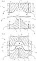
- Figs. 1 and 2 show a molding tool 1 for forming preforms from semi-finished fiber products 14.
- the molding tool 1 comprises a mold carrier (not shown) as well as an upper mold part 2 and a lower mold part 3.
- the mold tool 1 is designed so that the upper mold part 2 and lower mold part 3 open the Mold 1 away from each other ( Fig. 1 ) and to close the mold 1 towards each other ( Fig. 2 ) are movable.
- the inner contour profile of the upper mold part 4 and the inner contour profile of the lower mold part 5 are each designed so that one represents a negative of the other.
- the lower mold part 3 thus has an inner contour profile 5 in a transverse and / or longitudinal section, which rises steadily from the edge regions 5a up to a maximum elevation 5b in the center of the lower mold part 3.
- the upper mold part 2 has an inner contour profile 4 in a transverse and / or longitudinal section, which decreases steadily from the edge regions 4a to a depression 4b in the center of the upper mold part 2.
- it In a completely closed state of the molding tool 1, it has an intermediate space 15 between the upper mold part 2 and the lower mold part 3, which represents a negative of the workpiece to be manufactured.
- the molding tool 1 further comprises a first contour clamp 8 and a second contour clamp 9.
- the contour clamps 8, 9 are each designed like a sleeve, arranged concentrically with the upper mold part 2 and lower mold part 3 and each displaceable relative to them.
- the contour clamps 8, 9 each have a height l 1 , l 2 which corresponds to the height of the upper 2 and lower 3 of the mold.
- contour clamps that are not sleeve-like and are therefore not circumferential, or contour clamps with openings through which hot air can be injected.
- contour clamps 8, 9 have kinematics so that when the mold 1, the upper mold part 2 or the lower mold part 3 are closed, they advance up to a certain point, which is defined as a partially closed state within the scope of this invention, as shown in FIG Fig. 2 to see; In the event of a further closing that goes beyond the partially closed state, the contour clamps 8, 9 stand still, so that the upper mold part 2 or lower mold part 3 close with the contour clamps 8, 9.
- the contour clamps 8, 9 behave in the opposite way when the mold 1 is opened.
- contour clamps 8, 9 and the upper mold 2 or lower mold part 3 are designed so that they create a space 15 between the upper mold 2 and lower mold 3 in the partially closed state ( Fig. 2 ) seal.
- a sealed space is understood to mean that air can be injected into this space without it escaping immediately. Most of all, it will include understood that, for example, injecting hot air into a sealed room leads to a significant increase in the mean room temperature in this room.
- a valve can be designed within the scope of the invention, via which an air mass flow escaping from the space can be set.
- the molding tool 1 also has a gap 10 in the upper mold part 2 and a gap 11 in the lower mold part 3.
- the gaps 10, 11 run perpendicular, in the direction d 1 and d 2 , to the upper 12 and lower 13 outer wall of the mold 1, go through the entire upper mold part 2 and lower mold part 3 and are each centered in the upper mold part - 2 and lower mold part 3 arranged.
- a hot air heating device (not shown) is connected to the mold 1 in such a way that the hot air can be fed to the space 15 between the upper part 2 and the lower part 3 of the mold through the slots 10, 11.
- other configurations are also conceivable, for example a molding tool with more than one slot in the upper or lower part of the mold or slots which run obliquely to the outer walls.
- the mold 1 is in an open state ( Fig. 1 ) brought.
- the semi-finished fiber product 14 provided with a binder is placed in the opened mold 1 and the mold 1 is partially closed ( Fig. 2 ).
- the contour clamps 8, 9 run ahead of the upper mold part 2 or lower mold part 3, which means that the semi-finished fiber product 14 provided with a binder is fixed relative to the mold 1 by the contour clamps 8, 9.
- the contour clamps 8, 9 and the upper mold part 2 or lower mold part 3 seal an intermediate space 15 in the partially closed state.
- pre-deformation of the semifinished fiber product 14 occurs, as in FIG Fig. 2 illustrated.
- the hot air is generated by a hot air heating device (not shown) and fed through the slots 10, 11 in the direction d 1 and d 2 to the sealed space 15 between the upper 2 and lower 3 molds.
- the supply of hot air or the geometry of the space is designed in such a way that the semi-finished fiber product 14 provided with the binder is heated evenly and the binder is activated at the same time.
- the binder is not overheated, but only heated up to a temperature at which the binder is activated.
- the semifinished fiber product can be designed in such a way that it supports the distribution of heat due to its good thermal conductivity properties, e.g. through embedded carbon fibers.
- the hot air supply is switched off and the mold 1 is completely closed.
- the contour clamps 8, 9 are now stationary and only the upper mold part 2 or lower mold part 3 move around the semi-finished fiber product 14 in to bring its final state of deformation.
- the final deformation takes place around 1-2 seconds after activation of the binder.
- the molding tool 1 remains in the closed state until the preform is completely consolidated. At the end, the molding tool 1 is completely opened so that the preform is released by the contour clamps 8, 9 and can be removed from the molding tool 1.
Landscapes
- Engineering & Computer Science (AREA)
- Mechanical Engineering (AREA)
- Chemical & Material Sciences (AREA)
- Composite Materials (AREA)
- Reinforced Plastic Materials (AREA)
- Casting Or Compression Moulding Of Plastics Or The Like (AREA)
Description
- Die vorliegende Erfindung betrifft ein Verfahren sowie eine Vorrichtung zum Herstellen von Werkstücken, insbesondere Vorformlingen, aus Faserhalbzeugen.
- Der Anmelderin ist ein Verfahren zur Herstellung von Werkstücken, insbesondere Vorformlingen, aus Faserhalbzeugen bekannt, bei dem in einer ersten Bearbeitungsstation ein mit Binder versehenes Faserhalbzeug erwärmt wird, bevor dieses anschließend in eine zweite Bearbeitungsstation befördert wird, um es dort zu verformen. Dabei wird das mit Binder versehene Faserhalbzeug in der ersten Bearbeitungsstation auf eine Temperatur erwärmt, die über der Aktivierungstemperatur des Binders liegt, um so sicherzustellen, dass das Faserhalbzeug bei Ankunft in der zweiten Bearbeitungsstation nicht bereits unter die Aktivierungstemperatur des Binders abgekühlt ist.
- Dieses Verfahren besitzt den Nachteil, dass das mit Binder versehene Faserhalbzeug in der ersten Bearbeitungsstation überhitzt werden muss und ferner von der ersten zur zweiten Bearbeitungsstation befördert werden muss. Dies führt erstens zu einem energetisch ineffizienten Prozess (Überhitzung) und zweitens zu einer langen Fertigungszeit (Transport) und damit hohen Produktionskosten. Darüber hinaus ergeben sich aus dem Verfahren hohe Produktionssystemkosten auf Grund der hohen Anzahl von Bearbeitungsstationen und erforderlichen kostenintensiven, antihaft-beschichteten Transportwerkzeugen, die ein Verkleben der Transortwerkzeuge mit dem aktivierten Binder des Faserhalbzeugs verhindern.
- Ferner bezieht sich die
US 5 824 246 A auf ein Verfahren zum Ausbilden eines Binder-Verbundprodukts, bei dem eine mit Fasern angereicherte Bindemittelmasse mittels Heißluft aktiviert und anschließend mittels einer Verformungseinrichtung verformt wird. - Die
FR 2 542 666 A1 - Die
WO 2007/041782 A1 bezieht sich auf ein Verfahren und eine Vorrichtung, bei dem/der aufeinander geschichtete Halbzeuge mittels einer Verformungseinrichtung verformt werden, wobei eine Erwärmung der aufeinander geschichteten Halbzeuge durch Heizspulen, Heißluft oder Infrarotlicht erfolgt. - Darüber hinaus bezieht sich die
ES 2 116 839 A1 - Als weiteres Dokument ist die
US 2006/0012075 A1 bekannt, die ein Verfahren und eine Vorrichtung zum Ausbilden eines Innenverkleidungsteils zeigt. - Es ist daher Aufgabe der vorliegenden Erfindung ein Verfahren sowie eine Vorrichtung bereitzustellen, mit dem/der die Fertigungszeit zur Herstellung von Werkstücken, insbesondere Vorformlingen, aus Faserhalbzeugen auf eine energieeffiziente Art und Weise reduziert werden kann.
- Die Lösung der Aufgabe erfolgt durch das Verfahren des Patentanspruchs 1 sowie die Vorrichtung des Patentanspruchs 7. Bevorzugte Ausgestaltungen ergeben sich aus den jeweiligen Unteransprüchen.
- Der Erfindung liegt der Gedanke zugrunde, dass sich die Fertigungszeit eines Werkstücks aus den Transportzeiten zwischen verschiedenen Bearbeitungsstationen und den eigentlichen Bearbeitungszeiten auf den Bearbeitungsstationen zusammensetzt und das die Produktionssystemkosten maßgeblich durch die Anzahl von Bearbeitungsstationen bestimmt werden. Ein signifikanter Treiber zur Fertigungszeitminimierung stellt daher ein Verkürzen oder sogar Abschaffen von Transportzeiten dar; ein signifikanter Treiber zur Produktionssystemkostenminimierung stellt daher ferner eine Reduzierung der Anzahl von Bearbeitungsstationen dar. Dies führt zu dem Schluss, dass es vorteilhaft ist, mehrere Bearbeitungsstationen zusammenzufassen, um so in einer Bearbeitungsstation mehrere Bearbeitungsschritte auszuführen zu können. Auf der einen Seite werden damit die Fertigungszeiten reduziert, da Transportzeiten zwischen Bearbeitungsstationen wegfallen, und auf der anderen Seite resultiert daraus ein kostengünstigeres Produktionssystem, da die Anzahl von Bearbeitungsstation reduziert wird.
- Aus diesem Grund ist erfindungsgemäß vorgesehen, dass die Erwärmung des mit Binder versehenen Faserhalbzeugs und die Verformung des mit aktiviertem Binder versehenen Faserhalbzeugs in der gleichen Bearbeitungsstation stattfinden. Auf diese Weise entfällt die Transportzeit zwischen der Heizeinrichtung und der Verformungseinrichtung, was zu einer geringeren Fertigungsdauer und damit geringeren Fertigungskosten führt. Darüber hinaus ist kein Überhitzen des Faserhalbzeugs in der Heizeinrichtung erforderlich, da die Wärmeverluste während des Transports von Heizeinrichtung zu Verformeinrichtung umgangen werden. Ferner sind keine komplexen, kostenintensiven und antihaftbeschichteten Transportwerkzeuge notwendig, um das mit aktiviertem Binder versehene Halbzeug von der Heizeinrichtung zur Verformeinrichtung zu transportieren. Damit führt die Erfindung zu einer Reduktion von Fertigungszeit und Produktionskosten und darüber hinaus zu einer günstigeren Produktionseinrichtung. Ferner weißt das Formwerkzeug mindestens einen Konturspanner auf.
- Die Wärmezufuhr erfolgt dabei durch Heißluft. Dies führt zu dem Vorteil, dass so eine schnelle Erwärmung des Faserhalbzeugs ermöglicht wird, da die Heißluft mit einer hohen Relativgeschwindigkeit gegenüber dem Faserhalbzeugs in den Zwischenraum zwischen Formober- und Formunterteil eindüsbar ist. Dies führt zu hohen Nusselt-Zahlen und damit hohen Wärmeübertragungskoeffizienten zwischen Heißluft und Faserhalbzeug. Darüber hinaus ermöglicht diese bevorzugte Ausführungsform einen variothermen Erwärmungsprozess mit isothermen Werkzeugen, da die Wärmezufuhr nicht über die Werkzeuge erfolgt.
- Dabei erfolgt die Heißluftzuführung in den Zwischenraum zwischen Formober- und Formunterteil durch mindestens eine Öffnung in dem Konturspanner. Dies ist insofern vorteilhaft, als dass der Konturspanner somit einer weiteren Funktion, nämlich der Wärmezufuhr zu dem Zwischenraum zwischen Formober- und Formunterteil, dient. Dies spart mindestens ein Bauteil und führt somit zu einer weniger komplexen und kostengünstigeren Vorrichtung.
- Gemäß einer bevorzugten Ausführungsform findet die Verformung des mit aktivertem Binder versehenen Faserhalbzeugs durch das Schließen eines Formwerkzeugs, das ein Formober- und ein Formunterteil aufweist, statt. Das Formwerkzeug ist dabei so ausgestaltet, dass zum Schließen des Formwerkzeugs Formober- und Formunterteil aufeinander zu und zum Öffnen des Formwerkzeugs voneinander weg bewegbar sind. Im geschlossenen Zustand weist das Formwerkzeug dabei einen Zwischenraum auf, der ein Negativ von dem zu fertigenden Werkstück darstellt. Auf diese Weise wird eine Verformung eines Faserhalbzeugs auf einfache, kostengünstige Weise ermöglicht. Ferner ist das Fertigen von verschiedenen Werkstückformen insofern einfach, als dass lediglich Formober- bzw. Formunterteil des Formwerkzeugs ausgetauscht werden müssen, um eine neue Form herzustellen.
- Gemäß einer weiteren bevorzugten Ausführungsform kann das Schließen des Formwerkzeugs zwei Schritte aufweisen. In einem ersten Schritt wird das Formwerkzeug teilweise geschlossen, um es in einen teilweise geschlossenen Zustand zu bringen. In einem zweiten Schritt wird das Formwerkzeug vollständig geschlossen, um es in einen vollständig geschlossenen Zustand zu bringen. Dabei wird das Faserhalbzeug in einem ersten Schritt (teilweise geschlossener Zustand) relativ zum Formwerkzeug durch das Formwerkzeug fixiert, umso weitere Bearbeitungsschritte, z.B. Erwärmen, an dem Faserhalbzeug ausführen zu können. In einem zweiten Schritt wird das Formwerkzeug vollständig geschlossen, um das Faserhalbzeug zu verformen. Die Ausgestaltung des Formwerkzeugs in der bevorzugten Ausführungsform ermöglicht es somit, zwei Aufgaben mit einem Bauteil auszuführen, nämlich das Fixieren und das Verformen. Dies spart Kosten und verringert dabei die Komplexität und damit die Störanfälligkeit der Vorrichtung.
- Gemäß einer weiteren bevorzugten Ausführungsform wird beim teilweisen Schließen des Formwerkzeugs ein Zwischenraum zwischen Formober- und Formunterteil nach außen abgedichtet. Dies führt zu dem Vorteil, dass der Zwischenraum auf eine energetische effiziente Weise erwärmt werden kann, da ein Entweichen von erwärmter Luft durch die Dichtung unterbunden oder zumindest verringert wird.
- Gemäß einer weiteren besonders bevorzugten Ausführungsform erfolgt die Heißluftzuführung in den Zwischenraum zwischen Formober- und Formunterteil durch mindestens eine weitere Öffnung in dem Formwerkzeug. Dies ist insofern vorteilhaft, als dass das Formwerkzeug somit einer weiteren Funktion, nämlich der Wärmezufuhr zu dem Zwischenraum zwischen Formober- und Formunterteil, dient. Dies spart mindestens ein Bauteil und führt somit zu einer weniger komplexen und kostengünstigeren Vorrichtung.
- Gemäß einer weiteren besonders bevorzugten Ausführungsform wird der Binder während der Erwärmung nicht überhitzt. Dies führt zu dem Vorteil, dass somit ein energetisch effizienterer und damit kostengünstigerer Fertigungsprozess geschaffen wird.
- Gemäß einer weiteren besonders bevorzugten Ausführungsform wird das mit Binder versehene Faserhalbzeug gleichmäßig erwärmt. Dies führt zu einer gleichzeitigen Aktivierung des Binders und unterbindet damit ein lokales Überhitzen des Binders. Auch diese bevorzugte Ausführungsform führt damit zu einem energetisch effizienteren Bearbeitungsprozess.
- Gemäß der Erfindung weist die Vorrichtung, die die Merkmale des unabhängigen Anspruchs 7 umfasst, ferner mindestens einen Konturspanner auf, der mit dem Formober- oder Formunterteil verbunden ist, wobei der Konturspanner so ausgestaltet ist, dass er dem jeweiligen Formober- oder Formunterteil während des Schließens des Formwerkzeugs bis zu dem teilweise geschlossenen Zustand vorauseilt und bei einem weiteren Schließen bis zu dem vollständig geschlossenen Zustand stillsteht. Dies ermöglicht somit eine einfache und automatische Fixierung des Faserhalbzeugs durch den Konturspanner beim Schließen des Formwerkzeugs. Darüber hinaus stellt die Kinematik des Konturspanners sicher, dass das Faserhalbzeug beim vollständigen Schließen des Formwerkzeugs nicht beschädigt wird.
- Die erfindungsgemäße Vorrichtung kann einen ersten Konturspanner aufweisen, der mit dem Formunterteil verbunden ist, und einen zweiten Konturspanner aufweisen, der mit dem Formoberteil verbunden ist, wobei die Konturspanner jeweils hülsenförmig ausgestaltet sind und konzentrisch zu Formunter- bzw. Formoberteil angeordnet sind. Diese bevorzugte Ausgestaltung führt zu dem Vorteil, dass so eine umlaufende Fixierung des Faserhalbzeugs ermöglicht wird. Ferner ermöglicht sie eine einfache Dichtung des Zwischenraums zwischen Formunter- und Formoberteil.
- Gemäß einer weiteren besonders bevorzugten Ausführungsform der Erfindung weist die Vorrichtung mindestens jeweils eine Öffnung in Formober- und Formunterteil auf. Dies führt dazu, dass die Heißluft dem Faserhalbzeugs auf beiden Seiten zugeführt werden kann. Somit wird eine gleichmäßige Erwärmung des Faserhalbzeugs ermöglicht, was zu einem energetisch effizienteren Fertigungsprozess führt.
-
-
Fig. 1 zeigt eine Schnittdarstellung eines Formwerkzeugs zum Herstellen von Werkstücken, insbesondere Vorformlingen, aus Faserhalbzeugen in einem geöffneten Zustand. -
Fig. 2 zeigt eine Schnittdarstellung eines Formwerkzeugs zur Herstellung von Werkstücken, insbesondere Vorformlingen, aus Faserhalbzeugen in einem teilweise geschlossenen Zustand. - Eine bevorzugte Ausführungsform der vorliegenden Erfindung wird nachfolgend unter Bezugnahme auf die begleitenden Zeichnungen beschrieben. Weitere Varianten oder Modifikationen können jeweils miteinander kombiniert werden, um weitere Ausführungsformen auszubilden.
-
Fig. 1 und 2 zeigen ein Formwerkzeug 1 zum Bilden von Vorformlingen aus Faserhalbzeugen 14. Das Formwerkzeug 1 umfasst einen Formenträger (nicht gezeigt) sowie ein Formober- 2 und ein Formunterteil 3. Dabei ist das Formwerkzeug 1 so ausgebildet, dass Formober- 2 und Formunterteil 3 zum Öffnen des Formwerkzeugs 1 voneinander weg (Fig. 1 ) und zum Schließen des Formwerkzeugs 1 aufeinander zu (Fig. 2 ) bewegbar sind. - In der bevorzugten Ausführungsform ist der Innenkonturverlauf des Formoberteils 4 und der Innenkonturverlauf des Formunterteils 5 dabei jeweils so ausgestaltet, dass der eine jeweils ein Negativ des anderen darstellt. So weist das Formunterteil 3 einen Innenkonturverlauf 5 in einem Quer- und/oder Längsschnitt auf, der von den Randbereichen 5a stetig bis zu einer maximalen Erhebung 5b in der Mitte des Formunterteils 3 ansteigt. Im Gegensatz dazu weist das Formoberteil 2 einen Innenkonturverlauf 4 in einem Quer- und/oder Längsschnitt auf, der von den Randbereichen 4a stetig bis zu einer Vertiefung 4b in der Mitte des Formoberteils 2 sinkt. In einem vollständig geschlossenen Zustand des Formwerkzeugs 1 weist dieses einen Zwischenraum 15 zwischen Formober - 2 und Formunterteil 3 auf, der ein Negativ des zu fertigenden Werkstücks darstellt. Selbstverständlich sind hier auch andere Innenkonturverläufe der Formober 2- und Formunterteile 3 denkbar, so z.B. solche, bei denen der Innenkonturverlauf des Formoberteils 4 nicht ein Negativ des Innenkonturverlaufs des Formunterteils 5 darstellt, um so beispielsweise Vorformlinge mit variierender Dicke herstellen zu können.
- In der bevorzugten Ausführungsform umfasst das Formwerkzeug 1 ferner einen ersten Konturspanner 8 und einen zweiten Konturspanner 9. Die Konturspanner 8, 9 sind jeweils hülsenartig ausgestaltet, konzentrisch zu dem Formober- 2 bzw. Formunterteil 3 angeordnet und jeweils relativ zu diesen verschiebbar. Dabei weisen die Konturspanner 8, 9 jeweils eine Höhe l1, l2 auf, die der Höhe des Formober- 2 bzw. Formunterteils 3 entspricht. Auch hier sind weitere Ausführungsformen denkbar, so z.B. Konturspanner, die nicht hülsenartig ausgebildet und damit nicht umlaufend sind oder Konturspanner mit Öffnungen, durch die Heißluft eindüsbar ist.
- Ferner weisen die Konturspanner 8, 9 eine Kinematik auf, so dass sie beim Schließen des Formwerkzeugs 1, dem Formober- 2 bzw. Formunterteil 3 bis zu einem gewissen Punkt, der im Rahmen dieser Erfindung als teilweise geschlossener Zustand definiert ist, vorauseilen, wie in
Fig. 2 zu sehen; bei einem weiteren Schließen, das über den teilweise geschlossenen Zustand hinausgeht, stehen die Konturspanner 8, 9 hingegen still, sodass Formober- 2 bzw. Formunterteil 3 mit den Konturspanner 8, 9 aufschließen. Dem entgegengesetzt verhalten sich die Konturspanner 8, 9 beim Öffnen des Formwerkzeugs 1. So stehen diese bis zum Erreichen des teilweise geschlossenen Zustands still und Formober- 2 bzw. Formunterteil eilen den Konturspannern 8, 9 voraus; wird das Formwerkzeug 1 hingegen über den teilweise geschlossenen Zustand hinaus geöffnet, so schließen die Konturspanner 8, 9 mit dem Formober - 2 bzw. Formunterteil auf. - Darüber hinaus sind die Konturspanner 8, 9 und das Formober-2 bzw. Formunterteil 3 so ausgestaltet, dass sie einen Zwischenraum 15 zwischen Formober- 2 und Formunterteil 3 in dem teilweise geschlossen Zustand (
Fig. 2 ) abdichten. Unter einem abgedichteten Raum wird im Rahmen dieser Erfindung verstanden, dass in diesen Raum Luft eingedüst werden kann, ohne dass diese umgehend entweicht. Vor allem wird darunter verstanden, dass beispielsweise ein Eindüsen von Heißluft in einen abgedichteten Raum zu einem signifikanten Anstieg der mittleren Raumtemperatur in diesem Raum führt. - Um einen Wärme- bzw. Kältestau zu verhindern, bei dem die Heißluft nicht in das Faserhalbzeug eindringen kann, kann im Rahmen der Erfindung ein Ventil ausgebildet sein, über das sich ein aus dem Zwischenraum entweichender Luftmassenstrom einstellen lässt.
- Das Formwerkzeug 1 weist in der bevorzugten Ausführungsform weiter einen Spalt 10 in dem Formoberteil 2 und eine Spalt 11 in dem Formunterteil 3 auf. Die Spalte 10, 11 verlaufen dabei senkrecht, in Richtung d1 bzw. d2, zu der oberen 12 bzw. unteren 13 Außenwand des Formwerkzeugs 1, gehen durch das gesamte Formober- 2 bzw. Formunterteil 3 hindurch und sind dabei jeweils mittig in Formober- 2 und Formunterteil 3 angeordnet. Ferner ist eine Heißluft-Heizeinrichtung (nicht gezeigt) mit dem Formwerkzeug 1 so verbunden, dass die Heißluft dem Zwischenraum 15 zwischen Formober- 2 und Formunterteil 3 durch die Schlitze 10, 11 zuführbar ist. Selbstverständlich sind auch andere Ausgestaltungen denkbar, so z.B. ein Formwerkzeug mit mehr als einem Schlitz in Formober- bzw. Formunterteil oder Schlitzen die schräg zu den Außenwänden verlaufen.
- Im Folgenden wird ein bevorzugtes Verfahren zum Herstellen eines Vorformlings mit einem Formwerkzeug 1 der zuvor beschriebenen bevorzugten Vorrichtung beschrieben.
- In einem ersten Schritt wird das Formwerkzeug 1 in einen geöffneten Zustand (
Fig. 1 ) gebracht. - In einem zweiten Schritt wird das mit Binder versehene Faserhalbzeug 14 in das geöffnete Formwerkzeug 1 eingelegt und das Formwerkzeug 1 teilweise geschlossen (
Fig. 2 ). Beim teilweise Schließen des Formwerkzeugs 1 eilen die Konturspanner 8, 9 dem Formober- 2 bzw. Formunterteil 3 voraus, was dazu führt, dass das mit Binder versehene Faserhalbzeug 14 durch die Konturspanner 8, 9 relativ zum Formwerkzeug 1 fixiert wird. Die Konturspanner 8, 9 und das Formober- 2 bzw. Formunterteil 3 dichten dabei einen Zwischenraum 15 in dem teilweise geschlossenen Zustand ab. Darüber hinaus kommt es beim teilweisen Schließen des Formwerkzeugs 1 zu einer Vorverformung des Faserhalbzeugs 14, wie inFig. 2 illustriert. - Nunmehr wird das mit Binder versehene Faserhalbzeug 14, das durch die Konturspanner 8, 9 relativ zum Formwerkzeug 1 fixiert ist, durch Heißluft erwärmt. Die Heißluft wird dabei über eine Heißluft-Heizeinrichtung (nicht gezeigt) erzeugt und durch die Schlitze 10, 11 in Richtung d1 bzw. d2 dem abgedichteten Zwischenraum 15 zwischen Formober- 2 und Formunterteil 3 zugeführt.
- Die Zufuhr der Heißluft bzw. die Geometrie des Zwischenraums ist dabei so ausgestaltet, dass es zu einer gleichmäßigen Erwärmung des mit Binder versehenden Faserhalbzeugs 14 und damit zu einem gleichzeitigen Aktivieren des Binders kommt. Dabei wird der Binder nicht überhitzt, sondern nur bis auf eine Temperatur erwärmt, bei der eine Aktivierung des Binders stattfindet. Dabei kann das Faserhalbzeug so ausgebildet sein, dass es die Wärmeverteilung auf Grund guter Wärmeleitfähigkeitseigenschaften unterstützt, z.B. durch eingelagerte Kohlefasern.
- Schließlich wird die Heißluftzufuhr abgestellt, und das Formwerkzeug 1 vollständig geschlossen. Wir zuvor beschrieben stehen die Konturspanner 8, 9 nun still und nur Formober- 2 bzw. Formunterteil 3 bewegen sich, um das Faserhalbzeug 14 in seinen endgültigen Verformungszustand zu bringen. Die endgültige Verformung findet dabei rund 1-2 Sekunden nach der Aktivierung des Binders statt.
- Abschließend bleibt das Formwerkzeug 1 solange im geschlossenen Zustand, bis der Vorformling vollständig konsolidiert ist. Am Ende wird das Formwerkzeugs 1 vollständig geöffnet, sodass der Vorformling durch die Konturspanner 8, 9 freigegeben wird und aus dem Formwerkzeug 1 herausnehmbar ist.
- Auch hier sind andere Ausführungsformen denkbar, so z.B., dass die Heißluftzufuhr und das vollständige Verformen des Faserhalbzeugs 14 nicht sequentiell, sondern gleichzeitig stattfinden oder dass es zu keiner Vorverformung des Faserhalbzeugs 14 in dem teilweise geschlossenen Zustand kommt.
Claims (12)
- Verfahren zur Herstellung von Werkstücken, vorzugsweise Vorformlingen, aus Faserhalbzeugen (14), wobei das Verfahren die Schritte aufweist:Bereitstellen eines mit Binder versehenen Faserhalbzeugs (14),Wärmezufuhr zu dem mit Binder versehenen Faserhalbzeug (14) um den Binder zu aktivieren;Verformen des mit Binder versehenen Faserhalbzeugs (14),wobeidie Wärmezufuhr zu dem mit Binder versehenen Faserhalbzeug (14) und die Verformung des mit Binder versehenen Faserhalbzeugs (14) in derselben Bearbeitungsstation stattfinden,wobei das Formwerkzeug (1) mindestens einen Konturspanner (8, 9) aufweist,dadurch gekennzeichnet, dassdie Wärmezufuhr zu dem mit Binder versehenen Faserhalbzeug (14) durch Heißluft erfolgt,wobei die Heißluft durch mindestens eine Öffnung (10, 11) in dem Konturspanner (8, 9) einem Zwischenraum (15) zwischen Formober- (2) und Formunterteil (3) zugeführt wird.
- Verfahren nach Anspruch 1, dadurch gekennzeichnet, dass das mit Binder versehene Faserhalbzeug (14) durch das Schließen eines Formwerkzeugs (1), das ein Formober-(2) und ein Formunterteil (3) aufweist, verformt wird.
- Verfahren nach Anspruch 2, dadurch gekennzeichnet, dass das Schließen des Formwerkzeugs (1) zwei Schritte aufweist, wobei in einem ersten Schritt das Formwerkzeug (1) teilweise geschlossen wird, um es in einen teilweise geschlossenen Zustand zu bringen, und in einem zweiten Schritt das Formwerkzeug (1) vollständig geschlossen wird, um es in einen vollständig geschlossenen Zustand zu bringen.
- Verfahren nach Anspruch 3, dadurch gekennzeichnet, dass beim teilweisen Schließen des Formwerkzeugs (1) ein Zwischenraum (15) zwischen Formober- (2) und Formunterteil (3) des Formwerkzeugs (1) nach außen abgedichtet wird.
- Verfahren nach einem der vorangegangenen Ansprüche, dadurch gekennzeichnet, dass die Heißluft durch mindestens eine Öffnung (10, 11) in dem Formwerkzeug (1) einem Zwischenraum (15) zwischen Formober- (2) und Formunterteil (3) zugeführt wird.
- Verfahren nach einem der vorhergehenden Ansprüche, dadurch gekennzeichnet, dass das Faserhalbzeug (14) in einem ersten Schritt vorverformt wird, in einem zweiten Schritt erwärmt wird und in einem dritten Schritt verformt wird.
- Vorrichtung zur Durchführung des Verfahrens nach einem der vorhergehenden Ansprüche, aufweisend:eine Wärmequelle zum Aktivieren des Binders eines mit Binder versehenen Faserhalbzeugs (14);ein Formwerkzeug (1) zur Wärmezufuhr zu dem mit Binder versehenen Faserhalbzeug und zum Verformen des mit Binder versehenen Faserhalbzeug (14),wobei das Formwerkzeug (1) mindestens einen Konturspanner (8, 9) aufweist, der mit dem Formober- (2) oder dem Formunterteil (3) verbunden ist, wobei der Konturspanner (8, 9) so ausgestaltet ist, dass er dem jeweiligen Formober-(2) oder Formunterteil (3) während des Schließens des Formwerkzeugs (1) bis zu dem teilweise geschlossen Zustand vorauseilt und bei einem weiteren Schließen bis zu dem vollständig geschlossenen Zustand stillsteht,wobeider Konturspanner (8, 9) mindestens eine Öffnung (10, 11) aufweist, durch die Heißluft in den Zwischenraum (15) zwischen Formober- (2) und Formunterteil (3) eindüsbar ist.
- Vorrichtung nach Anspruch 7, dadurch gekennzeichnet, dass das Formwerkzeug (1) einen Formober- (2) und einen Formunterteil (3) aufweist, die zum Öffnen des Formwerkzeugs (1) voneinander weg und zum Schließen des Formwerkzeugs (1) aufeinander zu bewegbar sind.
- Vorrichtung nach Anspruch 7 und/oder 8, dadurch gekennzeichnet, dass das Formwerkzeug (1) in einem teilweise geschlossen Zustand einen Zwischenraum (15) zwischen Formober- (2) und Formunterteil (3) aufweist, der nach außen abgedichtet ist.
- Vorrichtung nach einem der Ansprüche 7-9, dadurch gekennzeichnet, dass die Vorrichtung einen ersten Konturspanner (8) aufweist, der mit dem Formunterteil (2) verbunden ist, und einen zweiten Konturspanner (9) aufweist, der mit dem Formoberteil (3) verbunden ist, wobei die Konturspanner jeweils hülsenförmig ausgestaltet sind und konzentrisch zu Formunter- (2) bzw. Formoberteil (3) angeordnet sind.
- Vorrichtung nach einem der Ansprüche 7-10, dadurch gekennzeichnet, dass das Formwerkzeug (1) mindestens eine Öffnung (10, 11) aufweist, durch die Heißluft in den Zwischenraum (15) zwischen Formober- (2) und Formunterteil (3) eindüsbar ist.
- Vorrichtung nach Anspruch 10, dadurch gekennzeichnet, dass Formober- (2) und Formunterteil (3) und/oder erster (8) und zweiter Konturspanner (9) jeweils mindestens eine Öffnung aufweisen, durch die Heißluft in einen Zwischenraum (15) eindüsbar ist.
Priority Applications (1)
| Application Number | Priority Date | Filing Date | Title |
|---|---|---|---|
| PL13196019T PL2746019T3 (pl) | 2012-12-24 | 2013-12-06 | Sposób i urządzenie do wytwarzania przedmiotów obrabianych z półwyrobów włóknistych |
Applications Claiming Priority (1)
| Application Number | Priority Date | Filing Date | Title |
|---|---|---|---|
| DE102012224357.7A DE102012224357A1 (de) | 2012-12-24 | 2012-12-24 | Verfahren und Vorrichtung zum Herstellen von Werkstücken aus Faserhalbzeugen |
Publications (2)
| Publication Number | Publication Date |
|---|---|
| EP2746019A1 EP2746019A1 (de) | 2014-06-25 |
| EP2746019B1 true EP2746019B1 (de) | 2021-01-20 |
Family
ID=49766889
Family Applications (1)
| Application Number | Title | Priority Date | Filing Date |
|---|---|---|---|
| EP13196019.7A Active EP2746019B1 (de) | 2012-12-24 | 2013-12-06 | Verfahren und Vorrichtung zum Herstellen von Werkstücken aus Faserhalbzeugen |
Country Status (6)
| Country | Link |
|---|---|
| EP (1) | EP2746019B1 (de) |
| DE (1) | DE102012224357A1 (de) |
| ES (1) | ES2866724T3 (de) |
| HU (1) | HUE053933T2 (de) |
| PL (1) | PL2746019T3 (de) |
| PT (1) | PT2746019T (de) |
Citations (1)
| Publication number | Priority date | Publication date | Assignee | Title |
|---|---|---|---|---|
| US20060012075A1 (en) * | 2004-07-19 | 2006-01-19 | R + S Technik Gmbh | Method and apparatus for molding a laminated trim component without use of slip frame |
Family Cites Families (11)
| Publication number | Priority date | Publication date | Assignee | Title |
|---|---|---|---|---|
| FR2542666B1 (fr) * | 1983-03-17 | 1986-06-20 | Saint Gobain Isover | Panneaux composites moules |
| US5139407A (en) * | 1989-09-01 | 1992-08-18 | General Electric Company | Apparatus for reducing thermoplastic material compression mold cycle time |
| DE4017978C2 (de) * | 1990-06-05 | 1993-09-30 | Dornier Luftfahrt | Herstellung profilierter Stringer |
| US5824246A (en) * | 1991-03-29 | 1998-10-20 | Engineered Composites | Method of forming a thermoactive binder composite |
| ES2116839B1 (es) * | 1994-05-18 | 1999-03-01 | Aguilar Angel Garcia | Procedimiento y equipo para la fabricacion de piezas de gran espesor termoconformadas a partir de material fibroso textil. |
| DE19809264C2 (de) * | 1998-03-04 | 2003-06-26 | Eldra Kunststofftechnik Gmbh | Fasergelegeanordnung und Verfahren zur Herstellung eines Vorformlings |
| WO2007041782A1 (en) * | 2005-10-11 | 2007-04-19 | Crc For Advanced Composite Structures Limited | A method of binding dry reinforcement fibres |
| US8333858B2 (en) * | 2006-02-02 | 2012-12-18 | The Boeing Company | Method for fabricating curved thermoplastic composite parts |
| US8771823B2 (en) * | 2006-07-14 | 2014-07-08 | Huchinson Aéronautique & Industrie Limitée | Thermoplastic part, tool and method for the manufacturing thereof |
| DE102007058727A1 (de) * | 2007-12-06 | 2009-06-10 | Airbus Deutschland Gmbh | Verfahren zur Herstellung eines FVW-Vorformlings aus einem Laminat mit zumindest zwei Prepreg-Lagen sowie Herstellungsvorrichtung für ein derartiges Verfahren |
| DE102008011411A1 (de) * | 2008-02-27 | 2009-09-10 | Airbus Deutschland Gmbh | Verformungs-Vorrichtung zur Herstellung profilierter Halbzeuge, Anlage mit einer solchen Verformungs-Vorrichtung und Verfahren zur Herstellung profilierter Halbzeuge |
-
2012
- 2012-12-24 DE DE102012224357.7A patent/DE102012224357A1/de not_active Withdrawn
-
2013
- 2013-12-06 PL PL13196019T patent/PL2746019T3/pl unknown
- 2013-12-06 PT PT131960197T patent/PT2746019T/pt unknown
- 2013-12-06 ES ES13196019T patent/ES2866724T3/es active Active
- 2013-12-06 HU HUE13196019A patent/HUE053933T2/hu unknown
- 2013-12-06 EP EP13196019.7A patent/EP2746019B1/de active Active
Patent Citations (1)
| Publication number | Priority date | Publication date | Assignee | Title |
|---|---|---|---|---|
| US20060012075A1 (en) * | 2004-07-19 | 2006-01-19 | R + S Technik Gmbh | Method and apparatus for molding a laminated trim component without use of slip frame |
Also Published As
| Publication number | Publication date |
|---|---|
| PL2746019T3 (pl) | 2021-09-20 |
| ES2866724T3 (es) | 2021-10-19 |
| EP2746019A1 (de) | 2014-06-25 |
| PT2746019T (pt) | 2021-04-22 |
| DE102012224357A1 (de) | 2014-07-10 |
| HUE053933T2 (hu) | 2021-07-28 |
Similar Documents
| Publication | Publication Date | Title |
|---|---|---|
| DE102009060689B4 (de) | Verfahren zur Herstellung eines faserverstärkten Bauteils sowie Vorrichtung zur Durchführung des Verfahrens | |
| EP2988913B1 (de) | Werkzeug zur herstellung eines verbundstoff-bauteils mit wenigstens einer entlüftungsbohrung und darin angeordnetem auswerferstift | |
| EP2585276B1 (de) | Verfahren und vorrichtung zur herstellung eines bauteils mittels spritzgiessens und heissgasschweissens | |
| DD139813A5 (de) | Form,insbesondere spritzgiessform,zum herstellen von fo | |
| DE102011012500A1 (de) | Vorrichtung und Verfahren zum Herstellen eines Faserverbundwerkstückes | |
| DE102014109174A1 (de) | Verfahren zum Herstellen eines Formkörpers aus einem Fasermaterial sowie eine Vorrichtung zum Durchführen des Verfahrens | |
| DE102012010469B4 (de) | Verfahren zur Herstellung von faserverstärkten Bauteilen | |
| EP2483049B1 (de) | Imd-form, spritzgussvorrichtung mit einer solchen imd-form sowie verfahren zur herstellung eines foliendekorierten kunststoffteils | |
| DE4236439A1 (de) | Verfahren und Vorrichtung zum Herstellen von Hohlkörpern aus thermoplastischem Kunststoff | |
| EP2658703B1 (de) | Verfahren und vorrichtung zur herstellung eines bauteils mittels spritzgiessens und schweissens | |
| EP3036090B1 (de) | Werkzeugsystem und verfahren zur herstellung von bauteilen nach dem rtm-verfahren | |
| DE112015006020T5 (de) | Formwerkzeuge und Verfahren zum Formpressen einer Kunststoffplatte | |
| DE102011110206A1 (de) | Formwerkzeug | |
| EP0413714A1 (de) | Verfahren und anlage zur grossseriellen verarbeitung von hochleistungs-faserverbundwerkstoffen | |
| DE3138858C2 (de) | Verfahren zur Herstellung von Fertigformlingen unterschiedlichen Querschnitts aus thermoplastischem Werkstoff | |
| EP3790729A1 (de) | Vorrichtung und verfahren zum kontinuierlichen blasformen faserverstärkter thermoplastischer hohlprofile mit einem konstanten oder sich änderndem querschnitt | |
| DE102018203704A1 (de) | Verfahren zum Herstellen eines Bauteils und Vorrichtung zum Herstellen eines Bauteils | |
| DE102012224357A1 (de) | Verfahren und Vorrichtung zum Herstellen von Werkstücken aus Faserhalbzeugen | |
| EP1960180A1 (de) | Nachbehandlungsverfahren sowie vorrichtung hierfür | |
| DE102015201264A1 (de) | Verformvorrichtung zum Verformen eines vorimprägnierten Faserverbundhalbzeuges sowie Verfahren zum Verformen eines vorimprägnierten Faserverbundhalbzeuges | |
| EP4469259B1 (de) | Verfahren und vorrichtung zum aufweiten von tubenrohlingen | |
| EP3224014B1 (de) | Verfahren zur herstellung eines spritzgussbauteils mit einem aus einem organoblech bestehenden einleger und vorrichtung zur durchführung des verfahrens | |
| DE102011050976A1 (de) | Auswerfvorrichtung und Werkzeug mit einer derartigen Auswerfvorrichtung | |
| DE2262871C3 (de) | Verfahren und Vorrichtung zum Herstellen eines zweischichtigen Hohlkörpers nach dem Spritzblasverfahren | |
| DE102006046305A1 (de) | Vorrichtung und Verfahren zum mindestens partiellen Umformen von Blech über die bekannten Formgebungsgrenzen hinaus |
Legal Events
| Date | Code | Title | Description |
|---|---|---|---|
| PUAI | Public reference made under article 153(3) epc to a published international application that has entered the european phase |
Free format text: ORIGINAL CODE: 0009012 |
|
| 17P | Request for examination filed |
Effective date: 20131206 |
|
| AK | Designated contracting states |
Kind code of ref document: A1 Designated state(s): AL AT BE BG CH CY CZ DE DK EE ES FI FR GB GR HR HU IE IS IT LI LT LU LV MC MK MT NL NO PL PT RO RS SE SI SK SM TR |
|
| AX | Request for extension of the european patent |
Extension state: BA ME |
|
| R17P | Request for examination filed (corrected) |
Effective date: 20141017 |
|
| RBV | Designated contracting states (corrected) |
Designated state(s): AL AT BE BG CH CY CZ DE DK EE ES FI FR GB GR HR HU IE IS IT LI LT LU LV MC MK MT NL NO PL PT RO RS SE SI SK SM TR |
|
| STAA | Information on the status of an ep patent application or granted ep patent |
Free format text: STATUS: EXAMINATION IS IN PROGRESS |
|
| 17Q | First examination report despatched |
Effective date: 20180618 |
|
| GRAP | Despatch of communication of intention to grant a patent |
Free format text: ORIGINAL CODE: EPIDOSNIGR1 |
|
| STAA | Information on the status of an ep patent application or granted ep patent |
Free format text: STATUS: GRANT OF PATENT IS INTENDED |
|
| RIC1 | Information provided on ipc code assigned before grant |
Ipc: B29C 51/42 20060101ALI20200526BHEP Ipc: B29C 70/56 20060101ALI20200526BHEP Ipc: B29C 51/26 20060101ALI20200526BHEP Ipc: B29C 35/04 20060101ALN20200526BHEP Ipc: B29C 33/04 20060101ALI20200526BHEP Ipc: B29C 70/46 20060101ALI20200526BHEP Ipc: B29B 11/16 20060101AFI20200526BHEP |
|
| INTG | Intention to grant announced |
Effective date: 20200616 |
|
| GRAJ | Information related to disapproval of communication of intention to grant by the applicant or resumption of examination proceedings by the epo deleted |
Free format text: ORIGINAL CODE: EPIDOSDIGR1 |
|
| STAA | Information on the status of an ep patent application or granted ep patent |
Free format text: STATUS: EXAMINATION IS IN PROGRESS |
|
| GRAR | Information related to intention to grant a patent recorded |
Free format text: ORIGINAL CODE: EPIDOSNIGR71 |
|
| GRAS | Grant fee paid |
Free format text: ORIGINAL CODE: EPIDOSNIGR3 |
|
| STAA | Information on the status of an ep patent application or granted ep patent |
Free format text: STATUS: GRANT OF PATENT IS INTENDED |
|
| INTC | Intention to grant announced (deleted) | ||
| RIC1 | Information provided on ipc code assigned before grant |
Ipc: B29C 70/56 20060101ALI20201014BHEP Ipc: B29B 11/16 20060101AFI20201014BHEP Ipc: B29C 33/04 20060101ALI20201014BHEP Ipc: B29C 70/46 20060101ALI20201014BHEP Ipc: B29C 51/26 20060101ALI20201014BHEP Ipc: B29C 35/04 20060101ALN20201014BHEP Ipc: B29C 51/42 20060101ALI20201014BHEP |
|
| INTG | Intention to grant announced |
Effective date: 20201028 |
|
| GRAA | (expected) grant |
Free format text: ORIGINAL CODE: 0009210 |
|
| STAA | Information on the status of an ep patent application or granted ep patent |
Free format text: STATUS: THE PATENT HAS BEEN GRANTED |
|
| AK | Designated contracting states |
Kind code of ref document: B1 Designated state(s): AL AT BE BG CH CY CZ DE DK EE ES FI FR GB GR HR HU IE IS IT LI LT LU LV MC MK MT NL NO PL PT RO RS SE SI SK SM TR |
|
| REG | Reference to a national code |
Ref country code: GB Ref legal event code: FG4D Free format text: NOT ENGLISH |
|
| REG | Reference to a national code |
Ref country code: CH Ref legal event code: EP |
|
| REG | Reference to a national code |
Ref country code: DE Ref legal event code: R096 Ref document number: 502013015447 Country of ref document: DE |
|
| REG | Reference to a national code |
Ref country code: AT Ref legal event code: REF Ref document number: 1355991 Country of ref document: AT Kind code of ref document: T Effective date: 20210215 |
|
| REG | Reference to a national code |
Ref country code: IE Ref legal event code: FG4D Free format text: LANGUAGE OF EP DOCUMENT: GERMAN |
|
| REG | Reference to a national code |
Ref country code: PT Ref legal event code: SC4A Ref document number: 2746019 Country of ref document: PT Date of ref document: 20210422 Kind code of ref document: T Free format text: AVAILABILITY OF NATIONAL TRANSLATION Effective date: 20210416 |
|
| REG | Reference to a national code |
Ref country code: CH Ref legal event code: NV Representative=s name: VALIPAT S.A. C/O BOVARD SA NEUCHATEL, CH |
|
| REG | Reference to a national code |
Ref country code: SK Ref legal event code: T3 Ref document number: E 37170 Country of ref document: SK Ref country code: NL Ref legal event code: MP Effective date: 20210120 |
|
| REG | Reference to a national code |
Ref country code: LT Ref legal event code: MG9D |
|
| REG | Reference to a national code |
Ref country code: HU Ref legal event code: AG4A Ref document number: E053933 Country of ref document: HU |
|
| PG25 | Lapsed in a contracting state [announced via postgrant information from national office to epo] |
Ref country code: HR Free format text: LAPSE BECAUSE OF FAILURE TO SUBMIT A TRANSLATION OF THE DESCRIPTION OR TO PAY THE FEE WITHIN THE PRESCRIBED TIME-LIMIT Effective date: 20210120 Ref country code: FI Free format text: LAPSE BECAUSE OF FAILURE TO SUBMIT A TRANSLATION OF THE DESCRIPTION OR TO PAY THE FEE WITHIN THE PRESCRIBED TIME-LIMIT Effective date: 20210120 Ref country code: GR Free format text: LAPSE BECAUSE OF FAILURE TO SUBMIT A TRANSLATION OF THE DESCRIPTION OR TO PAY THE FEE WITHIN THE PRESCRIBED TIME-LIMIT Effective date: 20210421 Ref country code: LT Free format text: LAPSE BECAUSE OF FAILURE TO SUBMIT A TRANSLATION OF THE DESCRIPTION OR TO PAY THE FEE WITHIN THE PRESCRIBED TIME-LIMIT Effective date: 20210120 Ref country code: BG Free format text: LAPSE BECAUSE OF FAILURE TO SUBMIT A TRANSLATION OF THE DESCRIPTION OR TO PAY THE FEE WITHIN THE PRESCRIBED TIME-LIMIT Effective date: 20210420 Ref country code: NO Free format text: LAPSE BECAUSE OF FAILURE TO SUBMIT A TRANSLATION OF THE DESCRIPTION OR TO PAY THE FEE WITHIN THE PRESCRIBED TIME-LIMIT Effective date: 20210420 Ref country code: NL Free format text: LAPSE BECAUSE OF FAILURE TO SUBMIT A TRANSLATION OF THE DESCRIPTION OR TO PAY THE FEE WITHIN THE PRESCRIBED TIME-LIMIT Effective date: 20210120 |
|
| PG25 | Lapsed in a contracting state [announced via postgrant information from national office to epo] |
Ref country code: RS Free format text: LAPSE BECAUSE OF FAILURE TO SUBMIT A TRANSLATION OF THE DESCRIPTION OR TO PAY THE FEE WITHIN THE PRESCRIBED TIME-LIMIT Effective date: 20210120 Ref country code: LV Free format text: LAPSE BECAUSE OF FAILURE TO SUBMIT A TRANSLATION OF THE DESCRIPTION OR TO PAY THE FEE WITHIN THE PRESCRIBED TIME-LIMIT Effective date: 20210120 Ref country code: SE Free format text: LAPSE BECAUSE OF FAILURE TO SUBMIT A TRANSLATION OF THE DESCRIPTION OR TO PAY THE FEE WITHIN THE PRESCRIBED TIME-LIMIT Effective date: 20210120 |
|
| PG25 | Lapsed in a contracting state [announced via postgrant information from national office to epo] |
Ref country code: IS Free format text: LAPSE BECAUSE OF FAILURE TO SUBMIT A TRANSLATION OF THE DESCRIPTION OR TO PAY THE FEE WITHIN THE PRESCRIBED TIME-LIMIT Effective date: 20210520 |
|
| REG | Reference to a national code |
Ref country code: ES Ref legal event code: FG2A Ref document number: 2866724 Country of ref document: ES Kind code of ref document: T3 Effective date: 20211019 |
|
| REG | Reference to a national code |
Ref country code: DE Ref legal event code: R097 Ref document number: 502013015447 Country of ref document: DE |
|
| PG25 | Lapsed in a contracting state [announced via postgrant information from national office to epo] |
Ref country code: SM Free format text: LAPSE BECAUSE OF FAILURE TO SUBMIT A TRANSLATION OF THE DESCRIPTION OR TO PAY THE FEE WITHIN THE PRESCRIBED TIME-LIMIT Effective date: 20210120 Ref country code: EE Free format text: LAPSE BECAUSE OF FAILURE TO SUBMIT A TRANSLATION OF THE DESCRIPTION OR TO PAY THE FEE WITHIN THE PRESCRIBED TIME-LIMIT Effective date: 20210120 |
|
| PLBE | No opposition filed within time limit |
Free format text: ORIGINAL CODE: 0009261 |
|
| STAA | Information on the status of an ep patent application or granted ep patent |
Free format text: STATUS: NO OPPOSITION FILED WITHIN TIME LIMIT |
|
| PG25 | Lapsed in a contracting state [announced via postgrant information from national office to epo] |
Ref country code: RO Free format text: LAPSE BECAUSE OF FAILURE TO SUBMIT A TRANSLATION OF THE DESCRIPTION OR TO PAY THE FEE WITHIN THE PRESCRIBED TIME-LIMIT Effective date: 20210120 Ref country code: DK Free format text: LAPSE BECAUSE OF FAILURE TO SUBMIT A TRANSLATION OF THE DESCRIPTION OR TO PAY THE FEE WITHIN THE PRESCRIBED TIME-LIMIT Effective date: 20210120 |
|
| 26N | No opposition filed |
Effective date: 20211021 |
|
| PG25 | Lapsed in a contracting state [announced via postgrant information from national office to epo] |
Ref country code: AL Free format text: LAPSE BECAUSE OF FAILURE TO SUBMIT A TRANSLATION OF THE DESCRIPTION OR TO PAY THE FEE WITHIN THE PRESCRIBED TIME-LIMIT Effective date: 20210120 |
|
| PG25 | Lapsed in a contracting state [announced via postgrant information from national office to epo] |
Ref country code: SI Free format text: LAPSE BECAUSE OF FAILURE TO SUBMIT A TRANSLATION OF THE DESCRIPTION OR TO PAY THE FEE WITHIN THE PRESCRIBED TIME-LIMIT Effective date: 20210120 |
|
| PG25 | Lapsed in a contracting state [announced via postgrant information from national office to epo] |
Ref country code: IS Free format text: LAPSE BECAUSE OF FAILURE TO SUBMIT A TRANSLATION OF THE DESCRIPTION OR TO PAY THE FEE WITHIN THE PRESCRIBED TIME-LIMIT Effective date: 20210520 |
|
| PG25 | Lapsed in a contracting state [announced via postgrant information from national office to epo] |
Ref country code: MC Free format text: LAPSE BECAUSE OF FAILURE TO SUBMIT A TRANSLATION OF THE DESCRIPTION OR TO PAY THE FEE WITHIN THE PRESCRIBED TIME-LIMIT Effective date: 20210120 |
|
| REG | Reference to a national code |
Ref country code: BE Ref legal event code: MM Effective date: 20211231 |
|
| PG25 | Lapsed in a contracting state [announced via postgrant information from national office to epo] |
Ref country code: LU Free format text: LAPSE BECAUSE OF NON-PAYMENT OF DUE FEES Effective date: 20211206 Ref country code: IE Free format text: LAPSE BECAUSE OF NON-PAYMENT OF DUE FEES Effective date: 20211206 |
|
| PG25 | Lapsed in a contracting state [announced via postgrant information from national office to epo] |
Ref country code: BE Free format text: LAPSE BECAUSE OF NON-PAYMENT OF DUE FEES Effective date: 20211231 |
|
| PGFP | Annual fee paid to national office [announced via postgrant information from national office to epo] |
Ref country code: SK Payment date: 20221122 Year of fee payment: 10 Ref country code: PT Payment date: 20221117 Year of fee payment: 10 Ref country code: GB Payment date: 20221214 Year of fee payment: 10 Ref country code: FR Payment date: 20221214 Year of fee payment: 10 Ref country code: DE Payment date: 20220615 Year of fee payment: 10 Ref country code: CZ Payment date: 20221125 Year of fee payment: 10 Ref country code: AT Payment date: 20221216 Year of fee payment: 10 |
|
| PGFP | Annual fee paid to national office [announced via postgrant information from national office to epo] |
Ref country code: PL Payment date: 20221201 Year of fee payment: 10 Ref country code: HU Payment date: 20221218 Year of fee payment: 10 |
|
| PGFP | Annual fee paid to national office [announced via postgrant information from national office to epo] |
Ref country code: ES Payment date: 20230102 Year of fee payment: 10 Ref country code: CH Payment date: 20221212 Year of fee payment: 10 |
|
| PGFP | Annual fee paid to national office [announced via postgrant information from national office to epo] |
Ref country code: IT Payment date: 20221215 Year of fee payment: 10 |
|
| P01 | Opt-out of the competence of the unified patent court (upc) registered |
Effective date: 20230523 |
|
| PG25 | Lapsed in a contracting state [announced via postgrant information from national office to epo] |
Ref country code: CY Free format text: LAPSE BECAUSE OF FAILURE TO SUBMIT A TRANSLATION OF THE DESCRIPTION OR TO PAY THE FEE WITHIN THE PRESCRIBED TIME-LIMIT Effective date: 20210120 |
|
| PG25 | Lapsed in a contracting state [announced via postgrant information from national office to epo] |
Ref country code: MK Free format text: LAPSE BECAUSE OF FAILURE TO SUBMIT A TRANSLATION OF THE DESCRIPTION OR TO PAY THE FEE WITHIN THE PRESCRIBED TIME-LIMIT Effective date: 20210120 |
|
| PG25 | Lapsed in a contracting state [announced via postgrant information from national office to epo] |
Ref country code: TR Free format text: LAPSE BECAUSE OF FAILURE TO SUBMIT A TRANSLATION OF THE DESCRIPTION OR TO PAY THE FEE WITHIN THE PRESCRIBED TIME-LIMIT Effective date: 20210120 |
|
| REG | Reference to a national code |
Ref country code: DE Ref legal event code: R119 Ref document number: 502013015447 Country of ref document: DE |
|
| PG25 | Lapsed in a contracting state [announced via postgrant information from national office to epo] |
Ref country code: CZ Free format text: LAPSE BECAUSE OF NON-PAYMENT OF DUE FEES Effective date: 20231206 |
|
| REG | Reference to a national code |
Ref country code: SK Ref legal event code: MM4A Ref document number: E 37170 Country of ref document: SK Effective date: 20231206 |
|
| PG25 | Lapsed in a contracting state [announced via postgrant information from national office to epo] |
Ref country code: CZ Free format text: LAPSE BECAUSE OF NON-PAYMENT OF DUE FEES Effective date: 20231206 |
|
| REG | Reference to a national code |
Ref country code: CH Ref legal event code: PL |
|
| PG25 | Lapsed in a contracting state [announced via postgrant information from national office to epo] |
Ref country code: PT Free format text: LAPSE BECAUSE OF NON-PAYMENT OF DUE FEES Effective date: 20240606 |
|
| REG | Reference to a national code |
Ref country code: AT Ref legal event code: MM01 Ref document number: 1355991 Country of ref document: AT Kind code of ref document: T Effective date: 20231206 |
|
| GBPC | Gb: european patent ceased through non-payment of renewal fee |
Effective date: 20231206 |
|
| PG25 | Lapsed in a contracting state [announced via postgrant information from national office to epo] |
Ref country code: PT Free format text: LAPSE BECAUSE OF NON-PAYMENT OF DUE FEES Effective date: 20240606 |
|
| PG25 | Lapsed in a contracting state [announced via postgrant information from national office to epo] |
Ref country code: MT Free format text: LAPSE BECAUSE OF FAILURE TO SUBMIT A TRANSLATION OF THE DESCRIPTION OR TO PAY THE FEE WITHIN THE PRESCRIBED TIME-LIMIT Effective date: 20210120 |
|
| PG25 | Lapsed in a contracting state [announced via postgrant information from national office to epo] |
Ref country code: DE Free format text: LAPSE BECAUSE OF NON-PAYMENT OF DUE FEES Effective date: 20240702 |
|
| PG25 | Lapsed in a contracting state [announced via postgrant information from national office to epo] |
Ref country code: GB Free format text: LAPSE BECAUSE OF NON-PAYMENT OF DUE FEES Effective date: 20231206 |
|
| PG25 | Lapsed in a contracting state [announced via postgrant information from national office to epo] |
Ref country code: FR Free format text: LAPSE BECAUSE OF NON-PAYMENT OF DUE FEES Effective date: 20231231 |
|
| PG25 | Lapsed in a contracting state [announced via postgrant information from national office to epo] |
Ref country code: CH Free format text: LAPSE BECAUSE OF NON-PAYMENT OF DUE FEES Effective date: 20231231 |
|
| PG25 | Lapsed in a contracting state [announced via postgrant information from national office to epo] |
Ref country code: AT Free format text: LAPSE BECAUSE OF NON-PAYMENT OF DUE FEES Effective date: 20231206 |
|
| PG25 | Lapsed in a contracting state [announced via postgrant information from national office to epo] |
Ref country code: SK Free format text: LAPSE BECAUSE OF NON-PAYMENT OF DUE FEES Effective date: 20231206 Ref country code: HU Free format text: LAPSE BECAUSE OF NON-PAYMENT OF DUE FEES Effective date: 20231207 |
|
| PG25 | Lapsed in a contracting state [announced via postgrant information from national office to epo] |
Ref country code: SK Free format text: LAPSE BECAUSE OF NON-PAYMENT OF DUE FEES Effective date: 20231206 Ref country code: HU Free format text: LAPSE BECAUSE OF NON-PAYMENT OF DUE FEES Effective date: 20231207 Ref country code: GB Free format text: LAPSE BECAUSE OF NON-PAYMENT OF DUE FEES Effective date: 20231206 Ref country code: FR Free format text: LAPSE BECAUSE OF NON-PAYMENT OF DUE FEES Effective date: 20231231 Ref country code: DE Free format text: LAPSE BECAUSE OF NON-PAYMENT OF DUE FEES Effective date: 20240702 Ref country code: CH Free format text: LAPSE BECAUSE OF NON-PAYMENT OF DUE FEES Effective date: 20231231 Ref country code: AT Free format text: LAPSE BECAUSE OF NON-PAYMENT OF DUE FEES Effective date: 20231206 |
|
| REG | Reference to a national code |
Ref country code: ES Ref legal event code: FD2A Effective date: 20250127 |
|
| PG25 | Lapsed in a contracting state [announced via postgrant information from national office to epo] |
Ref country code: ES Free format text: LAPSE BECAUSE OF NON-PAYMENT OF DUE FEES Effective date: 20231207 |
|
| PG25 | Lapsed in a contracting state [announced via postgrant information from national office to epo] |
Ref country code: PL Free format text: LAPSE BECAUSE OF NON-PAYMENT OF DUE FEES Effective date: 20231206 |
|
| PG25 | Lapsed in a contracting state [announced via postgrant information from national office to epo] |
Ref country code: IT Free format text: LAPSE BECAUSE OF NON-PAYMENT OF DUE FEES Effective date: 20231206 |