EP2745916A1 - Procédé de nettoyage d'un filtre de fluide liquide - Google Patents
Procédé de nettoyage d'un filtre de fluide liquide Download PDFInfo
- Publication number
- EP2745916A1 EP2745916A1 EP12197645.0A EP12197645A EP2745916A1 EP 2745916 A1 EP2745916 A1 EP 2745916A1 EP 12197645 A EP12197645 A EP 12197645A EP 2745916 A1 EP2745916 A1 EP 2745916A1
- Authority
- EP
- European Patent Office
- Prior art keywords
- cleaning
- filter
- cleaning process
- difference value
- time
- Prior art date
- Legal status (The legal status is an assumption and is not a legal conclusion. Google has not performed a legal analysis and makes no representation as to the accuracy of the status listed.)
- Granted
Links
- 238000004140 cleaning Methods 0.000 title claims abstract description 263
- 238000000034 method Methods 0.000 title claims abstract description 147
- 239000012530 fluid Substances 0.000 title claims abstract description 133
- 239000007788 liquid Substances 0.000 title claims abstract description 53
- 230000008569 process Effects 0.000 claims abstract description 120
- 230000003247 decreasing effect Effects 0.000 claims abstract description 10
- 239000000126 substance Substances 0.000 claims description 110
- 238000011001 backwashing Methods 0.000 claims description 33
- XLYOFNOQVPJJNP-UHFFFAOYSA-N water Substances O XLYOFNOQVPJJNP-UHFFFAOYSA-N 0.000 description 43
- 230000001276 controlling effect Effects 0.000 description 27
- 239000012528 membrane Substances 0.000 description 22
- 238000002347 injection Methods 0.000 description 21
- 239000007924 injection Substances 0.000 description 21
- 238000004519 manufacturing process Methods 0.000 description 17
- ZAMOUSCENKQFHK-UHFFFAOYSA-N Chlorine atom Chemical compound [Cl] ZAMOUSCENKQFHK-UHFFFAOYSA-N 0.000 description 8
- 229910052801 chlorine Inorganic materials 0.000 description 8
- 239000000460 chlorine Substances 0.000 description 8
- 230000003213 activating effect Effects 0.000 description 7
- 239000000835 fiber Substances 0.000 description 6
- 239000012510 hollow fiber Substances 0.000 description 6
- 230000004913 activation Effects 0.000 description 5
- 230000000694 effects Effects 0.000 description 5
- 239000002245 particle Substances 0.000 description 4
- 238000006243 chemical reaction Methods 0.000 description 3
- 150000002894 organic compounds Chemical class 0.000 description 3
- 230000009467 reduction Effects 0.000 description 3
- 239000002253 acid Substances 0.000 description 2
- 150000001875 compounds Chemical class 0.000 description 2
- 238000001514 detection method Methods 0.000 description 2
- 238000010586 diagram Methods 0.000 description 2
- 239000003651 drinking water Substances 0.000 description 2
- 235000020188 drinking water Nutrition 0.000 description 2
- 239000013505 freshwater Substances 0.000 description 2
- 238000010438 heat treatment Methods 0.000 description 2
- 239000012535 impurity Substances 0.000 description 2
- 238000011045 prefiltration Methods 0.000 description 2
- 238000005086 pumping Methods 0.000 description 2
- 230000008859 change Effects 0.000 description 1
- 230000001419 dependent effect Effects 0.000 description 1
- 238000001914 filtration Methods 0.000 description 1
- 238000011010 flushing procedure Methods 0.000 description 1
- 238000009434 installation Methods 0.000 description 1
- 238000012423 maintenance Methods 0.000 description 1
- 239000000203 mixture Substances 0.000 description 1
- 230000003647 oxidation Effects 0.000 description 1
- 238000007254 oxidation reaction Methods 0.000 description 1
- 230000033116 oxidation-reduction process Effects 0.000 description 1
- 230000035699 permeability Effects 0.000 description 1
- 239000012466 permeate Substances 0.000 description 1
- 230000001105 regulatory effect Effects 0.000 description 1
- 238000000108 ultra-filtration Methods 0.000 description 1
- 239000002351 wastewater Substances 0.000 description 1
Images


Classifications
-
- B—PERFORMING OPERATIONS; TRANSPORTING
- B01—PHYSICAL OR CHEMICAL PROCESSES OR APPARATUS IN GENERAL
- B01D—SEPARATION
- B01D65/00—Accessories or auxiliary operations, in general, for separation processes or apparatus using semi-permeable membranes
- B01D65/02—Membrane cleaning or sterilisation ; Membrane regeneration
-
- B—PERFORMING OPERATIONS; TRANSPORTING
- B01—PHYSICAL OR CHEMICAL PROCESSES OR APPARATUS IN GENERAL
- B01D—SEPARATION
- B01D2311/00—Details relating to membrane separation process operations and control
- B01D2311/14—Pressure control
-
- B—PERFORMING OPERATIONS; TRANSPORTING
- B01—PHYSICAL OR CHEMICAL PROCESSES OR APPARATUS IN GENERAL
- B01D—SEPARATION
- B01D2315/00—Details relating to the membrane module operation
- B01D2315/20—Operation control schemes defined by a periodically repeated sequence comprising filtration cycles combined with cleaning or gas supply, e.g. aeration
-
- B—PERFORMING OPERATIONS; TRANSPORTING
- B01—PHYSICAL OR CHEMICAL PROCESSES OR APPARATUS IN GENERAL
- B01D—SEPARATION
- B01D2321/00—Details relating to membrane cleaning, regeneration, sterilization or to the prevention of fouling
- B01D2321/04—Backflushing
-
- B—PERFORMING OPERATIONS; TRANSPORTING
- B01—PHYSICAL OR CHEMICAL PROCESSES OR APPARATUS IN GENERAL
- B01D—SEPARATION
- B01D2321/00—Details relating to membrane cleaning, regeneration, sterilization or to the prevention of fouling
- B01D2321/16—Use of chemical agents
-
- B—PERFORMING OPERATIONS; TRANSPORTING
- B01—PHYSICAL OR CHEMICAL PROCESSES OR APPARATUS IN GENERAL
- B01D—SEPARATION
- B01D2321/00—Details relating to membrane cleaning, regeneration, sterilization or to the prevention of fouling
- B01D2321/40—Automatic control of cleaning processes
Definitions
- the invention refers to a method of cleaning a liquid filter.
- Membrane filters in particular membrane filters using membranes in form of hollow fibers tend to become clogged or to lose their permeability due to fouling. This appears in particular to water filters used to produce drinking water.
- the differential pressure over the filter i. e. over the membrane increases and the filter performance is lowered.
- a cleaning in place (CIP) of the filter is needed. This typically takes a long time to do resulting in a longer down-time of the filter and, thus, in a reduced overall performance of the filter.
- At least one cleaning process is used to clean the filter.
- Said cleaning process is started after a predetermined time period of operation of the filter or a predetermined amount of liquid filtered, in particular a predetermined amount of water filtered.
- there is detected a first transfilter pressure value between both sides of the filter This means that the pressure is detected on both sides of the filter, i. e. the inlet and the outlet side, and the difference between both detected pressures is calculated as transfilter pressure value. This is done at a first point in time.
- a second transfilter pressure value between the both sides of the filter, i. e. the inlet and the outlet side of the filter. Then a difference value of the two detected transfilter pressure values is calculated. This difference value is compared with a limit value or threshold. In case that the limit value is exceeded by said difference value the predetermined time period or said predetermined amount of liquid to be filtered between two starts of said cleaning process is decreased.
- the process is started with the maximum time period or maximum amount of fluid to be filtered between two cleaning processes and then during the further operation this time period or amount of fluid filtered may be decreased so that the cleaning process is started earlier if a more frequent cleaning of the filter is necessary.
- the process is started with a clean filter, i. e. a clean filter membrane like a hollow fiber membrane.
- a clean filter i. e. a clean filter membrane like a hollow fiber membrane.
- the time period or amount of filtered liquid between two cleaning processes it is possible to adapt the time period or amount of filtered liquid between two cleaning processes to the possible maximum, whereas in the prior art a minimum time period or amount of filtered fluid was used to ensure a sufficient cleaning at any time.
- the production time can be increased since the time intervals between two cleaning processes can be extended. This lowers the maintenance costs of the filter. Further, the amount of chemicals used for cleaning the filter is reduced.
- the difference value calculated of the two detected transfilter pressure values is a parameter showing how fast the filter is clogging. If the difference increases this shows that the filter is clogging faster requiring a cleaning process after a lowered time period or amount of fluid filtered.
- This calculation and start of the cleaning process according to the invention preferably is carried out by a suitable control device, in particular a programmable control device including a respective control program.
- said at least one cleaning process may be a backwashing of the filter.
- said cleaning process may be a chemical cleaning process, for example a chemical enhanced backwashing of the filter.
- the flow direction may be opposite to the flow direction during the production. This means, during backwashing the filter is washed with clean fluid, in particular fluid filtered by the filter before in a direction opposite to the flow direction during production.
- the flow direction of the cleaning process in particular a chemical cleaning process, may be from an inlet side to an outlet side of the liquid fluid filter, i. e. in the same direction as during production.
- this cleaning procedure any dirt is kept on the inlet side, and is not allowed to enter the outlet side.
- the cleaning process in particular a chemical cleaning process is carried out in a closed-loop.
- the amount of clean fluid and in case of a chemical cleaning process the amount of chemicals are reduced since the cleaning fluid circulated in a closed-loop and not directly send to the drain.
- a first cleaning process being a backwashing of the filter and a second cleaning process being a chemical cleaning process.
- the cleaning of the filter can be further optimized to achieve a sufficient cleaning with a minimum amount of chemicals and with minimum down-time of the filter.
- said second cleaning process is carried out if the predetermined time period or said predetermined amount of liquid to be filtered between two first cleaning processes reaches a predetermined minimum.
- the predetermined minimum of the amount of liquid or of the time period indicates that the cleaning by the first cleaning process is not sufficient anymore so that a more effective cleaning process, i. e. the second cleaning process, which may be a chemical cleaning process, like a chemical enhanced backwash is started.
- the predetermined time period or the predetermined amount of liquid to be filtered between two first cleaning processes is reset to a start value, i. e. to the maximum used at the beginning.
- this time period or amount of liquid may be reduced again, if the difference value between the two detected transfilter pressure values reaches or exceeds a predetermined limit value. This is done until a minimum time period or minimum amount of fluid is reached again.
- a further second cleaning process is carried out and the procedure starts from the beginning.
- the flow through the filter is lowered if the period of time between two second cleaning processes reaches a predetermined minimum of time.
- the first transfilter pressure value as mentioned above is detected directly after carrying out the cleaning process and the second transfilter pressure value is detected directly before the following start of the cleaning process.
- a first transfilter pressure value is taken which represents a cleaned filter
- the second transfilter pressure value represents the clogged filter before cleaning. With quicker clogging of the filter this difference will increase as described above.
- first and second transfilter pressure values in two different points in time in each case directly after carrying out the cleaning process. By this, the values of the cleaned filter are compared. In the course of time, the cleaning process will not be able to completely clean the filter anymore, such that the transfilter pressure after cleaning will increase in course of time. This may be detected in this manner.
- more than one difference value between two transfilter pressure values may be calculated.
- a first difference value is calculated between a first transfilter pressure value detected directly after carrying out the cleaning process and a second transfilter pressure value detected directly before the following start of the cleaning process as discussed above.
- Said first difference value preferably is compared with a first limit value and said predetermined time period or said predetermined amount of liquid filtered between two starts of said cleaning process is decreased if said first limit value is exceeded by said first difference value.
- a second difference value may be calculated between a first and a second transfilter pressure value, which are detected in two different points in time, wherein the period between these points in time is greater than the period between the points in time at which the transfilter pressure values for calculating the first difference value are taken.
- a greater time period is considered.
- the two points in time at which the transfilter pressure values for the second difference value are taken span a greater number of cleaning processes than the two points in time at which the transfilter pressure values for the first difference value are taken.
- the time period for the first difference value preferably spends only one cleaning process.
- the two transfilter pressure value taken for the second difference value are both detected after cleaning the filter by a cleaning process, for example the first cleaning process.
- Said second difference value preferably is compared with a second limit value and said predetermined time period or said predetermined amount of liquid to be filtered between two starts of said cleaning process is decreased if said second limit value is exceeded by said second difference value.
- the method as described before may be carried out by a control or controlling device of a special cleaning device for a fluid filter assembly or by a control device of the fluid filter assembly itself.
- the liquid fluid filter assembly using the method as described before may be designed as described in the following. This liquid fluid filter assembly is part of the invention and its cleaning device and control device may be designed such that it is able to carry out the method as described before.
- the liquid filter assembly according to the invention comprises at least one filter.
- This filter may be designed for ultra-filtration, for example having a hollow fiber membrane.
- the liquid fluid filter assembly according to the invention comprises preferably at least one fixed pump for pumping the liquid to be filtered, in particular water, through the filter membrane.
- the filter assembly may comprise required valves and a control device for controlling the filtering process in known manner.
- a special cleaning device for chemical cleaning in particular an improved chemical internal cleaning in place.
- the cleaning device comprises injection means arranged to inject at least one cleaning chemical into a fluid flow through the filter.
- the fluid flow through the filter may be provided by pumping a clean fluid, in particular clean water filtered by the filter before.
- the preferred cleaning device of the fluid filter assembly comprises a circulation conduit.
- This circulation conduit is provided for the fluid flow used for cleaning the filter and allows a fluid flow for cleaning the filter in a closed-loop.
- This means that the circulation conduit provides a fluid flow back from the permeate or outlet side of the filter to the feed or inlet side of the filter so that the fluid flows in a closed-loop.
- Said injection means is arranged to inject the cleaning chemical into the fluid of said closed-loop fluid flow.
- the liquid fluid, in particular water, mixed with the at least one cleaning chemical can be pumped in a closed-loop through said filter.
- the cleaning device preferably has a control device controlling at least one valve and/or pump activating said closed-loop fluid flow.
- This control device preferably a programmable electric control device may be a separate control device just for the cleaning device.
- this control device for the cleaning device may be integrated into a control device for controlling the entire fluid filter assembly.
- the control device for the cleaning device is designed such that the control device can activate the closed-loop fluid flow for cleaning the filter by opening and/or closing required valves and for example activating a circulation pump circulating the liquid fluid through said closed-loop provided by the circulation conduit.
- valves closing the circulation conduit during normal operation of the filter assembly, i. e. when no cleaning by use of the circulation conduit takes place.
- a check valve inside the circulation conduit providing that unfiltered water enters the circulation conduit during filter operation.
- the check valves prevent the circulation conduit from acting as a bypass.
- a solenoid valve or motor driven valve activated by the control device may be arranged in the circulation conduit.
- a circulation pump used for circulating the cleaning fluid, i. e. filtered liquid with cleaning chemicals through said closed-loop fluid flow is also arranged inside the circulation conduit.
- the circulation pump is arranged in a conduit which is not used during normal operation, i. e. during filter operation of the assembly.
- said cleaning device and said circulation conduit are designed to provide said closed-loop fluid flow through said filter from an inlet side to an outlet side of the filter. This means that the cleaning fluid flow flows in the same direction through the filter as during production. This is a difference compared to a chemical enhanced backwash since contrary to backwashing the cleaning fluid or liquid flows in the same direction as during production.
- the injection means may be arranged such that the cleaning chemical is injected into a conduit also used for the backwash of the filter. This allows carrying out a conventional chemical enhanced backwash with the cleaning device according to the invention.
- the injection device is preferably not arranged at the circulation conduit used only for the closed-loop liquid flow during cleaning.
- the injection device is arranged at the outlet side of the filter.
- said circulation conduit comprises a circulation pump and one end of said circulation conduit is connected to the inlet side of the filter and the opposite other end of the circulation conduit is connected to the outlet side of the filter. Further, preferably the outlet side of the circulation pump is connected to the inlet side of the filter, which allows a fluid flow in the same direction as during production.
- said cleaning device is designed such that a fluid, which has been filtered by the filter is used in the closed-loop fluid flow.
- a tank on the outlet side of the filter for collecting the cleaned or filtered fluid, in particular water.
- fluid may be sucked out of this tank, preferably by the circulation pump arranged in the circulation conduit.
- said at least one cleaning chemical may be chlorine.
- the cleaning chemical may be provided in a cleaning chemical tank as part of the liquid fluid filter assembly. This allows to automatically start the cleaning process by the control device without applying additional installations to the fluid filter assembly.
- injection means there may be provided a plurality of injection means arranged to inject a cleaning chemical into fluid flow, in particular said closed-loop fluid flow.
- each injection means there may be corresponding tank or canister for a chemical to be injected into the fluid flow.
- a tank with a chemical base and/or a tank with a chemical acid to be injected into the closed-loop fluid flow there may be possible to provide two or more chemical tanks for two or more different cleaning chemicals which are injected into the fluid flow by the same injection means.
- valves between the single injection means and the different tanks to selectively bring the tanks into connection with the injection means.
- an additional backwashing means may be provided in the liquid fluid filter assembly according to the invention for backwashing said filter using fluid filtered by said filter and controlled by said control device, wherein said control device is designed such that the cleaning of the filter is started by activating said backwashing means for a predetermined amount of time before activating said closed-loop fluid flow.
- said control device is designed such that the cleaning of the filter is started by activating said backwashing means for a predetermined amount of time before activating said closed-loop fluid flow.
- This may be the special control device of the cleaning device or a control device for the entire filter assembly also providing the control of the cleaning device and the backwashing means by respective control programs. This allows to automatically stop the production of the filter and to activate the backwashing means first before then activating the cleaning device to carry out the cleaning by the closed-loop fluid flow.
- Said injection means preferably comprises a metering pump or metering valve for dosing the at least one cleaning chemical into the closed-loop-fluid flow.
- the metering pump or metering valve allows to inject exactly a desired amount of cleaning chemical into the fluid flow so that the amount of cleaning chemical may be reduced.
- the metering pump or metering valve may be controlled by the control device controlling the entire cleaning device or entire filter assembly and in particular the cleaning process.
- the control device may be designed such that the control device can calculate or define the required amount of cleaning chemical to be injected and give a required signal to the metering pump or metering valve to pump or inject just this defined amount of cleaning chemical into the fluid flow.
- said injection means may be controlled by said control device and said injection means and said control device are designed such that said at least one cleaning chemical is injected into the fluid in intervals.
- a predefined amount of cleaning chemical is injected in intervals.
- the intervals and/or the amount calculated or defined by the control device and the dosing may be carried out by a metering pump or metering valve as explained before.
- a pressure sensor means for detecting a transfilter pressure between both sides of the filter, i. e. between the inlet and the outlet side of the filter.
- the pressure difference between the inlet and the outlet side of the filter increases when the filter is clogging.
- the transfilter pressure can be used as an indicator for the clogging of the filter to start the cleaning processs and to detect a sufficient cleaning of the filter to stop afore-mentioned cleaning process.
- said pressure sensor means is connected to said control device and said control device is designed to detect the desired cleaning result on basis of a transfilter pressure detected by said pressure sensor means.
- a transfilter pressure detected by said pressure sensor means There may be a pressure threshold to be achieved by the cleaning process. If the transfilter pressure falls below this threshold, this may indicate that the filter is sufficiently cleaned and the cleaning process can be stopped by the control device. Alternatively the cleaning process may be stopped if the detected pressure value becomes stable.
- a fluid sensor means for detecting at least one chemical or physical parameter of the fluid in said closed-loop fluid flow.
- This chemical or physical parameter may alternatively or additionally be used to evaluate the cleaning result. This means that the sufficient cleaning result may be detected on basis of a chemical or physical parameter of the fluid in said closed-loop fluid flow.
- Said fluid flow sensor means may be connected to said control device, wherein the control device is designed to detect the desired cleaning result on basis of the chemical or physical parameter of the fluid detected by said fluid sensor means.
- the parameter may be the concentration of the cleaning chemical in the fluid measured, e. g. by a direct chlorine sensor, or a parameter proportional to this concentration.
- the cleaning chemical for example chlorine
- the filter membrane for example the filter fibers. This results in a decrease of chemical concentration in the fluid flow as long as the chemicals are reacting with the compounds to be removed.
- the reaction activity becomes lower and the concentration of cleaning chemical in the fluid flow increases. This may be detected by the fluid sensor means and the control device may stop the cleaning process to start the production of the filter again.
- the fluid in the closed-loop including the cleaning chemical is fed to the drain.
- the fluid since the fluid was pumped in a closed-loop for cleaning it is only a small amount of fluid, which has to be drained.
- the required amount of fluid and the amount of chemicals is significantly reduced by the invention.
- the parameter proportional to the concentration of the cleaning chemical in the fluid preferably may be a redox potential and/or a pH-value of the cleaning chemical in the fluid.
- the sensor means may be pH and/or an ORP (oxidation reduction potential) sensor.
- the chemical for example chlorine does not have more effect on the cleaning when a certain predefined value given by such ORP sensor is achieved. Thus by detecting such value, the control device detects a sufficient cleaning result and stops the cleaning process as described before.
- the control device preferably is designed such that the desired cleaning result is assumed when the concentration of the cleaning chemical or the parameter proportional to this concentration becomes stable. This may for example be detected in the predescribed manner.
- control device is configured to detect the concentration of cleaning chemical or the parameter proportional concentration after a predetermined amount of time after adding the cleaning chemical to the fluid. This means the cleaning chemical is injected into the fluid, for example by a metering valve or metering pump. Then, after a predetermined amount of time, the concentration or the parameter proportional to the concentration is detected by the fluid sensor means. If then the concentration increases or becomes stable as described before, the control device may detect this as a sufficient cleaning result, or continue cleaning for a predetermined period.
- control device is designed to control the injection means to periodically inject a predetermined amount of cleaning chemical into the fluid flow and to detect the redox potential and/or pH-value by the sensor means a predetermined period of time after injecting the cleaning chemical until a minimum stable redox potential or pH-value is detected. This is the preferred way to detect this sufficient cleaning result.
- the central element of the liquid fluid filter assembly shown in figure 1 is a membrane filter 2 which is designed as a hollow fiber membrane filter.
- the filter 2 is used to clean water, in particular making drinking water.
- the water is fed from a raw water source 4 by a feed pump 6.
- the water is pumped by the feed pump 6 through prefilter 10 to the inlet side 12 of filter 2.
- the water is pumped through the filter 2 and from the outlet side 14 it is flowing to a buffer tank 16.
- the hollow fiber membrane filter can be used in the "outside in” or "inside out” mode. In this embodiment the dirty liquid enters from the outside.
- the shown fluid filter assembly further includes a cleaning device.
- the cleaning device is controlled by a control or controlling device 18 which is connected to several pumps and valves which form part of a cleaning device.
- a further essential part of the cleaning device is a circulation conduit 20 connecting the outlet side 14 with the inlet side 12 of the filter 2.
- a circulation pump 22 which is connected to the controlling device 18 such that the controlling device 18 can start and stop the circulation pump 22 running.
- the cleaning device comprises injection means 24 including a metering pump 26, whose outlet ends into an outlet flow path 28 downstream the outlet side 14 of the fluid filter 2.
- the injection means 24 further comprise a tank or canister 30, respectively containing a cleaning chemical as chlorine.
- the cleaning chemical is pumped from the canister 30 by the metering pump 26 into the outlet flow path 28.
- the metering pump 26 is connected to the controlling device 18 so that the controlling device 18 can activate the metering pump 26 and cause the metering pump to pump a desired amount of cleaning chemical into the outlet flow path 28.
- a closed-loop fluid flow is established via the circulation conduit 20 by the circulation pump 22.
- the circulation pump 22 circulates the fluid inside the circulation conduit 20 such that it flows into the inlet side 12 of filter 2 and flows from the outlet side 14 via the outlet flow path 28 back into the circulation conduit 20 to the inlet side of the circulation pump 22.
- This means that the closed-loop fluid flow for cleaning has the same direction as the water flow during production, i. e. from the inlet 12 to the outlet side 14 of filter 2. This is a direction opposite to the flow direction used in normal backwash.
- the amount of fluid used when circulating through conduit 20, filter 2 and outlet flow path 28 is relatively low.
- the volume of the fluid circulating essentially corresponds to the volume of liquid that can be contained in filter 2.
- the filter 2 holds 40 litres, and the combined volume in the conduit 20 and the outlet flow path 28 amounts to about 1 litre.
- the ratio defined by the volume of liquid in the filter divided by the sum of volume of liquid in the filter plus volume of liquid in the closed loop pipes is close to 1.
- the low amount of fluid circulating during the cleaning makes it possible to use only a small amount of chemical.
- a backwash pump 32 For backwashing there is provided a backwash pump 32.
- the backwash pump 32 is also connected to controlling device 18 so that it can be activated and stopped by the controlling device 18.
- the inlet side of the backwash pump 32 is connected to the buffer tank 16, the outlet side is connected to the outlet flow path 28 leading from the outlet side 14 of the filter 2 to the buffer tank 16.
- a motor driven valve 36 Between the connecting point 34 at which the flow path 28 from the backwash pump 32 is open to the outlet flow path 28 and the buffer tank 16 there is arranged a motor driven valve 36.
- This motor driven valve 36 is also connected to the controlling device 18 such that it can be closed and opened by the controlling device 18.
- the motor driven valve 36 is closed by the controlling device 18 and the backwash pump 32 is activated.
- clean water from the buffer tank 16 is pumped by the backwash pump 32 into the outlet flow path 28 and into the outlet side 14 of the filter 2.
- the water flows backwards through the membrane 38 of filter 2 to the inlet side 12 of the filter.
- the water further flows into the drain 40.
- motor driven valves 44 and 46 which are connected to the controlling device 18 such that the controlling device 18 can open and closed the valves 44 and 46.
- valves 44 and 46 are opened so that clean water fed by the backwash pump is sent in reversed direction through the membrane, thereby removing the particles trapped on the outer surface of the fibers, i. e. on the inlet side of the membrane. Then, the water is directed from the inlet side 12 of the filter through the valves 44 and 46 into drain 40 and 42.
- the inlet flow path 50 there is provided a further motor driven valve 48 in the inlet flow path 50 connecting the feed pump 6 and the inlet 12 of filter 2.
- the valve 48 is connected to controlling device 18 so that the valve 48 can be opened and closed by controlling device 18.
- the motor driven valve 48 is closed. Further, the feed pump 6 is stopped.
- the valve 48 is opened and feed pump 6 is running.
- the circulation pump 22 is running simultaneously with the backwash pump 32 such that clean water is sucked into the circulation conduit 20 such that this conduit or pipe is filled with clean water. This is done for a predetermined period of time until the circulation conduit 20 is completely filled with clean water. Then the valves 44 and 46 are closed. Further, the backwash pump 32 is stopped and also the valve 36 in front of the buffer tank 16 is closed. A further, motor driven valve 52 is arranged in the flow path between the outlet side of backwash pump 32 and the connecting point 34. Also this valve 52 is closed when stopping the backwash process to prevent water used during the cleaning process to enter into the buffer tank 16.
- the circulation pump 22 is starting again or kept running so that a closed-loop fluid flow through the circulation conduit 20 and through filter 2 is established.
- the water is pumped by the circulation pump 22 into the inlet side 12 of filter 2, then the water is flowing through membrane 38 and from the outlet side 14 via the outlet flow path 28 back into the circulation conduit 20. All other parts of the filter assembly are closed by the respective valves described before.
- the closed-loop fluid flow is directed in the same direction through the filter as during clean water production by the filter.
- a cleaning chemical is added to the closed-loop fluid flow by the injection means 24.
- the metering pump 26 is activated by controlling device 18 to inject a defined amount of cleaning chemical as chlorine in the fluid of the closed-loop fluid flow. This is done periodically. Because of the closed-loop fluid flow only a minimum amount of fresh water and cleaning chemicals are required since during the entire cleaning process substantially no fluid is directed to the drain.
- the cleaning process is controlled by the controlling device 18 via two fluid sensors, namely a pH-sensor 54 and an ORP (oxidation reduction-potential) sensor 56 arranged in the portion of the outlet flow path 28 being part of the closed-loop fluid flow.
- a pH-sensor 54 a pH-sensor 54
- an ORP (oxidation reduction-potential) sensor 56 arranged in the portion of the outlet flow path 28 being part of the closed-loop fluid flow.
- closed-loop circulation pump 22 circulates the water with the injected cleaning chemical in a closed-loop.
- "Closed-loop” means that the liquid is not exposed to free air, i. e. from an open tank. It also means that the liquid pumped out of the circulation pump 22 is essentially the same liquid which will be sucked in after being let through the filter membrane 38 and the pipes. The cleaning fluid is thus not, as in the prior art, directly let to the drain after being used but is reused a number of times before finally sent to drain 40.
- valve 46 When injecting the cleaning chemical into the fluid flow, the pressure in the pipe will increase. Therefore, the valve 46 may be opened at certain intervals to release the pressure in the pipe, for example after injecting one liter of cleaning chemical.
- the ORP sensor 56 indirectly measures the concentration of the cleaning chemical, in this example chlorine, and the efficiency of the cleaning during circulation.
- the ORP sensor 56 measures the redox potential which is proportional to the concentration of cleaning chemicals in the water inside the closed-loop fluid flow. As long as the cleaning chemical is reacting with primarily organic compounds and biological fouling trapped on or in the fibers of membrane 38 the free chemical concentration will decrease.
- the circulation of the cleaning fluid by the circulation pump 22 is done for a certain amount of time without injecting further cleaning chemical, for example for 10 seconds and then, if needed, further chemicals may be injected by activating the metering pump 26.
- the concentration of cleaning chemical will increase if further cleaning chemical is injected into the fluid flow. This can be detected by the ORP sensor 56.
- the cleaning chemical does not have any more effect on the cleaning when the value by the ORP sensor reaches a certain threshold, then the cleaning is done and the controlling device 18 will stop the cleaning process by stopping the circulation pump 22.
- Air compressor 60 is used to send air through the filter 2 and out through air valve 62. More specifically, while pump 22 is circulating and injection device 24 is dosing, the controller stops pump 22 and injection device 24, and starts compressor 60 and opens valve 24. The effect is a "shaking" of the fibers inside the hollow fiber filter; the fibers will collide with one another, hence loosen particles, and the chemical will be better mixed because the chemical will also reach dead ends of the filter.
- valves 44, 46 and 52 are closed whereas valves 36 and 48 are opened. Then the feed pump 6 is started again and production starts again. During production water is prevented from entering circulation conduit 20 by check valve 57.
- the pH-sensor 54 can be used also if the cleaning chemical is a base or an acid.
- the feedback of sensor 54 will tell the control device to dose more chemical until a desired pH-value is reached.
- the feed pump 6 may add raw water, i. e. unfiltered water, to the fluid including chemicals in the mixing point 58 just before the fluid is entering the drain 40. Due to this mixing the chemical concentration in the waste water can be lowered to an amount acceptable for flushing directly into the drain 40. During this mixing, the pressure generated by the feed pump must be equal to or lower than the pressure in the pipe which is being flushed. Otherwise the fluid containing chemicals will be pushed back into the pipe system and the clean water tank.
- raw water i. e. unfiltered water
- pressure transmitters P2 and P3 wherein the pressure transmitter P2 is arranged on the inlet side 12 of the filter 2 and the pressure transmitter P3 is arranged on the outlet path 28 on the outlet side 14 of the filter 2.
- the pressure transmitters P2 and P3 allow measuring a transfilter pressure between the inlet side and the outlet side of the filter. An increase of this transfilter pressure indicates a clogging of the filter which may require a chemical cleaning as described.
- pressure transmitters P2 and P3, as well as other sensors and valves in the figure preferably are connected to the controlling device 18 although not shown with dotted lines in the figure.
- the filter assembly may include a post treatment tank, which incorporates the used chemical fluid.
- a post treatment tank which incorporates the used chemical fluid.
- control device 18 can be a separate control device or may be integrated into the electronics controlling the entire filter assembly, in particular for example the feed pump 6.
- controlling device 18 can be integrated into the electronics of a speed regulated pump, especially a centrifugal pump, for example of circulating pump 22 or feed pump 6.
- a heating element (not shown) may be inserted in the conduit 20. Such heating element will be activated in case of low fluid temperature.
- the liquid fluid filter 2 as described before is cleaned from time to time during production by two different cleaning processes, a first cleaning process being a backwash process BW and a second cleaning process CEB+ being a chemical cleaning process using the closed-loop fluid flow as described before.
- the first cleaning process is a conventional backwash BW as described above.
- This backwash is activated after a predetermined period of time or predetermined amount of water filtered by the filter 2.
- a change of a transfilter pressure value is regarded.
- This transfilter pressure value is detected by the pressure sensors P2 and P3.
- the transfilter pressure value is the difference between the pressure values detected by the sensors P2 and P3.
- the first difference value ⁇ TMP1 is calculated between two transfilter pressure values detected in two different points in time as shown in Fig. 3 .
- ⁇ TMP1 is the difference of the transfilter pressure values just after a backwash and just before the next backwash of the filter.
- a backwash BW is started after a predetermined amount of time.
- a predetermined amount of time also a predetermined amount of filtered liquid could be taken as a parameter on basis of which the backwash BW is started.
- this definition shall also cover the alternative use of a predetermined amount of liquid filtered.
- a second difference value ⁇ TMP2 between two transfilter pressures is calculated by the control device 18.
- This difference value ⁇ TMP2 is calculated on basis of two transfilter pressure values taken at the beginning and at the end of one day of operation as shown in Fig. 2 directly after cleaning the filter 2 by a backwash BW.
- the time between two backwashes BW is a short period of time of for example approximately 30 minutes, wherein this time may be decreased as explained below.
- step S1 in the flow chart of Fig. 4 it is asked whether a backwash has just been carried out. If yes, then in step S2 ⁇ TMP1 is calculated on basis of two transfilter pressure values detected at the end of a backwash and just before the next backwash.
- step S3 it is decided whether the first difference value ⁇ TMP1 exceeds a predetermined limit XX. If not, the control process will be started again at the beginning. If yes, in step S4 the predetermined period of time between two backwashed BW is decreased. In a next step S5 it is checked whether a minimum value for the period of time between two backwashes BW has been reached. If yes, in step S6 a flag for an internal cleaning place, i. e. a chemical cleaning as described above is set. If the minimum period of time has not been reached the process is continued with step S1 again.
- a flag for an internal cleaning place i. e. a chemical cleaning as described above is set.
- step S7 it is asked whether one day of operation has been past. If not, the control continues with step S1. If yes, the second difference value ⁇ TMP2 is calculated in step S8. In step S9 this difference value ⁇ TMP2 is compared with a maximum limit YY. If ⁇ TMP2 is greater than this limit YY the step S4 as explained before will follow and the period of time between two backwash operations BW is reduced. In case that ⁇ TMP2 does not exceed the second limit YY the control routine will start again with step S1.
- step S11 it is evaluated whether the last internal cleaning in placeprocess has been carried out within AA in a certain time period, in this example within days. If not, step S12 will follow and an internal cleaning in place as described above is started. Afterwards all counters are reset in step S13 and the control routine will start from the beginning.
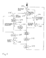
- the step S12 may be started directly after step S11, however, as shown in Fig. 5 , the control device may wait for a suitable moment to activate the internal cleaning in place, for example it may be checked whether enough clean water is in buffer tank 16 to meet the demands of cleaned water during the chemical cleaning process.
- Step S10 If in Step S10 it is detected that no internal cleaning in place flag for a chemical cleaning has been set, step S14 will follow and it is checked whether an absolute transmembran pressure value TMP has increased with more than a predefined limit ZZ since the last internal cleaning in place. If yes, step S12 will follow as explained before. If not, step S15 will follow in which it is checked when the last internal cleaning in place took place. If the last internal cleaning in place is more than a predetermined time period ago, e. g. a predefined number of days BB ago then step S12 will follow and a chemical cleaning is activated. If there are less than BB days since the last chemical cleaning the routine will start with step S10 again.
- a predetermined time period ago e. g. a predefined number of days BB ago
- step S16 will follow, where it is checked whether a minimum feed pump flow of the feed pump 6 has been reached. If the minimum feed pump flow has been reached step S17 will follow and the system will be stopped. In this case an external cleaning in place process CIP has to be carried out as checked in step S18. After carrying out a cleaning in place process all counters will be reset in step S13 and the control routine will start again with step S10.
- step S16 it is detected that the minimum feed pump flow has not been reached in following step S19 the feed pump flow will be reduced by a predetermined amount. This means that a too fast clogging of the filter 2 is prevented by reducing the flow of water to be cleaned through filter 2. By this, the production of the system can be maintained and an additional down-time for cleaning can be avoided.
- step S19 in step S20 it is checked whether the flow has been reduced before or whether a minimum flow is reached.
- This control device may be designed so that it is possible to reduce the feed pump flow only once before carrying out a cleaning in place process CIP. However, alternatively it may be possible that the control device may reduce the feed pump flow in several steps. Then a reduction can be carried out in these several steps until the minimum flow is reached.
- step S12 will follow and the chemical cleaning is activated in step S12, if necessary after waiting for an opportunity for activation.
- a warning will be sent in step S21 before the activation of the internal cleaning n place in step S12. This warning may be sent to a service informing the service in advance that a cleaning in place CIP will become necessary in near future.
Priority Applications (5)
| Application Number | Priority Date | Filing Date | Title |
|---|---|---|---|
| EP12197645.0A EP2745916B1 (fr) | 2012-12-18 | 2012-12-18 | Procédé de nettoyage d'un filtre de fluide liquide |
| IN3301DEN2015 IN2015DN03301A (fr) | 2012-12-18 | 2013-11-29 | |
| SG11201503267RA SG11201503267RA (en) | 2012-12-18 | 2013-11-29 | Method of cleaning a liquid fluid filter |
| CN201380066550.7A CN104884151B (zh) | 2012-12-18 | 2013-11-29 | 清洗液流过滤器的方法 |
| PCT/EP2013/075062 WO2014095302A1 (fr) | 2012-12-18 | 2013-11-29 | Procédé de nettoyage d'un filtre à fluide liquide |
Applications Claiming Priority (1)
| Application Number | Priority Date | Filing Date | Title |
|---|---|---|---|
| EP12197645.0A EP2745916B1 (fr) | 2012-12-18 | 2012-12-18 | Procédé de nettoyage d'un filtre de fluide liquide |
Publications (2)
| Publication Number | Publication Date |
|---|---|
| EP2745916A1 true EP2745916A1 (fr) | 2014-06-25 |
| EP2745916B1 EP2745916B1 (fr) | 2018-01-24 |
Family
ID=47458679
Family Applications (1)
| Application Number | Title | Priority Date | Filing Date |
|---|---|---|---|
| EP12197645.0A Active EP2745916B1 (fr) | 2012-12-18 | 2012-12-18 | Procédé de nettoyage d'un filtre de fluide liquide |
Country Status (5)
| Country | Link |
|---|---|
| EP (1) | EP2745916B1 (fr) |
| CN (1) | CN104884151B (fr) |
| IN (1) | IN2015DN03301A (fr) |
| SG (1) | SG11201503267RA (fr) |
| WO (1) | WO2014095302A1 (fr) |
Cited By (3)
| Publication number | Priority date | Publication date | Assignee | Title |
|---|---|---|---|---|
| WO2017013027A1 (fr) * | 2015-07-18 | 2017-01-26 | Vetco Gray Scandinavia As | Procédés et systèmes de commande d'injection d'eau de mer |
| US20210291118A1 (en) * | 2020-03-18 | 2021-09-23 | Grundfos Holding A/S | Cleaning-in-place method and filter device |
| WO2023202976A1 (fr) * | 2022-04-20 | 2023-10-26 | Grundfos Holding A/S | Procédé de nettoyage en place adaptatif pour un système de filtration à membrane |
Families Citing this family (5)
| Publication number | Priority date | Publication date | Assignee | Title |
|---|---|---|---|---|
| CN108627438B (zh) * | 2017-03-23 | 2020-11-17 | 天华化工机械及自动化研究设计院有限公司 | 旋转压力过滤机试验装置、测试方法及过滤机设计方法 |
| JP6501421B2 (ja) * | 2017-07-07 | 2019-04-17 | 旭化成メディカル株式会社 | 体腔液処理装置 |
| CN109966925B (zh) * | 2019-03-02 | 2023-11-24 | 汤宇 | 一种闪爆法反冲清膜工艺及其装置 |
| DE102020122029A1 (de) | 2020-08-24 | 2022-02-24 | Krones Aktiengesellschaft | Verfahren zur Regelung einer Filtrationseinheit |
| CN114198833B (zh) * | 2021-11-17 | 2023-08-15 | 青岛海尔空调电子有限公司 | 用于控制加湿器的方法、装置、加湿器和存储介质 |
Citations (4)
| Publication number | Priority date | Publication date | Assignee | Title |
|---|---|---|---|---|
| US4921610A (en) * | 1986-09-04 | 1990-05-01 | Memtec Limited | Cleaning of hollow fibre filters |
| US5647988A (en) * | 1994-05-30 | 1997-07-15 | Kubota Corporation | Method of back-washing submerged-type ceramic membrane separation apparatus |
| US20110042312A1 (en) * | 2005-07-12 | 2011-02-24 | Boris Fernandes Ginzburg | Process control for an immersed membrane system |
| US20110067737A1 (en) * | 2008-05-30 | 2011-03-24 | Beijing Ecojoy Water Technology Co., Ltd. | Method and apparatus for cleaning a film seperating device |
Family Cites Families (3)
| Publication number | Priority date | Publication date | Assignee | Title |
|---|---|---|---|---|
| CN101530747A (zh) * | 2009-03-06 | 2009-09-16 | 东莞市红树林环保科技有限公司 | 一种膜组件组合式脉冲反冲洗工艺 |
| CN101524625A (zh) * | 2009-03-31 | 2009-09-09 | 大连理工大学 | 一种多孔分离膜的清洗方法 |
| CN102485328A (zh) * | 2010-12-02 | 2012-06-06 | 东丽纤维研究所(中国)有限公司 | 一种浸没式膜过滤系统的清洗方法 |
-
2012
- 2012-12-18 EP EP12197645.0A patent/EP2745916B1/fr active Active
-
2013
- 2013-11-29 SG SG11201503267RA patent/SG11201503267RA/en unknown
- 2013-11-29 CN CN201380066550.7A patent/CN104884151B/zh active Active
- 2013-11-29 IN IN3301DEN2015 patent/IN2015DN03301A/en unknown
- 2013-11-29 WO PCT/EP2013/075062 patent/WO2014095302A1/fr active Application Filing
Patent Citations (4)
| Publication number | Priority date | Publication date | Assignee | Title |
|---|---|---|---|---|
| US4921610A (en) * | 1986-09-04 | 1990-05-01 | Memtec Limited | Cleaning of hollow fibre filters |
| US5647988A (en) * | 1994-05-30 | 1997-07-15 | Kubota Corporation | Method of back-washing submerged-type ceramic membrane separation apparatus |
| US20110042312A1 (en) * | 2005-07-12 | 2011-02-24 | Boris Fernandes Ginzburg | Process control for an immersed membrane system |
| US20110067737A1 (en) * | 2008-05-30 | 2011-03-24 | Beijing Ecojoy Water Technology Co., Ltd. | Method and apparatus for cleaning a film seperating device |
Cited By (5)
| Publication number | Priority date | Publication date | Assignee | Title |
|---|---|---|---|---|
| WO2017013027A1 (fr) * | 2015-07-18 | 2017-01-26 | Vetco Gray Scandinavia As | Procédés et systèmes de commande d'injection d'eau de mer |
| GB2556527A (en) * | 2015-07-18 | 2018-05-30 | Vetco Gray Scandinavia As | Seawater injection control methods and systems |
| GB2556527B (en) * | 2015-07-18 | 2020-05-27 | Vetco Gray Scandinavia As | Seawater injection control methods and systems |
| US20210291118A1 (en) * | 2020-03-18 | 2021-09-23 | Grundfos Holding A/S | Cleaning-in-place method and filter device |
| WO2023202976A1 (fr) * | 2022-04-20 | 2023-10-26 | Grundfos Holding A/S | Procédé de nettoyage en place adaptatif pour un système de filtration à membrane |
Also Published As
| Publication number | Publication date |
|---|---|
| SG11201503267RA (en) | 2015-05-28 |
| WO2014095302A1 (fr) | 2014-06-26 |
| CN104884151A (zh) | 2015-09-02 |
| CN104884151B (zh) | 2018-04-03 |
| EP2745916B1 (fr) | 2018-01-24 |
| IN2015DN03301A (fr) | 2015-10-09 |
Similar Documents
| Publication | Publication Date | Title |
|---|---|---|
| EP2745916B1 (fr) | Procédé de nettoyage d'un filtre de fluide liquide | |
| US6001254A (en) | Method of operating and monitoring a group of filter membrane modules, and a group of modules implementing the method | |
| US20220145596A1 (en) | Residential grey water recycling system | |
| CN112299510B (zh) | 净水机、净水系统及其控制方法 | |
| CA2676534A1 (fr) | Sequence d'evacuation-lavage et systeme pour module de filtre | |
| JP2015042385A (ja) | 淡水化システム | |
| EP2718237A1 (fr) | Système de commande pour des installations de traitement des eaux usées par des bioréacteurs à membranes | |
| JP3924919B2 (ja) | 水ろ過処理装置 | |
| CN112142214A (zh) | 净水器及其控制方法和装置 | |
| JP3473309B2 (ja) | 膜分離装置の運転制御装置 | |
| JP5588099B2 (ja) | 膜ろ過処理法及び膜ろ過処理装置 | |
| EP2745917B1 (fr) | Ensemble filtre de fluide liquide | |
| JP2011078889A (ja) | 濾過部材洗浄システム | |
| JP2012176343A (ja) | 膜濾過装置 | |
| JPH11169851A (ja) | 水ろ過処理装置およびその運転方法 | |
| CN213802961U (zh) | 净水机及其净水系统 | |
| JP7083271B2 (ja) | 可搬型浄水処理装置 | |
| CN214360551U (zh) | 净水器 | |
| KR101481075B1 (ko) | 침지식 연속유동 막여과장치 및 그의 역세척방법 | |
| JP6664673B1 (ja) | 濾過システム | |
| JP3601015B2 (ja) | 膜を用いた濾過方法 | |
| CN210683297U (zh) | 一种净水控制装置及净水设备 | |
| WO2015146626A1 (fr) | Dispositif de prétraitement pour mesure en ligne dans un système d'eau, dispositif de mesure en ligne le comprenant, et procédé de traitement pour mesure en ligne | |
| CN212369691U (zh) | 改进的直滤系统 | |
| JP7222055B1 (ja) | 膜濾過機及び膜濾過機の洗浄方法 |
Legal Events
| Date | Code | Title | Description |
|---|---|---|---|
| PUAI | Public reference made under article 153(3) epc to a published international application that has entered the european phase |
Free format text: ORIGINAL CODE: 0009012 |
|
| 17P | Request for examination filed |
Effective date: 20121218 |
|
| AK | Designated contracting states |
Kind code of ref document: A1 Designated state(s): AL AT BE BG CH CY CZ DE DK EE ES FI FR GB GR HR HU IE IS IT LI LT LU LV MC MK MT NL NO PL PT RO RS SE SI SK SM TR |
|
| AX | Request for extension of the european patent |
Extension state: BA ME |
|
| R17P | Request for examination filed (corrected) |
Effective date: 20141217 |
|
| RBV | Designated contracting states (corrected) |
Designated state(s): AL AT BE BG CH CY CZ DE DK EE ES FI FR GB GR HR HU IE IS IT LI LT LU LV MC MK MT NL NO PL PT RO RS SE SI SK SM TR |
|
| STAA | Information on the status of an ep patent application or granted ep patent |
Free format text: STATUS: EXAMINATION IS IN PROGRESS |
|
| 17Q | First examination report despatched |
Effective date: 20161122 |
|
| GRAP | Despatch of communication of intention to grant a patent |
Free format text: ORIGINAL CODE: EPIDOSNIGR1 |
|
| STAA | Information on the status of an ep patent application or granted ep patent |
Free format text: STATUS: GRANT OF PATENT IS INTENDED |
|
| INTG | Intention to grant announced |
Effective date: 20170623 |
|
| GRAJ | Information related to disapproval of communication of intention to grant by the applicant or resumption of examination proceedings by the epo deleted |
Free format text: ORIGINAL CODE: EPIDOSDIGR1 |
|
| STAA | Information on the status of an ep patent application or granted ep patent |
Free format text: STATUS: EXAMINATION IS IN PROGRESS |
|
| GRAS | Grant fee paid |
Free format text: ORIGINAL CODE: EPIDOSNIGR3 |
|
| STAA | Information on the status of an ep patent application or granted ep patent |
Free format text: STATUS: GRANT OF PATENT IS INTENDED |
|
| GRAP | Despatch of communication of intention to grant a patent |
Free format text: ORIGINAL CODE: EPIDOSNIGR1 |
|
| INTC | Intention to grant announced (deleted) | ||
| GRAA | (expected) grant |
Free format text: ORIGINAL CODE: 0009210 |
|
| STAA | Information on the status of an ep patent application or granted ep patent |
Free format text: STATUS: THE PATENT HAS BEEN GRANTED |
|
| INTG | Intention to grant announced |
Effective date: 20171208 |
|
| AK | Designated contracting states |
Kind code of ref document: B1 Designated state(s): AL AT BE BG CH CY CZ DE DK EE ES FI FR GB GR HR HU IE IS IT LI LT LU LV MC MK MT NL NO PL PT RO RS SE SI SK SM TR |
|
| REG | Reference to a national code |
Ref country code: GB Ref legal event code: FG4D |
|
| REG | Reference to a national code |
Ref country code: CH Ref legal event code: EP |
|
| REG | Reference to a national code |
Ref country code: AT Ref legal event code: REF Ref document number: 965472 Country of ref document: AT Kind code of ref document: T Effective date: 20180215 |
|
| REG | Reference to a national code |
Ref country code: IE Ref legal event code: FG4D |
|
| REG | Reference to a national code |
Ref country code: DE Ref legal event code: R096 Ref document number: 602012042287 Country of ref document: DE |
|
| REG | Reference to a national code |
Ref country code: NL Ref legal event code: FP |
|
| REG | Reference to a national code |
Ref country code: LT Ref legal event code: MG4D |
|
| REG | Reference to a national code |
Ref country code: AT Ref legal event code: MK05 Ref document number: 965472 Country of ref document: AT Kind code of ref document: T Effective date: 20180124 |
|
| PG25 | Lapsed in a contracting state [announced via postgrant information from national office to epo] |
Ref country code: HR Free format text: LAPSE BECAUSE OF FAILURE TO SUBMIT A TRANSLATION OF THE DESCRIPTION OR TO PAY THE FEE WITHIN THE PRESCRIBED TIME-LIMIT Effective date: 20180124 Ref country code: LT Free format text: LAPSE BECAUSE OF FAILURE TO SUBMIT A TRANSLATION OF THE DESCRIPTION OR TO PAY THE FEE WITHIN THE PRESCRIBED TIME-LIMIT Effective date: 20180124 Ref country code: CY Free format text: LAPSE BECAUSE OF FAILURE TO SUBMIT A TRANSLATION OF THE DESCRIPTION OR TO PAY THE FEE WITHIN THE PRESCRIBED TIME-LIMIT Effective date: 20180124 Ref country code: FI Free format text: LAPSE BECAUSE OF FAILURE TO SUBMIT A TRANSLATION OF THE DESCRIPTION OR TO PAY THE FEE WITHIN THE PRESCRIBED TIME-LIMIT Effective date: 20180124 Ref country code: NO Free format text: LAPSE BECAUSE OF FAILURE TO SUBMIT A TRANSLATION OF THE DESCRIPTION OR TO PAY THE FEE WITHIN THE PRESCRIBED TIME-LIMIT Effective date: 20180424 Ref country code: ES Free format text: LAPSE BECAUSE OF FAILURE TO SUBMIT A TRANSLATION OF THE DESCRIPTION OR TO PAY THE FEE WITHIN THE PRESCRIBED TIME-LIMIT Effective date: 20180124 |
|
| PG25 | Lapsed in a contracting state [announced via postgrant information from national office to epo] |
Ref country code: AT Free format text: LAPSE BECAUSE OF FAILURE TO SUBMIT A TRANSLATION OF THE DESCRIPTION OR TO PAY THE FEE WITHIN THE PRESCRIBED TIME-LIMIT Effective date: 20180124 Ref country code: PL Free format text: LAPSE BECAUSE OF FAILURE TO SUBMIT A TRANSLATION OF THE DESCRIPTION OR TO PAY THE FEE WITHIN THE PRESCRIBED TIME-LIMIT Effective date: 20180124 Ref country code: RS Free format text: LAPSE BECAUSE OF FAILURE TO SUBMIT A TRANSLATION OF THE DESCRIPTION OR TO PAY THE FEE WITHIN THE PRESCRIBED TIME-LIMIT Effective date: 20180124 Ref country code: GR Free format text: LAPSE BECAUSE OF FAILURE TO SUBMIT A TRANSLATION OF THE DESCRIPTION OR TO PAY THE FEE WITHIN THE PRESCRIBED TIME-LIMIT Effective date: 20180425 Ref country code: LV Free format text: LAPSE BECAUSE OF FAILURE TO SUBMIT A TRANSLATION OF THE DESCRIPTION OR TO PAY THE FEE WITHIN THE PRESCRIBED TIME-LIMIT Effective date: 20180124 Ref country code: SE Free format text: LAPSE BECAUSE OF FAILURE TO SUBMIT A TRANSLATION OF THE DESCRIPTION OR TO PAY THE FEE WITHIN THE PRESCRIBED TIME-LIMIT Effective date: 20180124 Ref country code: IS Free format text: LAPSE BECAUSE OF FAILURE TO SUBMIT A TRANSLATION OF THE DESCRIPTION OR TO PAY THE FEE WITHIN THE PRESCRIBED TIME-LIMIT Effective date: 20180524 Ref country code: BG Free format text: LAPSE BECAUSE OF FAILURE TO SUBMIT A TRANSLATION OF THE DESCRIPTION OR TO PAY THE FEE WITHIN THE PRESCRIBED TIME-LIMIT Effective date: 20180424 |
|
| REG | Reference to a national code |
Ref country code: DE Ref legal event code: R097 Ref document number: 602012042287 Country of ref document: DE |
|
| PG25 | Lapsed in a contracting state [announced via postgrant information from national office to epo] |
Ref country code: AL Free format text: LAPSE BECAUSE OF FAILURE TO SUBMIT A TRANSLATION OF THE DESCRIPTION OR TO PAY THE FEE WITHIN THE PRESCRIBED TIME-LIMIT Effective date: 20180124 Ref country code: EE Free format text: LAPSE BECAUSE OF FAILURE TO SUBMIT A TRANSLATION OF THE DESCRIPTION OR TO PAY THE FEE WITHIN THE PRESCRIBED TIME-LIMIT Effective date: 20180124 Ref country code: RO Free format text: LAPSE BECAUSE OF FAILURE TO SUBMIT A TRANSLATION OF THE DESCRIPTION OR TO PAY THE FEE WITHIN THE PRESCRIBED TIME-LIMIT Effective date: 20180124 |
|
| PG25 | Lapsed in a contracting state [announced via postgrant information from national office to epo] |
Ref country code: SK Free format text: LAPSE BECAUSE OF FAILURE TO SUBMIT A TRANSLATION OF THE DESCRIPTION OR TO PAY THE FEE WITHIN THE PRESCRIBED TIME-LIMIT Effective date: 20180124 Ref country code: CZ Free format text: LAPSE BECAUSE OF FAILURE TO SUBMIT A TRANSLATION OF THE DESCRIPTION OR TO PAY THE FEE WITHIN THE PRESCRIBED TIME-LIMIT Effective date: 20180124 Ref country code: DK Free format text: LAPSE BECAUSE OF FAILURE TO SUBMIT A TRANSLATION OF THE DESCRIPTION OR TO PAY THE FEE WITHIN THE PRESCRIBED TIME-LIMIT Effective date: 20180124 Ref country code: SM Free format text: LAPSE BECAUSE OF FAILURE TO SUBMIT A TRANSLATION OF THE DESCRIPTION OR TO PAY THE FEE WITHIN THE PRESCRIBED TIME-LIMIT Effective date: 20180124 |
|
| PLBE | No opposition filed within time limit |
Free format text: ORIGINAL CODE: 0009261 |
|
| STAA | Information on the status of an ep patent application or granted ep patent |
Free format text: STATUS: NO OPPOSITION FILED WITHIN TIME LIMIT |
|
| 26N | No opposition filed |
Effective date: 20181025 |
|
| PG25 | Lapsed in a contracting state [announced via postgrant information from national office to epo] |
Ref country code: SI Free format text: LAPSE BECAUSE OF FAILURE TO SUBMIT A TRANSLATION OF THE DESCRIPTION OR TO PAY THE FEE WITHIN THE PRESCRIBED TIME-LIMIT Effective date: 20180124 |
|
| REG | Reference to a national code |
Ref country code: CH Ref legal event code: PL |
|
| PG25 | Lapsed in a contracting state [announced via postgrant information from national office to epo] |
Ref country code: MC Free format text: LAPSE BECAUSE OF FAILURE TO SUBMIT A TRANSLATION OF THE DESCRIPTION OR TO PAY THE FEE WITHIN THE PRESCRIBED TIME-LIMIT Effective date: 20180124 Ref country code: LU Free format text: LAPSE BECAUSE OF NON-PAYMENT OF DUE FEES Effective date: 20181218 |
|
| REG | Reference to a national code |
Ref country code: IE Ref legal event code: MM4A |
|
| REG | Reference to a national code |
Ref country code: BE Ref legal event code: MM Effective date: 20181231 |
|
| PG25 | Lapsed in a contracting state [announced via postgrant information from national office to epo] |
Ref country code: IE Free format text: LAPSE BECAUSE OF NON-PAYMENT OF DUE FEES Effective date: 20181218 |
|
| PG25 | Lapsed in a contracting state [announced via postgrant information from national office to epo] |
Ref country code: BE Free format text: LAPSE BECAUSE OF NON-PAYMENT OF DUE FEES Effective date: 20181231 |
|
| PG25 | Lapsed in a contracting state [announced via postgrant information from national office to epo] |
Ref country code: CH Free format text: LAPSE BECAUSE OF NON-PAYMENT OF DUE FEES Effective date: 20181231 Ref country code: LI Free format text: LAPSE BECAUSE OF NON-PAYMENT OF DUE FEES Effective date: 20181231 |
|
| PG25 | Lapsed in a contracting state [announced via postgrant information from national office to epo] |
Ref country code: MT Free format text: LAPSE BECAUSE OF NON-PAYMENT OF DUE FEES Effective date: 20181218 |
|
| PG25 | Lapsed in a contracting state [announced via postgrant information from national office to epo] |
Ref country code: TR Free format text: LAPSE BECAUSE OF FAILURE TO SUBMIT A TRANSLATION OF THE DESCRIPTION OR TO PAY THE FEE WITHIN THE PRESCRIBED TIME-LIMIT Effective date: 20180124 |
|
| PG25 | Lapsed in a contracting state [announced via postgrant information from national office to epo] |
Ref country code: PT Free format text: LAPSE BECAUSE OF FAILURE TO SUBMIT A TRANSLATION OF THE DESCRIPTION OR TO PAY THE FEE WITHIN THE PRESCRIBED TIME-LIMIT Effective date: 20180124 |
|
| PG25 | Lapsed in a contracting state [announced via postgrant information from national office to epo] |
Ref country code: HU Free format text: LAPSE BECAUSE OF FAILURE TO SUBMIT A TRANSLATION OF THE DESCRIPTION OR TO PAY THE FEE WITHIN THE PRESCRIBED TIME-LIMIT; INVALID AB INITIO Effective date: 20121218 Ref country code: MK Free format text: LAPSE BECAUSE OF NON-PAYMENT OF DUE FEES Effective date: 20180124 |
|
| REG | Reference to a national code |
Ref country code: DE Ref legal event code: R082 Ref document number: 602012042287 Country of ref document: DE |
|
| PGFP | Annual fee paid to national office [announced via postgrant information from national office to epo] |
Ref country code: GB Payment date: 20231220 Year of fee payment: 12 |
|
| PGFP | Annual fee paid to national office [announced via postgrant information from national office to epo] |
Ref country code: NL Payment date: 20231220 Year of fee payment: 12 Ref country code: IT Payment date: 20231228 Year of fee payment: 12 Ref country code: FR Payment date: 20231221 Year of fee payment: 12 Ref country code: DE Payment date: 20231214 Year of fee payment: 12 |