EP2745672B1 - Machine agricole de récolte comportant un dispositif de guidage perfectionné des végétaux - Google Patents
Machine agricole de récolte comportant un dispositif de guidage perfectionné des végétaux Download PDFInfo
- Publication number
- EP2745672B1 EP2745672B1 EP13306686.0A EP13306686A EP2745672B1 EP 2745672 B1 EP2745672 B1 EP 2745672B1 EP 13306686 A EP13306686 A EP 13306686A EP 2745672 B1 EP2745672 B1 EP 2745672B1
- Authority
- EP
- European Patent Office
- Prior art keywords
- machine according
- agricultural machine
- guiding
- guiding device
- pick
- Prior art date
- Legal status (The legal status is an assumption and is not a legal conclusion. Google has not performed a legal analysis and makes no representation as to the accuracy of the status listed.)
- Active
Links
Images


Classifications
-
- A—HUMAN NECESSITIES
- A01—AGRICULTURE; FORESTRY; ANIMAL HUSBANDRY; HUNTING; TRAPPING; FISHING
- A01D—HARVESTING; MOWING
- A01D89/00—Pick-ups for loaders, chaff-cutters, balers, field-threshers, or the like, i.e. attachments for picking-up hay or the like field crops
- A01D89/006—Accessories
- A01D89/008—Devices cooperating with the pick-up
Definitions
- the present invention relates to an agricultural machine for harvesting fodder having a frame to which is connected a structure located, at least partially, above at least one soil collecting device, which device having teeth with tooth tips describing a curved envelope when the teeth are animated, the machine also comprising at least one collected plant treatment device located near the collection device, and a plant guide device located at least partially above and at a reduced distance from the collecting device, the guiding device being movable relative to the pickup device around an instantaneous center of main rotation, by means of a displacement device comprising a first connecting means and a second connecting means from the guiding device to the structure, the first connecting means allowing the device e guide pivoting about a first instantaneous center of rotation, the second connecting means allowing the guide device to pivot about a second instantaneous center of rotation, the displacement device can be placed in at least a first position and a second position, the guiding device comprising a front portion having a lower end end, a rear portion delimited by a rear end, and an intermediate portion connecting
- the pickup device comprises a rotor with teeth of the "pick-up" type.
- the rotor is partially surrounded by a guide surface formed for example by a set of curved blades between which rotate the teeth carried by the rotor, and with respect to which curved blades the tips of teeth emerge.
- the teeth pick up the plants at ground level, raise them and project them backwards along the guide surface.
- the lower end of the guide device is raised strongly above the ground to allow passage of a swath of high volume to the pickup device.
- the intermediate portion of the guide device extends substantially horizontally above the pickup device and substantially at the same height as the lower end end, from which the intermediate portion is far away from the teeth tips of the pickup device.
- the intermediate portion of the guide device can not properly maintain the plants in contact with the teeth which are in front and on the top of the pickup device.
- the plants are driven irregularly to the downstream processing device.
- a harmful accumulation of plants can occur between the collection device and the treatment device, or within the latter.
- the known machine also has a second position provided in particular for the collection of windrows light or small volume. In this position, the lower end of the guide device is closer to the ground than in the first position.
- the present invention aims to provide an agricultural machine for forage harvesting that does not have the aforementioned drawbacks.
- a large volume of plants, heavy, with long strands or in the form of windrow can pass under the lower end of the guide device, downstream of which these plants are well taken up by the teeth of the pickup device.
- the machine according to the invention also allows plants with short or light strands, spread out on the ground on a low height, to be fully collected by avoiding that part of them is found projected forward. These plants collected are then quickly moved to the treatment device and directed and / or distributed thereon optimally.
- first connecting means and the second connecting means are geometrically and / or elastically configured so that in the first position, the lower end end is strongly raised at the first position. above the ground and that the intermediate portion is closer to the tines of the pickup device, and that in the second position, the lower end end is closely close to the ground and the intermediate portion and the rear portion are away from the tips teeth of the pickup device.
- the tips of teeth cooperate with almost all the plants that pass between the pickup device and the intermediate portion of the guide device.
- the risk of plants standing between the plant and the tips of the teeth is greatly reduced.
- the collected plants feed the treatment device with regularity.
- the rear end of the guiding device is also brought closer to the tips of the teeth of the pickup device, the teeth of which penetrate the flow of plants and carry it over the entire extent of the guiding device. located above the pickup device.
- the distance of the intermediate portion and the rear portion relative to the collection device increases the section of passage of plants downstream of the lower end of the guide device.
- light or short-stranded plants are accelerated and have, at their output from the pickup device, a high speed to be projected at the optimal location on the treatment device or to be distributed over the entire surface thereof .
- This prevents such plants arrive only at the input of the treatment device, or even accumulate between the latter and the collection device.
- the invention allows the latter to have a regular appearance.
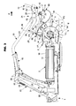
- the agricultural machine comprises a frame (1) connectable to a tractor, not shown, for moving in a direction of advance (A).
- A a direction of advance
- this frame (1) carries a plant collecting device (2) on the ground and a treatment device (3) placed downstream.
- the pick-up device (2) has a curved guide surface (4) which surrounds a rotor (5) which is rotated about an axis of rotation (6) in the anticlockwise direction (7), seen from the right of the pick-up device (2).
- the latter also has teeth (8) which pick up the plants at ground level, raise them and project them backwards.
- the teeth (8) have tooth tips (9) which describe a curved envelope (10) when the teeth (8) are animated.
- the teeth (8) emerge at least partially from the guide surface (4).
- the guide surface (4) has an upper end (11) and a lower end (12) located substantially vertically above the axis of rotation (6) of the rotor (5).
- the pickup device (2) is pick-up type, whose teeth (8) are carried by the rotor (5) and emerge from the guide surface (4) formed by a plurality of blades curved around the rotor (5) and placed next to each other along the axis of rotation (6). The teeth (8) move between these blades.
- the guide surface (4) is fixed.
- the teeth (8) are controlled so that the curved envelope (10) described by the displacement of the tooth tips (9) is not cylindrical. Indeed, as is apparent for example from the figure 2 , the teeth (8) retract inside the guide surface (4) after having crossed the upper end (11). In this way, the teeth (8) gradually release the plants that approach the treatment device (3).
- Such displacement of the teeth (8) is obtained by means of, for example, a fixed cam path inside which rollers carried by cams connected to the teeth (8) move.
- teeth (8) not controlled are also possible.
- the curved envelope (10) described by the tooth tips (9) is a cylinder centered on the axis of rotation (6) of the rotor (5).
- the latter can thus comprise a flexible band wound around a first rotor placed at the front of the pickup device (2) and around a second rotor placed further back.
- This second rotor can in particular be placed, at work, at a higher distance from the ground than the first rotor, so that the pickup device (2) moves the plants backward and upward towards the device treatment (3).
- Such a band has teeth, forks or hooks that can be attached or hinged to the band.
- the guide surface (4) is constituted by the surface of the web in contact with the plants.
- the guide surface (4) is in this case animated.
- the axis of rotation (6) of the rotor (5) is that of the first rotor.
- the upper end (11) and the lower end (12) of the guide surface (4) are located substantially vertically above the axis of rotation (6) of the first rotor, at the level of the upper part respectively the lower part of the first rotor.
- the pickup device (2) is driven by means of any suitable device. It can be a motor (13) hydraulic or electric, which motor (13) can be housed inside the rotor or project laterally thereof.
- the pickup device (2) can also be driven by means of a chain or a belt, or a cascade of gables. A combination of such means is also possible.
- the treatment device (3) collected plants is located at the rear and near the collection device (2) so that it receives the plants projected back by it.
- this processing device (3) comprises a belt conveyor (14).
- This band (14) is driven during work so that it moves said plants transversely to the pickup device (2).
- the plants are then re-deposited on the ground in the form of a swath for later recovery.
- a deflector (15) which comprises a substantially vertical portion to limit the rearward projection of the plants.
- the deflector (15) may also comprise another substantially horizontal portion to limit plant projections upwards. In the exemplary embodiments of the figures, this other portion is placed in the continuity of the substantially vertical portion, above the belt conveyor (14).
- the processing device (3) can also be a roller conveyor, the latter being for example mounted on axes of rotation oriented, at work, substantially in the direction of advance (A). Such rollers are preferably placed next to each other and at a short distance from each other, and can be driven such that the plants are moved transversely to the pickup device (2).
- the drive of the treatment device (3) for example the belt conveyor (14) or said rollers, is carried out by means of any suitable organ. It can be a hydraulic or electric motor. An animation by means of a chain or a belt, or a cascade of gables, is also possible. A combination of such means is of course possible. These means can be operated in one operating direction or in the other. Especially in the case of a conveyor belt (14) or rollers, the plants can in this way be transferred to the left side or the right side of the machine, for example to form a swath on one side or the other. 'other.
- the treatment device (3) comprises an upper envelope (16).
- this envelope (16) is constituted by the upper surface of the strip (14) which receives the plants moved by the pickup device (2).
- this upper surface extends, at work, to substantially parallel to the ground.
- the conveyor belt (14) has strips attached to the strip (14). These bars are oriented substantially perpendicular to the direction of movement of the strip (14). These bars emerge from the upper surface of the strip (14).
- the upper casing (16) is a substantially planar dummy surface that rests on the top of the rollers.
- the machine may have a plurality of pickup devices (2) and processing devices (3) placed side by side to increase its working width.
- a guide device (17) for the plants is located at least partially above and at a reduced distance from the pickup device (2).
- the guiding device (17) comprises flexible rods (18) which are substantially parallel to each other and which extend from the front of the pick-up device (2) towards the rear.
- These rods (18) additionally hold the plants in engagement with the teeth (8), at least over part of the height of the teeth (8).
- the rods (18) of the guiding device (17) are fixed on a bar (19). They each comprise a spring portion (20) formed for example by a coil-shaped winding of the wire which comprises the rod (18).
- each spring portion (20) is threaded onto the bar (19) and held by a bolt.
- the bar (19) is connected to two bars (21) which extend rearwardly from the bar (19).
- Each bar (21) is located under a structure (22) carrying the guide device (17).
- This structure (22) is connected to the frame (1) which carries it, and it is located at least partially above the pickup device (2).
- This structure (22) comprises arms (23) which carry the guiding device (17) and extend rearwardly over the treatment device (3).
- Each bar (21) of the guiding device (17) is movably carried by the arm (23) corresponding by means of a displacement device (24) having two connecting means (25 and 26).
- the guide device (17) is thus movable relative to the pickup device (2) by means of the displacement device (24) carried by the arm (23), around an instantaneous center of principal rotation (27).
- the instantaneous center of rotation main (27) moves according to a particular law dictated by the arrangement of the displacement device (24), which arrangement is the subject of a detailed description in the following text.
- the arms (23) are connected near their rear ends to supports (28) connected to the frame (1). These arms (23) are thus remote from the pickup device (2) and the treatment device (3) so as not to hinder the movements of the plants.
- the arms (23) are hinged relative to the frame (1) by means of axes (29) substantially horizontal. These axes (29) are carried by the supports (28). In a working configuration illustrated in particular in the figure 1 these axes (29) are positioned above the rear part of the treatment device (3).
- the arms (23) can pivot upwardly at an angle about these axes (29).
- each of these stops (30) is constituted by a rod (31) whose one end is hinged to the frame (1) and the other end is engaged in a sleeve (32) which is articulated on the end of one of the arms (23).
- the end engaged in the sheath (32) is provided with a shoulder located between two stops placed at both ends of said sheath (32). Said stops limit the possible movement of the sleeve (32) relative to the shoulder of the rod (31) and therefore the pivot angle of the arms (23) about the hinge pins (29).
- a compression spring (33) Between the rod (31) and the sleeve (32) of each stop (30) is disposed a compression spring (33).
- the supports (28) of the arms (23) are connected to the frame (1) by means of substantially horizontal hinge pins (34) located at the rear of the treatment device (3) and around which they can be moved. These supports (28) thus form with the stops (30), the ends of the arms (23) and parts of the frame (1) deformable parallelograms. These parallelograms make it possible to move and maintain the arms (23) and the guiding device (17) in the working configuration and in a transport configuration, in particular.
- the machine may comprise, between the frame (1) and the supports (28), cylinders, for example hydraulic, not shown, for moving these supports (28) around the axes (34). These cylinders can be controlled from the tractor so that they make said movements.
- This arrangement thus makes it possible to transpose the machine into the road transport configuration in which its dimensions are reduced.
- this configuration by pivoting the supports (28) about the axes (34) in a clockwise direction, seen from the right, the arms (23) are brought into a position very close to the treatment device (3).
- guide (17) is then substantially in the extension of the pickup device (2) and these three devices (2, 3 and 17) are additionally brought closer to the vertical by pivoting about a substantially horizontal axis (35) of the built (1).
- This displacement to the vertical is performed by means of a jack, for example hydraulic, placed under the treatment device (3) and resting on the frame (1).
- these devices (2, 3 and 17) can then be folded together backwards or forwards with part of the frame (1), around a substantially vertical axis, to be oriented in the direction of advancement (A).
- the displacement device (24) comprises a first connecting means (25) and a second connecting means (26) of the guiding device (17) to the structure (22).
- the first connecting means (25) comprises a first connecting rod (36) connected to the structure (22) by a first articulation (37) and to the guiding device (17) by a second articulation (38).
- the first connecting means (25) allows the guiding device (17) to pivot about a first instantaneous center of rotation (39). This is real because constituted, in this example, by a center of the first articulation (37).
- the second connecting means (26) comprises a second connecting rod (40) connected to the structure (22) by a third articulation (41) and to the guiding device (17) by a fourth articulation (42).
- the second connecting means (26) allows the guiding device (17) to pivot about a second instantaneous center of rotation (43).
- the latter also real, is constituted in this example by a center of the third articulation (41).
- These various joints (37, 38, 41 and 42) are for example constituted by axes extending, at work, substantially perpendicular to the direction of advance (A) of the machine.
- the first connecting means (25) comprises a first guide path (44) connected to the structure (22). Within this first path (44), a first axis (45) connected to the guide device (17) can move around the first instantaneous center of rotation (39).
- the arm (23) carries a side plate in which is formed a light forming said first guide path (44). Inside this light is inserted the first axis (45) and it can slide in the light.
- the first guide path (44) may be formed by a relief track, similar to a cam path, within which a roller pivotally mounted about said first axis (45) can roll.
- the first instantaneous center of rotation (39) has a position dictated by the geometry of the first guide path (44).
- This first instantaneous center of rotation (39) is virtual.
- the first guide path (44) has any curved shape, from which the first virtual instantaneous center of rotation (39) moves during the movements of the displacement device (24).
- the shape of the first guide path (44) can follow a circular arc.
- the first virtual instantaneous center of rotation (39) is fixed and coincides with the geometric center of said arc.
- the second connecting means (26) comprises a second guide path (46) connected to the structure (22), inside which a second axis (47) connected to the guide device (17) can move around the second instantaneous center of rotation (43).
- the various embodiments of said second guide path (46) follow those of the first guide path (44).
- the second instantaneous center of rotation (43), virtual in this example, can be fixed or mobile.
- a combination of a first guide path (44) of circular shape with a second guide path (46) of non-circular curved shape, is quite possible.
- one of said first and second connecting means (25 and 26) may comprise a link articulated between the guide device (17) and the structure (22), while the other comprises a guide path with a movable axis as described above.
- the first and second connecting means (25 and 26) may further follow other embodiments, not shown.
- at least one of said connecting means (25 and 26) may be an elongated element, such as a bar or a lever, whose geometry and / or material are configured so that said means of link (25, 26) can deform elastically according to a defined law, so that the guide device (17) moves relative to the pickup device (2) according to the kinematics of the invention.
- the connecting means (25, 26) may be a metal blade of small thickness, fixed to the guide device (17) and to the structure (22), and capable of bending in a plane parallel to the direction of advancement (A).
- the connecting means (25, 26) may also be a bar of elastomeric material, for example of rubber, whose geometry -length, section, presence of ribs in particular -and / or the properties of the material allow said bar to deform from controlled way.
- the guiding device (17) has a front portion (48) curved in the direction of the ground.
- This front portion (48) is placed at the front of the pickup device (2) so that the front portion (48) passes over the plants on the ground before they are engaged with the pickup device (2) to be picked up by this one.
- This front portion (48) has a lower end (49).
- this lower end end (49) consists of the top, facing towards the ground, of the domed shape of the front part (48) of the flexible rods (18).
- the guiding device (17) also comprises a rear part (50) delimited by a rear end (51) formed, in the example of the figures, by the rear end of the flexible rods (18) forming the guiding device (17). ).
- An intermediate portion (52) connects the front portion (48) to the rear portion (50).
- the intermediate portion (52) is substantially parallel to the curved envelope (10) described by the tips of teeth (9).
- the guide device (17) may be formed by a curved plate extending from the front of the pickup device (2) rearwardly.
- a combination flexible rods (18) and one or more sheets can be envisaged.
- the guiding device (17) may also comprise at least one front roller mounted to pivot about an axis extending, at work, perpendicular to the direction of advance (A). This roller can rotate around said axis freely or animated by means of an actuator, such as a motor.
- the front portion (48) of the guiding device (17) is then constituted by the roller, the lower part of which forms the convex shape of said front part (48). Behind the roller extend for example flexible rods, a sheet, or a combination of these elements, so as to form the intermediate portion (52) and the rear portion (50) of the guide device (17).
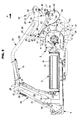
- the displacement device (24) can be placed in at least a first position and a second position.
- the first connecting means (25) and the second connecting means (26) are geometrically and / or elastically configured so that in the first position illustrated in FIG. figure 2 the lower end (49) of the guide device (17) is raised substantially above the ground and the intermediate portion (52) is brought closer to the tines (9) of the pickup device (2), and that in the second position represented in the figure 6 , the lower end (49) is very close to the ground and that the intermediate portion (52) and the rear portion (50) are away from the tooth tips (9) of the pickup device (2).
- the connecting means (25 and 26) are, in particular in terms of dimensions, shape and positioning of the joints to the guiding device (17) and the structure (22), configured to obtain the first and second positions as previously described.
- elastically is meant that the connecting means (25 and 26) have a capacity to elastically deform depending on their dimensional characteristics and the intrinsic properties of the (x) material (x) which compose them (nt) .
- the rear end (51) of the guide device (17) is also close to the tooth tips (9) of the pickup device (2).
- the teeth (8) penetrate the flow of vegetation and drag it over the entire extent of the guide device (17) above the pickup device (2).
- the main instantaneous center of rotation (27) is located in the vicinity of the rear end (51) of the guiding device (17).
- the guide device (17) pivots substantially around its rear end (51) so as to adjust the orientation of the rear portion (50) relative to the device treatment (3).
- the rear part (50) of the guiding device (17) preferably extends substantially parallel to the upper casing (16) of the treatment device (3), that is to say, in the embodiments of the figures, substantially parallel to the upper surface of the strip (14) which composes it.
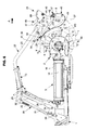
- figure 3 shows that when the guiding device (17) moves somewhat away from the first position ( figure 2 ), its rear portion (50) inclines with respect to said strip (14).
- the main instantaneous center of rotation (27) moves along a first curve portion (53) located inside the curved envelope (10) described by the tips of teeth (9). It appears in fact that in the intermediate positions of the guiding device (17) illustrated in FIGS. figures 3 and 4 , the main instantaneous center of rotation (27) is on this first portion of curve (53) delimited by the points of intersection (a) and (b) with said curved envelope (10). In this way, when the main instantaneous center of rotation (27) moves along the first curve portion (53), the intermediate portion (52) of the guiding device (17) moves along the said curved envelope (10) and is substantially tangential to the latter.
- the section of passage of plants between the guide device (17) and the guide surface (4) therefore remains substantially constant, and the plants remain in good contact with the teeth (8). Plants are routinely routed to the treatment device (3) without the risk of formation of packets or jams.
- the adjustment of the guiding device (17) in the positions of the figures 3 and 4 is particularly suitable for medium density forage conditions or having a certain mixture of short and long strands. Indeed, during the displacement of the main instantaneous center of rotation (27) along the first curve portion (53), the rear portion (50) of the guiding device (17) sees its inclination vary with respect to the upper casing (16) of the treatment device (3). This makes it possible to project the plants at the optimal location on the treatment device (3). At the same time, the front portion (48) extends to a greater or lesser height of the ground. The user thus has the possibility of reducing more or less the tendency of the plants to be projected ahead of the collecting device (2).
- the main instantaneous center of rotation (27) is located in the vicinity of the lower end (49) of the guide device (17).
- the movement of the guiding device (17) from the first to the second position ends with a substantially pivotal movement about the lower end (49) whose height relative to the ground has reached a minimum.
- the intermediate portion (52) and the rear portion (50) are remote from the tooth tips (9) of the pickup device (2).
- the intermediate portion (52) is preferably away from the tooth tips (9) by about twice the distance between the tooth tips (9) and the guide surface (4).
- the section of passage of plants downstream of the lower end (49) is important, which allows light or short-stranded plants to acquire a high speed at their output of the collection device (2).
- the rear portion (50) of the guiding device (17) forms with the upper casing (16) of the treatment device (3) an angle ( ⁇ ) of between 10 ° and 45 °. Plants, projected at high speed and obliquely to the treatment device (3), and fall on the latter at the optimum location.
- the rear end (51) of the guiding device (17) is located, relative to the direction of advance (A), in front of the upper end (11) of the guide surface (4). In this way, the plants are not braked or folded towards the treatment device (3) when they begin to be released by the teeth (8) behind said upper end (11).
- the main instantaneous center of rotation (27) moves along a second curve portion (54) inclined towards the ground in the direction d advancement (A) of the machine.
- the main instantaneous center of rotation (27) is located on this second curve portion (54) delimited by the points (c) and (d).
- the comparison of these figures shows that during the displacement of the position of the figure 4 towards that of the figure 5 the intermediate portion (52) of the guiding device (17) begins to move away from the tooth tips (9) while the lower end (49) is situated at a distance from the ground close to the minimum reached in the second position. In this way, a smooth transition is achieved between the movement of the guiding device (17) along the tooth tips (9) and the final pivoting movement around the lower end (49).
- first curve portion (53) and the second curve portion (54) are preferably at least partially merged. Indeed, point (c) is higher than point (b).
- the displacement device (24) is configured such that in the first position, the lower end (49) of the guide device (17) is at a substantial height of the ground, for example to pass over a windrow of high volume.
- Such clearance is advantageously obtained by the fact that, in this first position, the lower end (49) of the guiding device (17) lies between a first horizontal plane (P1) passing through the axis of rotation (6). ) of the rotor (5) and a second horizontal plane (P2) passing through the upper end (11) of the guide surface (4).
- the lower end (49) is close to the ground. To this end, it is located, in this second position, between the first horizontal plane (P1) passing through the axis of rotation (6) of the rotor (5) and a third horizontal plane (P3) passing through the low end (12) of the guide surface (4).
- the displacement device (24) can be maintained in the first and second positions by means of a direct or remote control device (55).
- the adjustment device (55) is directly controlled.
- One of the arms (23) carries a sector (56) having notches or holes.
- this sector (56) supports the connecting rod (40) located at the front of the guiding device (17).
- This rod (40) is integral with a control lever (57) that the user can position in one of the notches or holes provided on the sector (56), in order to place the guide device (17) in the different positions.
- the presence of several notches or holes is that in addition, the displacement device (24) can be maintained by means of said adjusting device (55) in at least one intermediate position between the first and second positions.
- control lever (57) is connected to the bar (21) of the guide device (17) by means of a return lever which converts a pivoting of the control lever (57) into a displacement of the first and second axes (45 and 47) within their respective first and second guide paths (44 and 46).
- a direct command such as the one just described can be substituted for a remote command.
- This comprises for example a cylinder, in particular hydraulic, electric or pneumatic, articulated between the arm (23) and the displacement device (24) or the guiding device (17).
- This jack can be actuated from a control unit permanently placed on the machine, for example on a part of the frame (1), or remote in the cab of the tractor to which the machine is coupled.
- the direct drive may include a motor, including hydraulic or electric.
- the stator of such a motor is fixed on the arm (23) while its rotor is connected to an axis of articulation of one of the connecting rods (36 and 40) to the structure (22).
- a remote control such as those mentioned by way of example, makes it easy to move and maintain the displacement device (24) in the first and second positions as well as in any intermediate position.
- setting device (55) direct control or remote remain possible.
Landscapes
- Life Sciences & Earth Sciences (AREA)
- Environmental Sciences (AREA)
- Soil Working Implements (AREA)
- Harvesting Machines For Root Crops (AREA)
- Apparatuses For Bulk Treatment Of Fruits And Vegetables And Apparatuses For Preparing Feeds (AREA)
Priority Applications (2)
| Application Number | Priority Date | Filing Date | Title |
|---|---|---|---|
| SI201330103T SI2745672T1 (sl) | 2012-12-20 | 2013-12-09 | Kmetijski setveni stroj, ki obsega izboljšano napravo za vodenje rastlin |
| PL13306686T PL2745672T3 (pl) | 2012-12-20 | 2013-12-09 | Maszyna rolnicza do zbierania plonu z ulepszonym urządzeniem naprowadzania roślin |
Applications Claiming Priority (1)
| Application Number | Priority Date | Filing Date | Title |
|---|---|---|---|
| FR1262381A FR2999868B1 (fr) | 2012-12-20 | 2012-12-20 | Machine agricole de recolte comportant un dispositif de guidage perfectionne des vegetaux |
Publications (2)
| Publication Number | Publication Date |
|---|---|
| EP2745672A1 EP2745672A1 (fr) | 2014-06-25 |
| EP2745672B1 true EP2745672B1 (fr) | 2015-09-09 |
Family
ID=47882287
Family Applications (1)
| Application Number | Title | Priority Date | Filing Date |
|---|---|---|---|
| EP13306686.0A Active EP2745672B1 (fr) | 2012-12-20 | 2013-12-09 | Machine agricole de récolte comportant un dispositif de guidage perfectionné des végétaux |
Country Status (7)
| Country | Link |
|---|---|
| US (1) | US9192102B2 (pl) |
| EP (1) | EP2745672B1 (pl) |
| DK (1) | DK2745672T3 (pl) |
| ES (1) | ES2555296T3 (pl) |
| FR (1) | FR2999868B1 (pl) |
| PL (1) | PL2745672T3 (pl) |
| SI (1) | SI2745672T1 (pl) |
Cited By (1)
| Publication number | Priority date | Publication date | Assignee | Title |
|---|---|---|---|---|
| EP4066624B1 (en) * | 2021-03-31 | 2026-02-25 | CNH Industrial Belgium N.V. | Agricultural vehicle with independently movable windguard rollers |
Families Citing this family (8)
| Publication number | Priority date | Publication date | Assignee | Title |
|---|---|---|---|---|
| US9521807B2 (en) * | 2014-05-05 | 2016-12-20 | Roc S.R.L. | Guiding unit for a device for harvesting the long agricultural products and device for harvesting agricultural products comprising the guiding unit |
| US12063892B2 (en) * | 2019-08-15 | 2024-08-20 | Kuhn North America, Inc. | Systems, apparatus, and related methods for use with mergers |
| US12089536B2 (en) * | 2020-05-19 | 2024-09-17 | Cnh Industrial America Llc | Agricultural vehicle with retainer for blockage removing windguard |
| NL2026328B1 (nl) * | 2020-08-24 | 2022-04-14 | Ploeger Oxbo Europe B V | Inrichting die verplaatsbaar is in een rijrichting over land, waarbij de inrichting is voorzien van ten minste een oppakmechanisme voor het oppakken van product van het land, alsmede van ten minste een transportband |
| FR3133969B1 (fr) * | 2022-04-05 | 2024-05-17 | N V Depoortere | Dispositif de ramassage d’andains de tiges végétales ayant une roue de ramassage à doigts fixes. |
| PL246847B1 (pl) * | 2022-10-28 | 2025-03-17 | Samasz Spolka Z Ograniczona Odpowiedzialnoscia | Maszyna rolnicza, zwłaszcza do zbierania pokosów traw i innych roślin |
| ES3037929T3 (en) * | 2022-12-01 | 2025-10-08 | Roc S R L | Windrow merger and method for forming windrows through a windrow merger which collects agricultural products from a field |
| CN117882566B (zh) * | 2024-01-25 | 2024-08-27 | 济宁圣地农林机械有限公司 | 一种方捆捡拾机 |
Family Cites Families (31)
| Publication number | Priority date | Publication date | Assignee | Title |
|---|---|---|---|---|
| US2524233A (en) * | 1941-04-19 | 1950-10-03 | Case Co J I | Pickup device for balers |
| US2362861A (en) * | 1941-04-19 | 1944-11-14 | Case Co J I | Baler |
| US2571489A (en) * | 1944-06-16 | 1951-10-16 | Case Co J I | Baling machine with spiral feeding and compression means |
| US2647355A (en) * | 1949-03-05 | 1953-08-04 | Massey Harris Co Ltd | Pickup baler |
| US2872772A (en) * | 1951-10-30 | 1959-02-10 | Sperry Rand Corp | Adjustable wind-guard for baler pick-up |
| US2691266A (en) * | 1953-03-23 | 1954-10-12 | Volk | Wind guard attachment for pickup devices |
| US3815344A (en) * | 1972-11-29 | 1974-06-11 | Lowell R | Machine for forming large round bales of a fibrous material |
| US3815346A (en) * | 1973-06-01 | 1974-06-11 | Deere & Co | Harvester pickup |
| US3924391A (en) | 1975-03-03 | 1975-12-09 | Deere & Co | Adjustable crop compressor for a pickup mechanism |
| DD139380A1 (de) * | 1978-06-20 | 1980-01-02 | Spaida Hans Peter | Aufnahmeeinrichtung fuer halmfuttererntemaschinen |
| US4304090A (en) * | 1980-02-11 | 1981-12-08 | Gavrilenko Boris P | Pickup of an agricultural machine |
| NL8003794A (nl) * | 1980-07-01 | 1982-02-01 | Multinorm Bv | Inrichting voor het van het land opnemen van gewas. |
| US4411127A (en) * | 1982-04-05 | 1983-10-25 | Sperry Corporation | Floating windguard |
| US4495756A (en) * | 1983-08-15 | 1985-01-29 | Sperry Corporation | Pickup attachment for harvesting machines |
| US4516389A (en) * | 1984-09-04 | 1985-05-14 | Core Grant M | Round hay baling machine |
| US4981013A (en) * | 1989-08-21 | 1991-01-01 | Underwood Chester E | Corn harvesting apparatus |
| GB9903624D0 (en) * | 1999-02-18 | 1999-04-07 | Ford New Holland Nv | Movable windguard |
| US6688092B2 (en) * | 2002-01-14 | 2004-02-10 | Deere & Company | Pick-up crop baffle including integral crop hold down rods and suspension for use in widely varied crops |
| US6810650B2 (en) * | 2002-03-28 | 2004-11-02 | New Holland North America, Inc. | Replaceable windguard tines for a round baler |
| US6935094B1 (en) * | 2004-04-15 | 2005-08-30 | Cnh America Llc | Wind guard latch retainer |
| US7107748B2 (en) * | 2004-07-31 | 2006-09-19 | Cnh America Llc | Agricultural implement pickup |
| US6962041B1 (en) * | 2004-07-31 | 2005-11-08 | Cnh America Llc | Windguard for round baler including float arms |
| US6877304B1 (en) * | 2004-07-31 | 2005-04-12 | Cnh America Llc | Windguard for round baler |
| US20060277889A1 (en) * | 2005-06-10 | 2006-12-14 | Sheedy Ronald L | Wind screen hold down attachment |
| US7617662B2 (en) * | 2005-06-14 | 2009-11-17 | Deere & Company | Integrated crop baffle and hold-down assembly used with baler pick-up and suspension for same |
| FR2898243B1 (fr) * | 2006-03-10 | 2008-05-09 | Idass Sa | Engin agricole ramasseur d'andains |
| FR2902963B1 (fr) * | 2006-06-30 | 2010-05-07 | Kuhn Sa | Machine agricole pour la recolte des fourrages, comportant des dispositifs de ramassage et de deplacement des vegetaux |
| US7448196B2 (en) * | 2007-01-05 | 2008-11-11 | Agco Corporation | Baler with multi-auger pickup |
| US20090100814A1 (en) * | 2007-10-22 | 2009-04-23 | Philip Egging | Non-Powered Roller for Assisting Crop Pick-Up With a Baler |
| US7654069B1 (en) * | 2008-12-10 | 2010-02-02 | Vermeer Manufacturing Co. | Baler slider frame for mounting accessories to a crop pickup device |
| US8051634B2 (en) * | 2010-01-19 | 2011-11-08 | Cnh America Llc | Replaceable guide assembly tines for an agricultural harvester |
-
2012
- 2012-12-20 FR FR1262381A patent/FR2999868B1/fr not_active Expired - Fee Related
-
2013
- 2013-12-06 US US14/098,869 patent/US9192102B2/en active Active
- 2013-12-09 DK DK13306686.0T patent/DK2745672T3/en active
- 2013-12-09 EP EP13306686.0A patent/EP2745672B1/fr active Active
- 2013-12-09 SI SI201330103T patent/SI2745672T1/sl unknown
- 2013-12-09 PL PL13306686T patent/PL2745672T3/pl unknown
- 2013-12-09 ES ES13306686.0T patent/ES2555296T3/es active Active
Cited By (1)
| Publication number | Priority date | Publication date | Assignee | Title |
|---|---|---|---|---|
| EP4066624B1 (en) * | 2021-03-31 | 2026-02-25 | CNH Industrial Belgium N.V. | Agricultural vehicle with independently movable windguard rollers |
Also Published As
| Publication number | Publication date |
|---|---|
| FR2999868A1 (fr) | 2014-06-27 |
| US9192102B2 (en) | 2015-11-24 |
| PL2745672T3 (pl) | 2016-03-31 |
| ES2555296T3 (es) | 2015-12-30 |
| SI2745672T1 (sl) | 2016-01-29 |
| DK2745672T3 (en) | 2015-12-21 |
| FR2999868B1 (fr) | 2014-12-12 |
| EP2745672A1 (fr) | 2014-06-25 |
| US20140174051A1 (en) | 2014-06-26 |
Similar Documents
| Publication | Publication Date | Title |
|---|---|---|
| EP2745672B1 (fr) | Machine agricole de récolte comportant un dispositif de guidage perfectionné des végétaux | |
| EP2929774B1 (fr) | Machine pour la récolte de fourrage présentant un déflecteur perfectionné | |
| EP2037727B1 (fr) | Machine agricole pour la recolte des fourrages | |
| EP2839731B1 (fr) | Machine de récolte de fourrage | |
| EP2756749A1 (fr) | Machine de fenaison comportant un déflecteur perfectionné | |
| EP1684569B1 (fr) | Machine agricole pour l'andainage de produits se trouvant au sol | |
| EP2731414B1 (fr) | Dispositif de ramassage articulé et machine agricole equipée d'un tel dispositif | |
| EP1605748B1 (fr) | Machine pour grouper des produits tels que de l'herbe | |
| EP0332552A1 (fr) | Perfectionnement aux machines agricoles pour la récolte | |
| EP2720528B1 (fr) | Machine a tirer automatiquement les sarments de vigne tailles | |
| FR3007240A1 (fr) | Machine de recolte comportant un asservissement de la hauteur de relevage d'un outil de recolte | |
| FR2916604A1 (fr) | Structure porteuse pour retourneuse d'andains | |
| FR2916603A1 (fr) | Engin de retournage d'andain | |
| WO2019211229A1 (fr) | Machine agricole pour la recolte de vegetaux equipee d'un convoyeur | |
| EP4042857A1 (fr) | Machine agricole du type faucheuse | |
| FR2686481A1 (fr) | Machine de fenaison comportant un chassis avec des roues porteuses commandees. | |
| EP4035522B1 (fr) | Machine de fenaison comportant un dispositif de déplacement transversal de récolte | |
| FR2839611A1 (fr) | Dispositif de capture, de guidage et de relevage de fils de palissage d'une vegetation palissee | |
| EP2526750A1 (fr) | Machine de fenaison | |
| EP2599376B1 (fr) | Machine de fenaison | |
| FR2487159A1 (fr) | Machine pour recolter les plantes en touffes | |
| EP0065052A1 (fr) | Presse à balles tandem | |
| WO1997000604A1 (fr) | Machine perfectionnee pour ligaturer automatiquement les sarments de vigne sur un fil tendu | |
| FR2558030A1 (fr) | Machine pour ramasser et former en balles rondes des matieres fibreuses disposees en andains | |
| BE534545A (pl) |
Legal Events
| Date | Code | Title | Description |
|---|---|---|---|
| PUAI | Public reference made under article 153(3) epc to a published international application that has entered the european phase |
Free format text: ORIGINAL CODE: 0009012 |
|
| 17P | Request for examination filed |
Effective date: 20131209 |
|
| AK | Designated contracting states |
Kind code of ref document: A1 Designated state(s): AL AT BE BG CH CY CZ DE DK EE ES FI FR GB GR HR HU IE IS IT LI LT LU LV MC MK MT NL NO PL PT RO RS SE SI SK SM TR |
|
| AX | Request for extension of the european patent |
Extension state: BA ME |
|
| R17P | Request for examination filed (corrected) |
Effective date: 20141009 |
|
| RBV | Designated contracting states (corrected) |
Designated state(s): AL AT BE BG CH CY CZ DE DK EE ES FI FR GB GR HR HU IE IS IT LI LT LU LV MC MK MT NL NO PL PT RO RS SE SI SK SM TR |
|
| GRAP | Despatch of communication of intention to grant a patent |
Free format text: ORIGINAL CODE: EPIDOSNIGR1 |
|
| INTG | Intention to grant announced |
Effective date: 20150324 |
|
| GRAS | Grant fee paid |
Free format text: ORIGINAL CODE: EPIDOSNIGR3 |
|
| GRAA | (expected) grant |
Free format text: ORIGINAL CODE: 0009210 |
|
| AK | Designated contracting states |
Kind code of ref document: B1 Designated state(s): AL AT BE BG CH CY CZ DE DK EE ES FI FR GB GR HR HU IE IS IT LI LT LU LV MC MK MT NL NO PL PT RO RS SE SI SK SM TR |
|
| REG | Reference to a national code |
Ref country code: GB Ref legal event code: FG4D Free format text: NOT ENGLISH |
|
| REG | Reference to a national code |
Ref country code: AT Ref legal event code: REF Ref document number: 747315 Country of ref document: AT Kind code of ref document: T Effective date: 20150915 Ref country code: CH Ref legal event code: EP |
|
| REG | Reference to a national code |
Ref country code: IE Ref legal event code: FG4D Free format text: LANGUAGE OF EP DOCUMENT: FRENCH |
|
| REG | Reference to a national code |
Ref country code: DE Ref legal event code: R096 Ref document number: 602013002946 Country of ref document: DE |
|
| REG | Reference to a national code |
Ref country code: FR Ref legal event code: PLFP Year of fee payment: 3 |
|
| REG | Reference to a national code |
Ref country code: DK Ref legal event code: T3 Effective date: 20151215 |
|
| REG | Reference to a national code |
Ref country code: ES Ref legal event code: FG2A Ref document number: 2555296 Country of ref document: ES Kind code of ref document: T3 Effective date: 20151230 |
|
| PG25 | Lapsed in a contracting state [announced via postgrant information from national office to epo] |
Ref country code: LT Free format text: LAPSE BECAUSE OF FAILURE TO SUBMIT A TRANSLATION OF THE DESCRIPTION OR TO PAY THE FEE WITHIN THE PRESCRIBED TIME-LIMIT Effective date: 20150909 Ref country code: GR Free format text: LAPSE BECAUSE OF FAILURE TO SUBMIT A TRANSLATION OF THE DESCRIPTION OR TO PAY THE FEE WITHIN THE PRESCRIBED TIME-LIMIT Effective date: 20151210 Ref country code: FI Free format text: LAPSE BECAUSE OF FAILURE TO SUBMIT A TRANSLATION OF THE DESCRIPTION OR TO PAY THE FEE WITHIN THE PRESCRIBED TIME-LIMIT Effective date: 20150909 Ref country code: LV Free format text: LAPSE BECAUSE OF FAILURE TO SUBMIT A TRANSLATION OF THE DESCRIPTION OR TO PAY THE FEE WITHIN THE PRESCRIBED TIME-LIMIT Effective date: 20150909 Ref country code: NO Free format text: LAPSE BECAUSE OF FAILURE TO SUBMIT A TRANSLATION OF THE DESCRIPTION OR TO PAY THE FEE WITHIN THE PRESCRIBED TIME-LIMIT Effective date: 20151209 |
|
| REG | Reference to a national code |
Ref country code: LT Ref legal event code: MG4D Ref country code: NL Ref legal event code: FP |
|
| PG25 | Lapsed in a contracting state [announced via postgrant information from national office to epo] |
Ref country code: HR Free format text: LAPSE BECAUSE OF FAILURE TO SUBMIT A TRANSLATION OF THE DESCRIPTION OR TO PAY THE FEE WITHIN THE PRESCRIBED TIME-LIMIT Effective date: 20150909 Ref country code: SE Free format text: LAPSE BECAUSE OF FAILURE TO SUBMIT A TRANSLATION OF THE DESCRIPTION OR TO PAY THE FEE WITHIN THE PRESCRIBED TIME-LIMIT Effective date: 20150909 Ref country code: RS Free format text: LAPSE BECAUSE OF FAILURE TO SUBMIT A TRANSLATION OF THE DESCRIPTION OR TO PAY THE FEE WITHIN THE PRESCRIBED TIME-LIMIT Effective date: 20150909 |
|
| PG25 | Lapsed in a contracting state [announced via postgrant information from national office to epo] |
Ref country code: SK Free format text: LAPSE BECAUSE OF FAILURE TO SUBMIT A TRANSLATION OF THE DESCRIPTION OR TO PAY THE FEE WITHIN THE PRESCRIBED TIME-LIMIT Effective date: 20150909 Ref country code: EE Free format text: LAPSE BECAUSE OF FAILURE TO SUBMIT A TRANSLATION OF THE DESCRIPTION OR TO PAY THE FEE WITHIN THE PRESCRIBED TIME-LIMIT Effective date: 20150909 Ref country code: IS Free format text: LAPSE BECAUSE OF FAILURE TO SUBMIT A TRANSLATION OF THE DESCRIPTION OR TO PAY THE FEE WITHIN THE PRESCRIBED TIME-LIMIT Effective date: 20160109 |
|
| PG25 | Lapsed in a contracting state [announced via postgrant information from national office to epo] |
Ref country code: RO Free format text: LAPSE BECAUSE OF FAILURE TO SUBMIT A TRANSLATION OF THE DESCRIPTION OR TO PAY THE FEE WITHIN THE PRESCRIBED TIME-LIMIT Effective date: 20150909 Ref country code: PT Free format text: LAPSE BECAUSE OF FAILURE TO SUBMIT A TRANSLATION OF THE DESCRIPTION OR TO PAY THE FEE WITHIN THE PRESCRIBED TIME-LIMIT Effective date: 20160111 Ref country code: BE Free format text: LAPSE BECAUSE OF NON-PAYMENT OF DUE FEES Effective date: 20151231 |
|
| REG | Reference to a national code |
Ref country code: DE Ref legal event code: R097 Ref document number: 602013002946 Country of ref document: DE |
|
| PLBE | No opposition filed within time limit |
Free format text: ORIGINAL CODE: 0009261 |
|
| STAA | Information on the status of an ep patent application or granted ep patent |
Free format text: STATUS: NO OPPOSITION FILED WITHIN TIME LIMIT |
|
| PG25 | Lapsed in a contracting state [announced via postgrant information from national office to epo] |
Ref country code: LU Free format text: LAPSE BECAUSE OF FAILURE TO SUBMIT A TRANSLATION OF THE DESCRIPTION OR TO PAY THE FEE WITHIN THE PRESCRIBED TIME-LIMIT Effective date: 20151209 Ref country code: MC Free format text: LAPSE BECAUSE OF FAILURE TO SUBMIT A TRANSLATION OF THE DESCRIPTION OR TO PAY THE FEE WITHIN THE PRESCRIBED TIME-LIMIT Effective date: 20150909 |
|
| 26N | No opposition filed |
Effective date: 20160610 |
|
| REG | Reference to a national code |
Ref country code: IE Ref legal event code: MM4A |
|
| PG25 | Lapsed in a contracting state [announced via postgrant information from national office to epo] |
Ref country code: IE Free format text: LAPSE BECAUSE OF NON-PAYMENT OF DUE FEES Effective date: 20151209 |
|
| REG | Reference to a national code |
Ref country code: FR Ref legal event code: PLFP Year of fee payment: 4 |
|
| PG25 | Lapsed in a contracting state [announced via postgrant information from national office to epo] |
Ref country code: BG Free format text: LAPSE BECAUSE OF FAILURE TO SUBMIT A TRANSLATION OF THE DESCRIPTION OR TO PAY THE FEE WITHIN THE PRESCRIBED TIME-LIMIT Effective date: 20150909 Ref country code: HU Free format text: LAPSE BECAUSE OF FAILURE TO SUBMIT A TRANSLATION OF THE DESCRIPTION OR TO PAY THE FEE WITHIN THE PRESCRIBED TIME-LIMIT; INVALID AB INITIO Effective date: 20131209 |
|
| PG25 | Lapsed in a contracting state [announced via postgrant information from national office to epo] |
Ref country code: CY Free format text: LAPSE BECAUSE OF FAILURE TO SUBMIT A TRANSLATION OF THE DESCRIPTION OR TO PAY THE FEE WITHIN THE PRESCRIBED TIME-LIMIT Effective date: 20150909 |
|
| REG | Reference to a national code |
Ref country code: CH Ref legal event code: PL |
|
| PG25 | Lapsed in a contracting state [announced via postgrant information from national office to epo] |
Ref country code: MT Free format text: LAPSE BECAUSE OF FAILURE TO SUBMIT A TRANSLATION OF THE DESCRIPTION OR TO PAY THE FEE WITHIN THE PRESCRIBED TIME-LIMIT Effective date: 20150909 |
|
| PG25 | Lapsed in a contracting state [announced via postgrant information from national office to epo] |
Ref country code: LI Free format text: LAPSE BECAUSE OF NON-PAYMENT OF DUE FEES Effective date: 20161231 Ref country code: CH Free format text: LAPSE BECAUSE OF NON-PAYMENT OF DUE FEES Effective date: 20161231 |
|
| REG | Reference to a national code |
Ref country code: FR Ref legal event code: PLFP Year of fee payment: 5 |
|
| REG | Reference to a national code |
Ref country code: AT Ref legal event code: UEP Ref document number: 747315 Country of ref document: AT Kind code of ref document: T Effective date: 20150909 |
|
| PGFP | Annual fee paid to national office [announced via postgrant information from national office to epo] |
Ref country code: CZ Payment date: 20171123 Year of fee payment: 5 Ref country code: NL Payment date: 20171124 Year of fee payment: 5 |
|
| PGFP | Annual fee paid to national office [announced via postgrant information from national office to epo] |
Ref country code: IE Payment date: 20171214 Year of fee payment: 6 |
|
| REG | Reference to a national code |
Ref country code: DE Ref legal event code: R082 Ref document number: 602013002946 Country of ref document: DE Representative=s name: WUNDERLICH & HEIM PATENTANWAELTE PARTNERSCHAFT, DE |
|
| PGFP | Annual fee paid to national office [announced via postgrant information from national office to epo] |
Ref country code: ES Payment date: 20180103 Year of fee payment: 5 |
|
| PG25 | Lapsed in a contracting state [announced via postgrant information from national office to epo] |
Ref country code: SM Free format text: LAPSE BECAUSE OF FAILURE TO SUBMIT A TRANSLATION OF THE DESCRIPTION OR TO PAY THE FEE WITHIN THE PRESCRIBED TIME-LIMIT Effective date: 20150909 |
|
| PG25 | Lapsed in a contracting state [announced via postgrant information from national office to epo] |
Ref country code: MK Free format text: LAPSE BECAUSE OF FAILURE TO SUBMIT A TRANSLATION OF THE DESCRIPTION OR TO PAY THE FEE WITHIN THE PRESCRIBED TIME-LIMIT Effective date: 20150909 |
|
| PG25 | Lapsed in a contracting state [announced via postgrant information from national office to epo] |
Ref country code: AL Free format text: LAPSE BECAUSE OF FAILURE TO SUBMIT A TRANSLATION OF THE DESCRIPTION OR TO PAY THE FEE WITHIN THE PRESCRIBED TIME-LIMIT Effective date: 20150909 Ref country code: TR Free format text: LAPSE BECAUSE OF FAILURE TO SUBMIT A TRANSLATION OF THE DESCRIPTION OR TO PAY THE FEE WITHIN THE PRESCRIBED TIME-LIMIT Effective date: 20150909 |
|
| PG25 | Lapsed in a contracting state [announced via postgrant information from national office to epo] |
Ref country code: CZ Free format text: LAPSE BECAUSE OF NON-PAYMENT OF DUE FEES Effective date: 20181209 |
|
| REG | Reference to a national code |
Ref country code: NL Ref legal event code: MM Effective date: 20190101 |
|
| GBPC | Gb: european patent ceased through non-payment of renewal fee |
Effective date: 20181209 |
|
| PG25 | Lapsed in a contracting state [announced via postgrant information from national office to epo] |
Ref country code: NL Free format text: LAPSE BECAUSE OF NON-PAYMENT OF DUE FEES Effective date: 20190101 |
|
| PG25 | Lapsed in a contracting state [announced via postgrant information from national office to epo] |
Ref country code: GB Free format text: LAPSE BECAUSE OF NON-PAYMENT OF DUE FEES Effective date: 20181209 |
|
| REG | Reference to a national code |
Ref country code: ES Ref legal event code: FD2A Effective date: 20200131 |
|
| PG25 | Lapsed in a contracting state [announced via postgrant information from national office to epo] |
Ref country code: ES Free format text: LAPSE BECAUSE OF NON-PAYMENT OF DUE FEES Effective date: 20181210 |
|
| PGFP | Annual fee paid to national office [announced via postgrant information from national office to epo] |
Ref country code: SI Payment date: 20231121 Year of fee payment: 11 Ref country code: IT Payment date: 20231220 Year of fee payment: 11 Ref country code: DK Payment date: 20231229 Year of fee payment: 11 Ref country code: AT Payment date: 20231121 Year of fee payment: 11 |
|
| PGFP | Annual fee paid to national office [announced via postgrant information from national office to epo] |
Ref country code: PL Payment date: 20231120 Year of fee payment: 11 |
|
| PGFP | Annual fee paid to national office [announced via postgrant information from national office to epo] |
Ref country code: DE Payment date: 20241227 Year of fee payment: 12 |
|
| REG | Reference to a national code |
Ref country code: DK Ref legal event code: EBP Effective date: 20241231 |
|
| REG | Reference to a national code |
Ref country code: AT Ref legal event code: MM01 Ref document number: 747315 Country of ref document: AT Kind code of ref document: T Effective date: 20241209 |
|
| REG | Reference to a national code |
Ref country code: SI Ref legal event code: KO00 Effective date: 20241210 |
|
| PG25 | Lapsed in a contracting state [announced via postgrant information from national office to epo] |
Ref country code: IT Free format text: LAPSE BECAUSE OF NON-PAYMENT OF DUE FEES Effective date: 20241209 |
|
| PG25 | Lapsed in a contracting state [announced via postgrant information from national office to epo] |
Ref country code: AT Free format text: LAPSE BECAUSE OF NON-PAYMENT OF DUE FEES Effective date: 20241209 |
|
| PG25 | Lapsed in a contracting state [announced via postgrant information from national office to epo] |
Ref country code: DK Free format text: LAPSE BECAUSE OF NON-PAYMENT OF DUE FEES Effective date: 20241231 |
|
| PGFP | Annual fee paid to national office [announced via postgrant information from national office to epo] |
Ref country code: FR Payment date: 20251226 Year of fee payment: 13 |