EP2745274B1 - Vorrichtung zur betätigung einer tür oder klappe an einem fahrzeug - Google Patents
Vorrichtung zur betätigung einer tür oder klappe an einem fahrzeug Download PDFInfo
- Publication number
- EP2745274B1 EP2745274B1 EP11782377.3A EP11782377A EP2745274B1 EP 2745274 B1 EP2745274 B1 EP 2745274B1 EP 11782377 A EP11782377 A EP 11782377A EP 2745274 B1 EP2745274 B1 EP 2745274B1
- Authority
- EP
- European Patent Office
- Prior art keywords
- coaxial cable
- insulating layer
- metallic
- sensor
- sheath
- Prior art date
- Legal status (The legal status is an assumption and is not a legal conclusion. Google has not performed a legal analysis and makes no representation as to the accuracy of the status listed.)
- Active
Links
Images


Classifications
-
- H—ELECTRICITY
- H01—ELECTRIC ELEMENTS
- H01B—CABLES; CONDUCTORS; INSULATORS; SELECTION OF MATERIALS FOR THEIR CONDUCTIVE, INSULATING OR DIELECTRIC PROPERTIES
- H01B11/00—Communication cables or conductors
- H01B11/18—Coaxial cables; Analogous cables having more than one inner conductor within a common outer conductor
- H01B11/1834—Construction of the insulation between the conductors
-
- B—PERFORMING OPERATIONS; TRANSPORTING
- B60—VEHICLES IN GENERAL
- B60R—VEHICLES, VEHICLE FITTINGS, OR VEHICLE PARTS, NOT OTHERWISE PROVIDED FOR
- B60R19/00—Wheel guards; Radiator guards, e.g. grilles; Obstruction removers; Fittings damping bouncing force in collisions
- B60R19/02—Bumpers, i.e. impact receiving or absorbing members for protecting vehicles or fending off blows from other vehicles or objects
- B60R19/48—Bumpers, i.e. impact receiving or absorbing members for protecting vehicles or fending off blows from other vehicles or objects combined with, or convertible into, other devices or objects, e.g. bumpers combined with road brushes, bumpers convertible into beds
- B60R19/483—Bumpers, i.e. impact receiving or absorbing members for protecting vehicles or fending off blows from other vehicles or objects combined with, or convertible into, other devices or objects, e.g. bumpers combined with road brushes, bumpers convertible into beds with obstacle sensors of electric or electronic type
-
- E—FIXED CONSTRUCTIONS
- E05—LOCKS; KEYS; WINDOW OR DOOR FITTINGS; SAFES
- E05B—LOCKS; ACCESSORIES THEREFOR; HANDCUFFS
- E05B83/00—Vehicle locks specially adapted for particular types of wing or vehicle
- E05B83/16—Locks for luggage compartments, car boot lids or car bonnets
- E05B83/18—Locks for luggage compartments, car boot lids or car bonnets for car boot lids or rear luggage compartments
-
- E—FIXED CONSTRUCTIONS
- E05—LOCKS; KEYS; WINDOW OR DOOR FITTINGS; SAFES
- E05B—LOCKS; ACCESSORIES THEREFOR; HANDCUFFS
- E05B85/00—Details of vehicle locks not provided for in groups E05B77/00 - E05B83/00
- E05B85/01—Mechanical arrangements specially adapted for hands-free locking or unlocking
-
- E—FIXED CONSTRUCTIONS
- E05—LOCKS; KEYS; WINDOW OR DOOR FITTINGS; SAFES
- E05F—DEVICES FOR MOVING WINGS INTO OPEN OR CLOSED POSITION; CHECKS FOR WINGS; WING FITTINGS NOT OTHERWISE PROVIDED FOR, CONCERNED WITH THE FUNCTIONING OF THE WING
- E05F15/00—Power-operated mechanisms for wings
- E05F15/70—Power-operated mechanisms for wings with automatic actuation
- E05F15/73—Power-operated mechanisms for wings with automatic actuation responsive to movement or presence of persons or objects
- E05F15/76—Power-operated mechanisms for wings with automatic actuation responsive to movement or presence of persons or objects responsive to devices carried by persons or objects, e.g. magnets or reflectors
-
- G—PHYSICS
- G07—CHECKING-DEVICES
- G07C—TIME OR ATTENDANCE REGISTERS; REGISTERING OR INDICATING THE WORKING OF MACHINES; GENERATING RANDOM NUMBERS; VOTING OR LOTTERY APPARATUS; ARRANGEMENTS, SYSTEMS OR APPARATUS FOR CHECKING NOT PROVIDED FOR ELSEWHERE
- G07C9/00—Individual registration on entry or exit
- G07C9/00174—Electronically operated locks; Circuits therefor; Nonmechanical keys therefor, e.g. passive or active electrical keys or other data carriers without mechanical keys
- G07C9/00309—Electronically operated locks; Circuits therefor; Nonmechanical keys therefor, e.g. passive or active electrical keys or other data carriers without mechanical keys operated with bidirectional data transmission between data carrier and locks
-
- G—PHYSICS
- G07—CHECKING-DEVICES
- G07C—TIME OR ATTENDANCE REGISTERS; REGISTERING OR INDICATING THE WORKING OF MACHINES; GENERATING RANDOM NUMBERS; VOTING OR LOTTERY APPARATUS; ARRANGEMENTS, SYSTEMS OR APPARATUS FOR CHECKING NOT PROVIDED FOR ELSEWHERE
- G07C9/00—Individual registration on entry or exit
- G07C9/20—Individual registration on entry or exit involving the use of a pass
- G07C9/28—Individual registration on entry or exit involving the use of a pass the pass enabling tracking or indicating presence
-
- E—FIXED CONSTRUCTIONS
- E05—LOCKS; KEYS; WINDOW OR DOOR FITTINGS; SAFES
- E05B—LOCKS; ACCESSORIES THEREFOR; HANDCUFFS
- E05B53/00—Operation or control of locks by mechanical transmissions, e.g. from a distance
- E05B53/001—Foot-operation
-
- G—PHYSICS
- G07—CHECKING-DEVICES
- G07C—TIME OR ATTENDANCE REGISTERS; REGISTERING OR INDICATING THE WORKING OF MACHINES; GENERATING RANDOM NUMBERS; VOTING OR LOTTERY APPARATUS; ARRANGEMENTS, SYSTEMS OR APPARATUS FOR CHECKING NOT PROVIDED FOR ELSEWHERE
- G07C2209/00—Indexing scheme relating to groups G07C9/00 - G07C9/38
- G07C2209/60—Indexing scheme relating to groups G07C9/00174 - G07C9/00944
- G07C2209/63—Comprising locating means for detecting the position of the data carrier, i.e. within the vehicle or within a certain distance from the vehicle
- G07C2209/65—Comprising locating means for detecting the position of the data carrier, i.e. within the vehicle or within a certain distance from the vehicle using means for sensing the user's hand
-
- H—ELECTRICITY
- H03—ELECTRONIC CIRCUITRY
- H03K—PULSE TECHNIQUE
- H03K17/00—Electronic switching or gating, i.e. not by contact-making and –breaking
- H03K17/94—Electronic switching or gating, i.e. not by contact-making and –breaking characterised by the way in which the control signals are generated
- H03K17/96—Touch switches
- H03K2017/9602—Touch switches characterised by the type or shape of the sensing electrodes
Definitions
- the invention relates to a device for actuating a door or flap of a vehicle, wherein the device has a sensor unit in order to enable detection of an object in at least one detection area adjacent to the motor vehicle, so that the detection of the actuation of the movable part can be activated.
- a sensor unit is known, which is arranged on a bumper.
- the sensor unit is a single-wire electrode, which has a copper wire as the core, which is encased by a plastic layer.
- a disadvantage of such a sensor unit is the low range for detecting the user, which approaches the tailgate.
- the sensor only detects the user just in front of the bumper, so that with a key-free locking system, the tailgate opens very late.
- a coaxial cable is known, which serves as a sensor unit in a motor vehicle seat.
- the inner core of the coaxial cable is designed as a reference conductor element, which serves as a sensor.
- the object of the invention is therefore to provide a device for actuating a door or flap of a vehicle with a sensor unit, which has a greater range for the detection of the user.
- a device according to claim 1 wherein the sensor is formed as a coaxial cable, the first metallic sheath forms the sensor electrode, wherein formed as a metallic core conductor of the coaxial cable has the same electrical potential as the first metallic sheath and active Shield serves.
- the solution according to the invention has the advantage that the range of the sensor unit for detecting the approaching to the tailgate user is increased. As a result, the communication between a vehicle control unit and a radio key of the user is started at an early stage, so that it is already opened when the user approaches the tailgate.
- the conductor of the coaxial cable is at least partially encased by a first insulating layer of the coaxial cable.
- the first insulating layer of the coaxial cable has an ⁇ r , which has a value between 5 and 1.
- the first insulating layer consists of a foamed material having air chambers.
- the first insulating layer consists of air.
- the first insulating layer is at least partially covered by a metallic layer which serves as a sensor electrode.
- the metallic layer is formed as a metal foil and / or wire mesh and / or wire, in particular as a helically wound wire.
- the metallic layer is at least partially encased by a second insulating layer, in particular made of plastic insulating layer, which serves to insulate against external environmental influences, in particular to the metallic portions of the coaxial cable against moisture and corrosion protect.
- the core is formed as a copper wire.
- the senor device is arranged on a bumper.
- the coaxial cable designed as a sensor unit is formed watertight at at least one end.
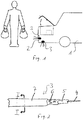
- FIG. 1 a vehicle 1 is shown, which has a bumper 2, in which two sensor units 3 are arranged, wherein the one is aligned with the ground plane and the other is aligned substantially 90 ° offset to the ground plane.
- the user approaches a tailgate of the vehicle.
- the sensor unit 3 detects with the aid of the electric field generated by the sensor unit 3 the user in an adjacent detection area, so that the actuation of the tailgate can be activated via the detection.
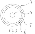
- the sensor unit is shown as a coaxial cable, which has a layered structure.
- the sensor unit 3 is designed as a coaxial cable, wherein the trained as a metallic core conductor 4 of the coaxial cable serves as an active shield.
- the metallic core of the coaxial cable has the same potential as the first metallic sheath.
- the metallic sheath forms the sensor electrode.
- the first metallic sheathing does not act as a sensor electrode to the inside, but reinforced to the outside, ie it is achieved to the outside field amplification.
- the conductor 4 is formed of a copper wire.
- the conductor 4 of the coaxial cable is completely encased by a first insulating layer 5 of the coaxial cable.
- the first insulating layer 5 of the coaxial cable has an ⁇ r , which has a value between 5 and 1.
- the first insulating layer 5 comprises a foamed material having air chambers.
- the first layer 5 preferably comprises polytetrafluoroethylene, alternatively polypropylene or polyethylene. Alternatively, the first insulating layer 5 also consist only of air.
- the first insulating layer 5 is again completely surrounded by a metallic layer 6, which serves as a sensor electrode.
- the sensor electrode builds up an electric field. If the electric field is influenced by a user by the user entering the detection area of the sensor unit, the vehicle control unit is actuated by the sensor unit and initiates the process of opening the tailgate.
- the metallic layer 6 is formed in this embodiment as a metal foil and wire mesh, wherein the wire mesh covers the metal foil.
- the metallic layer can also be formed only as a helically wound wire, which surrounds the first layer 5.
- the metallic layer 6 is completely encased by a second insulating layer 7, which is made of plastic and serves for insulation against external environmental influences in order to protect the metallic parts of the coaxial cable against moisture and corrosion.
- the coaxial cable formed as a sensor unit 3 is formed watertight at one of its ends. The other end of the coaxial cable is used to accommodate a connector.
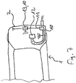
- FIG. 5 is shown as a further embodiment, a coaxial cable having a further metallic sheath, said additional sheath is connected to the ground (ground), so that this sheath serves as a shield of the sensor system to the outside.
- the cable core has the same electrical potential as the first metallic sheath and therefore acts as an active shield to the inside.
- the electric sensor field is amplified to the outside.
- the second metallic sheathing is intended to render the sensor ineffective in the areas where no sensing is necessary or misdetections may occur.
- FIG. 6 the overall system in a vehicle is shown schematically. From a control unit in the vehicle runs the coaxial cable, in this case with second metallic sheath, to the rear area, wherein in the sensor zone on the coaxial cable, the second metallic sheath is removed, so that the Sensor electrode (first metallic sheath) can be effective.
- the end portions of the coaxial cable are insulated to protect against environmental influences.
- the second metallic sheath is connected to ground (electrical, battery) and acts as a shield for the sensor.
- FIG. 7 shows a further embodiment, wherein a plurality of sections of the coaxial cable have no second metallic sheath. This splits the cable into several sensing areas.
- the intermediate portion with second metallic sheath may be connected to ground or without electrical connection.
- the coaxial cable may have a plurality of intermediate sections with and without a second metallic sheath.
Landscapes
- Physics & Mathematics (AREA)
- General Physics & Mathematics (AREA)
- Engineering & Computer Science (AREA)
- Mechanical Engineering (AREA)
- Computer Networks & Wireless Communication (AREA)
- Push-Button Switches (AREA)
- Lock And Its Accessories (AREA)
Description
- Die Erfindung betrifft eine Vorrichtung zur Betätigung einer Tür oder Klappe eines Fahrzeugs, wobei die Vorrichtung eine Sensoreinheit aufweist, um eine Detektion eines Objektes in wenigstens einem an das Kraftfahrzeug angrenzenden Detektionsbereich zu ermöglichen, so dass über die Detektion die Betätigung des beweglichen Teils aktivierbar ist. Eine solche Vorrichtung ist beispielsweise aus der
US2005/236846 bekannt. Aus dem Stand der Technik ist eine Sensoreinheit bekannt, welche an einem Stoßfänger angeordnet ist. Bei der Sensoreinheit handelt es sich um eine Eindrahtelektrode, welche als Seele einen Kupferdraht aufweist, die von einer Kunststoffschicht ummantelt ist. Nachteilig bei solch einer Sensoreinheit ist allerdings die geringe Reichweite zur Erfassung des Benutzers, welcher sich der Heckklappe nähert. Der Sensor detektiert den Benutzer erst knapp vor dem Stoßfänger, so dass bei einem schlüsselfreien Schließsystem sich die Heckklappe erst sehr spät öffnet. Ein solches System ist in derDE102008063366 offenbart. Aus derWO2011080324A1 ist ein Koaxialkabel bekannt, welches als Sensoreinheit in einem Kraftfahrzeugsitz dient. Die innere Seele des Koaxialkabels ist dabei als Referenzleiterelement ausgebildet, welches als Sensor dient. - Aufgabe der Erfindung ist es daher eine Vorrichtung zur Betätigung einer Tür oder Klappe eines Fahrzeugs mit einer Sensoreinheit bereitzustellen, die eine größere Reichweite zur Detektion des Benutzers aufweist. Diese Aufgabe wird durch eine Vorrichtung nach Anspruch 1 gelöst, bei der die Sensorheit als Koaxialkabel ausgebildet ist, dessen erste metallische Ummantelung die Sensorelektrode bildet, wobei ein als metallische Seele ausgebildeter Leiter des Koaxialkabels das gleiche elektrische Potential aufweist wie die erste metallische Ummantelung und als aktive Abschirmung dient. Die erfindungsgemäße Lösung bietet den Vorteil, dass die Reichweite der Sensoreinheit zur Detektion des sich an die Heckklappe annähernden Benutzers vergrößert wird. Dadurch wird bereits frühzeitig die Kommunikation zwischen einem Fahrzeugsteuergerät und einem Funkschlüssel des Benutzers gestartet, so dass bereits bei der Annäherung des Benutzers an die Heckklappe diese geöffnet wird.
- Nach einer weiteren bevorzugten Ausführungsform der Erfindung ist vorgesehen, dass der Leiter des Koaxialkabels zumindest teilweise von einer ersten Isolierschicht des Koaxialkabels ummantelt ist.
- Nach einer weiteren bevorzugten Ausführungsform der Erfindung ist vorgesehen, dass die erste Isolierschicht des Koaxialkabels ein εr aufweist, welches einen Wert zwischen 5 und 1 aufweist. Der Vorteil ist, dass dadurch die Reichweite der Sensoreinheit vergrößert wird, weil das elektrische Feld einen größeren Detektionsbereich erzeugt.
- Nach einer weiteren bevorzugten Ausführungsform der Erfindung ist vorgesehen, dass die erste Isolierschicht aus einem geschäumten Material besteht, welches Luftkammern aufweist.
- Nach einer weiteren bevorzugten Ausführungsform der Erfindung ist vorgesehen, dass die erste Isolierschicht aus Luft besteht.
- Nach einer weiteren bevorzugten Ausführungsform der Erfindung ist vorgesehen, dass die erste Isolierschicht zumindest teilweise von einer metallischen Schicht ummantelt ist, welche als Sensorelektrode dient.
- Nach einer weiteren bevorzugten Ausführungsform der Erfindung ist vorgesehen, dass die metallische Schicht als Metallfolie und /oder Drahtgeflecht und/oder Draht, insbesondere als spiralförmig aufgewickelter Draht ausgebildet ist.
- Nach einer weiteren bevorzugten Ausführungsform der Erfindung ist vorgesehen, dass die metallische Schicht zumindest teilweise von einer zweiten Isolierschicht, insbesondere aus Kunststoff ausgebildeten Isolierschicht, ummantelt ist, welche zur Isolierung gegen äußere Umwelteinflüsse dient, insbesondere um die metallischen Anteile des Koaxialkabel gegen Feuchtigkeit und Korrosion zu schützen.
- Nach einer weiteren bevorzugten Ausführungsform der Erfindung ist vorgesehen, dass die Seele als Kupferdraht ausgebildet ist.
- Nach einer weiteren bevorzugten Ausführungsform der Erfindung ist vorgesehen, dass die Sensoreinrichtung an einem Stoßfänger angeordnet ist.
- Nach einer weiteren bevorzugten Ausführungsform der Erfindung ist vorgesehen, dass das als Sensoreinheit ausgebildete Koaxialkabel an mindestens einem Ende wasserdicht ausgebildet ist. Dadurch wird in vorteilhafterweise ausgeschlossen, dass Feuchtigkeit in die einzelnen Schichten der Sensoreinheit eindringt und das elektrische Feld, welches durch die Sensoreinheit erzeugt wird, gestört wird.
- In den Figuren ist die Erfindung anhand eines Ausführungsbeispiel schematisch dargestellt. Es zeigen:
- Fig. 1
- ein Fahrzeug mit einer in einem Stoßfänger angeordneten Sensoreinheit
- Fig. 2
- die als Koaxialkabel ausgebildete Sensoreinheit aufweisend den Schichtaufbau in der Seitenansicht
- Fig. 3
- einen Schnitt I-I durch das Koaxialkabel in
Fig. 2 - In der
Figur 1 ist ein Fahrzeug 1 gezeigt, welches einen Stoßfänger 2 aufweist, in welchem zwei Sensoreinheiten 3 angeordnet sind, wobei die Eine zur Bodenebene ausgerichtet ist und die Andere im Wesentlichen 90° versetzt zur Bodenebene ausgerichtet ist. - Der Benutzer nähert sich einer Hecklappe des Fahrzeugs. Die Sensoreinheit 3 detektiert mit Hilfe des von der Sensoreinheit 3 erzeugten elektrischen Felds den Benutzer in einem angrenzenden Detektionsbereich, so dass über die Detektion die Betätigung der Heckklappe aktivierbar ist.
- Wie in
Figur 2 und3 gezeigt ist die Sensoreinheit als Koaxialkabel ausgebildet, welches einen schichtweisen Aufbau aufweist. Die Sensoreinheit 3 ist als Koaxialkabel ausgebildet, wobei der als metallische Seele ausgebildete Leiter 4 des Koaxialkabels als aktive Abschirmung dient. Dabei weist die metallische Seele des Koaxialkabels das gleiche Potential wie die erste metallische Ummantelung auf. Die metallische Ummantelung bildet die Sensorelektrode. Dadurch wirkt die erste metallische Ummantelung als Sensorelektrode nicht nach innen, sondern verstärkt nach außen, d.h. es wird nach außen hin eine Feldverstärkung erreicht. Der Leiter 4 ist aus einem Kupferdraht ausgebildet. Der Leiter 4 des Koaxialkabels ist vollständig von einer ersten Isolierschicht 5 des Koaxialkabels ummantelt. Die erste Isolierschicht 5 des Koaxialkabels weist ein εr, auf, welches einen Wert zwischen 5 und 1 aufweist. Die erste Isolierschicht 5 umfasst ein geschäumtes Material, welches Luftkammern aufweist. Die erste Schicht 5 umfasst vorzugsweise Polytetrafluorethylen, alternativ Polypropylen oder Polyethylen. Alternativ kann die erste Isolierschicht 5 auch lediglich aus Luft bestehen. Die erste Isolierschicht 5 ist wiederum vollständig von einer metallischen Schicht 6 ummantelt, welche als Sensorelektrode dient. Die Sensorelektrode baut ein elektrisches Feld auf. Wenn das elektrische Feld von einem Benutzer beeinflusst wird, indem der Benutzer in den Detektionsbereich der Sensoreinheit gelangt, wird das Fahrzugsteuergerät von der Sensoreinheit angesteuert und leitet den Vorgang zur Öffnung der Heckklappe ein. Die metallische Schicht 6 ist in diesem Ausführungsbeispiel als Metallfolie und Drahtgeflecht ausgebildet, wobei das Drahtgeflecht die Metallfolie überdeckt. Alternativ kann die metallische Schicht auch nur als spiralförmig aufgewickelter Draht ausgebildet sein, welcher die erste Schicht 5 ummantelt. Die metallische Schicht 6 ist vollständig von einer zweiten Isolierschicht 7 ummantelt, welche aus Kunststoff ausgebildeten ist und zur Isolierung gegen äußere Umwelteinflüsse dient, um die metallischen Anteile des Koaxialkabels gegen Feuchtigkeit und Korrosion zu schützen. Das als Sensoreinheit 3 ausgebildete Koaxialkabel ist an einem seiner Enden wasserdicht ausgebildet. Das andere Ende des Koaxialkabels dient zur Aufnahme einer Steckverbindung. - In
Figur 5 ist als weiteres Ausführungsbeispiel ein Koaxialkabel dargestellt, das eine weitere metallische Ummantelung aufweist, wobei diese zusätzliche Ummantelung mit der Masse (Ground) verbunden ist, so dass diese Ummantelung als Abschirmung des Sensorsystem nach außen dient. Die Kabelseele weist dasselbe elektrische Potential wie die erste metallische Ummantelung auf und wirkt daher als aktive Abschirmung nach innen. Dadurch wird das elektrische Sensorfeld nach außen hin verstärkt.
Die zweite metallische Ummantelung soll dagegen den Sensor in den Bereichen unwirksam machen, wo keine Sensierung notwendig oder es zu Fehlsensierungen kommen kann. - In
Figur 6 ist das Gesamtsystem in einem Fahrzeug schematisch dargestellt. Von einem Steuergerät im Fahrzeug verläuft das Koaxialkabel, in diesem Fall mit zweiter metallischer Ummantelung, zum Heckbereich, wobei in der Sensorzone am Koaxialkabel die zweite metallische Ummantelung entfernt ist, so dass die Sensorelektrode (erste metallische Ummantelung) wirksam sein kann. Die Endbereiche des Koaxialkabels sind zum Schutz gegen Umwelteinflüsse isoliert. Die zweite metallische Ummantelung ist mit Masse (elektrisch, Batterie) verbunden und wirkt als Abschirmung für den Sensor. -
Figur 7 zeigt ein weiteres Ausführungsbeispiel, wobei mehrere Abschnitte des Koaxialkabel keine zweite metallische Ummantelung aufweisen. Dadurch wird das Kabel in mehrere sensierende Bereiche aufgeteilt. Der Zwischenabschnitt mit zweiter metallischer Ummantelung kann mit Masse verbunden oder ohne elektrische Verbindung sein. - Das Koaxialkabel kann mehrere Zwischenabschnitte mit und ohne zweiter metallischer Ummantelung aufweisen.
-
- 1
- Fahrzeug
- 2
- Stoßfänger
- 3
- Sensoreinheit
- 4
- Leiter, Seele (+ Potential), Aktive Abschirmung
- 5
- erste Isolierschicht
- 6
- erste metallische Schicht, Ummantelung, Sensorelektrode (+ Potential)
- 7
- zweite Isolierschicht
- 8
- zweite metallische Schicht, Ummantelung
- 9
- dritte Isolierschicht
- 10
- Koaxialkabelbereich mit zweiter metallischen Ummantelung
- 11
- Koaxialkabelbereich ohne zweite metallische Ummantelung
- 12
- Steuergerät
- 13
- Zwischenabschnitt mit zweiter metallischen Ummantelung
Claims (17)
- Vorrichtung zur Betätigung einer Tür oder Klappe eines Fahrzeugs, wobei die Vorrichtung eine Sensoreinheit aufweist, um eine Detektion eines Objektes in wenigstens einem an das Kraftfahrzeug angrenzenden Detektionsbereich zu ermöglichen, so dass über die Detektion die Betätigung des beweglichen Teils aktivierbar ist,
dadurch gekennzeichnet, dass
die Sensoreinheit als Koaxialkabel ausgebildet ist, dessen erste metallische Ummantelung die Sensorelektrode bildet, wobei ein als metallische Seele ausgebildeter Leiter des Koaxialkabels das gleiche elektrische Potential wie die erste metallische Ummantelung aufweist und als aktive Abschirmung dient. - Vorrichtung nach Anspruch 1, dadurch gekennzeichnet, dass der Leiter des Koaxialkabels zumindest teilweise von einer ersten Isolierschicht des Koaxialkabels ummantelt ist.
- Vorrichtung nach Anspruch 2, dadurch gekennzeichnet, dass die erste Isolierschicht des Koaxialkabels ein εr aufweist, welches einen Wert zwischen 5 und 1 aufweist.
- Vorrichtung nach Anspruch 2 oder 3, dadurch gekennzeichnet, dass die erste Isolierschicht aus einem geschäumten Material besteht, welches Luftkammern aufweist.
- Vorrichtung nach Anspruch 2 oder 3, dadurch gekennzeichnet, dass die erste Isolierschicht aus Luft besteht.
- Vorrichtung nach einem der Ansprüche 1 bis 5, dadurch gekennzeichnet, dass die erste Isolierschicht zumindest teilweise von einer metallischen Schicht ummantelt ist, welche als Sensorelektrode dient.
- Vorrichtung nach Anspruch 6 dadurch gekennzeichnet, dass die metallische Schicht als Metallfolie und /oder Drahtgeflecht und/oder Draht, insbesondere als spiralförmig aufgewickelter Draht ausgebildet ist.
- Vorrichtung einem der Ansprüche 1 bis 7, dadurch gekennzeichnet, dass die metallische Schicht zumindest teilweise von einer zweiten Isolierschicht, insbesondere aus Kunststoff ausgebildeten Isolierschicht, ummantelt ist, welche zur Isolierung gegen äußere Umwelteinflüsse dient, insbesondere um die metallischen Anteile des Koaxialkabels gegen Feuchtigkeit und Korrosion zu schützen.
- Vorrichtung nach einem der Ansprüche 1 bis 8, dadurch gekennzeichnet, dass die Seele als Kupferdraht ausgebildet ist.
- Vorrichtung nach einem der Ansprüche 1 bis 9, dadurch gekennzeichnet, dass die Sensoreinrichtung an einem Stoßfänger angeordnet ist.
- Vorrichtung nach einem der Ansprüche 1 bis 10, dadurch gekennzeichnet, dass das als Sensoreinheit ausgebildete Koaxialkabel an mindestens einem Ende wasserdicht ausgebildet ist.
- Vorrichtung nach einem der vorherigen Ansprüche, dadurch gekennzeichnet, dass das Koaxialkabel von einer zusätzlichen zweiten metallischen Ummantelung umgeben ist.
- Vorrichtung nach Anspruch 12 dadurch gekennzeichnet, dass die zweite metallische Ummantelung an Masse (Ground) angeschlossen ist.
- Vorrichtung nach Anspruch 12 oder 13, dadurch gekennzeichnet, dass das Koaxialkabel von einer zusätzlichen äußeren Isolierschicht umgeben ist.
- Vorrichtung nach einem der Ansprüche von 12 bis 14 dadurch gekennzeichnet, dass das Koaxialkabel bereichsweise, vorzugsweise im Endbereich, keine 2. metallische Ummantelung umfasst, so dass das Koaxialkabel in diesen Bereichen als Sensor wirkt.
- Vorrichtung nach Anspruch 15 dadurch gekennzeichnet, dass das Koaxialkabel mehrere Abschnitte ohne zweite metallische Ummantelung aufweist.
- Vorrichtung nach Anspruch 16, dadurch gekennzeichnet, dass die metallischen Ummantelungen der Zwischenabschnitte mit Masse (Ground) verbunden sind.
Applications Claiming Priority (1)
| Application Number | Priority Date | Filing Date | Title |
|---|---|---|---|
| PCT/DE2011/075195 WO2013023629A1 (de) | 2011-08-17 | 2011-08-17 | Vorrichtung zur betätigung einer tür oder klappe an einem fahrzeug |
Publications (2)
| Publication Number | Publication Date |
|---|---|
| EP2745274A1 EP2745274A1 (de) | 2014-06-25 |
| EP2745274B1 true EP2745274B1 (de) | 2017-07-05 |
Family
ID=44970905
Family Applications (1)
| Application Number | Title | Priority Date | Filing Date |
|---|---|---|---|
| EP11782377.3A Active EP2745274B1 (de) | 2011-08-17 | 2011-08-17 | Vorrichtung zur betätigung einer tür oder klappe an einem fahrzeug |
Country Status (5)
| Country | Link |
|---|---|
| US (1) | US20140173986A1 (de) |
| EP (1) | EP2745274B1 (de) |
| CN (1) | CN103688295B (de) |
| DE (1) | DE112011105536A5 (de) |
| WO (1) | WO2013023629A1 (de) |
Families Citing this family (7)
| Publication number | Priority date | Publication date | Assignee | Title |
|---|---|---|---|---|
| DE102012022927A1 (de) * | 2012-11-24 | 2014-05-28 | Brose Fahrzeugteile Gmbh & Co. Kommanditgesellschaft, Hallstadt | Kapazitiver Näherungssensor |
| NO338673B1 (no) * | 2013-03-07 | 2016-09-26 | Stoplight As | Fremgangsmåte for å åpne en dør på en hygienisk måte omfattende en lysstråle, samt en dørbryter som er innrettet til slikt bruk. |
| DE102014010798A1 (de) * | 2014-07-22 | 2016-01-28 | Brose Fahrzeugteile Gmbh & Co. Kommanditgesellschaft, Hallstadt | Sensorelektrode für einen kapazitiven Näherungssensor |
| JP6649036B2 (ja) * | 2015-10-22 | 2020-02-19 | 株式会社ユーシン | ドア開閉装置 |
| DE102016221895A1 (de) * | 2016-11-08 | 2018-05-09 | Brose Fahrzeugteile Gmbh & Co. Kommanditgesellschaft, Bamberg | Verfahren zur Abdichtung einer Sensorelektrode |
| FR3083729B1 (fr) * | 2018-07-13 | 2020-07-10 | Fogale Nanotech | Appareil muni d'une detection capacitive et de ligne(s) electrique(s) dans la zone de detection |
| CN116084796B (zh) * | 2022-12-06 | 2024-11-05 | 河南津大幕墙有限公司 | 一种电动门窗 |
Citations (1)
| Publication number | Priority date | Publication date | Assignee | Title |
|---|---|---|---|---|
| DE102008063366A1 (de) * | 2008-12-30 | 2010-07-01 | Huf Hülsbeck & Fürst Gmbh & Co. Kg | Einrichtung zum berührungslosen Betätigen einer Heckklappe eines Kraftfahrzeugs |
Family Cites Families (11)
| Publication number | Priority date | Publication date | Assignee | Title |
|---|---|---|---|---|
| US4766368A (en) * | 1986-09-30 | 1988-08-23 | Cox Harold A | Capacitive sensor |
| FR2817663B1 (fr) * | 2000-12-01 | 2004-02-27 | Valeo Electronique | Dispositif de detection tactile pour vehicule automobile |
| US7293467B2 (en) * | 2001-07-09 | 2007-11-13 | Nartron Corporation | Anti-entrapment system |
| US6499359B1 (en) * | 2001-07-09 | 2002-12-31 | Nartron Corporation | Compressible capacitance sensor for determining the presence of an object |
| JP4446769B2 (ja) * | 2004-03-12 | 2010-04-07 | 株式会社ホンダロック | 車両用ドアのアウトハンドル装置 |
| FR2870801B1 (fr) * | 2004-05-28 | 2007-09-14 | Plastic Omnium Cie | Absorbeur de pare-chocs de vehicule automobile |
| CN2823469Y (zh) * | 2005-03-22 | 2006-10-04 | 张大文 | 汽车感应自动门锁 |
| CN201327735Y (zh) * | 2008-11-04 | 2009-10-14 | 徐建军 | 泄漏感应同轴电缆 |
| CN101650403B (zh) * | 2009-09-15 | 2011-08-10 | 重庆大学 | 交流高压输电线路污秽绝缘子泄漏电流传感器 |
| DE102009055426A1 (de) * | 2009-12-30 | 2011-07-07 | Takata-Petri Ag, 63743 | Kapazitive Sensorbaugruppe |
| CN201608001U (zh) * | 2010-02-12 | 2010-10-13 | 汕头市金桥电缆有限公司 | 一种用于移动舞台的综合电缆 |
-
2011
- 2011-08-17 US US14/237,123 patent/US20140173986A1/en not_active Abandoned
- 2011-08-17 EP EP11782377.3A patent/EP2745274B1/de active Active
- 2011-08-17 DE DE112011105536.6T patent/DE112011105536A5/de not_active Withdrawn
- 2011-08-17 CN CN201180072383.8A patent/CN103688295B/zh active Active
- 2011-08-17 WO PCT/DE2011/075195 patent/WO2013023629A1/de not_active Ceased
Patent Citations (1)
| Publication number | Priority date | Publication date | Assignee | Title |
|---|---|---|---|---|
| DE102008063366A1 (de) * | 2008-12-30 | 2010-07-01 | Huf Hülsbeck & Fürst Gmbh & Co. Kg | Einrichtung zum berührungslosen Betätigen einer Heckklappe eines Kraftfahrzeugs |
Also Published As
| Publication number | Publication date |
|---|---|
| CN103688295B (zh) | 2017-06-16 |
| WO2013023629A1 (de) | 2013-02-21 |
| EP2745274A1 (de) | 2014-06-25 |
| CN103688295A (zh) | 2014-03-26 |
| DE112011105536A5 (de) | 2014-05-08 |
| US20140173986A1 (en) | 2014-06-26 |
Similar Documents
| Publication | Publication Date | Title |
|---|---|---|
| EP2745274B1 (de) | Vorrichtung zur betätigung einer tür oder klappe an einem fahrzeug | |
| DE102006051323B4 (de) | Schnurschalter und diesen verwendende Detektionseinrichtung | |
| EP3036833B1 (de) | Einrichtung zum berührungslosen betätigen einer fahrzeugtür | |
| DE102014016422A1 (de) | Vorrichtung und Verfahren zur Erfassung einer Lenkradberührung | |
| DE102011008275B4 (de) | Sensoreinheit zum berührungslosen Betätigen einer Fahrzeugtür | |
| DE102014107559A1 (de) | Sensoreinrichtung für ein Kraftfahrzeug | |
| DE102013104967A1 (de) | Schaltleiste, Sicherheitssensorleiste und deren Herstellungsverfahren sowie Einklemmschutz | |
| DE102010002559A1 (de) | Kapazitive Sensoranordnung zur Schaltung einer Türöffnung an einem Kraftfahrzeug | |
| DE102018202833A1 (de) | Außenelement und Kabelstrang | |
| EP2112669A2 (de) | Datenübertragungskabel sowie Verfahren zur Herstellung eines Datenübertragungskabels | |
| EP2418364B1 (de) | Beheizbare Leitung | |
| DE102017208957A1 (de) | Türhebel und Antenneneinheit | |
| DE102013014824A1 (de) | Kapazitiver Sensor für ein Fahrzeug | |
| DE102013100624A1 (de) | Aufprallsensor mit triboelektrischem Effekt für ein Kraftfahrzeug | |
| EP3461697A1 (de) | System und verfahren zur detektion einer aktivierungshandlung | |
| EP1451497A1 (de) | Kunststoffschlauch, insbesondere pneumatikschlauch | |
| DE102010045422A1 (de) | Vorrichtung zur Betätigung einer Tür oder Klappe an einem Kraftfahrzeug | |
| WO2012116794A1 (de) | Türgriffeinheit für ein fahrzeug | |
| WO2012031661A2 (de) | Kapazitiver abstandssensor | |
| EP1385177B1 (de) | Leitungsanordnung für Bordnetze von Fahrzeugen | |
| EP3451535B1 (de) | Sensorvorrichtung zur kapazitiven erfassung einer benutzerhandlung bei einem fahrzeug | |
| DE102017116392A1 (de) | Sensoreinheit | |
| DE4124968C2 (de) | ||
| DE102012110823A1 (de) | Stabilisatoranordnung für ein Fahrwerk eines Kraftfahrzeugs | |
| DE102018222467A1 (de) | Leitungsanordnung mit einer Flüssigkeitsbarriere |
Legal Events
| Date | Code | Title | Description |
|---|---|---|---|
| PUAI | Public reference made under article 153(3) epc to a published international application that has entered the european phase |
Free format text: ORIGINAL CODE: 0009012 |
|
| 17P | Request for examination filed |
Effective date: 20140115 |
|
| AK | Designated contracting states |
Kind code of ref document: A1 Designated state(s): AL AT BE BG CH CY CZ DE DK EE ES FI FR GB GR HR HU IE IS IT LI LT LU LV MC MK MT NL NO PL PT RO RS SE SI SK SM TR |
|
| DAX | Request for extension of the european patent (deleted) | ||
| REG | Reference to a national code |
Ref country code: DE Ref legal event code: R079 Ref document number: 502011012559 Country of ref document: DE Free format text: PREVIOUS MAIN CLASS: G07C0009000000 Ipc: B60R0019480000 |
|
| RIC1 | Information provided on ipc code assigned before grant |
Ipc: E05B 83/18 20140101ALI20160928BHEP Ipc: G07C 9/00 20060101ALI20160928BHEP Ipc: E05F 15/73 20150101ALI20160928BHEP Ipc: H01B 11/18 20060101ALI20160928BHEP Ipc: B60R 19/48 20060101AFI20160928BHEP Ipc: E05B 85/00 20140101ALI20160928BHEP Ipc: H03K 17/96 20060101ALI20160928BHEP Ipc: E05B 53/00 20060101ALI20160928BHEP Ipc: E05F 15/76 20150101ALI20160928BHEP |
|
| GRAP | Despatch of communication of intention to grant a patent |
Free format text: ORIGINAL CODE: EPIDOSNIGR1 |
|
| INTG | Intention to grant announced |
Effective date: 20161107 |
|
| GRAS | Grant fee paid |
Free format text: ORIGINAL CODE: EPIDOSNIGR3 |
|
| GRAA | (expected) grant |
Free format text: ORIGINAL CODE: 0009210 |
|
| AK | Designated contracting states |
Kind code of ref document: B1 Designated state(s): AL AT BE BG CH CY CZ DE DK EE ES FI FR GB GR HR HU IE IS IT LI LT LU LV MC MK MT NL NO PL PT RO RS SE SI SK SM TR |
|
| REG | Reference to a national code |
Ref country code: GB Ref legal event code: FG4D Free format text: NOT ENGLISH |
|
| REG | Reference to a national code |
Ref country code: CH Ref legal event code: EP |
|
| REG | Reference to a national code |
Ref country code: AT Ref legal event code: REF Ref document number: 906355 Country of ref document: AT Kind code of ref document: T Effective date: 20170715 |
|
| REG | Reference to a national code |
Ref country code: IE Ref legal event code: FG4D Free format text: LANGUAGE OF EP DOCUMENT: GERMAN |
|
| REG | Reference to a national code |
Ref country code: DE Ref legal event code: R096 Ref document number: 502011012559 Country of ref document: DE |
|
| REG | Reference to a national code |
Ref country code: FR Ref legal event code: PLFP Year of fee payment: 7 |
|
| REG | Reference to a national code |
Ref country code: NL Ref legal event code: MP Effective date: 20170705 |
|
| REG | Reference to a national code |
Ref country code: LT Ref legal event code: MG4D |
|
| PG25 | Lapsed in a contracting state [announced via postgrant information from national office to epo] |
Ref country code: NO Free format text: LAPSE BECAUSE OF FAILURE TO SUBMIT A TRANSLATION OF THE DESCRIPTION OR TO PAY THE FEE WITHIN THE PRESCRIBED TIME-LIMIT Effective date: 20171005 Ref country code: FI Free format text: LAPSE BECAUSE OF FAILURE TO SUBMIT A TRANSLATION OF THE DESCRIPTION OR TO PAY THE FEE WITHIN THE PRESCRIBED TIME-LIMIT Effective date: 20170705 Ref country code: SE Free format text: LAPSE BECAUSE OF FAILURE TO SUBMIT A TRANSLATION OF THE DESCRIPTION OR TO PAY THE FEE WITHIN THE PRESCRIBED TIME-LIMIT Effective date: 20170705 Ref country code: LT Free format text: LAPSE BECAUSE OF FAILURE TO SUBMIT A TRANSLATION OF THE DESCRIPTION OR TO PAY THE FEE WITHIN THE PRESCRIBED TIME-LIMIT Effective date: 20170705 Ref country code: HR Free format text: LAPSE BECAUSE OF FAILURE TO SUBMIT A TRANSLATION OF THE DESCRIPTION OR TO PAY THE FEE WITHIN THE PRESCRIBED TIME-LIMIT Effective date: 20170705 Ref country code: NL Free format text: LAPSE BECAUSE OF FAILURE TO SUBMIT A TRANSLATION OF THE DESCRIPTION OR TO PAY THE FEE WITHIN THE PRESCRIBED TIME-LIMIT Effective date: 20170705 |
|
| PG25 | Lapsed in a contracting state [announced via postgrant information from national office to epo] |
Ref country code: PL Free format text: LAPSE BECAUSE OF FAILURE TO SUBMIT A TRANSLATION OF THE DESCRIPTION OR TO PAY THE FEE WITHIN THE PRESCRIBED TIME-LIMIT Effective date: 20170705 Ref country code: LV Free format text: LAPSE BECAUSE OF FAILURE TO SUBMIT A TRANSLATION OF THE DESCRIPTION OR TO PAY THE FEE WITHIN THE PRESCRIBED TIME-LIMIT Effective date: 20170705 Ref country code: ES Free format text: LAPSE BECAUSE OF FAILURE TO SUBMIT A TRANSLATION OF THE DESCRIPTION OR TO PAY THE FEE WITHIN THE PRESCRIBED TIME-LIMIT Effective date: 20170705 Ref country code: IS Free format text: LAPSE BECAUSE OF FAILURE TO SUBMIT A TRANSLATION OF THE DESCRIPTION OR TO PAY THE FEE WITHIN THE PRESCRIBED TIME-LIMIT Effective date: 20171105 Ref country code: GR Free format text: LAPSE BECAUSE OF FAILURE TO SUBMIT A TRANSLATION OF THE DESCRIPTION OR TO PAY THE FEE WITHIN THE PRESCRIBED TIME-LIMIT Effective date: 20171006 Ref country code: RS Free format text: LAPSE BECAUSE OF FAILURE TO SUBMIT A TRANSLATION OF THE DESCRIPTION OR TO PAY THE FEE WITHIN THE PRESCRIBED TIME-LIMIT Effective date: 20170705 Ref country code: BG Free format text: LAPSE BECAUSE OF FAILURE TO SUBMIT A TRANSLATION OF THE DESCRIPTION OR TO PAY THE FEE WITHIN THE PRESCRIBED TIME-LIMIT Effective date: 20171005 |
|
| REG | Reference to a national code |
Ref country code: CH Ref legal event code: PL |
|
| REG | Reference to a national code |
Ref country code: DE Ref legal event code: R097 Ref document number: 502011012559 Country of ref document: DE |
|
| PG25 | Lapsed in a contracting state [announced via postgrant information from national office to epo] |
Ref country code: RO Free format text: LAPSE BECAUSE OF FAILURE TO SUBMIT A TRANSLATION OF THE DESCRIPTION OR TO PAY THE FEE WITHIN THE PRESCRIBED TIME-LIMIT Effective date: 20170705 Ref country code: MC Free format text: LAPSE BECAUSE OF FAILURE TO SUBMIT A TRANSLATION OF THE DESCRIPTION OR TO PAY THE FEE WITHIN THE PRESCRIBED TIME-LIMIT Effective date: 20170705 Ref country code: DK Free format text: LAPSE BECAUSE OF FAILURE TO SUBMIT A TRANSLATION OF THE DESCRIPTION OR TO PAY THE FEE WITHIN THE PRESCRIBED TIME-LIMIT Effective date: 20170705 Ref country code: LI Free format text: LAPSE BECAUSE OF NON-PAYMENT OF DUE FEES Effective date: 20170831 Ref country code: CZ Free format text: LAPSE BECAUSE OF FAILURE TO SUBMIT A TRANSLATION OF THE DESCRIPTION OR TO PAY THE FEE WITHIN THE PRESCRIBED TIME-LIMIT Effective date: 20170705 Ref country code: CH Free format text: LAPSE BECAUSE OF NON-PAYMENT OF DUE FEES Effective date: 20170831 |
|
| PLBE | No opposition filed within time limit |
Free format text: ORIGINAL CODE: 0009261 |
|
| STAA | Information on the status of an ep patent application or granted ep patent |
Free format text: STATUS: NO OPPOSITION FILED WITHIN TIME LIMIT |
|
| REG | Reference to a national code |
Ref country code: IE Ref legal event code: MM4A |
|
| PG25 | Lapsed in a contracting state [announced via postgrant information from national office to epo] |
Ref country code: IT Free format text: LAPSE BECAUSE OF FAILURE TO SUBMIT A TRANSLATION OF THE DESCRIPTION OR TO PAY THE FEE WITHIN THE PRESCRIBED TIME-LIMIT Effective date: 20170705 Ref country code: SM Free format text: LAPSE BECAUSE OF FAILURE TO SUBMIT A TRANSLATION OF THE DESCRIPTION OR TO PAY THE FEE WITHIN THE PRESCRIBED TIME-LIMIT Effective date: 20170705 Ref country code: SK Free format text: LAPSE BECAUSE OF FAILURE TO SUBMIT A TRANSLATION OF THE DESCRIPTION OR TO PAY THE FEE WITHIN THE PRESCRIBED TIME-LIMIT Effective date: 20170705 Ref country code: EE Free format text: LAPSE BECAUSE OF FAILURE TO SUBMIT A TRANSLATION OF THE DESCRIPTION OR TO PAY THE FEE WITHIN THE PRESCRIBED TIME-LIMIT Effective date: 20170705 |
|
| REG | Reference to a national code |
Ref country code: BE Ref legal event code: MM Effective date: 20170831 |
|
| 26N | No opposition filed |
Effective date: 20180406 |
|
| PG25 | Lapsed in a contracting state [announced via postgrant information from national office to epo] |
Ref country code: LU Free format text: LAPSE BECAUSE OF NON-PAYMENT OF DUE FEES Effective date: 20170817 |
|
| PG25 | Lapsed in a contracting state [announced via postgrant information from national office to epo] |
Ref country code: IE Free format text: LAPSE BECAUSE OF NON-PAYMENT OF DUE FEES Effective date: 20170817 |
|
| REG | Reference to a national code |
Ref country code: FR Ref legal event code: PLFP Year of fee payment: 8 |
|
| PG25 | Lapsed in a contracting state [announced via postgrant information from national office to epo] |
Ref country code: SI Free format text: LAPSE BECAUSE OF FAILURE TO SUBMIT A TRANSLATION OF THE DESCRIPTION OR TO PAY THE FEE WITHIN THE PRESCRIBED TIME-LIMIT Effective date: 20170705 Ref country code: BE Free format text: LAPSE BECAUSE OF NON-PAYMENT OF DUE FEES Effective date: 20170831 |
|
| PG25 | Lapsed in a contracting state [announced via postgrant information from national office to epo] |
Ref country code: MT Free format text: LAPSE BECAUSE OF FAILURE TO SUBMIT A TRANSLATION OF THE DESCRIPTION OR TO PAY THE FEE WITHIN THE PRESCRIBED TIME-LIMIT Effective date: 20170705 |
|
| REG | Reference to a national code |
Ref country code: AT Ref legal event code: MM01 Ref document number: 906355 Country of ref document: AT Kind code of ref document: T Effective date: 20170817 |
|
| PG25 | Lapsed in a contracting state [announced via postgrant information from national office to epo] |
Ref country code: AT Free format text: LAPSE BECAUSE OF NON-PAYMENT OF DUE FEES Effective date: 20170817 |
|
| PG25 | Lapsed in a contracting state [announced via postgrant information from national office to epo] |
Ref country code: HU Free format text: LAPSE BECAUSE OF FAILURE TO SUBMIT A TRANSLATION OF THE DESCRIPTION OR TO PAY THE FEE WITHIN THE PRESCRIBED TIME-LIMIT; INVALID AB INITIO Effective date: 20110817 |
|
| PG25 | Lapsed in a contracting state [announced via postgrant information from national office to epo] |
Ref country code: CY Free format text: LAPSE BECAUSE OF NON-PAYMENT OF DUE FEES Effective date: 20170705 |
|
| PG25 | Lapsed in a contracting state [announced via postgrant information from national office to epo] |
Ref country code: MK Free format text: LAPSE BECAUSE OF FAILURE TO SUBMIT A TRANSLATION OF THE DESCRIPTION OR TO PAY THE FEE WITHIN THE PRESCRIBED TIME-LIMIT Effective date: 20170705 |
|
| PG25 | Lapsed in a contracting state [announced via postgrant information from national office to epo] |
Ref country code: TR Free format text: LAPSE BECAUSE OF FAILURE TO SUBMIT A TRANSLATION OF THE DESCRIPTION OR TO PAY THE FEE WITHIN THE PRESCRIBED TIME-LIMIT Effective date: 20170705 |
|
| PG25 | Lapsed in a contracting state [announced via postgrant information from national office to epo] |
Ref country code: PT Free format text: LAPSE BECAUSE OF FAILURE TO SUBMIT A TRANSLATION OF THE DESCRIPTION OR TO PAY THE FEE WITHIN THE PRESCRIBED TIME-LIMIT Effective date: 20170705 |
|
| PG25 | Lapsed in a contracting state [announced via postgrant information from national office to epo] |
Ref country code: AL Free format text: LAPSE BECAUSE OF FAILURE TO SUBMIT A TRANSLATION OF THE DESCRIPTION OR TO PAY THE FEE WITHIN THE PRESCRIBED TIME-LIMIT Effective date: 20170705 |
|
| P01 | Opt-out of the competence of the unified patent court (upc) registered |
Effective date: 20230504 |
|
| PGFP | Annual fee paid to national office [announced via postgrant information from national office to epo] |
Ref country code: DE Payment date: 20250819 Year of fee payment: 15 |
|
| PGFP | Annual fee paid to national office [announced via postgrant information from national office to epo] |
Ref country code: GB Payment date: 20250822 Year of fee payment: 15 |
|
| PGFP | Annual fee paid to national office [announced via postgrant information from national office to epo] |
Ref country code: FR Payment date: 20250821 Year of fee payment: 15 |