EP2744439B1 - Intelligenter werkzeughalter für eine optische formmessfaser - Google Patents
Intelligenter werkzeughalter für eine optische formmessfaser Download PDFInfo
- Publication number
- EP2744439B1 EP2744439B1 EP12784346.4A EP12784346A EP2744439B1 EP 2744439 B1 EP2744439 B1 EP 2744439B1 EP 12784346 A EP12784346 A EP 12784346A EP 2744439 B1 EP2744439 B1 EP 2744439B1
- Authority
- EP
- European Patent Office
- Prior art keywords
- tools
- tool
- holder body
- sensor
- action
- Prior art date
- Legal status (The legal status is an assumption and is not a legal conclusion. Google has not performed a legal analysis and makes no representation as to the accuracy of the status listed.)
- Not-in-force
Links
Images


Classifications
-
- A—HUMAN NECESSITIES
- A61—MEDICAL OR VETERINARY SCIENCE; HYGIENE
- A61B—DIAGNOSIS; SURGERY; IDENTIFICATION
- A61B34/00—Computer-aided surgery; Manipulators or robots specially adapted for use in surgery
- A61B34/20—Surgical navigation systems; Devices for tracking or guiding surgical instruments, e.g. for frameless stereotaxis
-
- G—PHYSICS
- G02—OPTICS
- G02B—OPTICAL ELEMENTS, SYSTEMS OR APPARATUS
- G02B6/00—Light guides; Structural details of arrangements comprising light guides and other optical elements, e.g. couplings
- G02B6/44—Mechanical structures for providing tensile strength and external protection for fibres, e.g. optical transmission cables
- G02B6/4439—Auxiliary devices
-
- A—HUMAN NECESSITIES
- A61—MEDICAL OR VETERINARY SCIENCE; HYGIENE
- A61B—DIAGNOSIS; SURGERY; IDENTIFICATION
- A61B90/00—Instruments, implements or accessories specially adapted for surgery or diagnosis and not covered by any of the groups A61B1/00 - A61B50/00, e.g. for luxation treatment or for protecting wound edges
- A61B90/90—Identification means for patients or instruments, e.g. tags
- A61B90/98—Identification means for patients or instruments, e.g. tags using electromagnetic means, e.g. transponders
-
- G—PHYSICS
- G02—OPTICS
- G02B—OPTICAL ELEMENTS, SYSTEMS OR APPARATUS
- G02B6/00—Light guides; Structural details of arrangements comprising light guides and other optical elements, e.g. couplings
- G02B6/24—Coupling light guides
- G02B6/42—Coupling light guides with opto-electronic elements
-
- A—HUMAN NECESSITIES
- A61—MEDICAL OR VETERINARY SCIENCE; HYGIENE
- A61B—DIAGNOSIS; SURGERY; IDENTIFICATION
- A61B10/00—Other methods or instruments for diagnosis, e.g. instruments for taking a cell sample, for biopsy, for vaccination diagnosis; Sex determination; Ovulation-period determination; Throat striking implements
- A61B10/02—Instruments for taking cell samples or for biopsy
- A61B10/04—Endoscopic instruments
-
- A—HUMAN NECESSITIES
- A61—MEDICAL OR VETERINARY SCIENCE; HYGIENE
- A61B—DIAGNOSIS; SURGERY; IDENTIFICATION
- A61B17/00—Surgical instruments, devices or methods, e.g. tourniquets
- A61B17/34—Trocars; Puncturing needles
- A61B17/3478—Endoscopic needles, e.g. for infusion
-
- A—HUMAN NECESSITIES
- A61—MEDICAL OR VETERINARY SCIENCE; HYGIENE
- A61B—DIAGNOSIS; SURGERY; IDENTIFICATION
- A61B17/00—Surgical instruments, devices or methods, e.g. tourniquets
- A61B17/00234—Surgical instruments, devices or methods, e.g. tourniquets for minimally invasive surgery
- A61B2017/00362—Packages or dispensers for MIS instruments
-
- A—HUMAN NECESSITIES
- A61—MEDICAL OR VETERINARY SCIENCE; HYGIENE
- A61B—DIAGNOSIS; SURGERY; IDENTIFICATION
- A61B17/00—Surgical instruments, devices or methods, e.g. tourniquets
- A61B2017/0046—Surgical instruments, devices or methods, e.g. tourniquets with a releasable handle; with handle and operating part separable
- A61B2017/00464—Surgical instruments, devices or methods, e.g. tourniquets with a releasable handle; with handle and operating part separable for use with different instruments
-
- A—HUMAN NECESSITIES
- A61—MEDICAL OR VETERINARY SCIENCE; HYGIENE
- A61B—DIAGNOSIS; SURGERY; IDENTIFICATION
- A61B17/00—Surgical instruments, devices or methods, e.g. tourniquets
- A61B2017/00477—Coupling
- A61B2017/00482—Coupling with a code
-
- A—HUMAN NECESSITIES
- A61—MEDICAL OR VETERINARY SCIENCE; HYGIENE
- A61B—DIAGNOSIS; SURGERY; IDENTIFICATION
- A61B34/00—Computer-aided surgery; Manipulators or robots specially adapted for use in surgery
- A61B34/20—Surgical navigation systems; Devices for tracking or guiding surgical instruments, e.g. for frameless stereotaxis
- A61B2034/2046—Tracking techniques
- A61B2034/2061—Tracking techniques using shape-sensors, e.g. fiber shape sensors with Bragg gratings
-
- A—HUMAN NECESSITIES
- A61—MEDICAL OR VETERINARY SCIENCE; HYGIENE
- A61B—DIAGNOSIS; SURGERY; IDENTIFICATION
- A61B34/00—Computer-aided surgery; Manipulators or robots specially adapted for use in surgery
- A61B34/20—Surgical navigation systems; Devices for tracking or guiding surgical instruments, e.g. for frameless stereotaxis
- A61B2034/2068—Surgical navigation systems; Devices for tracking or guiding surgical instruments, e.g. for frameless stereotaxis using pointers, e.g. pointers having reference marks for determining coordinates of body points
Definitions
- the invention relates to the field of medical image guided intervention and more particularly to a smart tool holder for an optical shape sensing fiber for use in intervention or surgical procedures.
- Fiber optic shape sensing (OSS) systems are very valuable for device tracking since they provide 3D position and shape information along the entire length of a device. This, for example, allows the instrument to be registered to intra-operative or preoperative medical images, thereby assisting guided navigation during an intervention or surgical procedure.
- OSS enabled devices can be used for navigation in endovascular and endoluminal interventions, which involve passing through vessels and lumens of small diameters. This small footprint also allows OSS enabled devices to access, minimally invasively, areas such as peripheral airways, which a standard scope cannot reach.
- the two part form of claim 1 is based an document US-A-2005/0199250 .
- a device for holding tools during an intervention procedure.
- the device comprises: a holder body in fixed attachment with a shape-sensing fiber optic fiber and a plurality of tools held by said holder body in coupled alignment with said shape-sensing fiber optic fiber.
- At least two tools are used and held at the same time.
- at least one tool is a sensor, and another tool is deployed in response to readings from said sensor.
- the one of a plurality of tools is operated by the tool holder.
- the holder body may deploy or other wise operate the tool in response to a manual input from a user, in response to a signal generated by a user through a workstation or a direct input device, or in response to a signal from a sensor on or held by the holder body.
- the tool holder further comprising a logic device, wherein said logic device activates said one of a plurality of tools.
- the activation may comprise extending said tool from said holder body.
- the activation may comprise powering a tool action.
- a plurality of tools are stored in the holder body and one of the plurality of tools is deployed through a chuck by an actuator.
- the actuator may be triggered by an optical signal through said shape-sensing fiber optic fiber.
- the device may further comprise a processing device and a sensor, wherein the plurality of tools comprise identification, and the sensor senses the identification on the one of said tools held in the chuck and sends the identification to the processing device to identify the one of the plurality of tools held in the chuck.
- the processing device uses the identifications to select a one of said tools.
- the holder body comprises a photo transceiver adjacent a distal end of the optic fiber for sending and receiving data through the optic fiber.
- the holder body comprises a chamber for collecting samples.
- the holder body is about the same size as said fiber optic fiber.
- a system for performing as medical intervention, the system comprises: a shape sensing fiber optic tether, a tool holder fixed to a distal end of said shape-sensing fiber optic fiber, at least one processor, at least one memory operably connected with the at least one processor, and at least one tool held by the holder body in coupled alignment with the fiber optic tether, wherein the processor initiates an action at the at least one tool.
- the action is a motion of the at least one tool.
- the action may be powering the at least one tool.
- the action is selection of one of the at least one tools.
- the action is communication of data from the at least one tool.
- a method for performing an intervention with a tool holder fixed to a distal end of a shape sensing optic fiber. The method comprises: receiving a stimulus to perform a tool action; and triggering the tool action.
- the stimulus is a command initiated by a user.
- the stimulus is a reading from a sensor attached to the tool holder.
- the action is a motion of the at least one tool.
- the action may be: powering the at least one tool, selection of one of the at least one tool, and communication of data from the at least one tool.
- the tool action is performed with the holder body external to a patient.
- the tool action is performed with the holder body internal to a patient and with the holder body partially internal to a patient.
- the present invention provides a device for holding tools during an intervention procedure.
- a tool holder body 20 is affixed to an OSS enabled tether 10.
- the tool holder body 20 may be about the same size or smaller than the fiber optic tether 10 to allow for navigation through small vessels/lumens or to allow for access to peripheral airways and the like.
- the holder body 20 may be affixed to the fiber optic tether 10 by any suitable attachment means, such as mechanical, pneumatic, electromagnetic crimping, clamping, adhesive, molding, or any other appropriate fixation technique.
- one tool 40 of a plurality of tools is interchangeably held by the holder body 20 in coupled alignment with the shape-sensing fiber optic tether 10.
- the tool is held in coupled alignment by a chuck 30.
- the chuck 30 may be attached to the holder body 20 by threaded engagement, soldering, adhesive, molding or any other suitable attachment technique.
- the chuck 30 may be a collet chuck, a fingered chuck, a magnetic chuck, a vacuum chuck or any other type of chuck suitable for holding a surgical tool in coupled attachment with a fiber optic fiber.
- the tool 40 may be a tool for cutting, such as a blade, a scalpel, scissors, or the like.
- the tool 40 may alternatively be a tool for collecting a sample or biopsy or for draining fluid, such as a forceps, brush, hook or curvature, a suction device, or the like.
- the tool 40 may alternatively be a needle or the like for injecting drugs, stem cells, or the like.
- the tool 40 may be an expanding device, such as a balloon or expanding mesh for enlarging a lumen or for lumen creation within a tissue or organ.
- the tool 40 may be a sensing/imaging device, such as a camera, an ultrasound transceiver, or the like.
- the tool 40 may also be a pointer detectable by an external imaging system for pointing at structures or for registration.
- the tool 40 may also be an ablation tool delivering heat, radio frequency energy, laser, electrical energy, or any other energy source suitable for endoluminal, endovascular, or other internal ablation procedures.
- the tool 40 may also be a.shaping, forming, or routing device, such as a drill for drilling holes in a planned and controlled direction, a grinding bit for contouring or surfacing in orthopedic or dental applications.
- the plurality of tools may include any combination of the aforementioned tools and/or any other tools suitable for use in an intervention procedure. Different tools may be used during a procedure or in different procedures with the same OSS fiber and holder body, reducing the cost associated with the shape sensing fiber optic fiber.
- the tools may be removably or permanently attached to the holder body 20. Also, the tools may be re-usable or disposable, and may be attachable to the distal tip of different OSS fibers.
- one or more tools may be held, either removably or permanently by the tool holder body 20 by alternative holding means, such as: being integrally molded with the holder body 20, being integrally machined into the holder body, being attached to the holder body using adhesive, threaded engagement, or any other mechanical, chemical, pneumatic, or electromagnetic, or other fixation technique suitable for temporary or permanent attachment.
- a plurality of tools 22, 40 may be held by the holder body 20 at the same time.
- a permanent integral tool 22, such as a sensor or suction tool is held by permanent attachment or is held by being integrally formed or machined into the holder body 20.
- another tool 40 which may be, by way of example, a scalpel for cutting, is held by the holder body using a chuck 30.
- the first tool 22 may be a sensor sensing the location for the cut, or sensing the completion of the cut, or may be a suction tool for capturing the cut tissue.
- the foregoing are only a few examples of the various combinations of tools that would be useful on a OSS enabled device for various medical intervention procedures.
- the holder body 20 may further comprise a sterile chamber 25 for collecting samples of tissue or fluids, as shown in Fig. 2 .
- a suction tool may be used to extract a sample of fluid or a sample of tissue that was cut, and the sample may be stored in the chamber 25 until it is drained during or following the intervention.
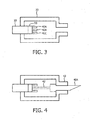
- a tool holder 20 attached to a OSS-enabled thether 10 may include one or more deployable tools.
- one or more tools 40A, 40B, 40C may be disposed on an actuation device 50 within the holder body 20.
- the actuation device may comprise one or more actuators 42, such as springs, solenoids, or the like to manipulate a selected tool 40A into coupled alignment with the fiber optic fiber 10 through a holding means 32, such as a tapered collet or the like, as shown in Fig. 4
- the actuation device 50 may deploy a selected tool 40A in response to a manual user input, a user input signal, a signal from an imaging system, or a signal from a sensor comprising another tool affixed to the holder body 20.
- a user provides an input to deploy a selected tool 40A, such as when the user determines that the holder body has been successfully navigated to an intervention target.
- the user input may be transmitted through the fiber optic fiber or through a wired or wireless signal, or through any other suitable transmission means.
- the manual user input may comprise, for example, pushing or pulling a release mechanism or a wire attached to a release mechanism holding the selected tool in an undeployed position in the holder body.
- the actuation device 50 includes or is operably connected with a logic device that determines when to deploy the selected tool 40A and triggers the actuation.
- the logic device may be internal to the holder body 20 or may be a workstation communicating with the actuation device, through the fiber optic fiber, wireless transmission, or any other suitable communication means.
- the logic device may determine when to deploy a selected tool 40A based on readings from a sensor that is one of the tools held by the holder body 20, or based on calculations from an imaging system, such as determination from the shape sensing that the holder body 20 is at a target location.
- the logic device may be one or more processors, such as microprocessors, programmable logic devices, such as EPROMS/EEPROMs, or any other suitable device.
- the actuation device may be triggered by a wired or wireless signal form the logic unit, time activation, magnetic activation, light activation, or any combination thereof.
- the tools 40A, 40B, etc. have an identification that can be read by the holder body 20 to identify a selected tool.
- the identification may be an etched or painted marking, an RFID chip, a magnetic identification, or any other identification suitable for reading with optical, radio frequency, magnetic or any other sensor that can be located in the holder body 20.
- the identification may be combined with a data library stored in a memory in the tool holder 20, accessible to the tool holder, or in a workstation in communication with the tool holder, or accessible to a workstation in communication with the tool holder.
- the library may comprise data for accurately representing the selected tool on an imaging system, for example. Also, the data may be used to optimize calibration, registration, or other usage of the tool in combination with the imaging and monitoring environment.
- a data storage device may be attached to or be integral with each tool.
- the data storage device may store data about the tool, such as tool identification and tool configuration for use in tip extrapolation and to accurately representing the tool on the OSS or other imaging display.
- the tool holder may be equipped with an appropriate sensor, such as an optical scanner, which may be located in the actuation device 50, for example, to read a data storage device at the back end of each tool.
- the tool holder 20 is equipped with a photodetector 24, as shown in Fig. 2 , for receiving communication signals through the fiber optic fiber 10.
- the photo detector 24 could also be a photo transceiver, both receiving and sending signals at the holder body 20, allowing communication to and from a OSS imaging workstation.
- the photo detector or photo transceiver is positioned adjacent the distal tip of the optic fiber to send and receive optical signals to and from the fiber.
- a logic device and sensor may be used to select, deploy, extend, retract, change, and operate various tools in the tool holder body 20.
- a user command may be sent through the optic fiber 10 to a photo detector 24 shown in Fig. 2 .
- the photodetector may then send the command signal to the logic device, which uses data storage devices on the tools to locate the identified tool and trigger the corresponding actuation device 50 to deploy the selected tool identified in the command.
- a sensor located near the back end of each tool can sense identification and other data about the tool and provide that data to the logic device. For example, temperature data may be received from a thermistor tool which can be provided to the logic device and used to determine when to stop an ablation tool, for example.
- the logic device may be operatively connected to a decision support database, so that the logic device selects or proposes specific tools based on application specific requirements and/or information in real time.
- a selected tool may be deployed or operated while the holder body is external to a patient, internal to a patient, or partially external to a patient.
- Fig. 5 is a flow diagram of a method for performing an intervention with a remotely triggered tool action.
- a logic device 830 shown in Fig. 8 , such as a microprocessor, receives a signal to perform a tool action (Step 510).
- the action may be to deploy, extend, retract, initiate, stop, or change a tool, or it may be any other action that may be performed by a tool.
- the signal may be a user initiated electronic signal transmitted through a wired connection or a wireless connection 850 or a user initiated optical signal transmitted over the fiber optic fiber 10 to a photodetector 24 operably connected to the logic device 830.
- the signal may be initiated by the OSS workstation, based on image analysis and communicated to the photodetector 24 or connection 850 by any suitable means.
- the signal may indicate or specify which tool is to perform an action.
- the logic device 830 identifies the specified tool (Step 520). That is, the logic device 830 uses one or more sensors 820 to read data 810 from the tools.
- the data may be a marking painted or etched onto the back of the tool, digital data stored in a data storage device attached to the back of the tool, an RFID chip attached to the back of the tool or any other form suitable for storing data on the tool.
- the sensor 820 is an optical scanner, wired or wireless connector, RFID rceiver, or other sensor suitable for retrieving the data 810 from the tool.
- the logic device triggers the appropriate tool action (Step 530).
- the logic device 830 is operably connected with an actuator 50 and the logic device 830 sends a signal that causes the actuator to actuate.
- the signal may cause a spring actuator to release a lock causing the spring to extend and push the tool into an extended position.
- the signal may trigger a solenoid to actuate and extend or retract the tool, or push a plunger of an injection tool, or open or close a gripping tool.
- the signal may turn on an electric motor for a drill tool or for a suction tool, turn on power for an ablation tool, change tools, initiate any other suitable tool action.
- Fig. 6 is a flow diagram of a method for performing an intervention with an automatically triggered action.
- the logic device 830 receives a triggering threshold (Step 610).
- the triggering threshold may be received, for example, from the OSS workstation, from another processing device, directly from a user input, or any other suitable source.
- the triggering threshold may be a sensor reading for a sensor tool in the tool holder 20, a period of time, or any other suitable parameter for a tool action.
- the logic device 830 receives parameter data (Step 620).
- the parameter data may be sensor readings, elapsed time from a timing circuit, or other suitable data.
- the logic device 830 compares the parameter data to the threshold (Step 625). If the data meets the threshold, then the logic device triggers a tool action (Step 630). If the data does not meet the threshold, then the logic device continues to compare the data to the threshold (Step 625).
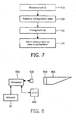
- Fig. 7 is a flow diagram of a method for performing an intervention with a communication between a smart tool holder and a OSS workstation .
- the logic device 830 retrieves a tool identification (Step 710).
- the tool identification may be retrieved from the tool using sensor 820.
- the logic device 830 also retrieves configuration data from a tool configuration database (Step 720). Using the configuration data, the logic device extrapolates the location of the tip of the tool relative to the distal tip of the shape sensing fiber (Step 730).
- the logic device sends the extrapolated tip data to the OSS work station (Step 740).
- the tip data may be sent to the workstation through the optic fiber as optical data via a photo transceiver 24 or through another connection 850 ( Fig. 8 ).
- the data may be sent from the logic device 830 to the OSS workstation or any other processing device through a wired or wireless connector.
- data may be sent from the OSS workstation or any other processing device to the logic device 830 in the tool holder body 20 through a photo transceiver 24 or other connection 850.
- the example can take the form of an entirely hardware embodiment or an embodiment containing both hardware and software elements.
- the invention is implemented in software, which includes but is not limited to firmware, resident software, microcode, etc.
- a computer program product may be provided. accessible from a computer-usable or computer-readable medium providing program code for use by or in connection with a computer or any instruction execution system or device.
- a computer-usable or computer readable medium may be any apparatus that can contain or store the program for use by or in connection with the instruction execution system, apparatus, or device.
- the foregoing method may be realized by a program product comprising a machine -readable medium having a machine-executable program of instructions, which when executed by a machine, such as a computer, performs the steps of the method.
- This program product may be stored on any of a variety of known machine-readable medium, including but not limited to compact discs, floppy discs, USB memory devices, and the like.
- the medium can be an electronic, magnetic, optical, electromagnetic, infrared, or semiconductor system (or apparatus or device).
- Examples of a computer-readable medium include a semiconductor or solid state memory, magnetic tape, a removable computer diskette, a random access memory (RAM), a read-only memory (ROM), a rigid magnetic disk an optical disk.
- Current examples of optical disks include compact disk-read only memory (CD-ROM), compact disk-read/write (CD-R/W) and DVD.
Claims (14)
- Einrichtung zur Aufnahme von Instrumenten während eines Interventionsvorgangs, wobei die Einrichtung umfasst:einen Aufnahmekörper (20) in fester Anlage an einem distalen Ende einer Tether (10) einer faseroptischen Shape-Sensing-Faser, dadurch gekennzeichnet, dass die Einrichtung weiterhin umfasst:mehrere in dem Aufnahmekörper aufgenommene Instrumente (22, 40A, 40B, 40C), wobei eines der mehreren Instrumente über den Aufnahmekörper eingesetzt und von diesem in gekoppelter Ausrichtung zu der faseroptischen Shape-Sensing-Faser gehalten wird.
- Einrichtung nach Anspruch 1, wobei es sich bei mindestens einem der Instrumente um einen Sensor (22) handelt, und wobei ein anderes Instrument in Reaktion auf Messergebnisse von dem Sensor verwendet wird.
- Einrichtung nach Anspruch 1, wobei das eine der mehreren Instrumente durch den Aufnahmekörper betrieben wird.
- Einrichtung nach Anspruch 3, die weiterhin eine Logikeinrichtung (830) umfasst, wobei die Logikeinrichtung das eine von mehreren Instrumenten aktiviert.
- Einrichtung nach Anspruch 4, wobei die Aktivierung das Initiieren eines Instrumenteneinsatzes umfasst.
- Einrichtung nach Anspruch 4, wobei die Aktivierung über ein optisches Signal durch die Tether (10) der faseroptischen Shape-Sensing-Faser ausgelöst wird.
- Einrichtung nach Anspruch 1, die weiterhin eine Prozessoreinrichtung und einen Sensor umfasst, wobei die mehreren Instrumente eine Identifikation umfassen, der Aufnahmekörper (20) ein eines der mehreren Instrumente haltendes Spannfutter (30) umfasst und der Sensor (22) die Identifikation auf einem der in dem Spannfutter gehaltenen Instrumente abtastet und der Prozessoreinrichtung diese Identifikation zur Identifizierung des einen der in dem Spannfutter gehaltenen mehreren Instrumente übermittelt.
- Einrichtung nach Anspruch 1, die weiterhin eine Prozessoreinrichtung (830) und einen Sensor (820) umfasst, wobei die mehreren Instrumente eine Identifikation umfassen, der Sensor die Identifikation abtastet und die Prozessoreinrichtung die Identifikation verwendet, um eines der Instrumente auszuwählen.
- Einrichtung nach Anspruch 1, die weiterhin einen Phototransceiver (24) in Angrenzung an ein distales Ende der Tether (10) der optischen Faser umfasst, um Daten (810) über die Tether der optischen Faser zu senden und zu empfangen.
- System zur Durchführung einer medizinischen Intervention, wobei das System umfasst:mindestens einen Prozessor (830);mindestens einen Speicher, der mit dem mindestens einen Prozessor betriebsbereit verbunden ist; sowiemindestens eine, mehrere Instrumente aufnehmende Einrichtung nach Anspruch 1, wobei der Prozessor einen Einsatz von mindestens einem der mehreren Instrumente initiiert.
- System nach Anspruch 10, wobei der Instrumentenhalter (20) ein Spannfutter (30) umfasst und der Instrumentenhalter in Reaktion auf ein Signal von dem Prozessor eines der mehreren Instrumente über das Spannfutter anwendet.
- System nach Anspruch 10, wobei das mindestens eine der mehreren Instrumente durch den initiierten Einsatz mit Energie versorgt wird.
- System nach Anspruch 10, wobei der Prozessor eines des mindestens einen der mehreren Instrumente auswählt.
- System nach Anspruch 10, wobei es sich bei dem Einsatz um die Übertragung von Daten von dem mindestens einen der mehreren Instrumente handelt.
Applications Claiming Priority (2)
| Application Number | Priority Date | Filing Date | Title |
|---|---|---|---|
| US201161551499P | 2011-10-26 | 2011-10-26 | |
| PCT/IB2012/055646 WO2013061212A1 (en) | 2011-10-26 | 2012-10-17 | Smart tool holder for an optical shape-sensing fiber |
Publications (2)
| Publication Number | Publication Date |
|---|---|
| EP2744439A1 EP2744439A1 (de) | 2014-06-25 |
| EP2744439B1 true EP2744439B1 (de) | 2015-06-17 |
Family
ID=47172846
Family Applications (1)
| Application Number | Title | Priority Date | Filing Date |
|---|---|---|---|
| EP12784346.4A Not-in-force EP2744439B1 (de) | 2011-10-26 | 2012-10-17 | Intelligenter werkzeughalter für eine optische formmessfaser |
Country Status (7)
| Country | Link |
|---|---|
| US (1) | US9405085B2 (de) |
| EP (1) | EP2744439B1 (de) |
| JP (1) | JP6155273B2 (de) |
| CN (1) | CN103957833B (de) |
| IN (1) | IN2014CN03100A (de) |
| MX (1) | MX2014004783A (de) |
| WO (1) | WO2013061212A1 (de) |
Families Citing this family (10)
| Publication number | Priority date | Publication date | Assignee | Title |
|---|---|---|---|---|
| JP6567532B2 (ja) * | 2013-09-12 | 2019-08-28 | インテュイティブ サージカル オペレーションズ, インコーポレイテッド | 局所的に移動可能な標的についての形状センサシステム |
| EP3052978B1 (de) * | 2013-09-30 | 2018-11-28 | Koninklijke Philips N.V. | Startarmatur für optische formmessung |
| US11432880B2 (en) | 2013-09-30 | 2022-09-06 | Koninklijke Philips N.V. | Docking device for optical shape sensing launch fixtures |
| WO2016038499A2 (en) * | 2014-09-08 | 2016-03-17 | Koninklijke Philips N.V. | Shape sensing for orthopedic navigation |
| US10722320B2 (en) * | 2015-03-31 | 2020-07-28 | Medtronic Navigation, Inc. | Thermo-electric generator |
| CN104777229B (zh) * | 2015-04-04 | 2018-01-05 | 上海和伍精密仪器股份有限公司 | 基于螺钉凸台的超声检测夹具类型智能识别方法及装置 |
| CN104792867A (zh) * | 2015-04-04 | 2015-07-22 | 上海和伍新材料科技有限公司 | 基于凸台的超声检测夹具类型的识别方法及装置 |
| EP3346899B1 (de) * | 2015-09-09 | 2022-11-09 | Auris Health, Inc. | Instrumentenmanipulator für ein chirurgisches robotersystem |
| JP2019526369A (ja) * | 2016-09-14 | 2019-09-19 | コーニンクレッカ フィリップス エヌ ヴェKoninklijke Philips N.V. | 光ファイバ付きの細長いデバイス |
| EP4151174A1 (de) * | 2021-09-15 | 2023-03-22 | Caranx Medical SAS | Vorrichtung zum einsetzen und austauschen eines chirurgischen instruments |
Family Cites Families (16)
| Publication number | Priority date | Publication date | Assignee | Title |
|---|---|---|---|---|
| US6860878B2 (en) * | 1998-02-24 | 2005-03-01 | Endovia Medical Inc. | Interchangeable instrument |
| US7742802B2 (en) * | 2004-03-11 | 2010-06-22 | Howmedica Osteonics Corp. | System for determining a position of a point on an object |
| US7772541B2 (en) * | 2004-07-16 | 2010-08-10 | Luna Innnovations Incorporated | Fiber optic position and/or shape sensing based on rayleigh scatter |
| CN2824861Y (zh) * | 2005-10-28 | 2006-10-11 | 北京光电技术研究所 | 侧出光激光光纤结构 |
| US9962066B2 (en) | 2005-12-30 | 2018-05-08 | Intuitive Surgical Operations, Inc. | Methods and apparatus to shape flexible entry guides for minimally invasive surgery |
| US7930065B2 (en) * | 2005-12-30 | 2011-04-19 | Intuitive Surgical Operations, Inc. | Robotic surgery system including position sensors using fiber bragg gratings |
| US8989528B2 (en) | 2006-02-22 | 2015-03-24 | Hansen Medical, Inc. | Optical fiber grating sensors and methods of manufacture |
| JP2009285204A (ja) * | 2008-05-29 | 2009-12-10 | Hoya Corp | 内視鏡用処置具 |
| US7720322B2 (en) * | 2008-06-30 | 2010-05-18 | Intuitive Surgical, Inc. | Fiber optic shape sensor |
| US8290571B2 (en) * | 2008-08-01 | 2012-10-16 | Koninklijke Philips Electronics N.V. | Auxiliary cavity localization |
| EP2165671B1 (de) | 2008-09-19 | 2011-06-01 | BrainLAB AG | Chirurgisches Pointerinstrument mit Spitzensensor |
| US9259274B2 (en) | 2008-09-30 | 2016-02-16 | Intuitive Surgical Operations, Inc. | Passive preload and capstan drive for surgical instruments |
| US8337397B2 (en) * | 2009-03-26 | 2012-12-25 | Intuitive Surgical Operations, Inc. | Method and system for providing visual guidance to an operator for steering a tip of an endoscopic device toward one or more landmarks in a patient |
| US10004387B2 (en) * | 2009-03-26 | 2018-06-26 | Intuitive Surgical Operations, Inc. | Method and system for assisting an operator in endoscopic navigation |
| US9285246B2 (en) * | 2010-02-12 | 2016-03-15 | Intuitive Surgical Operations, Inc. | Method and system for absolute three-dimensional measurements using a twist-insensitive shape sensor |
| CN103153223B (zh) * | 2010-10-08 | 2016-09-14 | 皇家飞利浦电子股份有限公司 | 用于动态仪器追踪的具有集成传感器的柔性线缆 |
-
2012
- 2012-10-17 US US14/353,830 patent/US9405085B2/en active Active
- 2012-10-17 IN IN3100CHN2014 patent/IN2014CN03100A/en unknown
- 2012-10-17 CN CN201280052571.9A patent/CN103957833B/zh not_active Expired - Fee Related
- 2012-10-17 JP JP2014537765A patent/JP6155273B2/ja not_active Expired - Fee Related
- 2012-10-17 EP EP12784346.4A patent/EP2744439B1/de not_active Not-in-force
- 2012-10-17 MX MX2014004783A patent/MX2014004783A/es unknown
- 2012-10-17 WO PCT/IB2012/055646 patent/WO2013061212A1/en active Application Filing
Also Published As
| Publication number | Publication date |
|---|---|
| IN2014CN03100A (de) | 2015-07-03 |
| JP6155273B2 (ja) | 2017-06-28 |
| WO2013061212A1 (en) | 2013-05-02 |
| CN103957833B (zh) | 2016-10-12 |
| MX2014004783A (es) | 2014-05-14 |
| JP2015504324A (ja) | 2015-02-12 |
| US9405085B2 (en) | 2016-08-02 |
| EP2744439A1 (de) | 2014-06-25 |
| US20140308016A1 (en) | 2014-10-16 |
| CN103957833A (zh) | 2014-07-30 |
Similar Documents
| Publication | Publication Date | Title |
|---|---|---|
| EP2744439B1 (de) | Intelligenter werkzeughalter für eine optische formmessfaser | |
| US20220087568A1 (en) | Systems and methods for medical procedure confirmation | |
| EP3621545B1 (de) | Robotisches wirbelsäulenchirurgiesystem | |
| CN106983557B (zh) | 用于执行外科手术的系统和活检工具 | |
| US9914211B2 (en) | Hand-guided automated positioning device controller | |
| CN112770691A (zh) | 用于机器人手术的带反馈的基准标记器 | |
| US20090247861A1 (en) | Calibration method for axially determinate medical instruments | |
| JP6573608B2 (ja) | 医療器具を位置検出システムに接続するためのデバイスおよび方法 | |
| EP2594221B1 (de) | In-situ-Näherungserkennungsvorrichtung | |
| EP3518797B1 (de) | Zugriffsvorrichtungen und zugehörige produktionsverfahren | |
| KR20210041563A (ko) | 기구 연결을 위한 시스템 및 방법 | |
| WO2015144246A1 (en) | Instrument for creating an artificial landmark on a surface of a bone and medical navigation system | |
| WO2020097481A1 (en) | Robotic spine surgery system and methods | |
| US20230355234A1 (en) | Surgical forceps and stapler |
Legal Events
| Date | Code | Title | Description |
|---|---|---|---|
| PUAI | Public reference made under article 153(3) epc to a published international application that has entered the european phase |
Free format text: ORIGINAL CODE: 0009012 |
|
| 17P | Request for examination filed |
Effective date: 20140320 |
|
| AK | Designated contracting states |
Kind code of ref document: A1 Designated state(s): AL AT BE BG CH CY CZ DE DK EE ES FI FR GB GR HR HU IE IS IT LI LT LU LV MC MK MT NL NO PL PT RO RS SE SI SK SM TR |
|
| REG | Reference to a national code |
Ref country code: DE Ref legal event code: R079 Ref document number: 602012008127 Country of ref document: DE Free format text: PREVIOUS MAIN CLASS: A61B0019000000 Ipc: A61B0010040000 |
|
| RIC1 | Information provided on ipc code assigned before grant |
Ipc: A61B 10/04 20060101AFI20141125BHEP |
|
| GRAP | Despatch of communication of intention to grant a patent |
Free format text: ORIGINAL CODE: EPIDOSNIGR1 |
|
| INTG | Intention to grant announced |
Effective date: 20150107 |
|
| GRAS | Grant fee paid |
Free format text: ORIGINAL CODE: EPIDOSNIGR3 |
|
| GRAA | (expected) grant |
Free format text: ORIGINAL CODE: 0009210 |
|
| AK | Designated contracting states |
Kind code of ref document: B1 Designated state(s): AL AT BE BG CH CY CZ DE DK EE ES FI FR GB GR HR HU IE IS IT LI LT LU LV MC MK MT NL NO PL PT RO RS SE SI SK SM TR |
|
| REG | Reference to a national code |
Ref country code: GB Ref legal event code: FG4D |
|
| REG | Reference to a national code |
Ref country code: CH Ref legal event code: EP |
|
| REG | Reference to a national code |
Ref country code: AT Ref legal event code: REF Ref document number: 731440 Country of ref document: AT Kind code of ref document: T Effective date: 20150715 |
|
| REG | Reference to a national code |
Ref country code: IE Ref legal event code: FG4D |
|
| REG | Reference to a national code |
Ref country code: DE Ref legal event code: R096 Ref document number: 602012008127 Country of ref document: DE |
|
| PG25 | Lapsed in a contracting state [announced via postgrant information from national office to epo] |
Ref country code: FI Free format text: LAPSE BECAUSE OF FAILURE TO SUBMIT A TRANSLATION OF THE DESCRIPTION OR TO PAY THE FEE WITHIN THE PRESCRIBED TIME-LIMIT Effective date: 20150617 Ref country code: HR Free format text: LAPSE BECAUSE OF FAILURE TO SUBMIT A TRANSLATION OF THE DESCRIPTION OR TO PAY THE FEE WITHIN THE PRESCRIBED TIME-LIMIT Effective date: 20150617 Ref country code: NO Free format text: LAPSE BECAUSE OF FAILURE TO SUBMIT A TRANSLATION OF THE DESCRIPTION OR TO PAY THE FEE WITHIN THE PRESCRIBED TIME-LIMIT Effective date: 20150917 Ref country code: LT Free format text: LAPSE BECAUSE OF FAILURE TO SUBMIT A TRANSLATION OF THE DESCRIPTION OR TO PAY THE FEE WITHIN THE PRESCRIBED TIME-LIMIT Effective date: 20150617 |
|
| REG | Reference to a national code |
Ref country code: FR Ref legal event code: PLFP Year of fee payment: 4 |
|
| REG | Reference to a national code |
Ref country code: AT Ref legal event code: MK05 Ref document number: 731440 Country of ref document: AT Kind code of ref document: T Effective date: 20150617 |
|
| REG | Reference to a national code |
Ref country code: LT Ref legal event code: MG4D Ref country code: NL Ref legal event code: MP Effective date: 20150617 |
|
| PG25 | Lapsed in a contracting state [announced via postgrant information from national office to epo] |
Ref country code: RS Free format text: LAPSE BECAUSE OF FAILURE TO SUBMIT A TRANSLATION OF THE DESCRIPTION OR TO PAY THE FEE WITHIN THE PRESCRIBED TIME-LIMIT Effective date: 20150617 Ref country code: BG Free format text: LAPSE BECAUSE OF FAILURE TO SUBMIT A TRANSLATION OF THE DESCRIPTION OR TO PAY THE FEE WITHIN THE PRESCRIBED TIME-LIMIT Effective date: 20150917 Ref country code: GR Free format text: LAPSE BECAUSE OF FAILURE TO SUBMIT A TRANSLATION OF THE DESCRIPTION OR TO PAY THE FEE WITHIN THE PRESCRIBED TIME-LIMIT Effective date: 20150918 Ref country code: LV Free format text: LAPSE BECAUSE OF FAILURE TO SUBMIT A TRANSLATION OF THE DESCRIPTION OR TO PAY THE FEE WITHIN THE PRESCRIBED TIME-LIMIT Effective date: 20150617 |
|
| PG25 | Lapsed in a contracting state [announced via postgrant information from national office to epo] |
Ref country code: EE Free format text: LAPSE BECAUSE OF FAILURE TO SUBMIT A TRANSLATION OF THE DESCRIPTION OR TO PAY THE FEE WITHIN THE PRESCRIBED TIME-LIMIT Effective date: 20150617 |
|
| PG25 | Lapsed in a contracting state [announced via postgrant information from national office to epo] |
Ref country code: ES Free format text: LAPSE BECAUSE OF FAILURE TO SUBMIT A TRANSLATION OF THE DESCRIPTION OR TO PAY THE FEE WITHIN THE PRESCRIBED TIME-LIMIT Effective date: 20150617 Ref country code: AT Free format text: LAPSE BECAUSE OF FAILURE TO SUBMIT A TRANSLATION OF THE DESCRIPTION OR TO PAY THE FEE WITHIN THE PRESCRIBED TIME-LIMIT Effective date: 20150617 Ref country code: CZ Free format text: LAPSE BECAUSE OF FAILURE TO SUBMIT A TRANSLATION OF THE DESCRIPTION OR TO PAY THE FEE WITHIN THE PRESCRIBED TIME-LIMIT Effective date: 20150617 Ref country code: RO Free format text: LAPSE BECAUSE OF NON-PAYMENT OF DUE FEES Effective date: 20150617 Ref country code: PL Free format text: LAPSE BECAUSE OF FAILURE TO SUBMIT A TRANSLATION OF THE DESCRIPTION OR TO PAY THE FEE WITHIN THE PRESCRIBED TIME-LIMIT Effective date: 20150617 Ref country code: IS Free format text: LAPSE BECAUSE OF FAILURE TO SUBMIT A TRANSLATION OF THE DESCRIPTION OR TO PAY THE FEE WITHIN THE PRESCRIBED TIME-LIMIT Effective date: 20151017 Ref country code: PT Free format text: LAPSE BECAUSE OF FAILURE TO SUBMIT A TRANSLATION OF THE DESCRIPTION OR TO PAY THE FEE WITHIN THE PRESCRIBED TIME-LIMIT Effective date: 20151019 Ref country code: SK Free format text: LAPSE BECAUSE OF FAILURE TO SUBMIT A TRANSLATION OF THE DESCRIPTION OR TO PAY THE FEE WITHIN THE PRESCRIBED TIME-LIMIT Effective date: 20150617 |
|
| REG | Reference to a national code |
Ref country code: DE Ref legal event code: R097 Ref document number: 602012008127 Country of ref document: DE |
|
| PLBE | No opposition filed within time limit |
Free format text: ORIGINAL CODE: 0009261 |
|
| STAA | Information on the status of an ep patent application or granted ep patent |
Free format text: STATUS: NO OPPOSITION FILED WITHIN TIME LIMIT |
|
| PG25 | Lapsed in a contracting state [announced via postgrant information from national office to epo] |
Ref country code: IT Free format text: LAPSE BECAUSE OF FAILURE TO SUBMIT A TRANSLATION OF THE DESCRIPTION OR TO PAY THE FEE WITHIN THE PRESCRIBED TIME-LIMIT Effective date: 20150617 Ref country code: DK Free format text: LAPSE BECAUSE OF FAILURE TO SUBMIT A TRANSLATION OF THE DESCRIPTION OR TO PAY THE FEE WITHIN THE PRESCRIBED TIME-LIMIT Effective date: 20150617 |
|
| 26N | No opposition filed |
Effective date: 20160318 |
|
| PG25 | Lapsed in a contracting state [announced via postgrant information from national office to epo] |
Ref country code: LU Free format text: LAPSE BECAUSE OF FAILURE TO SUBMIT A TRANSLATION OF THE DESCRIPTION OR TO PAY THE FEE WITHIN THE PRESCRIBED TIME-LIMIT Effective date: 20151017 |
|
| REG | Reference to a national code |
Ref country code: CH Ref legal event code: PL |
|
| PG25 | Lapsed in a contracting state [announced via postgrant information from national office to epo] |
Ref country code: MC Free format text: LAPSE BECAUSE OF FAILURE TO SUBMIT A TRANSLATION OF THE DESCRIPTION OR TO PAY THE FEE WITHIN THE PRESCRIBED TIME-LIMIT Effective date: 20150617 |
|
| REG | Reference to a national code |
Ref country code: IE Ref legal event code: MM4A |
|
| PG25 | Lapsed in a contracting state [announced via postgrant information from national office to epo] |
Ref country code: LI Free format text: LAPSE BECAUSE OF NON-PAYMENT OF DUE FEES Effective date: 20151031 Ref country code: CH Free format text: LAPSE BECAUSE OF NON-PAYMENT OF DUE FEES Effective date: 20151031 |
|
| PG25 | Lapsed in a contracting state [announced via postgrant information from national office to epo] |
Ref country code: SI Free format text: LAPSE BECAUSE OF FAILURE TO SUBMIT A TRANSLATION OF THE DESCRIPTION OR TO PAY THE FEE WITHIN THE PRESCRIBED TIME-LIMIT Effective date: 20150617 |
|
| REG | Reference to a national code |
Ref country code: FR Ref legal event code: PLFP Year of fee payment: 5 |
|
| PG25 | Lapsed in a contracting state [announced via postgrant information from national office to epo] |
Ref country code: IE Free format text: LAPSE BECAUSE OF NON-PAYMENT OF DUE FEES Effective date: 20151017 |
|
| PG25 | Lapsed in a contracting state [announced via postgrant information from national office to epo] |
Ref country code: BE Free format text: LAPSE BECAUSE OF FAILURE TO SUBMIT A TRANSLATION OF THE DESCRIPTION OR TO PAY THE FEE WITHIN THE PRESCRIBED TIME-LIMIT Effective date: 20150617 |
|
| PG25 | Lapsed in a contracting state [announced via postgrant information from national office to epo] |
Ref country code: SM Free format text: LAPSE BECAUSE OF FAILURE TO SUBMIT A TRANSLATION OF THE DESCRIPTION OR TO PAY THE FEE WITHIN THE PRESCRIBED TIME-LIMIT Effective date: 20150617 Ref country code: HU Free format text: LAPSE BECAUSE OF FAILURE TO SUBMIT A TRANSLATION OF THE DESCRIPTION OR TO PAY THE FEE WITHIN THE PRESCRIBED TIME-LIMIT; INVALID AB INITIO Effective date: 20121017 |
|
| PG25 | Lapsed in a contracting state [announced via postgrant information from national office to epo] |
Ref country code: CY Free format text: LAPSE BECAUSE OF FAILURE TO SUBMIT A TRANSLATION OF THE DESCRIPTION OR TO PAY THE FEE WITHIN THE PRESCRIBED TIME-LIMIT Effective date: 20150617 Ref country code: NL Free format text: LAPSE BECAUSE OF FAILURE TO SUBMIT A TRANSLATION OF THE DESCRIPTION OR TO PAY THE FEE WITHIN THE PRESCRIBED TIME-LIMIT Effective date: 20150617 Ref country code: SE Free format text: LAPSE BECAUSE OF FAILURE TO SUBMIT A TRANSLATION OF THE DESCRIPTION OR TO PAY THE FEE WITHIN THE PRESCRIBED TIME-LIMIT Effective date: 20150617 |
|
| PG25 | Lapsed in a contracting state [announced via postgrant information from national office to epo] |
Ref country code: MT Free format text: LAPSE BECAUSE OF FAILURE TO SUBMIT A TRANSLATION OF THE DESCRIPTION OR TO PAY THE FEE WITHIN THE PRESCRIBED TIME-LIMIT Effective date: 20150617 |
|
| REG | Reference to a national code |
Ref country code: FR Ref legal event code: PLFP Year of fee payment: 6 |
|
| PG25 | Lapsed in a contracting state [announced via postgrant information from national office to epo] |
Ref country code: MK Free format text: LAPSE BECAUSE OF FAILURE TO SUBMIT A TRANSLATION OF THE DESCRIPTION OR TO PAY THE FEE WITHIN THE PRESCRIBED TIME-LIMIT Effective date: 20150617 |
|
| REG | Reference to a national code |
Ref country code: FR Ref legal event code: PLFP Year of fee payment: 7 |
|
| PG25 | Lapsed in a contracting state [announced via postgrant information from national office to epo] |
Ref country code: TR Free format text: LAPSE BECAUSE OF FAILURE TO SUBMIT A TRANSLATION OF THE DESCRIPTION OR TO PAY THE FEE WITHIN THE PRESCRIBED TIME-LIMIT Effective date: 20150617 Ref country code: AL Free format text: LAPSE BECAUSE OF FAILURE TO SUBMIT A TRANSLATION OF THE DESCRIPTION OR TO PAY THE FEE WITHIN THE PRESCRIBED TIME-LIMIT Effective date: 20150617 |
|
| PGFP | Annual fee paid to national office [announced via postgrant information from national office to epo] |
Ref country code: FR Payment date: 20201027 Year of fee payment: 9 Ref country code: GB Payment date: 20201027 Year of fee payment: 9 Ref country code: DE Payment date: 20201030 Year of fee payment: 9 |
|
| REG | Reference to a national code |
Ref country code: DE Ref legal event code: R119 Ref document number: 602012008127 Country of ref document: DE |
|
| GBPC | Gb: european patent ceased through non-payment of renewal fee |
Effective date: 20211017 |
|
| PG25 | Lapsed in a contracting state [announced via postgrant information from national office to epo] |
Ref country code: GB Free format text: LAPSE BECAUSE OF NON-PAYMENT OF DUE FEES Effective date: 20211017 Ref country code: DE Free format text: LAPSE BECAUSE OF NON-PAYMENT OF DUE FEES Effective date: 20220503 |
|
| PG25 | Lapsed in a contracting state [announced via postgrant information from national office to epo] |
Ref country code: FR Free format text: LAPSE BECAUSE OF NON-PAYMENT OF DUE FEES Effective date: 20211031 |