EP2744383B1 - Apparatus for attaching a filter bag to a vacuum sweeper, such a filter bag and a method of attachment - Google Patents
Apparatus for attaching a filter bag to a vacuum sweeper, such a filter bag and a method of attachment Download PDFInfo
- Publication number
- EP2744383B1 EP2744383B1 EP11796904.8A EP11796904A EP2744383B1 EP 2744383 B1 EP2744383 B1 EP 2744383B1 EP 11796904 A EP11796904 A EP 11796904A EP 2744383 B1 EP2744383 B1 EP 2744383B1
- Authority
- EP
- European Patent Office
- Prior art keywords
- filter bag
- top plate
- sled
- key
- lock
- Prior art date
- Legal status (The legal status is an assumption and is not a legal conclusion. Google has not performed a legal analysis and makes no representation as to the accuracy of the status listed.)
- Active
Links
Images


Classifications
-
- A—HUMAN NECESSITIES
- A47—FURNITURE; DOMESTIC ARTICLES OR APPLIANCES; COFFEE MILLS; SPICE MILLS; SUCTION CLEANERS IN GENERAL
- A47L—DOMESTIC WASHING OR CLEANING; SUCTION CLEANERS IN GENERAL
- A47L9/00—Details or accessories of suction cleaners, e.g. mechanical means for controlling the suction or for effecting pulsating action; Storing devices specially adapted to suction cleaners or parts thereof; Carrying-vehicles specially adapted for suction cleaners
- A47L9/10—Filters; Dust separators; Dust removal; Automatic exchange of filters
- A47L9/14—Bags or the like; Rigid filtering receptacles; Attachment of, or closures for, bags or receptacles
- A47L9/1427—Means for mounting or attaching bags or filtering receptacles in suction cleaners; Adapters
- A47L9/1436—Connecting plates, e.g. collars, end closures
-
- A—HUMAN NECESSITIES
- A47—FURNITURE; DOMESTIC ARTICLES OR APPLIANCES; COFFEE MILLS; SPICE MILLS; SUCTION CLEANERS IN GENERAL
- A47L—DOMESTIC WASHING OR CLEANING; SUCTION CLEANERS IN GENERAL
- A47L9/00—Details or accessories of suction cleaners, e.g. mechanical means for controlling the suction or for effecting pulsating action; Storing devices specially adapted to suction cleaners or parts thereof; Carrying-vehicles specially adapted for suction cleaners
- A47L9/10—Filters; Dust separators; Dust removal; Automatic exchange of filters
- A47L9/14—Bags or the like; Rigid filtering receptacles; Attachment of, or closures for, bags or receptacles
- A47L9/1427—Means for mounting or attaching bags or filtering receptacles in suction cleaners; Adapters
- A47L9/1472—Means for mounting or attaching bags or filtering receptacles in suction cleaners; Adapters combined with security means, e.g. for preventing use, e.g. in case of absence of the bag
-
- Y—GENERAL TAGGING OF NEW TECHNOLOGICAL DEVELOPMENTS; GENERAL TAGGING OF CROSS-SECTIONAL TECHNOLOGIES SPANNING OVER SEVERAL SECTIONS OF THE IPC; TECHNICAL SUBJECTS COVERED BY FORMER USPC CROSS-REFERENCE ART COLLECTIONS [XRACs] AND DIGESTS
- Y10—TECHNICAL SUBJECTS COVERED BY FORMER USPC
- Y10T—TECHNICAL SUBJECTS COVERED BY FORMER US CLASSIFICATION
- Y10T29/00—Metal working
- Y10T29/49—Method of mechanical manufacture
- Y10T29/49826—Assembling or joining
-
- Y—GENERAL TAGGING OF NEW TECHNOLOGICAL DEVELOPMENTS; GENERAL TAGGING OF CROSS-SECTIONAL TECHNOLOGIES SPANNING OVER SEVERAL SECTIONS OF THE IPC; TECHNICAL SUBJECTS COVERED BY FORMER USPC CROSS-REFERENCE ART COLLECTIONS [XRACs] AND DIGESTS
- Y10—TECHNICAL SUBJECTS COVERED BY FORMER USPC
- Y10T—TECHNICAL SUBJECTS COVERED BY FORMER US CLASSIFICATION
- Y10T29/00—Metal working
- Y10T29/53—Means to assemble or disassemble
Definitions
- This invention relates generally to vacuum sweepers, and more specifically to an apparatus for attaching a filter bag to a vacuum sweeper including a filter bag and a method of installation.
- vacuum suction causes the dust and debris to become airborne.
- the air containing the dust and debris is directed to a compartment and filtered to remove the dust and debris.
- a filter bag is positioned within the compartment and utilized for separating the dust and debris from the air.
- the filter bag not only separates the contaminants from the air but also collects the dust and debris.
- the filter bag can be disposed of along with the dust and debris. A replacement filter bag can then be used for continued vacuum sweeper operations.
- Filter bags should be constructed according to the vacuum sweeper manufacturer's specifications to ensure proper fit and performance.
- Document DE 34 03 121 A1 discloses a vacuum cleaner housing which can receive a stiffening plate of a filter bag.
- filter bags that do not meet the manufacturer's specifications can be problematic.
- filter bags that do not meet the manufacturer's specifications can reduce the performance of the vacuum sweeper and/or its safety characteristics.
- the present invention is directed to an improved vacuum sweeper filter bag, an apparatus for attaching a filter bag to a vacuum sweeper including said filter bag, and a method of installation.
- the present invention is a filter bag.
- the filter bag comprises a bag portion for collecting debris material and a top plate attached to the bag portion.
- the top plate includes a key formed thereon.
- the present invention is an apparatus for attaching a filter bag to a vacuum sweeper.
- the apparatus comprises a sled and a sweeper housing.
- the sled is configured to receive a portion of the filter bag having a key formed thereon.
- the sweeper housing is adjacent the sled and includes a cavity for receiving a portion of the filter bag and a lock that interconnects with the key.
- a method for installing a filter bag in a vacuum sweeper comprises providing a filter bag having a top plate.
- a key is formed on the top plate.
- the method also comprises providing a sled configured to receive the filter bag top plate and providing a lock adjacent the sled. Further, the method comprises positioning the filter bag top plate within the sled and interconnecting the key and the lock so that the filter bag is selectively attached to the vacuum sweeper.
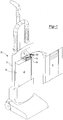
- the present invention is preferably practiced with an upright vacuum sweeper 10.
- An example of an upright vacuum sweeper 10 utilized when practicing the present invention is shown in Fig. 1 .
- a preferred brand of upright vacuum sweeper 10 utilized when practicing the present invention is an NSS Pacer brand vacuum sweeper. It should also be appreciated that although the present invention will be described in connection with upright vacuum sweeper 10 the present invention is not so limited and may be used with any upright vacuum sweeper or any sweeper.
- the vacuum sweepers which are suitable for practice with the present invention have a housing 12.
- the housing 12 protects a fan (not depicted) and a motor (not depicted).
- the motor drives the fan which then creates a pressure difference which in turn provides suction for the sweeper 10.
- the housing 12 may have a cavity 14. As depicted, an air outlet 16 may be located within the cavity 14. It should be noted that for the convenience of illustrating other aspects of the invention, a portion of the air outlet 16 has been removed from FIG. 1 .
- the housing 12 may also include a removable cover panel 18 for gaining access to and enclosing the cavity 14.
- the present invention is directed to a filter bag 20.
- the filter bag 20 When installed for operation, the filter bag 20 is preferably located within the vacuum sweeper cavity 14.
- the filter bag 20 is in fluid communication with the air outlet 16 so that the filter bag 20 can receive dust and debris material contained within the airstream from the vacuum sweeper 10.
- the filter bag 20 separates the dust and debris material from the air and also collects the dust and debris.
- the filter bag 20 comprises a bag portion 22 and a top plate 24.
- the bag portion 22 is utilized for collecting and storing the dust and debris material.
- the bag portion 22 may be of a generally tubular shape and includes an interior 26 and an exterior 28.
- the bag portion 22 may have sidewalls 30 and a pair of closed ends 32 which define the interior 26 and exterior 28.
- One of the closed ends 32 has an opening 34 formed therein for allowing air from the air outlet 16 into the interior 26 of the filter bag 20. When air is moved through or debris is collected within the interior 26 of the filter bag 20, the bag portion 22 may expand.
- the bag portion 22 can be made from any suitable filter media material. Suitable materials include porous materials, such as paper, and non-porous materials. The bag portion 22 may also be formed from several layers of material and may include an inner liner.
- the top plate 24 is attached to the bag portion 22 so that the opening 34 formed in the closed end 32 is in fluid communication within an opening 36 formed in the top plate 24.
- the top plate opening 36 and the bag portion opening 34 are preferably concentric but need not be to practice the present invention.
- the top plate opening 36 is attached to and surrounds the air outlet 16.
- the bag portion 22 is attached to the top plate 24 with an adhesive.
- the adhesive may be disposed on the closed end 32 and around the openings 34, 36 in the bag portion 22 and the top plate 24.
- a seal ring 35 may be positioned around the openings 34, 36 in the bag portion 22 and the top plate 24.
- the seal ring 35 has a first surface which is attached to the closed end 32 of the bag portion 22 and a second surface which is attached to a lower surface 38B of the top plate 24.
- the adhesive may be disposed on and around the seal ring 35 to attach the bag portion 22 to the top plate 24 and provide an effective seal there between.
- the top plate 24 has two generally parallel and planar surfaces 38A, 38B with the opening 36 formed therein extending between each surface 38A, 38B.
- the lower surface 38B is positioned between the upper surface 38A and the bag portion 22.
- the top plate opening 36 is formed in a center portion 44 of the top plate 24, but may be offset as well.
- Each 38A, 38B has at least two edge portions 40, 42 and the center portion 44.
- the top plate 24 has at least four edge portions 40, 42, 46, 48.
- the edge portions 40, 42, 46, 48 extend radially outward from the center portion 44 and from the upper surface 38A to the lower surface 38B. It is preferred that the edge portions 40, 42, 46, 48 and the center portion 44 are configured to provide a unitary top plate 24.
- the top plate 24 includes a key 50 formed thereon.
- the key 50 is formed in the first edge portion 40 of the top plate 24 and more preferably as a part of an edge 52 of the top plate 24.
- the second edge portion 42 is located opposite the first edge portion 40.
- a spring receiving portion 54 is formed in the second edge portion 42. In an embodiment, the spring receiving portion 54 has a concave shape.
- the top plate 24 may have a generally rectangular shape.
- the third edge portion 46 has a first chamfered edge 53 and a second chamfered edge 55.
- the chamfered edges 53, 55 combine to reduce the area of the third edge portion 46 and make installing the filter bag 20 in a sled 80 easier.
- the top plate 24 and key 50 are unitary.
- the key 50 selectively interconnects with a lock 56 located on the vacuum sweeper 10. Since it is contemplated that the key 50 may be interconnected, disconnected, and then reconnected with the lock 56, it is preferable that the top plate 24 is formed of a durable material. Even more preferred is that the top plate 24 is formed from a material which provides a relative amount of rigidity. A cost effective, durable, and relatively rigid material capable of being utilized to form the top plate 24 is cardboard.
- the key 50 includes a blade 58 and a non-blade portion 60.
- the blade 58 is the portion of the key 50 that interconnects with the lock 56.
- the blade 58 is formed in a unitary manner with the non-blade portion 60. As shown, in an embodiment, the blade 58 is positioned on an end portion 62 and the non-blade portion 60 is positioned on an opposite end portion 64 of the key 50. In this embodiment, the blade 58 is a contiguous body.
- alternative orientations of the blade and non-blade portions 58, 60 may be utilized in practicing the present invention. For example, the non-blade portion 60 could be positioned between portions of the blade 58.
- the blade 58 comprises a plurality of teeth 66. Most preferably, the blade 58 has four teeth. However, it should be appreciated that the blade 58 may have many more than four teeth. Additionally, in certain embodiments, it is possible to practice the present invention when the blade 58 has a single tooth.
- each tooth 66 extend out beyond the non-blade portion 60.
- each tooth 66 has substantially the same size.
- each tooth 66 may have substantially the same shape.
- each tooth 66 can have a full or partial square, rectangle, triangle, pie, trapezoid, ellipse, semi-ellipse, semi-circular, or oval shape.
- each tooth 66 can be of a combination of these and/or other shapes.
- each tooth 66 may comprise a crest 70 and angled sidewalls 72.
- the teeth 66 need not be similarly shaped or sized to practice the present invention.
- a shaped segment 74 may be attached to each tooth 66.
- a shaped segment 74 may be positioned between each pair of teeth 66.
- the blade 58 may comprise a plurality of shaped segments 74.
- each shaped segment 74 is a valley 76 between pairs of teeth 66.
- each valley 76 includes a concave shape.
- the teeth 66 and valleys 76 can be arranged to provide a waveform shape, preferably sinusoidal.
- a repeating pattern across the key 50 may be provided.
- the shaped segments 74 may, but need not, be similarly shaped and/or sized to practice the present invention.
- the present invention is directed to an apparatus 78 for attaching the filter bag 20 to the vacuum sweeper 10.
- the apparatus 78 comprises the sled 80 and the lock 56.
- the apparatus 78 is practiced utilizing the filter bag 20 described above.
- other filter bags may be utilized with the apparatus 78.
- the sled 80 is configured to receive at least a portion 22, 24 of the filter bag 20.
- the filter bag 20 is preferably located within the vacuum sweeper cavity 14. Since the sled 80 is configured to receive a portion of the filter bag 20, the sled 80 is also preferably located within the cavity 14. Also, it is contemplated that filter bags will be removed from and received by the sled 80 many times. Therefore, it is preferred that the sled 80 is formed with a durable material such as a hard plastic.
- the sled 80 comprises an upper flange 82, a lower flange 84, and a sled body 86.
- the upper flange 82 and the lower flange 84 are positioned proximate each other and are attached to a wall 88.
- the wall 88 is perpendicular to the flanges 82, 84 and surrounds each flange 82, 84 on three sides.
- the upper flange 82 and the lower flange 84 are configured to receive the top plate 24 of the filter bag 20.
- the top plate 24 is received between the upper flange 82 and the lower flange 84.
- the lower flange 84 supports the top plate 24 and, thus, the filter bag 20.
- the upper flange 82 and lower flange 84 Prior to receiving the top plate 24, the upper flange 82 and lower flange 84 are separated by a space or slot 90.
- the height of the slot 90 is at least equal to or, preferably, slightly greater than the thickness of the top plate 24.
- Each flange 82, 84 includes a first leg 92, 96 and a second leg 94, 98.
- the upper flange first leg 92 is substantially a mirror image of the upper flange second leg 94.
- the lower flange first leg 96 and second leg 98 may be differently shaped.
- the lower flange first leg 96 has an edge portion 100 which is shaped like the blade 58 so that the lower flange first leg 96 can move vertically past an end 99 of the lock 56.
- the lower flange second leg 98 has a substantially planar shape.
- the upper flange first leg 92 may have an edge portion which is shaped like the lower flange first leg edge portion 100.
- Apertures 102, 104 are formed in both the upper flange 82 and the lower flange 84.
- the upper aperture 102 and lower aperture 104 are located between the first legs 92, 96 and the second legs 94, 98 of each flange 82, 84.
- the apertures 102,104 may have a generally U-shape and the aperture 104 in the lower flange 84 may be larger than the aperture 102 formed in the upper flange 82.
- the air outlet 16 may extend through the aperture 102 in the upper flange 82 so that the top plate opening 36 and the air outlet 16 can be in communication when the filter bag 20 is installed.
- the upper flange 82, the lower flange 84, and the wall 88 are attached to the sled body 86.
- the sled body 86 provides support to the flanges 82, 84 and the wall 88. In certain embodiments, the sled body 86 may also help to stabilize the movement of the sled 80 within the vacuum sweeper cavity 14.
- the sled body 86 may comprise a back plate 106 and an arm 108.
- the back plate 106 and the arm 108 are formed in a unitary manner and are in a perpendicular relationship.
- a portion of the arm 108 is attached to a side 110 of the back plate 106 nearest the lock 56. Another portion of the arm 108 is attached to the lower flange 84.
- the arm 108 provides support to the lower flange 84. Specifically, the arm 108 provides support to the first leg 96 of the lower flange 84.
- the arm 108 is tapered.
- the back plate 106 is also attached to the wall 88 and the lower flange 84 and provides support to both.
- a slit 112 may be formed in the back plate 106.
- the slit 112 is located so that it communicates with the slot 90 between the upper and lower flanges 82, 84.
- a safety stop (not depicted) is located adjacent the slit 112.
- one of the top plate chamfered edges 53, 55 may extend through the slit 112 and contact the safety stop.
- the second chamfered edge 55 is utilized for this purpose. Contact with one or both of the chamfered edges 53, 55 releases the safety stop so that the position of the sled 80 can be adjusted vertically.
- the sled 80 may further comprise a spring 114.
- the spring 114 is attached to an inner portion 116 of the wall 88 and extends horizontally into the slot 90.
- the spring 114 contacts the spring receiving portion 54 of the top plate 24 to apply a force to the top plate 24. As shown in FIG. 8 , the spring 114 contacts the spring receiving portion 54 at or near its center.
- the spring 114 can be of the leaf spring variety.
- the arch of the leaf spring is preferably slightly larger than the concave shape of the spring receiving portion 54.
- a coil spring could be utilized. Additional elements to ensure good contact between the top plate 24 and the spring 114 may be further included when practicing the present invention.
- a pivotally mounted guide (not depicted) may be utilized with a coil spring to ensure good contact between the spring receiving portion 54 and the spring 114.
- the position of the sled 80 is adjustable.
- the sled is adjustable in a vertical direction from a lowered-position to a raised-position and vice versa.
- the sled's flanges 82, 84 and slot 90 are positioned below the end 99 of the lock 56.
- the flanges 82, 84 and slot 90 are positioned across from the lock 56.
- the position of the sled 80 may be adjusted vertically with the use of a rod 118.
- the rod 118 is fixedly attached to the sled 80.
- the rod 118 is configured in an L-shape.
- the rod 118 may enter a lower portion 120 of the back plate 106 and extend vertically there through before turning 90° and extending through and beyond the arm 108.
- the rod 118 also extends beyond a portion 122 of the sweeper housing 12 positioned adjacent the sled 80 through an aperture 124 formed in the housing 12.
- the rod 118 can assume other shapes and configurations.
- the rod 118 or substantial portions thereof may be located adjacent the sled body 86.
- An end portion 126 of the rod 118 is attached to a lever 128.
- the lever 128 is connected to the sled 80 via the rod 118.
- the lever 128 may be attached directly to the sled 80.
- the lever 128 comprises an arm 130 and a body 132.
- the arm 130 is integrally formed with the body 132.
- the arm 130 extends outward from the body 132 and may include a knob 134.
- the body 132 has a substantially oval shape.
- a center portion 136 of the body 132 is attached to a pivot point 138 on the housing 12 for rotation thereabout.
- the lever 128 can be rotated 90° about the pivot point 138 from a raised-position to a lowered-position and vice versa. To move the lever 128 between these two positions, the lever 128 can be manually adjusted by application of physical force to the arm 130, preferably the knob 134.
- the force may be provided directly by a vacuum sweeper operator. However, it should be appreciated that the force to rotate the lever 128 could be provided by the operator via an electro-mechanical mechanism.
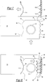
- Rotation of the lever 128 moves the rod 118 in a vertical direction. Since the rod 118 is attached to the sled 80, changing the position of the lever 128 also vertically adjusts the position of the sled 80. As shown in FIG. 5 by directional arrows A and B, when downward force is applied to the arm 130, the lever 128 is rotated into its lowered-position and the sled 80 moves vertically into its raised-position. However, as shown in FIG. 6 by directional arrows C and D, upon application of an opposite force to the lever 128, the lever 128 is rotated into its raised-position and the sled 80 moves vertically into its lowered-position.
- the lock 56 is attached to the vacuum sweeper 10.
- the lock 56 is formed in a unitary manner with the vacuum sweeper housing 12.
- the portion 122 of the sweeper housing 12 positioned adjacent the sled 80 includes the lock 56 formed thereon.
- this portion 122 of the sweeper housing 12 can be formed in a unitary manner with the main body of the sweeper housing 12.
- this portion 122 of the sweeper housing 12 can be a separate piece and attached to the main portion of the sweeper housing 12 with screws (not depicted) or another type of fastener through holes 133.
- the lock 56 is attached to a wall 140 on the sweeper housing 12.
- the wall 140 extends in a vertical direction.
- the vertical wall 140 may have a substantially planar portion which is positioned in a parallel spaced apart relationship with the arm 108.
- the first legs 92, 96 of the upper and lower flanges 82, 84 may contact the planar portion of the vertical wall 140.
- the lock 56 and the key 50 are configured to selectively interconnect.
- Selectively interconnect means that the lock 56 and the key 50 can be interconnected before operating the vacuum sweeper 10 and disconnected when removing, emptying, and/or replacing the filter bag 20.
- the lock 56 is formed to have a shape which allows the lock 56 and the key 50 to engage each other.
- the lock 56 comprises a plurality of teeth 142.
- the teeth 66, 142 of the key 50 and the lock 56 may be equal in number.
- the teeth 66, 142 need not be equal in number for the key 50 and the lock 56 to be engaged.
- the teeth 66, 142 are horizontally offset from each other.
- the lock 56 may comprise a single concave valley portion.
- the teeth 142 on the lock 56 may be substantially the same size and shape as each other and the teeth 66 of the key 50. However, variations between the shape and size of the teeth 66, 142 are acceptable for practicing the present invention. For example, in a preferable embodiment, the teeth 142 extend to the end 99 of the lock 56 in a substantially vertical direction so that their height is greater than that of the teeth 66 of the key 50.
- a first tooth 144 on the lock 56 has a vertical groove 146.
- a guide 148 is attached to the upper flange first leg 92 and the wall 88. The guide 148 is interlocked with the groove 146. The interlock between the groove 146 and the guide 148 provides a repeatable course for the sled 80 to follow so that it is located in the same raised- and lowered-position when the lever 128 is rotated. Also, this arrangement ensures that communication between the air outlet 16 and the top plate 24 opening 36 occurs without interference when a filter bag 20 is installed in the vacuum sweeper 10.
- a method for installing the filter bag 20 in the vacuum sweeper 10 is also provided.
- the method comprises providing the filter bag 20, the sled 80, and the lock 56.
- the filter bag 20 has the top plate 24 and the key 50 formed thereon
- the sled 80 is configured to receive the top plate 24, and the lock 56 is adjacent the sled 80.
- the position of the sled 80 can be adjusted from its lowered-position to its raised-position and vice versa. It is preferred that for installation of the filter bag 20, the sled 80 is initially in its lowered-position as depicted in FIG. 5 .
- the method may further comprise applying a force to the arm 130 so that the lever 128 is rotated into its raised-position and the sled 80 is adjusted to its lowered-position.
- the filter bag top plate 24 is moved in a horizontal direction and slid into the slot 90 between the upper flange 82 and the lower flange 84. As shown in FIG. 7 , upon entering the slot 90, a portion of the top plate 24 moves past the spring 114. Then, as shown in FIG. 8 , the spring 114 applies a force to the spring receiving portion 54 on the top plate 24. Upon application of the spring force, the top plate 24 is moved in a direction opposite the force until it contacts the vertical wall 140 located on the housing 12.
- the sled 80 can then be adjusted in a vertical direction from its lowered-position to its raised-position. As shown by directional arrows A and B, when a downward force is applied to the arm 130, the lever 128 is rotated into its lowered-position and the sled 80 moves vertically into its raised-position as shown in FIG. 6 .
- the key 50 and lock 56 interconnect.
- the key 50 and lock 56 When the key 50 and lock 56 are interconnected, communication between the top plate opening 36, the bag portion opening 34, and the air outlet 16 is established.
- the filter bag 20 is considered to be installed such that dust and debris material can be collected therein from a surface by the vacuum sweeper 10.
- the filter bag 20 can be removed from the vacuum sweeper 10 by reversal of the above-described method.
- the key 50 and lock 56 can be disconnected upon application of an upward force to the lever 128.
- Rotation of the lever 128 into its raised-position and vertical movement of the sled 80 into its lowered-position is shown by directional arrows C and D.
- the filter bag 20 is selectively attached to the vacuum sweeper 10.
Landscapes
- Engineering & Computer Science (AREA)
- Mechanical Engineering (AREA)
- Filters For Electric Vacuum Cleaners (AREA)
Applications Claiming Priority (2)
| Application Number | Priority Date | Filing Date | Title |
|---|---|---|---|
| US13/210,840 US8439997B2 (en) | 2011-08-16 | 2011-08-16 | Vacuum sweeper apparatus including a filter bag and a method of installation |
| PCT/US2011/063918 WO2013025234A1 (en) | 2011-08-16 | 2011-12-08 | Apparatus for attaching a filter bag to a vacuum sweeper, such a filter bag and a method of attachment |
Publications (2)
| Publication Number | Publication Date |
|---|---|
| EP2744383A1 EP2744383A1 (en) | 2014-06-25 |
| EP2744383B1 true EP2744383B1 (en) | 2017-05-17 |
Family
ID=45349327
Family Applications (1)
| Application Number | Title | Priority Date | Filing Date |
|---|---|---|---|
| EP11796904.8A Active EP2744383B1 (en) | 2011-08-16 | 2011-12-08 | Apparatus for attaching a filter bag to a vacuum sweeper, such a filter bag and a method of attachment |
Country Status (7)
| Country | Link |
|---|---|
| US (1) | US8439997B2 (https=) |
| EP (1) | EP2744383B1 (https=) |
| JP (1) | JP5960264B2 (https=) |
| CN (1) | CN104053388B (https=) |
| BR (1) | BR112014003502A2 (https=) |
| CA (1) | CA2844088A1 (https=) |
| WO (1) | WO2013025234A1 (https=) |
Families Citing this family (16)
| Publication number | Priority date | Publication date | Assignee | Title |
|---|---|---|---|---|
| FR3015217B1 (fr) * | 2013-12-20 | 2016-08-12 | Seb Sa | Cartonnette de sac d'aspirateur |
| WO2017196211A1 (en) * | 2016-05-09 | 2017-11-16 | Aktiebolaget Electrolux | Connector plate for a vacuum cleaner dust container and a dust container |
| CN109963486B (zh) * | 2016-11-23 | 2021-11-19 | 伊莱克斯公司 | 用于真空吸尘器灰尘容器的固持器 |
| US9993128B1 (en) | 2017-08-31 | 2018-06-12 | Zeng Hsing Industrial Co., Ltd | Vacuum cleaner |
| PL71506Y1 (pl) * | 2018-01-08 | 2020-09-07 | Wytwornia Wyrobow Papierowych Worwo Spolka Z Ograniczona Odpowiedzialnoscia | Płytka instalująca worek filtracyjny w odkurzaczu |
| PL71508Y1 (pl) * | 2018-01-08 | 2020-09-07 | Wytwornia Wyrobow Papierowych Worwo Spolka Z Ograniczona Odpowiedzialnoscia | Płytka instalująca worek filtracyjny w odkurzaczu |
| CN113182790B (zh) * | 2021-03-10 | 2022-04-12 | 浙江嘉瑞过滤科技有限公司 | 一种吸尘器滤芯以及滤芯安装组件 |
| USD982861S1 (en) * | 2021-07-07 | 2023-04-04 | Irobot Corporation | Latch for a filtering device |
| CA215194S (en) * | 2022-01-29 | 2023-07-17 | Beijing Roborock Technology Co Ltd | Dust bag clamp for cleaning appliance |
| USD975391S1 (en) * | 2022-04-28 | 2023-01-10 | Shenzhen Kuajingjianbing E-Commerce Co., Ltd | Vacuum bag cover |
| USD989429S1 (en) * | 2023-02-21 | 2023-06-13 | Dongguan Huaying Zhizao Co., Ltd. | Dust bag |
| EP4727419A1 (de) | 2024-03-20 | 2026-04-22 | Miele & Cie. KG | Halteplatte mit rastausnehmung |
| WO2025195787A1 (de) | 2024-03-20 | 2025-09-25 | Miele & Cie. Kg | Halteplatte mit rastelementen |
| WO2025195800A1 (de) | 2024-03-20 | 2025-09-25 | Miele & Cie. Kg | Halteplatte zur halterung eines staubsauger-filterbeutels in einem staubsauger |
| EP4676295B1 (de) | 2024-03-20 | 2026-02-25 | Miele & Cie. KG | Vorrichtung zur halterung eines staubsauger-filterbeutels in einem staubsauger und halteplatte für einen staubsauger-filterbeutel |
| LU103264B1 (de) | 2024-03-20 | 2025-09-22 | Miele & Cie | Halterungssystem zur Halterung eines Staubsauger-Filterbeutels in einem Staubsauger |
Family Cites Families (65)
| Publication number | Priority date | Publication date | Assignee | Title |
|---|---|---|---|---|
| US3724179A (en) | 1966-12-26 | 1973-04-03 | Electrolux Ab | Self-sealing end closure for disposable dust bag |
| US3533868A (en) | 1967-02-15 | 1970-10-13 | Cons Foods Corp | Method of manufacturing end closures for a vacuum cleaner dust bag |
| US3421298A (en) | 1967-03-28 | 1969-01-14 | Electrolux Corp | End closure for a disposable vacuum cleaner dust bag |
| US3726067A (en) | 1970-12-21 | 1973-04-10 | Studley Paper Co | Self-sealing dust bag |
| US3738091A (en) | 1971-05-24 | 1973-06-12 | Studley Paper Co | Vacuum cleaner filter bag |
| US3803815A (en) | 1972-03-10 | 1974-04-16 | Cons Foods Corp | Self-sealing disposable vacuum cleaner dust bag |
| US3755992A (en) | 1972-03-15 | 1973-09-04 | L Ylinen | Lawn vacuum cleaning and packing apparatus |
| SE375442B (https=) | 1972-04-24 | 1975-04-21 | Johansson B R | |
| US3929437A (en) | 1974-01-17 | 1975-12-30 | Cons Foods Corp | Seal for disposable dust bags for vacuum cleaners |
| US4262384A (en) * | 1980-01-25 | 1981-04-21 | The Scott & Fetzer Company | Vacuum cleaner bag assembly |
| GB2098056B (en) | 1981-05-07 | 1985-06-12 | Hoover Ltd | Suction cleaners |
| JPS6075020A (ja) * | 1983-09-30 | 1985-04-27 | 東芝テック株式会社 | 電気掃除機 |
| DE3403121A1 (de) | 1984-01-30 | 1985-08-01 | Siemens AG, 1000 Berlin und 8000 München | Haltevorrichtung fuer den filterbeutel eines staubsaugers |
| US4738697A (en) | 1986-12-09 | 1988-04-19 | Whirlpool Corporation | Vacuum cleaner bag mount and method for mounting a dust bag thereon |
| DE3714773A1 (de) | 1987-05-04 | 1988-12-01 | Vorwerk Co Interholding | Anorndung von filterbeuteln in elektro-staubsaugern |
| US4861357A (en) | 1988-05-10 | 1989-08-29 | Gavin Thomas W | Vacuum cleaner bag collar |
| US4877432A (en) | 1988-06-17 | 1989-10-31 | The Scott Fetzer Company | Disposable dust bag for vacuum cleaners and the like |
| US5092915A (en) | 1988-06-17 | 1992-03-03 | The Scott Fetzer Company | Disposable dust bag for vacuum cleaners and the like |
| US5064455A (en) | 1988-06-17 | 1991-11-12 | The Scott Fetzer Company | Disposable dust bag for vacuum cleaners and the like |
| US5039324A (en) | 1989-03-27 | 1991-08-13 | Mastercraft Industries, Inc. | Sealable collar vacuum cleaner bag |
| DE3915084C1 (https=) | 1989-05-09 | 1990-06-13 | Stein & Co Gmbh, 5620 Velbert, De | |
| US5045099A (en) | 1989-09-25 | 1991-09-03 | Mastercraft Industries, Inc. | Vacuum cleaner bag including collar sealing closure device |
| US5089038A (en) | 1989-11-27 | 1992-02-18 | Royal Appliance Mfg. Co. | Bag mount assembly for a vacuum cleaner |
| DE4002868C1 (en) | 1990-02-01 | 1991-04-11 | Branofilter Gmbh, 8501 Dietenhofen, De | Vacuum cleaner filter bag - has connector made of several layers of cardboard with central opening and sliding closure |
| IT221843Z2 (it) | 1991-04-24 | 1994-12-06 | Vorwerk Co Interholding | Sacchetto filtropolvere |
| DE9105039U1 (de) | 1991-04-24 | 1992-08-20 | Vorwerk & Co Interholding Gmbh, 5600 Wuppertal | Staubfilterbeutel |
| DE9109522U1 (de) | 1991-08-01 | 1991-10-17 | Vorwerk & Co Interholding Gmbh, 5600 Wuppertal | Filterbeutelzwischenträger |
| DE4237035A1 (de) | 1992-11-03 | 1994-05-05 | Vorwerk Co Interholding | Staubfilterbeutel für einen Staubsauger |
| DE4315203C2 (de) | 1993-05-07 | 1995-05-24 | Branofilter Gmbh | Filterbeutel für Staubsauger |
| SE501135C2 (sv) | 1993-07-07 | 1994-11-21 | Maj Britt Hulthen | Dammbehållare för dammsugare |
| DE4339298C1 (de) | 1993-11-18 | 1994-09-22 | Branofilter Gmbh | Filterbeutel für Staubsauger |
| DE4339297C1 (de) | 1993-11-18 | 1994-09-22 | Branofilter Gmbh | Filterbeutel für einen Staubsauger |
| US5464460A (en) | 1994-04-14 | 1995-11-07 | Home Care Industries, Inc. | Disposable dust bag for vacuum cleaner and the like |
| DE4415350A1 (de) | 1994-05-02 | 1995-11-16 | Vorwerk Co Interholding | Staubfilterbeutel für einen Staubsauger |
| US5688298A (en) | 1995-10-10 | 1997-11-18 | Home Care Industries, Inc. | Self-aligning, self-sealing vacuum bag |
| US5613989A (en) | 1995-10-10 | 1997-03-25 | Home Care Industries, Inc. | Self-aligning self-sealing vacuum bag |
| US5755009A (en) | 1996-01-16 | 1998-05-26 | Royal Appliance Mfg. Co. | Bag mount for a vacuum cleaner |
| US5544385A (en) | 1996-04-13 | 1996-08-13 | Bissell Inc. | Filter bag mounting assembly for a vacuum cleaner |
| US5725620A (en) | 1996-06-10 | 1998-03-10 | Home Care Industries, Inc. | Manually closable vacuum cleaner bag |
| KR100203437B1 (ko) * | 1997-03-31 | 1999-06-15 | 전주범 | 진공청소기의 먼지봉투 장착구조 |
| DE29803839U1 (de) | 1998-03-05 | 1998-05-07 | Branofilter GmbH, 90599 Dietenhofen | Anschlußstück eines Filterbeutels für staubsaugende Geräte |
| SE511837C2 (sv) | 1998-06-23 | 1999-12-06 | Bo Gunnar Mattsson | Dammsugarpåse |
| US6033451A (en) | 1998-06-30 | 2000-03-07 | Oreck Holdings, Llc | Vacuum cleaner bag docking assembly |
| US6151751A (en) | 1998-07-22 | 2000-11-28 | Matsushita Electric Corporation Of America | Vacuum cleaner with dust bag retention flaps |
| US6379408B1 (en) | 1999-04-06 | 2002-04-30 | Oreck Holdings, Llc | Mounting and closure structure for a bag, such as a vacuum cleaner bag |
| US6451078B2 (en) | 1999-07-07 | 2002-09-17 | Shop-Vac Corporation | Fitting for vacuum bags |
| JP2001078934A (ja) * | 1999-09-16 | 2001-03-27 | Mitsubishi Electric Corp | 電気掃除機 |
| DE20005448U1 (de) * | 2000-03-20 | 2000-06-15 | Fa. City Service, Gent | Halteplatte eines Staubsauger-Filterbeutels |
| US6277165B1 (en) | 2000-04-26 | 2001-08-21 | Donna M. Lovett | Vacuum cleaner bag |
| US6446304B1 (en) * | 2000-09-29 | 2002-09-10 | Oreck Holdings, Llc | Mid-level handle for floor care device and method of using handle |
| US6746501B1 (en) | 2001-02-28 | 2004-06-08 | Wildwood Industries, Inc. | Vacuum bag collar with rotatable closure |
| US6733555B1 (en) | 2001-02-28 | 2004-05-11 | Wildwood Industries, Inc. | Vacuum bag collar |
| US6716262B2 (en) | 2002-04-02 | 2004-04-06 | The Scott Fetzer Company | Mounting collar for a filter bag |
| US6626969B1 (en) | 2002-04-02 | 2003-09-30 | The Scott Fetzer Company | Mounting collar for a vacuum cleaner filter bag |
| US7024724B2 (en) * | 2002-09-10 | 2006-04-11 | Global Technologies Llc | Vacuum, cleaner bag docking assembly |
| US7332005B2 (en) | 2003-02-28 | 2008-02-19 | The Hoover Company | Filtration bag replacement system for a floor care appliance |
| DE102004046384B4 (de) | 2004-09-24 | 2009-06-18 | Stein & Co Gmbh | Vorrichtung für Filterbeutel von Staubsaugern |
| US7325272B2 (en) * | 2005-09-30 | 2008-02-05 | Bosses Mark D | Vacuum bag guide with telescopic nozzle |
| US7254865B2 (en) * | 2005-09-30 | 2007-08-14 | Bosses Mark D | Vacuum bag guide with telescopic nozzle |
| DE202005016309U1 (de) | 2005-10-18 | 2005-12-15 | Wolf Gmbh | Staubsaugerbeutel |
| USD559483S1 (en) | 2006-01-25 | 2008-01-08 | Johnsondiversey, Inc. | Vacuum bag attachment |
| US7799107B2 (en) * | 2006-03-15 | 2010-09-21 | Techtronic Floor Care Technology Limited | Self-sealing bag arrangement for a floor cleaning device |
| DE202006006268U1 (de) * | 2006-04-12 | 2006-06-14 | Branofilter Gmbh | Vorrichtung zum lösbaren Befestigen eines Staubfilterbeutels in einem staubsaugenden Gerät |
| JP2010194103A (ja) * | 2009-02-25 | 2010-09-09 | Toshiba Corp | 電気掃除機 |
| PL2311358T3 (pl) * | 2009-10-19 | 2016-05-31 | Eurofilters Holding Nv | Płytka mocująca do worka filtrującego do odkurzacza |
-
2011
- 2011-08-16 US US13/210,840 patent/US8439997B2/en active Active
- 2011-12-08 WO PCT/US2011/063918 patent/WO2013025234A1/en not_active Ceased
- 2011-12-08 EP EP11796904.8A patent/EP2744383B1/en active Active
- 2011-12-08 BR BR112014003502A patent/BR112014003502A2/pt not_active IP Right Cessation
- 2011-12-08 JP JP2014525988A patent/JP5960264B2/ja not_active Expired - Fee Related
- 2011-12-08 CN CN201180072844.1A patent/CN104053388B/zh active Active
- 2011-12-08 CA CA2844088A patent/CA2844088A1/en not_active Abandoned
Also Published As
| Publication number | Publication date |
|---|---|
| US8439997B2 (en) | 2013-05-14 |
| EP2744383A1 (en) | 2014-06-25 |
| CN104053388A (zh) | 2014-09-17 |
| US20130042586A1 (en) | 2013-02-21 |
| CA2844088A1 (en) | 2013-02-21 |
| JP5960264B2 (ja) | 2016-08-02 |
| JP2014521485A (ja) | 2014-08-28 |
| BR112014003502A2 (pt) | 2017-03-01 |
| CN104053388B (zh) | 2017-02-08 |
| WO2013025234A1 (en) | 2013-02-21 |
Similar Documents
| Publication | Publication Date | Title |
|---|---|---|
| EP2744383B1 (en) | Apparatus for attaching a filter bag to a vacuum sweeper, such a filter bag and a method of attachment | |
| EP3326505B1 (en) | Dust collector comprising a handle unit and intended for a vacuum cleaner | |
| CN1171560C (zh) | 真空吸尘器的过滤器安装装置 | |
| US7445655B2 (en) | Removable dust collector | |
| US8701245B2 (en) | Height adjustment mechanism for a vacuum cleaner | |
| KR20080089250A (ko) | 전기 청소기 | |
| CN101138476B (zh) | 电动吸尘器 | |
| JP2010106845A (ja) | エアクリーナ装置、点検整備可能なフィルタエレメント、および組立て方法 | |
| US20120304415A1 (en) | Vacuum Bag Attachment Assembly | |
| EP4056092A1 (en) | Dust cup and dust collector provided with same | |
| KR100967500B1 (ko) | 전기 소제기용 집진 용기 | |
| KR20060064119A (ko) | 진공청소기 | |
| US7653964B2 (en) | Apparatus for adjusting height of suction brush | |
| JP6346871B2 (ja) | 舗装材切断装置における切断ダスト捕集装置 並びにその舗装材切断装置 | |
| JP3829105B2 (ja) | 空気清浄機 | |
| EP1733668A1 (en) | Vacuum cleaner | |
| JP4159143B2 (ja) | フードボックスのフィルタおよびその補助具 | |
| JP4735456B2 (ja) | 電気掃除機 | |
| JP2009045154A (ja) | 電気掃除機 | |
| JP2007143814A (ja) | 電気掃除機 | |
| JP6214375B2 (ja) | レンジフード | |
| MXPA99008046A (en) | Retention mechanism by drum cutting for humid vacuum cleaner / s | |
| KR20060037982A (ko) | 진공청소기의 필터장치 | |
| KR20060064768A (ko) | 진공청소기 | |
| JP2011156434A (ja) | 電気掃除機 |
Legal Events
| Date | Code | Title | Description |
|---|---|---|---|
| PUAI | Public reference made under article 153(3) epc to a published international application that has entered the european phase |
Free format text: ORIGINAL CODE: 0009012 |
|
| 17P | Request for examination filed |
Effective date: 20140314 |
|
| AK | Designated contracting states |
Kind code of ref document: A1 Designated state(s): AL AT BE BG CH CY CZ DE DK EE ES FI FR GB GR HR HU IE IS IT LI LT LU LV MC MK MT NL NO PL PT RO RS SE SI SK SM TR |
|
| DAX | Request for extension of the european patent (deleted) | ||
| 17Q | First examination report despatched |
Effective date: 20160517 |
|
| GRAP | Despatch of communication of intention to grant a patent |
Free format text: ORIGINAL CODE: EPIDOSNIGR1 |
|
| INTG | Intention to grant announced |
Effective date: 20161213 |
|
| GRAS | Grant fee paid |
Free format text: ORIGINAL CODE: EPIDOSNIGR3 |
|
| GRAA | (expected) grant |
Free format text: ORIGINAL CODE: 0009210 |
|
| AK | Designated contracting states |
Kind code of ref document: B1 Designated state(s): AL AT BE BG CH CY CZ DE DK EE ES FI FR GB GR HR HU IE IS IT LI LT LU LV MC MK MT NL NO PL PT RO RS SE SI SK SM TR |
|
| REG | Reference to a national code |
Ref country code: GB Ref legal event code: FG4D |
|
| REG | Reference to a national code |
Ref country code: CH Ref legal event code: EP |
|
| REG | Reference to a national code |
Ref country code: IE Ref legal event code: FG4D |
|
| REG | Reference to a national code |
Ref country code: AT Ref legal event code: REF Ref document number: 893679 Country of ref document: AT Kind code of ref document: T Effective date: 20170615 |
|
| REG | Reference to a national code |
Ref country code: DE Ref legal event code: R096 Ref document number: 602011038092 Country of ref document: DE |
|
| REG | Reference to a national code |
Ref country code: NL Ref legal event code: MP Effective date: 20170517 |
|
| REG | Reference to a national code |
Ref country code: LT Ref legal event code: MG4D |
|
| REG | Reference to a national code |
Ref country code: AT Ref legal event code: MK05 Ref document number: 893679 Country of ref document: AT Kind code of ref document: T Effective date: 20170517 |
|
| PG25 | Lapsed in a contracting state [announced via postgrant information from national office to epo] |
Ref country code: ES Free format text: LAPSE BECAUSE OF FAILURE TO SUBMIT A TRANSLATION OF THE DESCRIPTION OR TO PAY THE FEE WITHIN THE PRESCRIBED TIME-LIMIT Effective date: 20170517 Ref country code: AT Free format text: LAPSE BECAUSE OF FAILURE TO SUBMIT A TRANSLATION OF THE DESCRIPTION OR TO PAY THE FEE WITHIN THE PRESCRIBED TIME-LIMIT Effective date: 20170517 Ref country code: HR Free format text: LAPSE BECAUSE OF FAILURE TO SUBMIT A TRANSLATION OF THE DESCRIPTION OR TO PAY THE FEE WITHIN THE PRESCRIBED TIME-LIMIT Effective date: 20170517 Ref country code: LT Free format text: LAPSE BECAUSE OF FAILURE TO SUBMIT A TRANSLATION OF THE DESCRIPTION OR TO PAY THE FEE WITHIN THE PRESCRIBED TIME-LIMIT Effective date: 20170517 Ref country code: NO Free format text: LAPSE BECAUSE OF FAILURE TO SUBMIT A TRANSLATION OF THE DESCRIPTION OR TO PAY THE FEE WITHIN THE PRESCRIBED TIME-LIMIT Effective date: 20170817 Ref country code: GR Free format text: LAPSE BECAUSE OF FAILURE TO SUBMIT A TRANSLATION OF THE DESCRIPTION OR TO PAY THE FEE WITHIN THE PRESCRIBED TIME-LIMIT Effective date: 20170818 Ref country code: FI Free format text: LAPSE BECAUSE OF FAILURE TO SUBMIT A TRANSLATION OF THE DESCRIPTION OR TO PAY THE FEE WITHIN THE PRESCRIBED TIME-LIMIT Effective date: 20170517 |
|
| PG25 | Lapsed in a contracting state [announced via postgrant information from national office to epo] |
Ref country code: SE Free format text: LAPSE BECAUSE OF FAILURE TO SUBMIT A TRANSLATION OF THE DESCRIPTION OR TO PAY THE FEE WITHIN THE PRESCRIBED TIME-LIMIT Effective date: 20170517 Ref country code: LV Free format text: LAPSE BECAUSE OF FAILURE TO SUBMIT A TRANSLATION OF THE DESCRIPTION OR TO PAY THE FEE WITHIN THE PRESCRIBED TIME-LIMIT Effective date: 20170517 Ref country code: IS Free format text: LAPSE BECAUSE OF FAILURE TO SUBMIT A TRANSLATION OF THE DESCRIPTION OR TO PAY THE FEE WITHIN THE PRESCRIBED TIME-LIMIT Effective date: 20170917 Ref country code: BG Free format text: LAPSE BECAUSE OF FAILURE TO SUBMIT A TRANSLATION OF THE DESCRIPTION OR TO PAY THE FEE WITHIN THE PRESCRIBED TIME-LIMIT Effective date: 20170817 Ref country code: NL Free format text: LAPSE BECAUSE OF FAILURE TO SUBMIT A TRANSLATION OF THE DESCRIPTION OR TO PAY THE FEE WITHIN THE PRESCRIBED TIME-LIMIT Effective date: 20170517 Ref country code: PL Free format text: LAPSE BECAUSE OF FAILURE TO SUBMIT A TRANSLATION OF THE DESCRIPTION OR TO PAY THE FEE WITHIN THE PRESCRIBED TIME-LIMIT Effective date: 20170517 Ref country code: RS Free format text: LAPSE BECAUSE OF FAILURE TO SUBMIT A TRANSLATION OF THE DESCRIPTION OR TO PAY THE FEE WITHIN THE PRESCRIBED TIME-LIMIT Effective date: 20170517 |
|
| REG | Reference to a national code |
Ref country code: FR Ref legal event code: PLFP Year of fee payment: 7 |
|
| PG25 | Lapsed in a contracting state [announced via postgrant information from national office to epo] |
Ref country code: DK Free format text: LAPSE BECAUSE OF FAILURE TO SUBMIT A TRANSLATION OF THE DESCRIPTION OR TO PAY THE FEE WITHIN THE PRESCRIBED TIME-LIMIT Effective date: 20170517 Ref country code: CZ Free format text: LAPSE BECAUSE OF FAILURE TO SUBMIT A TRANSLATION OF THE DESCRIPTION OR TO PAY THE FEE WITHIN THE PRESCRIBED TIME-LIMIT Effective date: 20170517 Ref country code: EE Free format text: LAPSE BECAUSE OF FAILURE TO SUBMIT A TRANSLATION OF THE DESCRIPTION OR TO PAY THE FEE WITHIN THE PRESCRIBED TIME-LIMIT Effective date: 20170517 Ref country code: SK Free format text: LAPSE BECAUSE OF FAILURE TO SUBMIT A TRANSLATION OF THE DESCRIPTION OR TO PAY THE FEE WITHIN THE PRESCRIBED TIME-LIMIT Effective date: 20170517 Ref country code: RO Free format text: LAPSE BECAUSE OF FAILURE TO SUBMIT A TRANSLATION OF THE DESCRIPTION OR TO PAY THE FEE WITHIN THE PRESCRIBED TIME-LIMIT Effective date: 20170517 |
|
| REG | Reference to a national code |
Ref country code: DE Ref legal event code: R097 Ref document number: 602011038092 Country of ref document: DE |
|
| PG25 | Lapsed in a contracting state [announced via postgrant information from national office to epo] |
Ref country code: SM Free format text: LAPSE BECAUSE OF FAILURE TO SUBMIT A TRANSLATION OF THE DESCRIPTION OR TO PAY THE FEE WITHIN THE PRESCRIBED TIME-LIMIT Effective date: 20170517 |
|
| PLBE | No opposition filed within time limit |
Free format text: ORIGINAL CODE: 0009261 |
|
| STAA | Information on the status of an ep patent application or granted ep patent |
Free format text: STATUS: NO OPPOSITION FILED WITHIN TIME LIMIT |
|
| 26N | No opposition filed |
Effective date: 20180220 |
|
| PG25 | Lapsed in a contracting state [announced via postgrant information from national office to epo] |
Ref country code: SI Free format text: LAPSE BECAUSE OF FAILURE TO SUBMIT A TRANSLATION OF THE DESCRIPTION OR TO PAY THE FEE WITHIN THE PRESCRIBED TIME-LIMIT Effective date: 20170517 |
|
| REG | Reference to a national code |
Ref country code: CH Ref legal event code: PL |
|
| REG | Reference to a national code |
Ref country code: IE Ref legal event code: MM4A |
|
| PG25 | Lapsed in a contracting state [announced via postgrant information from national office to epo] |
Ref country code: MT Free format text: LAPSE BECAUSE OF NON-PAYMENT OF DUE FEES Effective date: 20171208 Ref country code: LU Free format text: LAPSE BECAUSE OF NON-PAYMENT OF DUE FEES Effective date: 20171208 |
|
| REG | Reference to a national code |
Ref country code: BE Ref legal event code: MM Effective date: 20171231 |
|
| PG25 | Lapsed in a contracting state [announced via postgrant information from national office to epo] |
Ref country code: IE Free format text: LAPSE BECAUSE OF NON-PAYMENT OF DUE FEES Effective date: 20171208 |
|
| PG25 | Lapsed in a contracting state [announced via postgrant information from national office to epo] |
Ref country code: LI Free format text: LAPSE BECAUSE OF NON-PAYMENT OF DUE FEES Effective date: 20171231 Ref country code: BE Free format text: LAPSE BECAUSE OF NON-PAYMENT OF DUE FEES Effective date: 20171231 Ref country code: CH Free format text: LAPSE BECAUSE OF NON-PAYMENT OF DUE FEES Effective date: 20171231 |
|
| PG25 | Lapsed in a contracting state [announced via postgrant information from national office to epo] |
Ref country code: HU Free format text: LAPSE BECAUSE OF FAILURE TO SUBMIT A TRANSLATION OF THE DESCRIPTION OR TO PAY THE FEE WITHIN THE PRESCRIBED TIME-LIMIT; INVALID AB INITIO Effective date: 20111208 Ref country code: MC Free format text: LAPSE BECAUSE OF FAILURE TO SUBMIT A TRANSLATION OF THE DESCRIPTION OR TO PAY THE FEE WITHIN THE PRESCRIBED TIME-LIMIT Effective date: 20170517 |
|
| PG25 | Lapsed in a contracting state [announced via postgrant information from national office to epo] |
Ref country code: CY Free format text: LAPSE BECAUSE OF NON-PAYMENT OF DUE FEES Effective date: 20170517 |
|
| PG25 | Lapsed in a contracting state [announced via postgrant information from national office to epo] |
Ref country code: MK Free format text: LAPSE BECAUSE OF FAILURE TO SUBMIT A TRANSLATION OF THE DESCRIPTION OR TO PAY THE FEE WITHIN THE PRESCRIBED TIME-LIMIT Effective date: 20170517 |
|
| PG25 | Lapsed in a contracting state [announced via postgrant information from national office to epo] |
Ref country code: TR Free format text: LAPSE BECAUSE OF FAILURE TO SUBMIT A TRANSLATION OF THE DESCRIPTION OR TO PAY THE FEE WITHIN THE PRESCRIBED TIME-LIMIT Effective date: 20170517 |
|
| PG25 | Lapsed in a contracting state [announced via postgrant information from national office to epo] |
Ref country code: PT Free format text: LAPSE BECAUSE OF FAILURE TO SUBMIT A TRANSLATION OF THE DESCRIPTION OR TO PAY THE FEE WITHIN THE PRESCRIBED TIME-LIMIT Effective date: 20170517 |
|
| PG25 | Lapsed in a contracting state [announced via postgrant information from national office to epo] |
Ref country code: AL Free format text: LAPSE BECAUSE OF FAILURE TO SUBMIT A TRANSLATION OF THE DESCRIPTION OR TO PAY THE FEE WITHIN THE PRESCRIBED TIME-LIMIT Effective date: 20170517 |
|
| REG | Reference to a national code |
Ref country code: FR Ref legal event code: PLFP Year of fee payment: 12 |
|
| REG | Reference to a national code |
Ref country code: DE Ref legal event code: R081 Ref document number: 602011038092 Country of ref document: DE Owner name: MIELE & CIE. KG, DE Free format text: FORMER OWNER: NSS ENTERPRISES, INC., TOLEDO, OHIO, US Ref country code: DE Ref legal event code: R082 Ref document number: 602011038092 Country of ref document: DE |
|
| REG | Reference to a national code |
Ref country code: GB Ref legal event code: 732E Free format text: REGISTERED BETWEEN 20230309 AND 20230315 |
|
| PGFP | Annual fee paid to national office [announced via postgrant information from national office to epo] |
Ref country code: GB Payment date: 20251223 Year of fee payment: 15 |
|
| PGFP | Annual fee paid to national office [announced via postgrant information from national office to epo] |
Ref country code: IT Payment date: 20251218 Year of fee payment: 15 |
|
| PGFP | Annual fee paid to national office [announced via postgrant information from national office to epo] |
Ref country code: FR Payment date: 20251230 Year of fee payment: 15 |
|
| REG | Reference to a national code |
Ref country code: DE Ref legal event code: R008 Ref document number: 602011038092 Country of ref document: DE Ref country code: DE Ref legal event code: R039 Ref document number: 602011038092 Country of ref document: DE |
|
| PGFP | Annual fee paid to national office [announced via postgrant information from national office to epo] |
Ref country code: DE Payment date: 20251231 Year of fee payment: 15 |