EP2744066A1 - Electric construction machine - Google Patents
Electric construction machine Download PDFInfo
- Publication number
- EP2744066A1 EP2744066A1 EP12822004.3A EP12822004A EP2744066A1 EP 2744066 A1 EP2744066 A1 EP 2744066A1 EP 12822004 A EP12822004 A EP 12822004A EP 2744066 A1 EP2744066 A1 EP 2744066A1
- Authority
- EP
- European Patent Office
- Prior art keywords
- battery system
- battery
- charging
- constant
- voltage
- Prior art date
- Legal status (The legal status is an assumption and is not a legal conclusion. Google has not performed a legal analysis and makes no representation as to the accuracy of the status listed.)
- Withdrawn
Links
Images





Classifications
-
- B—PERFORMING OPERATIONS; TRANSPORTING
- B60—VEHICLES IN GENERAL
- B60L—PROPULSION OF ELECTRICALLY-PROPELLED VEHICLES; SUPPLYING ELECTRIC POWER FOR AUXILIARY EQUIPMENT OF ELECTRICALLY-PROPELLED VEHICLES; ELECTRODYNAMIC BRAKE SYSTEMS FOR VEHICLES IN GENERAL; MAGNETIC SUSPENSION OR LEVITATION FOR VEHICLES; MONITORING OPERATING VARIABLES OF ELECTRICALLY-PROPELLED VEHICLES; ELECTRIC SAFETY DEVICES FOR ELECTRICALLY-PROPELLED VEHICLES
- B60L58/00—Methods or circuit arrangements for monitoring or controlling batteries or fuel cells, specially adapted for electric vehicles
- B60L58/10—Methods or circuit arrangements for monitoring or controlling batteries or fuel cells, specially adapted for electric vehicles for monitoring or controlling batteries
- B60L58/12—Methods or circuit arrangements for monitoring or controlling batteries or fuel cells, specially adapted for electric vehicles for monitoring or controlling batteries responding to state of charge [SoC]
- B60L58/13—Maintaining the SoC within a determined range
-
- B—PERFORMING OPERATIONS; TRANSPORTING
- B60—VEHICLES IN GENERAL
- B60L—PROPULSION OF ELECTRICALLY-PROPELLED VEHICLES; SUPPLYING ELECTRIC POWER FOR AUXILIARY EQUIPMENT OF ELECTRICALLY-PROPELLED VEHICLES; ELECTRODYNAMIC BRAKE SYSTEMS FOR VEHICLES IN GENERAL; MAGNETIC SUSPENSION OR LEVITATION FOR VEHICLES; MONITORING OPERATING VARIABLES OF ELECTRICALLY-PROPELLED VEHICLES; ELECTRIC SAFETY DEVICES FOR ELECTRICALLY-PROPELLED VEHICLES
- B60L1/00—Supplying electric power to auxiliary equipment of vehicles
- B60L1/003—Supplying electric power to auxiliary equipment of vehicles to auxiliary motors, e.g. for pumps, compressors
-
- B—PERFORMING OPERATIONS; TRANSPORTING
- B60—VEHICLES IN GENERAL
- B60L—PROPULSION OF ELECTRICALLY-PROPELLED VEHICLES; SUPPLYING ELECTRIC POWER FOR AUXILIARY EQUIPMENT OF ELECTRICALLY-PROPELLED VEHICLES; ELECTRODYNAMIC BRAKE SYSTEMS FOR VEHICLES IN GENERAL; MAGNETIC SUSPENSION OR LEVITATION FOR VEHICLES; MONITORING OPERATING VARIABLES OF ELECTRICALLY-PROPELLED VEHICLES; ELECTRIC SAFETY DEVICES FOR ELECTRICALLY-PROPELLED VEHICLES
- B60L15/00—Methods, circuits, or devices for controlling the traction-motor speed of electrically-propelled vehicles
- B60L15/20—Methods, circuits, or devices for controlling the traction-motor speed of electrically-propelled vehicles for control of the vehicle or its driving motor to achieve a desired performance, e.g. speed, torque, programmed variation of speed
-
- B—PERFORMING OPERATIONS; TRANSPORTING
- B60—VEHICLES IN GENERAL
- B60L—PROPULSION OF ELECTRICALLY-PROPELLED VEHICLES; SUPPLYING ELECTRIC POWER FOR AUXILIARY EQUIPMENT OF ELECTRICALLY-PROPELLED VEHICLES; ELECTRODYNAMIC BRAKE SYSTEMS FOR VEHICLES IN GENERAL; MAGNETIC SUSPENSION OR LEVITATION FOR VEHICLES; MONITORING OPERATING VARIABLES OF ELECTRICALLY-PROPELLED VEHICLES; ELECTRIC SAFETY DEVICES FOR ELECTRICALLY-PROPELLED VEHICLES
- B60L3/00—Electric devices on electrically-propelled vehicles for safety purposes; Monitoring operating variables, e.g. speed, deceleration or energy consumption
- B60L3/0023—Detecting, eliminating, remedying or compensating for drive train abnormalities, e.g. failures within the drive train
- B60L3/003—Detecting, eliminating, remedying or compensating for drive train abnormalities, e.g. failures within the drive train relating to inverters
-
- B—PERFORMING OPERATIONS; TRANSPORTING
- B60—VEHICLES IN GENERAL
- B60L—PROPULSION OF ELECTRICALLY-PROPELLED VEHICLES; SUPPLYING ELECTRIC POWER FOR AUXILIARY EQUIPMENT OF ELECTRICALLY-PROPELLED VEHICLES; ELECTRODYNAMIC BRAKE SYSTEMS FOR VEHICLES IN GENERAL; MAGNETIC SUSPENSION OR LEVITATION FOR VEHICLES; MONITORING OPERATING VARIABLES OF ELECTRICALLY-PROPELLED VEHICLES; ELECTRIC SAFETY DEVICES FOR ELECTRICALLY-PROPELLED VEHICLES
- B60L3/00—Electric devices on electrically-propelled vehicles for safety purposes; Monitoring operating variables, e.g. speed, deceleration or energy consumption
- B60L3/0023—Detecting, eliminating, remedying or compensating for drive train abnormalities, e.g. failures within the drive train
- B60L3/0046—Detecting, eliminating, remedying or compensating for drive train abnormalities, e.g. failures within the drive train relating to electric energy storage systems, e.g. batteries or capacitors
-
- B—PERFORMING OPERATIONS; TRANSPORTING
- B60—VEHICLES IN GENERAL
- B60L—PROPULSION OF ELECTRICALLY-PROPELLED VEHICLES; SUPPLYING ELECTRIC POWER FOR AUXILIARY EQUIPMENT OF ELECTRICALLY-PROPELLED VEHICLES; ELECTRODYNAMIC BRAKE SYSTEMS FOR VEHICLES IN GENERAL; MAGNETIC SUSPENSION OR LEVITATION FOR VEHICLES; MONITORING OPERATING VARIABLES OF ELECTRICALLY-PROPELLED VEHICLES; ELECTRIC SAFETY DEVICES FOR ELECTRICALLY-PROPELLED VEHICLES
- B60L3/00—Electric devices on electrically-propelled vehicles for safety purposes; Monitoring operating variables, e.g. speed, deceleration or energy consumption
- B60L3/04—Cutting off the power supply under fault conditions
-
- B—PERFORMING OPERATIONS; TRANSPORTING
- B60—VEHICLES IN GENERAL
- B60L—PROPULSION OF ELECTRICALLY-PROPELLED VEHICLES; SUPPLYING ELECTRIC POWER FOR AUXILIARY EQUIPMENT OF ELECTRICALLY-PROPELLED VEHICLES; ELECTRODYNAMIC BRAKE SYSTEMS FOR VEHICLES IN GENERAL; MAGNETIC SUSPENSION OR LEVITATION FOR VEHICLES; MONITORING OPERATING VARIABLES OF ELECTRICALLY-PROPELLED VEHICLES; ELECTRIC SAFETY DEVICES FOR ELECTRICALLY-PROPELLED VEHICLES
- B60L50/00—Electric propulsion with power supplied within the vehicle
- B60L50/50—Electric propulsion with power supplied within the vehicle using propulsion power supplied by batteries or fuel cells
- B60L50/51—Electric propulsion with power supplied within the vehicle using propulsion power supplied by batteries or fuel cells characterised by AC-motors
-
- B—PERFORMING OPERATIONS; TRANSPORTING
- B60—VEHICLES IN GENERAL
- B60L—PROPULSION OF ELECTRICALLY-PROPELLED VEHICLES; SUPPLYING ELECTRIC POWER FOR AUXILIARY EQUIPMENT OF ELECTRICALLY-PROPELLED VEHICLES; ELECTRODYNAMIC BRAKE SYSTEMS FOR VEHICLES IN GENERAL; MAGNETIC SUSPENSION OR LEVITATION FOR VEHICLES; MONITORING OPERATING VARIABLES OF ELECTRICALLY-PROPELLED VEHICLES; ELECTRIC SAFETY DEVICES FOR ELECTRICALLY-PROPELLED VEHICLES
- B60L53/00—Methods of charging batteries, specially adapted for electric vehicles; Charging stations or on-board charging equipment therefor; Exchange of energy storage elements in electric vehicles
- B60L53/10—Methods of charging batteries, specially adapted for electric vehicles; Charging stations or on-board charging equipment therefor; Exchange of energy storage elements in electric vehicles characterised by the energy transfer between the charging station and the vehicle
- B60L53/14—Conductive energy transfer
-
- B—PERFORMING OPERATIONS; TRANSPORTING
- B60—VEHICLES IN GENERAL
- B60L—PROPULSION OF ELECTRICALLY-PROPELLED VEHICLES; SUPPLYING ELECTRIC POWER FOR AUXILIARY EQUIPMENT OF ELECTRICALLY-PROPELLED VEHICLES; ELECTRODYNAMIC BRAKE SYSTEMS FOR VEHICLES IN GENERAL; MAGNETIC SUSPENSION OR LEVITATION FOR VEHICLES; MONITORING OPERATING VARIABLES OF ELECTRICALLY-PROPELLED VEHICLES; ELECTRIC SAFETY DEVICES FOR ELECTRICALLY-PROPELLED VEHICLES
- B60L58/00—Methods or circuit arrangements for monitoring or controlling batteries or fuel cells, specially adapted for electric vehicles
- B60L58/10—Methods or circuit arrangements for monitoring or controlling batteries or fuel cells, specially adapted for electric vehicles for monitoring or controlling batteries
- B60L58/12—Methods or circuit arrangements for monitoring or controlling batteries or fuel cells, specially adapted for electric vehicles for monitoring or controlling batteries responding to state of charge [SoC]
-
- B—PERFORMING OPERATIONS; TRANSPORTING
- B60—VEHICLES IN GENERAL
- B60L—PROPULSION OF ELECTRICALLY-PROPELLED VEHICLES; SUPPLYING ELECTRIC POWER FOR AUXILIARY EQUIPMENT OF ELECTRICALLY-PROPELLED VEHICLES; ELECTRODYNAMIC BRAKE SYSTEMS FOR VEHICLES IN GENERAL; MAGNETIC SUSPENSION OR LEVITATION FOR VEHICLES; MONITORING OPERATING VARIABLES OF ELECTRICALLY-PROPELLED VEHICLES; ELECTRIC SAFETY DEVICES FOR ELECTRICALLY-PROPELLED VEHICLES
- B60L58/00—Methods or circuit arrangements for monitoring or controlling batteries or fuel cells, specially adapted for electric vehicles
- B60L58/10—Methods or circuit arrangements for monitoring or controlling batteries or fuel cells, specially adapted for electric vehicles for monitoring or controlling batteries
- B60L58/18—Methods or circuit arrangements for monitoring or controlling batteries or fuel cells, specially adapted for electric vehicles for monitoring or controlling batteries of two or more battery modules
- B60L58/21—Methods or circuit arrangements for monitoring or controlling batteries or fuel cells, specially adapted for electric vehicles for monitoring or controlling batteries of two or more battery modules having the same nominal voltage
-
- H—ELECTRICITY
- H01—ELECTRIC ELEMENTS
- H01M—PROCESSES OR MEANS, e.g. BATTERIES, FOR THE DIRECT CONVERSION OF CHEMICAL ENERGY INTO ELECTRICAL ENERGY
- H01M10/00—Secondary cells; Manufacture thereof
- H01M10/42—Methods or arrangements for servicing or maintenance of secondary cells or secondary half-cells
- H01M10/44—Methods for charging or discharging
- H01M10/441—Methods for charging or discharging for several batteries or cells simultaneously or sequentially
-
- H—ELECTRICITY
- H02—GENERATION; CONVERSION OR DISTRIBUTION OF ELECTRIC POWER
- H02J—ELECTRIC POWER NETWORKS; CIRCUIT ARRANGEMENTS OR SYSTEMS FOR SUPPLYING OR DISTRIBUTING ELECTRIC POWER; SYSTEMS FOR STORING ELECTRIC ENERGY
- H02J4/00—Circuit arrangements for mains or distribution networks not specified as AC or DC; Circuit arrangements for mains or distribution networks combining AC and DC sections or sub-networks
- H02J4/20—Networks integrating separated AC and DC power sections
- H02J4/25—Networks integrating separated AC and DC power sections for transfer of electric power between AC and DC networks, e.g. for supplying the DC section within a load from an AC mains system
-
- H—ELECTRICITY
- H02—GENERATION; CONVERSION OR DISTRIBUTION OF ELECTRIC POWER
- H02J—ELECTRIC POWER NETWORKS; CIRCUIT ARRANGEMENTS OR SYSTEMS FOR SUPPLYING OR DISTRIBUTING ELECTRIC POWER; SYSTEMS FOR STORING ELECTRIC ENERGY
- H02J7/00—Circuit arrangements for charging or discharging batteries or for supplying loads from batteries
- H02J7/02—Circuit arrangements for charging or discharging batteries or for supplying loads from batteries for charging batteries from AC mains by converters
- H02J7/04—Regulation of charging current or voltage
-
- H—ELECTRICITY
- H02—GENERATION; CONVERSION OR DISTRIBUTION OF ELECTRIC POWER
- H02J—ELECTRIC POWER NETWORKS; CIRCUIT ARRANGEMENTS OR SYSTEMS FOR SUPPLYING OR DISTRIBUTING ELECTRIC POWER; SYSTEMS FOR STORING ELECTRIC ENERGY
- H02J7/00—Circuit arrangements for charging or discharging batteries or for supplying loads from batteries
- H02J7/80—Circuit arrangements for charging or discharging batteries or for supplying loads from batteries including monitoring or indicating arrangements
-
- H—ELECTRICITY
- H02—GENERATION; CONVERSION OR DISTRIBUTION OF ELECTRIC POWER
- H02J—ELECTRIC POWER NETWORKS; CIRCUIT ARRANGEMENTS OR SYSTEMS FOR SUPPLYING OR DISTRIBUTING ELECTRIC POWER; SYSTEMS FOR STORING ELECTRIC ENERGY
- H02J7/00—Circuit arrangements for charging or discharging batteries or for supplying loads from batteries
- H02J7/90—Regulation of charging or discharging current or voltage
- H02J7/94—Regulation of charging or discharging current or voltage in response to battery current
-
- H—ELECTRICITY
- H02—GENERATION; CONVERSION OR DISTRIBUTION OF ELECTRIC POWER
- H02J—ELECTRIC POWER NETWORKS; CIRCUIT ARRANGEMENTS OR SYSTEMS FOR SUPPLYING OR DISTRIBUTING ELECTRIC POWER; SYSTEMS FOR STORING ELECTRIC ENERGY
- H02J7/00—Circuit arrangements for charging or discharging batteries or for supplying loads from batteries
- H02J7/90—Regulation of charging or discharging current or voltage
- H02J7/96—Regulation of charging or discharging current or voltage in response to battery voltage
-
- B—PERFORMING OPERATIONS; TRANSPORTING
- B60—VEHICLES IN GENERAL
- B60L—PROPULSION OF ELECTRICALLY-PROPELLED VEHICLES; SUPPLYING ELECTRIC POWER FOR AUXILIARY EQUIPMENT OF ELECTRICALLY-PROPELLED VEHICLES; ELECTRODYNAMIC BRAKE SYSTEMS FOR VEHICLES IN GENERAL; MAGNETIC SUSPENSION OR LEVITATION FOR VEHICLES; MONITORING OPERATING VARIABLES OF ELECTRICALLY-PROPELLED VEHICLES; ELECTRIC SAFETY DEVICES FOR ELECTRICALLY-PROPELLED VEHICLES
- B60L2200/00—Type of vehicles
- B60L2200/40—Working vehicles
-
- B—PERFORMING OPERATIONS; TRANSPORTING
- B60—VEHICLES IN GENERAL
- B60L—PROPULSION OF ELECTRICALLY-PROPELLED VEHICLES; SUPPLYING ELECTRIC POWER FOR AUXILIARY EQUIPMENT OF ELECTRICALLY-PROPELLED VEHICLES; ELECTRODYNAMIC BRAKE SYSTEMS FOR VEHICLES IN GENERAL; MAGNETIC SUSPENSION OR LEVITATION FOR VEHICLES; MONITORING OPERATING VARIABLES OF ELECTRICALLY-PROPELLED VEHICLES; ELECTRIC SAFETY DEVICES FOR ELECTRICALLY-PROPELLED VEHICLES
- B60L2210/00—Converter types
- B60L2210/10—DC to DC converters
- B60L2210/12—Buck converters
-
- B—PERFORMING OPERATIONS; TRANSPORTING
- B60—VEHICLES IN GENERAL
- B60L—PROPULSION OF ELECTRICALLY-PROPELLED VEHICLES; SUPPLYING ELECTRIC POWER FOR AUXILIARY EQUIPMENT OF ELECTRICALLY-PROPELLED VEHICLES; ELECTRODYNAMIC BRAKE SYSTEMS FOR VEHICLES IN GENERAL; MAGNETIC SUSPENSION OR LEVITATION FOR VEHICLES; MONITORING OPERATING VARIABLES OF ELECTRICALLY-PROPELLED VEHICLES; ELECTRIC SAFETY DEVICES FOR ELECTRICALLY-PROPELLED VEHICLES
- B60L2210/00—Converter types
- B60L2210/30—AC to DC converters
-
- B—PERFORMING OPERATIONS; TRANSPORTING
- B60—VEHICLES IN GENERAL
- B60L—PROPULSION OF ELECTRICALLY-PROPELLED VEHICLES; SUPPLYING ELECTRIC POWER FOR AUXILIARY EQUIPMENT OF ELECTRICALLY-PROPELLED VEHICLES; ELECTRODYNAMIC BRAKE SYSTEMS FOR VEHICLES IN GENERAL; MAGNETIC SUSPENSION OR LEVITATION FOR VEHICLES; MONITORING OPERATING VARIABLES OF ELECTRICALLY-PROPELLED VEHICLES; ELECTRIC SAFETY DEVICES FOR ELECTRICALLY-PROPELLED VEHICLES
- B60L2240/00—Control parameters of input or output; Target parameters
- B60L2240/40—Drive Train control parameters
- B60L2240/42—Drive Train control parameters related to electric machines
- B60L2240/421—Speed
-
- B—PERFORMING OPERATIONS; TRANSPORTING
- B60—VEHICLES IN GENERAL
- B60L—PROPULSION OF ELECTRICALLY-PROPELLED VEHICLES; SUPPLYING ELECTRIC POWER FOR AUXILIARY EQUIPMENT OF ELECTRICALLY-PROPELLED VEHICLES; ELECTRODYNAMIC BRAKE SYSTEMS FOR VEHICLES IN GENERAL; MAGNETIC SUSPENSION OR LEVITATION FOR VEHICLES; MONITORING OPERATING VARIABLES OF ELECTRICALLY-PROPELLED VEHICLES; ELECTRIC SAFETY DEVICES FOR ELECTRICALLY-PROPELLED VEHICLES
- B60L2240/00—Control parameters of input or output; Target parameters
- B60L2240/40—Drive Train control parameters
- B60L2240/54—Drive Train control parameters related to batteries
- B60L2240/545—Temperature
-
- B—PERFORMING OPERATIONS; TRANSPORTING
- B60—VEHICLES IN GENERAL
- B60L—PROPULSION OF ELECTRICALLY-PROPELLED VEHICLES; SUPPLYING ELECTRIC POWER FOR AUXILIARY EQUIPMENT OF ELECTRICALLY-PROPELLED VEHICLES; ELECTRODYNAMIC BRAKE SYSTEMS FOR VEHICLES IN GENERAL; MAGNETIC SUSPENSION OR LEVITATION FOR VEHICLES; MONITORING OPERATING VARIABLES OF ELECTRICALLY-PROPELLED VEHICLES; ELECTRIC SAFETY DEVICES FOR ELECTRICALLY-PROPELLED VEHICLES
- B60L2240/00—Control parameters of input or output; Target parameters
- B60L2240/40—Drive Train control parameters
- B60L2240/54—Drive Train control parameters related to batteries
- B60L2240/547—Voltage
-
- B—PERFORMING OPERATIONS; TRANSPORTING
- B60—VEHICLES IN GENERAL
- B60L—PROPULSION OF ELECTRICALLY-PROPELLED VEHICLES; SUPPLYING ELECTRIC POWER FOR AUXILIARY EQUIPMENT OF ELECTRICALLY-PROPELLED VEHICLES; ELECTRODYNAMIC BRAKE SYSTEMS FOR VEHICLES IN GENERAL; MAGNETIC SUSPENSION OR LEVITATION FOR VEHICLES; MONITORING OPERATING VARIABLES OF ELECTRICALLY-PROPELLED VEHICLES; ELECTRIC SAFETY DEVICES FOR ELECTRICALLY-PROPELLED VEHICLES
- B60L2240/00—Control parameters of input or output; Target parameters
- B60L2240/40—Drive Train control parameters
- B60L2240/54—Drive Train control parameters related to batteries
- B60L2240/549—Current
-
- B—PERFORMING OPERATIONS; TRANSPORTING
- B60—VEHICLES IN GENERAL
- B60L—PROPULSION OF ELECTRICALLY-PROPELLED VEHICLES; SUPPLYING ELECTRIC POWER FOR AUXILIARY EQUIPMENT OF ELECTRICALLY-PROPELLED VEHICLES; ELECTRODYNAMIC BRAKE SYSTEMS FOR VEHICLES IN GENERAL; MAGNETIC SUSPENSION OR LEVITATION FOR VEHICLES; MONITORING OPERATING VARIABLES OF ELECTRICALLY-PROPELLED VEHICLES; ELECTRIC SAFETY DEVICES FOR ELECTRICALLY-PROPELLED VEHICLES
- B60L2240/00—Control parameters of input or output; Target parameters
- B60L2240/80—Time limits
-
- B—PERFORMING OPERATIONS; TRANSPORTING
- B60—VEHICLES IN GENERAL
- B60L—PROPULSION OF ELECTRICALLY-PROPELLED VEHICLES; SUPPLYING ELECTRIC POWER FOR AUXILIARY EQUIPMENT OF ELECTRICALLY-PROPELLED VEHICLES; ELECTRODYNAMIC BRAKE SYSTEMS FOR VEHICLES IN GENERAL; MAGNETIC SUSPENSION OR LEVITATION FOR VEHICLES; MONITORING OPERATING VARIABLES OF ELECTRICALLY-PROPELLED VEHICLES; ELECTRIC SAFETY DEVICES FOR ELECTRICALLY-PROPELLED VEHICLES
- B60L2250/00—Driver interactions
- B60L2250/10—Driver interactions by alarm
-
- B—PERFORMING OPERATIONS; TRANSPORTING
- B60—VEHICLES IN GENERAL
- B60L—PROPULSION OF ELECTRICALLY-PROPELLED VEHICLES; SUPPLYING ELECTRIC POWER FOR AUXILIARY EQUIPMENT OF ELECTRICALLY-PROPELLED VEHICLES; ELECTRODYNAMIC BRAKE SYSTEMS FOR VEHICLES IN GENERAL; MAGNETIC SUSPENSION OR LEVITATION FOR VEHICLES; MONITORING OPERATING VARIABLES OF ELECTRICALLY-PROPELLED VEHICLES; ELECTRIC SAFETY DEVICES FOR ELECTRICALLY-PROPELLED VEHICLES
- B60L2250/00—Driver interactions
- B60L2250/16—Driver interactions by display
-
- B—PERFORMING OPERATIONS; TRANSPORTING
- B60—VEHICLES IN GENERAL
- B60Y—INDEXING SCHEME RELATING TO ASPECTS CROSS-CUTTING VEHICLE TECHNOLOGY
- B60Y2200/00—Type of vehicle
- B60Y2200/40—Special vehicles
- B60Y2200/41—Construction vehicles, e.g. graders, excavators
-
- E—FIXED CONSTRUCTIONS
- E02—HYDRAULIC ENGINEERING; FOUNDATIONS; SOIL SHIFTING
- E02F—DREDGING; SOIL-SHIFTING
- E02F9/00—Component parts of dredgers or soil-shifting machines, not restricted to one of the kinds covered by groups E02F3/00 - E02F7/00
- E02F9/20—Drives; Control devices
- E02F9/2058—Electric or electro-mechanical or mechanical control devices of vehicle sub-units
- E02F9/2062—Control of propulsion units
- E02F9/207—Control of propulsion units of the type electric propulsion units, e.g. electric motors or generators
-
- E—FIXED CONSTRUCTIONS
- E02—HYDRAULIC ENGINEERING; FOUNDATIONS; SOIL SHIFTING
- E02F—DREDGING; SOIL-SHIFTING
- E02F9/00—Component parts of dredgers or soil-shifting machines, not restricted to one of the kinds covered by groups E02F3/00 - E02F7/00
- E02F9/20—Drives; Control devices
- E02F9/2058—Electric or electro-mechanical or mechanical control devices of vehicle sub-units
- E02F9/2062—Control of propulsion units
- E02F9/2075—Control of propulsion units of the hybrid type
-
- H—ELECTRICITY
- H01—ELECTRIC ELEMENTS
- H01M—PROCESSES OR MEANS, e.g. BATTERIES, FOR THE DIRECT CONVERSION OF CHEMICAL ENERGY INTO ELECTRICAL ENERGY
- H01M10/00—Secondary cells; Manufacture thereof
- H01M10/42—Methods or arrangements for servicing or maintenance of secondary cells or secondary half-cells
- H01M10/425—Structural combination with electronic components, e.g. electronic circuits integrated to the outside of the casing
- H01M2010/4278—Systems for data transfer from batteries, e.g. transfer of battery parameters to a controller, data transferred between battery controller and main controller
-
- H—ELECTRICITY
- H02—GENERATION; CONVERSION OR DISTRIBUTION OF ELECTRIC POWER
- H02J—ELECTRIC POWER NETWORKS; CIRCUIT ARRANGEMENTS OR SYSTEMS FOR SUPPLYING OR DISTRIBUTING ELECTRIC POWER; SYSTEMS FOR STORING ELECTRIC ENERGY
- H02J7/00—Circuit arrangements for charging or discharging batteries or for supplying loads from batteries
- H02J7/80—Circuit arrangements for charging or discharging batteries or for supplying loads from batteries including monitoring or indicating arrangements
- H02J7/82—Control of state of charge [SOC]
-
- Y—GENERAL TAGGING OF NEW TECHNOLOGICAL DEVELOPMENTS; GENERAL TAGGING OF CROSS-SECTIONAL TECHNOLOGIES SPANNING OVER SEVERAL SECTIONS OF THE IPC; TECHNICAL SUBJECTS COVERED BY FORMER USPC CROSS-REFERENCE ART COLLECTIONS [XRACs] AND DIGESTS
- Y02—TECHNOLOGIES OR APPLICATIONS FOR MITIGATION OR ADAPTATION AGAINST CLIMATE CHANGE
- Y02E—REDUCTION OF GREENHOUSE GAS [GHG] EMISSIONS, RELATED TO ENERGY GENERATION, TRANSMISSION OR DISTRIBUTION
- Y02E60/00—Enabling technologies; Technologies with a potential or indirect contribution to GHG emissions mitigation
- Y02E60/10—Energy storage using batteries
-
- Y—GENERAL TAGGING OF NEW TECHNOLOGICAL DEVELOPMENTS; GENERAL TAGGING OF CROSS-SECTIONAL TECHNOLOGIES SPANNING OVER SEVERAL SECTIONS OF THE IPC; TECHNICAL SUBJECTS COVERED BY FORMER USPC CROSS-REFERENCE ART COLLECTIONS [XRACs] AND DIGESTS
- Y02—TECHNOLOGIES OR APPLICATIONS FOR MITIGATION OR ADAPTATION AGAINST CLIMATE CHANGE
- Y02T—CLIMATE CHANGE MITIGATION TECHNOLOGIES RELATED TO TRANSPORTATION
- Y02T10/00—Road transport of goods or passengers
- Y02T10/60—Other road transportation technologies with climate change mitigation effect
- Y02T10/64—Electric machine technologies in electromobility
-
- Y—GENERAL TAGGING OF NEW TECHNOLOGICAL DEVELOPMENTS; GENERAL TAGGING OF CROSS-SECTIONAL TECHNOLOGIES SPANNING OVER SEVERAL SECTIONS OF THE IPC; TECHNICAL SUBJECTS COVERED BY FORMER USPC CROSS-REFERENCE ART COLLECTIONS [XRACs] AND DIGESTS
- Y02—TECHNOLOGIES OR APPLICATIONS FOR MITIGATION OR ADAPTATION AGAINST CLIMATE CHANGE
- Y02T—CLIMATE CHANGE MITIGATION TECHNOLOGIES RELATED TO TRANSPORTATION
- Y02T10/00—Road transport of goods or passengers
- Y02T10/60—Other road transportation technologies with climate change mitigation effect
- Y02T10/70—Energy storage systems for electromobility, e.g. batteries
-
- Y—GENERAL TAGGING OF NEW TECHNOLOGICAL DEVELOPMENTS; GENERAL TAGGING OF CROSS-SECTIONAL TECHNOLOGIES SPANNING OVER SEVERAL SECTIONS OF THE IPC; TECHNICAL SUBJECTS COVERED BY FORMER USPC CROSS-REFERENCE ART COLLECTIONS [XRACs] AND DIGESTS
- Y02—TECHNOLOGIES OR APPLICATIONS FOR MITIGATION OR ADAPTATION AGAINST CLIMATE CHANGE
- Y02T—CLIMATE CHANGE MITIGATION TECHNOLOGIES RELATED TO TRANSPORTATION
- Y02T10/00—Road transport of goods or passengers
- Y02T10/60—Other road transportation technologies with climate change mitigation effect
- Y02T10/7072—Electromobility specific charging systems or methods for batteries, ultracapacitors, supercapacitors or double-layer capacitors
-
- Y—GENERAL TAGGING OF NEW TECHNOLOGICAL DEVELOPMENTS; GENERAL TAGGING OF CROSS-SECTIONAL TECHNOLOGIES SPANNING OVER SEVERAL SECTIONS OF THE IPC; TECHNICAL SUBJECTS COVERED BY FORMER USPC CROSS-REFERENCE ART COLLECTIONS [XRACs] AND DIGESTS
- Y02—TECHNOLOGIES OR APPLICATIONS FOR MITIGATION OR ADAPTATION AGAINST CLIMATE CHANGE
- Y02T—CLIMATE CHANGE MITIGATION TECHNOLOGIES RELATED TO TRANSPORTATION
- Y02T10/00—Road transport of goods or passengers
- Y02T10/60—Other road transportation technologies with climate change mitigation effect
- Y02T10/72—Electric energy management in electromobility
-
- Y—GENERAL TAGGING OF NEW TECHNOLOGICAL DEVELOPMENTS; GENERAL TAGGING OF CROSS-SECTIONAL TECHNOLOGIES SPANNING OVER SEVERAL SECTIONS OF THE IPC; TECHNICAL SUBJECTS COVERED BY FORMER USPC CROSS-REFERENCE ART COLLECTIONS [XRACs] AND DIGESTS
- Y02—TECHNOLOGIES OR APPLICATIONS FOR MITIGATION OR ADAPTATION AGAINST CLIMATE CHANGE
- Y02T—CLIMATE CHANGE MITIGATION TECHNOLOGIES RELATED TO TRANSPORTATION
- Y02T90/00—Enabling technologies or technologies with a potential or indirect contribution to GHG emissions mitigation
- Y02T90/10—Technologies relating to charging of electric vehicles
- Y02T90/12—Electric charging stations
-
- Y—GENERAL TAGGING OF NEW TECHNOLOGICAL DEVELOPMENTS; GENERAL TAGGING OF CROSS-SECTIONAL TECHNOLOGIES SPANNING OVER SEVERAL SECTIONS OF THE IPC; TECHNICAL SUBJECTS COVERED BY FORMER USPC CROSS-REFERENCE ART COLLECTIONS [XRACs] AND DIGESTS
- Y02—TECHNOLOGIES OR APPLICATIONS FOR MITIGATION OR ADAPTATION AGAINST CLIMATE CHANGE
- Y02T—CLIMATE CHANGE MITIGATION TECHNOLOGIES RELATED TO TRANSPORTATION
- Y02T90/00—Enabling technologies or technologies with a potential or indirect contribution to GHG emissions mitigation
- Y02T90/10—Technologies relating to charging of electric vehicles
- Y02T90/14—Plug-in electric vehicles
Definitions
- the present invention relates to an electric construction machine such as an electric hydraulic excavator, and in particular, to an electric construction machine equipped with a battery device as the electric power source for the electric motor.
- An electric hydraulic excavator as a type of the electric construction machine comprises a hydraulic pump which is driven by an electric motor, a plurality of hydraulic actuators (specifically, a boom hydraulic cylinder, an arm hydraulic cylinder, a bucket hydraulic cylinder, etc.), a plurality of directional control valves which respectively control the flow of hydraulic fluid from the hydraulic pump to the hydraulic actuators, and operating means for respectively operating the directional control valves (e.g., a plurality of operating devices each outputting pilot pressure corresponding to the operational position of a control lever), for example.
- a hydraulic actuators specifically, a boom hydraulic cylinder, an arm hydraulic cylinder, a bucket hydraulic cylinder, etc.
- operating means for respectively operating the directional control valves e.g., a plurality of operating devices each outputting pilot pressure corresponding to the operational position of a control lever
- Patent Literature 1 JP,A 2008-44408
- the electric hydraulic excavator Although not specifically described in the Patent Literature 1, in the illustrated middle-sized electric hydraulic excavator (operating mass ⁇ 6 tons), all the batteries are connected in series and the electric motor is driven by electric power supplied from all the batteries since the electric power required by the electric motor is relatively high. In other words, the electric hydraulic excavator has only one battery system and uses all the batteries simultaneously.
- Such a middle-sized electric hydraulic excavator is generally operated in a place close to a charging spot/facility.
- a small-sized electric hydraulic excavator (operating mass ⁇ 6 tons) is often operated in a place distant from a charging spot/facility (e.g., tunneling work).
- the electric hydraulic excavator when the remaining electric amount (battery level) of the battery device is low and the battery charging is necessary, the electric hydraulic excavator is required to travel by itself (with its own power) to a charging spot or to the bed of a transporter (e.g., truck) so as to be transported to a charging facility. If the remaining electric amount of every one of the batteries drops to the empty level while the operator is unaware of the situation, the electric hydraulic excavator stops on the spot and the battery charging becomes difficult since the excavator is incapable of traveling by itself.
- a transporter e.g., truck
- the present inventors propose a configuration in which the battery device is made up of a plurality of battery systems, one of the battery systems is selectively connected, and DC power from the connected battery system is converted by an inverter into AC power and supplied to the electric motor (in short, the simultaneous use of all the batteries is avoided) based on the viewpoint that the electric power required by the electric motor is relatively low in a small-sized electric hydraulic excavator, for example.
- the electric hydraulic excavator can be activated again by switching the connection to another battery system.
- the electric hydraulic excavator is enabled to travel by itself and the difficulty in the battery charging is eliminated. Further, the operator is allowed to feel and recognize the operating time of the excavator during which one battery system shifts from a prescribed charged state to the fully discharged state. Accordingly, the estimation of the time between the switching of the battery system and the exhaustion of the battery system becomes easy and that facilitates the planning of the charging timing.
- the constant-current/constant-voltage method is a method of first charging the battery by constant-current charging while the voltage of the battery is less than an upper limit value and thereafter charging the battery by constant-voltage charging when the voltage has reached the upper limit value (e.g., approximately 4.1 - 4.2 V per cell).
- the following procedure can be employed, for example: When the voltages of one battery system (former battery system) and another battery system (latter battery system) are less than the upper limit value, for example, it is possible to charge the former battery system by the constant-current charging, charge the former battery system by the constant-voltage charging when the voltage of the former battery system has reached the upper limit value, switch the connection to the latter battery system when the former battery system has reached the fully charged state, charge the latter battery system by the constant-current charging, and charge the latter battery system by the constant-voltage charging to the fully charged state when the voltage of the latter battery system has reached the upper limit value.
- the charging rate of the battery device can be increased in spite of a short charging time.
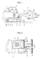
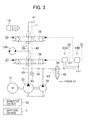
- Figs. 1 and 2 are a side view and a top view showing the overall structure of an electric hydraulic excavator in accordance with an embodiment of the present invention.
- directions “front” (right in Fig. 1 ), “rear” (left in Fig. 1 ), “right” (in front of the sheet of Fig. 1 ) and “left” (behind the sheet of Fig. 1 ) from the viewpoint of the operator seated on the cab seat of the electric hydraulic excavator in the state shown in Fig. 1 will be referred to simply as “front”, “rear”, “right” and “left”, respectively.
- the electric hydraulic excavator (in this embodiment, a mini-excavator whose operating mass is less than 6 tons) comprises a lower travel structure 1 of the crawler type, an upper rotating structure 2 mounted on the lower travel structure 1 to be rotatable, a rotation frame 3 forming the base structure of the upper rotating structure 2, a swing post 4 mounted on a front part of the rotation frame 3 to be able to rotate (swing) left and right, a multijoint work implement 5 connected to the swing post 4 to be rotatable (elevatable) in the vertical direction, a cab 6 of the canopy type formed on the rotation frame 3, and a battery device storage part 8 formed on a rear part of the rotation frame 3 to store a battery device 7 (see Figs. 3 , 4 and 6 which will be explained later).
- the lower travel structure 1 includes a track frame 9 in a shape like "H" when viewed from above, left and right driving wheels 10, 10 rotatably supported in the vicinity of the rear ends of left and right side faces of the track frame 9, left and right driven wheels (idlers) 11, 11 rotatably supported in the vicinity of the front ends of the left and right side faces of the track frame 9, and left and right crawlers 12, 12 each stretched between the left/right driving wheel 10 and the left/right driven wheel 11.
- the left driving wheel 10 (the left crawler 12) is driven and rotated by a left travel hydraulic motor 13A (see Fig. 3 which will be explained later), while the right driving wheel 10 (the right crawler 12) is driven and rotated by a right travel hydraulic motor 13B.
- a blade 14 for removing earth is attached to the front of the track frame 9 to be movable up and down.
- the blade 14 is moved up and down by the expansion/contraction of a blade hydraulic cylinder (unshown).
- a rotation wheel 15 is provided at the center of the track frame 9 so that the rotation frame 3 can be rotated via the rotation wheel 15.
- the rotation frame 3 (the upper rotating structure 2) is driven and rotated by a rotation hydraulic motor (unshown).
- the swing post 4 is attached to the front of the rotation frame 3 to be able to rotate (swing) left and right.
- the swing post 4 is rotated (swung) left and right by the expansion/contraction of a swing hydraulic cylinder (unshown), by which the work implement 5 is swung left and right.
- the work implement 5 includes a boom 16 connected to the swing post 4 to be rotatable in the vertical direction, an arm 17 connected to the boom 16 to be rotatable in the vertical direction, and a bucket 18 connected to the arm 17 to be rotatable in the vertical direction.
- the rotations of the boom 16, the arm 17 and the bucket 18 in the vertical direction are implemented by a boom hydraulic cylinder 19, an arm hydraulic cylinder 20 and a bucket hydraulic cylinder 21, respectively.
- the bucket 18 is replaceable with an attachment (unshown) having a built-in option hydraulic actuator, for example.
- the cab 6 is provided with a cab seat (seat) 22, on which the operator is seated.
- Left and right travel control levers 23A and 23B (only the travel control lever 23A is shown in Fig. 3 which will be explained later) operable forward and backward with hands or feet to command the operation of the left and right rotation hydraulic motors 13A and 13B (i.e., the left and right crawlers 12) are arranged in front of the cab seat 22.
- an option control pedal (unshown) to be operated left and right for commanding the operation of the option hydraulic cylinder (i.e., the attachment) is arranged.
- a swing control pedal (unshown) to be operated left and right for commanding the operation of the swing hydraulic cylinder (i.e., the swing post 4) is arranged.
- an arm/rotation control lever 24A (unshown) of the cross-hair four-way operation, which is operable forward and backward to command the operation of the arm hydraulic cylinder 20 (i.e., the arm 17) and operable left and right to command the operation of the rotation hydraulic motor (i.e., the upper rotating structure 2).
- a boom/bucket control lever 24B of the cross-hair four-way operation which is operable forward and backward to command the operation of the boom hydraulic cylinder 19 (i.e., the boom 16) and operable left and right to command the operation of the bucket hydraulic cylinder 21 (i.e., the bucket 18).
- a blade control lever (unshown) operable forward and backward to command the operation of the blade hydraulic cylinder (i.e., the blade 14) is also arranged to the right of the cab seat 22.
- a gate lock lever which is operable between an unlocking position (specifically, a lower position for prohibiting the operator from getting on/off the cab 6) and a locking position (specifically, an upper position for allowing the operator to get on/off the cab 6) is arranged to the left of the cab seat 22 (i.e., at the entrance of the cab 6).
- a key switch 25, a dial 26, a charging switch 27, a selector switch 28, and remaining amount indicators (electric amount indicators) 29A and 29B are arranged to the right of the cab seat 22.
- a monitor 30 is arranged to the front right of the cab seat 22.
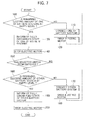
- Fig. 3 is a hydraulic circuit diagram showing the configuration of a hydraulic drive system of the electric hydraulic excavator which has been explained above.
- Fig. 3 illustrates a configuration related to the left travel hydraulic motor 13A and the boom hydraulic cylinder 19 as a representative example.
- the hydraulic drive system includes an electric motor 31, the battery device 7 as the electric power source for the electric motor 31, an inverter device 32 which drives and controls the electric motor 31 by controlling the electric power supplied to the electric motor 31, a hydraulic pump 33 and a pilot pump 34 which are driven by the electric motor 31, an operating device 35 of the hydraulic pilot type which is equipped with the aforementioned left travel control lever 23A, and a left travel directional control valve 36 which controls the flow of the hydraulic fluid from the hydraulic pump 33 to the left travel hydraulic motor 13A according to the operator's forward/backward operation on the left travel control lever 23A.
- the hydraulic drive system further includes an operating device 37 of the hydraulic pilot type which is equipped with the aforementioned boom/bucket control lever 24B and a boom directional control valve 38 which controls the flow of the hydraulic fluid from the hydraulic pump 33 to the boom hydraulic cylinder 19 according to the operator's forward/backward operation on the boom/bucket control lever 24B.
- an operating device 37 of the hydraulic pilot type which is equipped with the aforementioned boom/bucket control lever 24B and a boom directional control valve 38 which controls the flow of the hydraulic fluid from the hydraulic pump 33 to the boom hydraulic cylinder 19 according to the operator's forward/backward operation on the boom/bucket control lever 24B.
- configurations related to the right travel hydraulic motor 13B, the arm hydraulic cylinder 20, the bucket hydraulic cylinder 21, the rotation hydraulic motor, the swing hydraulic cylinder and the blade hydraulic cylinder are substantially equivalent to the configuration shown in Fig. 3 .
- the left travel directional control valve 36, the boom directional control valve 38, etc. are of the center bypass type.
- Each of the directional control valves has a center bypass channel which is situated in a center bypass line 39.
- the center bypass channels of the directional control valves are connected in series in the center bypass line 39.
- the center bypass line 39 is communicated when the spool of each directional control valve is at its neutral position, and interrupted when the spool of a directional control valve is shifted to a switched position on the left-hand side or right-hand side in Fig. 3 .
- the upstream end of the center bypass line 39 is connected to a delivery line 40 of the hydraulic pump 33, while the downstream end of the center bypass line 39 is connected to a tank line 41.
- Each of the left travel directional control valve 36, the boom directional control valve 38, etc. has a signal channel which is situated in a hydraulic signal line 42.
- the signal channels of the directional control valves are connected in series in the hydraulic signal line 42.
- the hydraulic signal line 42 is communicated when the spool of each directional control valve is at its neutral position, and interrupted when the spool of a directional control valve is shifted to a switched position on the left-hand side or right-hand side in Fig. 3 .
- the upstream end of the hydraulic signal line 42 is connected to a delivery line 43 of the pilot pump 34 to branch off from the delivery line 43, while the downstream end of the hydraulic signal line 42 is connected to the tank line 41.
- a fixed restrictor 44 is arranged in a part of the hydraulic signal line 42 upstream of the most upstream directional control valve 36, and a pressure switch 45 (operation detecting means) is arranged between the fixed restrictor 44 and the directional control valve 36.
- the hydraulic pressure upstream of the directional control valve 36 is introduced by the pressure switch 45.
- the pressure switch 45 is closed when the introduced hydraulic pressure reaches a preset threshold value.
- the pressure switch 45 detects whether any one of the directional control valves has been switched or not, that is, whether any one of the hydraulic actuators (specifically, the left travel hydraulic motor 13A, the right travel hydraulic motor 13B, the boom hydraulic cylinder 19, the arm hydraulic cylinder 20, the bucket hydraulic cylinder 21, the rotation hydraulic motor, the swing hydraulic cylinder and the blade hydraulic cylinder) is being operated or not and outputs an ON signal when any one of the hydraulic actuators is being operated.
- the hydraulic actuators specifically, the left travel hydraulic motor 13A, the right travel hydraulic motor 13B, the boom hydraulic cylinder 19, the arm hydraulic cylinder 20, the bucket hydraulic cylinder 21, the rotation hydraulic motor, the swing hydraulic cylinder and the blade hydraulic cylinder
- the left travel directional control valve 36 is switched by pilot pressure supplied from the operating device 35.
- the operating device 35 includes the aforementioned left travel control lever 23A and a pair of pressure reducing valves (unshown) for generating the pilot pressure according to the operator's forward/backward operation on the control lever 23A by use of the delivery pressure of the pilot pump 34 as the source pressure.
- the pilot pressure generated by one of the pilot valves according to the operation amount of the control lever 23A is outputted to a pressure receiving part (right-hand side in Fig. 3 ) of the left travel directional control valve 36, by which the left travel directional control valve 36 is switched to a rightward switched position in Fig. 3 . Consequently, the left travel hydraulic motor 13A rotates in the forward direction, rotating the left driving wheel 10 and the left crawler 12 in the forward direction.
- the pilot pressure generated by the other one of the pilot valves according to the operation amount of the control lever 23A is outputted to a pressure receiving part (left-hand side in Fig. 3 ) of the left travel directional control valve 36, by which the left travel directional control valve 36 is switched to a leftward switched position in Fig. 3 . Consequently, the left travel hydraulic motor 13A rotates in the backward direction, rotating the left driving wheel 10 and the left crawler 12 in the backward direction.
- the boom directional control valve 38 is switched by pilot pressure supplied from the operating device 37.
- the operating device 37 includes the boom/bucket control lever 24B and a pair of pilot valves (unshown) for generating the pilot pressure according to the operator's forward/backward operation on the control lever 24B by use of the delivery pressure of the pilot pump 34 as the source pressure.
- the delivery line 43 of the pilot pump 34 is equipped with a pilot relief valve (unshown) which maintains the delivery pressure of the pilot pump 34 at a constant level.
- the delivery line 43 of the pilot pump 34 is further equipped with a lock valve 46 which is switched according to the operation on the aforementioned gate lock lever. Specifically, a lock switch 47 (see Fig. 4 which will be explained later) which is closed when the gate lock lever is at the unlocking position (lower position) and opened when the gate lock lever is at the locking position (upper position) is employed.
- Fig. 4 is a block diagram showing the configuration of the inverter device 32 in this embodiment together with related devices.
- the inverter device 32 is configured to be able to selectively perform motor driving control (driving the electric motor 31 by supplying electric power from the battery device 7 to the electric motor 31) and battery charging control (charging the battery device 7 by supplying electric power from an external commercial power supply 48 to the battery device 7 when a cable from the commercial power supply 48 is connected).
- the inverter device 32 includes a rectifier 49, a step-up/down unit 50, an inverter 51, control selection switches 52A and 52B, and a calculation control unit 53.
- the rectifier 49 converts AC voltage (200 V) supplied from the commercial power supply 48 into DC voltage when the battery charging control is performed.
- the step-up/down unit 50 has a step-down function of lowering the DC voltage supplied from the rectifier 49 and supplying the lowered DC voltage to the battery device 7 when the battery charging control is performed, and a step-up function of boosting the DC voltage (approximately 200 V) supplied from the battery device 7 up to approximately 300 V when the motor driving control is performed.
- the inverter 51 generates AC voltage based on the DC voltage supplied from the step-up/down unit 50 and supplies the generated AC voltage to the electric motor 31 when the motor driving control is performed.
- the control selection switch 52A (relay of the normally open type) is arranged between the battery device 7 and the step-up/down unit 50.
- the control selection switch 52B (relay of the normally open type) is arranged upstream of the rectifier 49 (i.e., between the commercial power supply 48 and the rectifier 49).
- the step-up/down unit 50 is a step-up/down chopper which is publicly known as a unit of this type.
- the step-up/down unit 50 is made up of switching elements 60a - 60d, diodes 61a - 61d, reactance 62, a current sensor 63 and an electrolytic capacitor 64 as shown in Fig. 5 , for example.
- the calculation control unit 53 of the inverter device 32 is configured to receive signals inputted from the aforementioned key switch 25, dial 26, charging switch 27, selector switch 28, pressure switch 45, lock switch 47, etc. and to be capable of communicating with battery controllers 54A and 54B (explained later) of the battery device 7. Further, the calculation control unit 53 controls the step-up/down unit 50, the inverter 51 and the control selection switches 52A and 52B while also outputting a display signal to the monitor 30.
- the key switch 25 is made up of a key cylinder and a key which can be inserted into the key cylinder.
- the key switch 25 outputs a signal corresponding to the rotational position (OFF position, ON position, or START position) of the key.
- the dial 26 is used for specifying the target revolution speed of the electric motor 31.
- the dial 26 outputs a target revolution speed signal corresponding to its rotational position.
- the charging switch 27 is used for specifying the ON/OFF of the battery charging control.
- the charging switch 27 outputs a signal corresponding to its operational position (OFF position or ON position).
- the calculation control unit 53 of the inverter device 32 starts the motor driving control when the key switch 25 is judged to have been operated to the START position (based on the presence/absence of a signal from the key switch 25) and the gate lock lever is judged to be at the locking position (based on the presence/absence of a signal from the lock switch 47), for example.
- the calculation control unit 53 controls the control selection switches 52A and 52B to shift them to the closed state and the open state, respectively, and outputs a step-up command to the step-up/down unit 50.
- the step-up/down unit 50 boosts the DC voltage (approximately 200 V) supplied from the battery device 7 up to approximately 300 V.
- the calculation control unit 53 also outputs a command of the target revolution speed specified by the dial 26 to the inverter 51. According to the command, the inverter 51 controls the voltage applied to the electric motor 31 so that the actual revolution speed of the electric motor 31 equals the target revolution speed.
- the calculation control unit 53 of the inverter device 32 outputs a command of a preset low revolution speed (idle revolution speed) to the inverter 51 when all the hydraulic actuators are judged to be in the non-operated state (based on the presence/absence of a signal from the pressure switch 45) during the driving of the electric motor 31 and a preset time period (e.g., four seconds) has passed in that state, for example.
- a preset low revolution speed e.g., four seconds
- the calculation control unit 53 of the inverter device 32 outputs a stop command to the inverter 51 when the key switch 25 is judged to have been operated to the OFF position (based on the presence/absence of a signal from the key switch 25) during the driving of the electric motor 31, for example. According to the command, the inverter 51 stops the electric motor 31.
- the calculation control unit 53 of the inverter device 32 performs the battery charging control when the key switch 25 is judged to be at the OFF position (based on the presence/absence of a signal from the key switch 25), the charging switch 27 is judged to have been operated to the ON position (based on the presence/absence of a signal from the charging switch 27), and a cable from the commercial power supply 48 is judged to have been connected (based on the presence/absence of a signal from a cable connection detecting circuit (unshown)), for example.
- the calculation control unit 53 controls the control selection switches 52A and 52B to shift them to the closed state and outputs a step-down command to the step-up/down unit 50. According to the command, the step-up/down unit 50 lowers the DC voltage supplied from the rectifier 49 and supplies the lowered DC voltage to the battery device 7.
- the calculation control unit 53 of the inverter device 32 outputs a stop command to the step-up/down unit 50 when the charging switch 27 is judged to have been operated to the OFF position (based on the presence/absence of a signal from the charging switch 27) during the charging of the battery device 7, for example. According to the command, the step-up/down unit 50 stops the charging.
- Fig. 6 is a block diagram showing the configuration of the battery device 7 in this embodiment together with related devices.
- the battery device 7 includes a first battery system 56A made up a plurality of batteries (i.e., modules) 55 connected in series and a second battery system 56B made up a plurality of batteries 55 connected in series.
- Each battery system 56A, 56B includes nine batteries 55 (only three are shown in Fig. 6 as representatives), for example.
- the battery device 7 further includes a first battery controller 54A corresponding to the first battery system 56A and a second battery controller 54B corresponding to the second battery system 56B.
- each battery 55 includes eight cells (made of lithium ions, etc., for example) and a cell controller for monitoring the cells.
- Each cell controller in the first battery system 56A acquires information on each battery 55 (specifically, state quantities such as voltage and temperature) and outputs the acquired information to the first battery controller 54A.
- the positive terminal (right-hand side in Fig. 6 ) of the first battery system 56A is equipped with a first current sensor 57A and a first connection selection switch 58A (relay of the normally open type).
- the first current sensor 57A detects the electric current of the first battery system 56A and outputs information on the detected electric current to the first battery controller 54A.
- the first battery controller 54A calculates the total voltage of the first battery system 56A based on the voltage information on the batteries 55 acquired from the cell controllers and calculates the remaining electric amount of the first battery system 56A based on the calculated total voltage and the electric current information acquired from the first current sensor 57A. Then, the first battery controller 54A sends the calculated total voltage and remaining electric amount of the first battery system 56A to the calculation control unit 53 of the inverter device 32. Further, the first battery controller 54A judges to which of multiple levels (e.g., 10 levels from level "0" meaning the fully discharged state to level "10" meaning the fully charged state) the remaining electric amount of the first battery system 56A corresponds, and outputs a display signal corresponding to the level to the remaining amount indicator 29A. The remaining amount indicator 29A displays the remaining electric amount of the first battery system 56A in 10 levels by properly switching ON/OFF each segment of a 10-segment bar, for example.
- multiple levels e.g. 10 levels from level "0" meaning the fully discharged state to level
- the first battery controller 54A judges whether an abnormality has occurred in the first battery system 56A or not based on the information on the batteries acquired from the cell controllers. When an abnormality is judged to have occurred, the first battery controller 54A outputs an error signal to the calculation control unit 53 of the inverter device 32.
- each cell controller in the second battery system 56B acquires information on each battery 55 and outputs the acquired information to the second battery controller 54B.
- the positive terminal (right-hand side in Fig. 6 ) of the second battery system 56B is equipped with a second current sensor 57B and a second connection selection switch 58B (relay of the normally open type).
- the second current sensor 57B detects the electric current of the second battery system 56B and outputs information on the detected electric current to the second battery controller 54B.
- the second battery controller 54B calculates the total voltage of the second battery system 56B based on the voltage information on the batteries 55 acquired from the cell controllers and calculates the remaining electric amount of the second battery system 56B based on the calculated total voltage and the electric current information acquired from the second current sensor 57B. Then, the second battery controller 54B sends the calculated total voltage and remaining electric amount of the second battery system 56B to the calculation control unit 53 of the inverter device 32. Further, the second battery controller 54B judges to which of the multiple levels (e.g., 10 levels) the remaining electric amount of the second battery system 56B corresponds, and outputs a display signal corresponding to the level to the remaining amount indicator 29B.
- the remaining amount indicator 29B displays the remaining electric amount of the first battery system 56A in 10 levels by properly switching ON/OFF each segment of a 10-segment bar, for example.
- the second battery controller 54B judges whether an abnormality has occurred in the second battery system 56B or not based on the information on the batteries acquired from the cell controllers. When an abnormality is judged to have occurred, the second battery controller 54B outputs an error signal to the calculation control unit 53 of the inverter device 32.
- the selector switch 28 (see Fig. 4 explained above) is a switch used for selecting one battery system from the first and second battery systems 56A and 56B by manual operation.
- the selector switch 28 outputs a selection signal corresponding to its operational position.
- the calculation control unit 53 of the inverter device 32 controls the first connection selection switch 58A to shift it to the closed state via the first battery controller 54A while controlling the second connection selection switch 58B to shift it to the open state via the second battery controller 54B. Consequently, the first battery system 56A is connected to the step-up/down unit 50 of the inverter device 32.
- the calculation control unit 53 of the inverter device 32 controls the first connection selection switch 58A to shift it to the open state via the first battery controller 54A while controlling the second connection selection switch 58B to shift it to the closed state via the second battery controller 54B. Consequently, the second battery system 56B is connected to the step-up/down unit 50 of the inverter device 32.
- Fig. 7 is a flow chart showing the process flow of the motor driving control in this embodiment.
- step 100 the calculation control unit 53 of the inverter device 32 judges whether or not the remaining electric amount of the first battery system 56A is at the empty level (i.e., whether the first battery system 56A has reached the fully discharged state).
- step 100: NO the process advances to step 110.
- the calculation control unit 53 sends a closing command signal to the first battery controller 54A while sending an opening command signal to the second battery controller 54B.
- the first battery controller 54A controls the first connection selection switch 58A to shift it to the closed state and the second battery controller 54B controls the second connection selection switch 58B to shift it to the open state. Consequently, the first battery system 56A is connected to the step-up/down unit 50 of the inverter device 32.
- step 120 in which the calculation control unit 53 of the inverter device 32 outputs the step-up command to the step-up/down unit 50 while also outputting the target revolution speed command to the inverter 51. Consequently, the DC voltage supplied from the first battery system 56A is boosted by the step-up/down unit 50 and AC voltage generated by the inverter 51 based on the boosted DC voltage is supplied to the electric motor 31 to drive the electric motor 31.
- the calculation control unit 53 of the inverter device 32 commands the monitor 30 to indicate that the first battery system 56A is discharging electricity based on the signal of the detection explained above.
- the steps 110 and 120 are repeated, that is, the driving of the electric motor 31 (i.e., the discharging of the first battery system 56A) is continued.
- the calculation control unit 53 outputs the stop command to the step-up/down unit 50 and the inverter 51 and thereby stops the electric motor 31.
- the calculation control unit 53 outputs an error display signal to the monitor 30 and a drive signal to a buzzer. Accordingly, an abnormality display lamp on the monitor 30 turns ON and the buzzer sounds.
- step 130 the calculation control unit 53 of the inverter device 32 outputs a full discharge display signal to the remaining amount indicator 29A via the first battery controller 54A.
- the remaining amount indicator 29A blinks only the two segments at both ends of the 10-segment bar, for example.
- step 140 the calculation control unit 53 of the inverter device 32 outputs the stop command to the inverter 51 and thereby stops the electric motor 31 (motor stopping means).
- the calculation control unit 53 outputs the drive signal to the buzzer. Accordingly, the buzzer sounds.
- step 150 the process advances to step 150 and whether the second battery system 56B has been selected by operating the selector switch 28 or not is judged based on the selection signal from the selector switch 28.
- step 150: NO the process returns to the step 140 and the same procedure is repeated.
- step 160 the calculation control unit 53 of the inverter device 32 judges whether or not the remaining electric amount of the first battery system 56A is at the empty level (i.e., whether the second battery system 56B has reached the fully discharged state).
- step 160: NO the process advances to step 170.
- the calculation control unit 53 sends the opening command signal to the first battery controller 54A while sending the closing command signal to the second battery controller 54B.
- the first battery controller 54A controls the first connection selection switch 58A to shift it to the open state and the second battery controller 54B controls the second connection selection switch 58B to shift it to the closed state. Consequently, the second battery system 56B is connected to the step-up/down unit 50 of the inverter device 32.
- step 180 in which the calculation control unit 53 of the inverter device 32 outputs the step-up command to the step-up/down unit 50 while also outputting the target revolution speed command to the inverter 51. Consequently, the DC voltage supplied from the second battery system 56B is boosted by the step-up/down unit 50 and AC voltage generated by the inverter 51 based on the boosted DC voltage is supplied to the electric motor 31 to drive the electric motor 31. In this case, the calculation control unit 53 of the inverter device 32 commands the monitor 30 to indicate that the second battery system 56B is discharging electricity.
- the steps 170 and 180 are repeated, that is, the driving of the electric motor 31 (i.e., the discharging of the second battery system 56B) is continued.
- the calculation control unit 53 outputs the stop command to the step-up/down unit 50 and the inverter 51 and thereby stops the electric motor 31.
- the calculation control unit 53 outputs the error display signal to the monitor 30 and the drive signal to the buzzer. Accordingly, the abnormality display lamp on the monitor 30 turns ON and the buzzer sounds.
- step 190 the calculation control unit 53 of the inverter device 32 outputs the full discharge display signal to the remaining amount indicator 29B via the second battery controller 54B.
- the remaining amount indicator 29B blinks only the two segments at both ends of the 10-segment bar, for example.
- step 200 the calculation control unit 53 of the inverter device 32 outputs the stop command to the inverter 51 and thereby stops the electric motor 31 (motor stopping means).
- the calculation control unit 53 outputs the drive signal to the buzzer. Accordingly, the buzzer sounds.
- Fig. 8 is a flow chart showing the process flow of the battery charging control in this embodiment.
- V 1 in this embodiment, 4.15 V (upper limit voltage of each cell)
- ⁇ 8 the number of cells of each battery
- ⁇ 9 the number of batteries of the first battery system 56A
- step 220 the calculation control unit 53 sends the closing command signal to the first battery controller 54A while sending the opening command signal to the second battery controller 54B.
- the first battery controller 54A controls the first connection selection switch 58A to shift it to the closed state and the second battery controller 54B controls the second connection selection switch 58B to shift it to the open state. Consequently, the first battery system 56A is connected to the step-up/down unit 50 of the inverter device 32.
- step 230 in which the calculation control unit 53 of the inverter device 32 performs constant-current charging on the first battery system 56A.
- the switching elements 60a - 60d of the step-up/down unit 50 are ON/OFF controlled and the charging current reaches the preset value A 1 .
- the calculation control unit 53 of the inverter device 32 commands the monitor 30 to indicate that the first battery system 56A is being charged.
- the steps 220 and 230 are repeated until the judgment of the step 210 turns negative. In other words, the constant-current charging of the first battery system 56A is continued until the total voltage of the first battery system 56A reaches the upper limit value V 1 .
- step 250 the calculation control unit 53 sends the opening command signal to the first battery controller 54A while sending the closing command signal to the second battery controller 54B.
- the first battery controller 54A controls the first connection selection switch 58A to shift it to the open state and the second battery controller 54B controls the second connection selection switch 58B to shift it to the closed state. Consequently, the second battery system 56B is connected to the step-up/down unit 50 of the inverter device 32.
- step 260 in which the calculation control unit 53 of the inverter device 32 performs the constant-current charging on the second battery system 56B.
- the calculation control unit 53 of the inverter device 32 commands the monitor 30 to indicate that the second battery system 56B is being charged.
- the steps 220 and 230 are repeated until the judgment of the step 240 turns negative.
- the constant-current charging of the second battery system 56B is continued until the total voltage of the second battery system 56B reaches the upper limit value V 1 .
- step 270 the calculation control unit 53 of the inverter device 32 performs constant-voltage charging on the connected one of the battery systems (i.e., the second battery system 56B in cases where the process has advanced through the steps 260, 240 and 270, or the first battery system 56B in cases where the process has advanced through the steps 230, 240 and 270).
- the calculation control unit 53 of the inverter device 32 which continuously calculates charging current necessary for keeping the total voltage of the connected battery system at the upper limit value V 1 , outputs a command signal to the step-up/down unit 50 so that the detected value of the charging current equals the calculated value.
- the command signal the switching elements 60a - 60d of the step-up/down unit 50 are ON/OFF controlled and the charging current reaches the calculated value.
- the calculation control unit 53 of the inverter device 32 commands the monitor 30 to indicate that the one of the battery systems (connected battery system) is being charged.
- the aforementioned step 270 is repeated. In other words, the constant-voltage charging of the one of the battery systems is continued until the battery system reaches the fully charged state.
- step 290 the connection is switched to the other battery system. Thereafter, the process advances to step 300, in which the calculation control unit 53 of the inverter device 32 performs the constant-voltage charging on the other battery system. In this case, the calculation control unit 53 of the inverter device 32 commands the monitor 30 to indicate that the other battery system is being charged.
- step 310 in which the calculation control unit 53 judges whether or not the other battery system has reached the fully charged state.
- step 310 NO
- the aforementioned step 300 is repeated.
- the constant-voltage charging of the other battery system is continued until the other battery system reaches the fully charged state.
- step 310: YES the charging control is ended.
- Fig. 9 is a time chart for explaining the battery device charging operation in this embodiment.
- Fig. 10 is a time chart for explaining the battery device charging operation in the comparative example. Both of Figs. 9 and 10 indicate temporal changes of the voltages and the charging currents of the first and second battery systems 56A and 56B.
- the first battery system 56A is charged first by the constant-current charging by selectively connecting the first battery system 56A.
- the connection is switched to the second battery system 56B and the second battery system 56B is charged by the constant-current charging.
- the second battery system 56B is charged by the constant-voltage charging.
- the connection is switched to the first battery system 56A and the first battery system 56A is charged by the constant-voltage charging.
- the first battery system 56A is charged to the fully charged state and thereafter the second battery system 56B is charged as shown in Fig. 10 .
- the first battery system 56A is charged first by the constant-current charging by selectively connecting the first battery system 56A.
- the first battery system 56A is charged by the constant-voltage charging.
- the connection is switched to the second battery system 56B and the second battery system 56B is charged by the constant-current charging.
- the second battery system 56B is charged by the constant-voltage charging.
- this embodiment is capable of increasing the charging rate of the battery device 7 in cases where a sufficient charging time for charging both of the battery systems 56A and 56B to the fully charged state cannot be secured (i.e., when the charging time is short like the illustrated period till time t1 - t3).
- the comparative example performs the charging according to the control procedure of (constant-voltage charging of the first battery system 56A) to (constant-current charging of the second battery system 56B), whereas this embodiment performs the charging according to the control procedure of (constant-current charging of the second battery system 56B) to (constant-voltage charging of the second battery system 56B).
- the charging current and the charging efficiency are lower in the constant-voltage charging compared to those in the constant-current charging. Furthermore, even during the constant-voltage charging, the charging current decreases and the charging efficiency drops as the charged battery system approaches the fully charged state. Thus, in the charging period till time t1 - t3, this embodiment is capable of increasing the charging rate of the battery device 7 compared to the comparative example.
- the number of times of switching the connection of the battery systems can be reduced compared to cases employing a control procedure (constant-current charging of the second battery system 56B) to (constant-voltage charging of the first battery system 56A), for example. Therefore, the operating life of the components for the switching of the connection (connection selection switches 58A and 58B) can be increased.
- control procedure constant-current charging of the second battery system 56B
- constant-voltage charging of the second battery system 56B suitable control procedures are not restricted to this example.
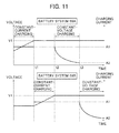
- the control procedure constant-current charging of the second battery system 56B
- constant-voltage charging of the first battery system 56A shown in Fig. 11 may also be employed even though the number of times of switching the battery systems increases compared to the above first embodiment.
- the charging rate of the battery device 7 can be increased in spite of a short charging time similarly to the above embodiment.
- Figs. 12 and 13 Another embodiment of the present invention will be described below referring to Figs. 12 and 13 .
- one battery system is charged by the constant-voltage charging, thereafter the connection is switched to the other battery system before the former battery system reaches the fully charged state, and then the other (latter) battery system is charged by the constant-voltage charging.
- components/elements equivalent to those in the above embodiment are assigned the already used reference characters and repeated explanation thereof is omitted properly.
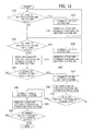
- Fig. 12 is a flow chart showing the process flow of the battery charging control in this embodiment.
- step 320 the calculation control unit 53 of the inverter device 32 judges whether or not the electric current of the connected one of the battery systems has dropped to a preset value A 3 (the electric current value A 1 in the constant-current charging > A 3 > the electric current value A 2 in the fully discharged state).
- the aforementioned step 270 is repeated, that is, the constant-voltage charging of the one of the battery systems is continued.
- step 320 when the electric current of the one of the battery systems has dropped to the preset value A 3 (step 320: YES), the process advances to the step 290 and the connection is switched to the other battery system. Thereafter, the process advances to the step 300, in which the calculation control unit 53 of the inverter device 32 performs the constant-voltage charging on the other battery system.
- step 310 in which the calculation control unit 53 judges whether or not the other battery system has reached the fully charged state.
- step 310 NO
- the aforementioned step 300 is repeated. In other words, the constant-voltage charging of the other battery system is continued until the other battery system reaches the fully charged state.
- step 330 the connection is switched to the former battery system. Thereafter, the process advances to step 340, in which the calculation control unit 53 of the inverter device 32 performs the constant-voltage charging on the former battery system.
- step 280 in which the calculation control unit 53 judges whether or not the former battery system has reached the fully charged state.
- step 280: NO the aforementioned step 340 is repeated. In other words, the constant-voltage charging of the former battery system is continued until the battery system reaches the fully charged state.
- step 280: YES the charging control is ended.
- Fig. 13 is a time chart for explaining the battery device charging operation in this embodiment.
- the first battery system 56A is charged first by the constant-current charging by selectively connecting the first battery system 56A.
- the connection is switched to the second battery system 56B and the second battery system 56B is charged by the constant-current charging.
- the second battery system 56B is charged by the constant-voltage charging.
- the connection is switched to the first battery system 56A and the first battery system 56A is charged by the constant-voltage charging.
- the connection is switched to the second battery system 56B and the second battery system 56B is charged by the constant-voltage charging.
- the charging rate can be increased in spite of a short charging time similarly to the above embodiment. Furthermore, the charging rate can be increased further by this embodiment when the charging time is short (like the illustrated period till time t5 - t6) even though the number of times of switching the connection of the battery systems increases compared to the above embodiment.
- the inverter device 32 is configured to be able to selectively perform the motor driving control for driving the electric motor 31 by supplying the electric power from the battery device 7 to the electric motor 31 (first control mode) and the battery charging control for charging the battery device 7 by supplying the electric power from the commercial power supply 48 to the battery device 7 when a cable from the external commercial power supply 48 is connected (second control mode) depending on the operation on the key switch 25 and the charging switch 27, and to perform control procedures like (constant-current charging of the battery system 56A) to (constant-current charging of the battery system 56B) in the second control mode, for example.
- the control modes and procedures are not restricted to these examples.
- the inverter device 32 may also be configured to be able to selectively perform the aforementioned first control mode, the aforementioned second control mode, a third control mode for driving the electric motor 31 by supplying the electric power from the commercial power supply 48 to the electric motor 31, and a fourth control mode for driving the electric motor 31 while charging the battery device 7 by supplying the electric power from the commercial power supply 48 to the electric motor 31 and the battery device 7, depending on the operation on the key switch 25, the charging switch 27 and a mode selection switch (unshown), and to perform control procedures like (constant-current charging of the battery system 56A) to (constant-current charging of the battery system 56B) in the fourth control mode, for example. Also in this case, effects equivalent to the aforementioned effects can be achieved.
- the battery system 56A is charged by the constant-current charging, the connection is switched to the battery system 56B immediately after the voltage of the battery system 56A reaches the upper limit value, and then the battery system 56B is charged by the constant-current charging.
- the procedure for the charging is not restricted to this example.
- the battery system 56A by the constant-current charging
- charge the battery system 56A by the constant-voltage charging when the voltage of the battery system 56A has reached the upper limit value
- switch the connection to the battery system 56B before the battery system 56A reaches the fully charged state i.e., when the current of the battery system 56A has dropped to the preset value A 3
- charge the battery system 56B by the constant-current charging.
- the charging rate of the battery device 7 can be increased even though the achieved effects are weaker compared to the above embodiments, etc.
- connection is switched to the other battery system by the manual operation on the selector switch 28 in the above embodiments, etc. when the electric motor 31 stops due to the drop in the remaining electric amount of the connected battery system to the empty level
- the switching may also be performed differently. For example, it is also possible to switch the battery system automatically when a preset time period has passed since the stoppage of the electric motor 31 caused by the drop in the remaining electric amount of the connected battery system to the empty level.
- the battery systems 56A and 56B of the battery device 7 are configured to have the same number of batteries 55 in the above embodiments, etc., the battery systems 56A and 56B may be configured differently. As a specific example, it is possible to form the first battery system 56A with twelve batteries 55 connected in series and the second battery system 56B with six batteries 55 connected in series.
- the battery device 7 includes two battery systems 56A and 56B in the above embodiments, etc., the battery device 7 may include three or more battery systems. As a specific example, the battery device 7 may include three battery systems each having six batteries 55 connected in series.
- the electric hydraulic excavator as a target of application of the present invention is equipped with the left and right travel hydraulic motors 13A and 13B, the rotation hydraulic motor, etc. as the hydraulic actuators other than those for the work implement (the boom hydraulic cylinder 19, the arm hydraulic cylinder 20 and the bucket hydraulic cylinder 21) in the above explanation, the electric hydraulic excavator may also be configured differently.
- the electric hydraulic excavator may be equipped with left and right travel electric motors driven by the electric power supplied from the battery device 7 instead of the left and right travel hydraulic motors 13A and 13B.
- the electric hydraulic excavator may also be equipped with a rotation electric motor driven by the electric power supplied from the battery device 7 instead of the rotation hydraulic motor.
- the present invention is applicable also to middle-sized electric hydraulic excavators on condition that the electric power required by the electric motor(s) is reduced or the electric power supplied by the batteries is increased by technological progress or other factors. Further, it goes without saying that the present invention is applicable not only to electric hydraulic excavators but also to other types of electric construction machines.
Landscapes
- Engineering & Computer Science (AREA)
- Power Engineering (AREA)
- Transportation (AREA)
- Mechanical Engineering (AREA)
- Life Sciences & Earth Sciences (AREA)
- Sustainable Development (AREA)
- Sustainable Energy (AREA)
- Electrochemistry (AREA)
- Chemical & Material Sciences (AREA)
- Chemical Kinetics & Catalysis (AREA)
- Manufacturing & Machinery (AREA)
- General Chemical & Material Sciences (AREA)
- Mining & Mineral Resources (AREA)
- Civil Engineering (AREA)
- General Engineering & Computer Science (AREA)
- Structural Engineering (AREA)
- Operation Control Of Excavators (AREA)
- Electric Propulsion And Braking For Vehicles (AREA)
- Charge And Discharge Circuits For Batteries Or The Like (AREA)
- Secondary Cells (AREA)
Abstract
Description
- The present invention relates to an electric construction machine such as an electric hydraulic excavator, and in particular, to an electric construction machine equipped with a battery device as the electric power source for the electric motor.
- An electric hydraulic excavator as a type of the electric construction machine comprises a hydraulic pump which is driven by an electric motor, a plurality of hydraulic actuators (specifically, a boom hydraulic cylinder, an arm hydraulic cylinder, a bucket hydraulic cylinder, etc.), a plurality of directional control valves which respectively control the flow of hydraulic fluid from the hydraulic pump to the hydraulic actuators, and operating means for respectively operating the directional control valves (e.g., a plurality of operating devices each outputting pilot pressure corresponding to the operational position of a control lever), for example.
- Among such electric hydraulic excavators, there have been known those equipped with a battery as the electric power source for the electric motor. The battery is made of materials such as lithium ions and includes minimum units called "cells". The commercially available final form of the battery is a "module" including a plurality of cells in one package. An electric hydraulic excavator described in
Patent Literature 1 is equipped with a battery device that is made up of a plurality of modules (i.e., a plurality of batteries). - Patent Literature 1:
JP,A 2008-44408 - Although not specifically described in the
Patent Literature 1, in the illustrated middle-sized electric hydraulic excavator (operating mass ≥ 6 tons), all the batteries are connected in series and the electric motor is driven by electric power supplied from all the batteries since the electric power required by the electric motor is relatively high. In other words, the electric hydraulic excavator has only one battery system and uses all the batteries simultaneously. Such a middle-sized electric hydraulic excavator is generally operated in a place close to a charging spot/facility. In contrast, a small-sized electric hydraulic excavator (operating mass < 6 tons) is often operated in a place distant from a charging spot/facility (e.g., tunneling work). Thus, when the remaining electric amount (battery level) of the battery device is low and the battery charging is necessary, the electric hydraulic excavator is required to travel by itself (with its own power) to a charging spot or to the bed of a transporter (e.g., truck) so as to be transported to a charging facility. If the remaining electric amount of every one of the batteries drops to the empty level while the operator is unaware of the situation, the electric hydraulic excavator stops on the spot and the battery charging becomes difficult since the excavator is incapable of traveling by itself. - In consideration of the above-described situation, the present inventors propose a configuration in which the battery device is made up of a plurality of battery systems, one of the battery systems is selectively connected, and DC power from the connected battery system is converted by an inverter into AC power and supplied to the electric motor (in short, the simultaneous use of all the batteries is avoided) based on the viewpoint that the electric power required by the electric motor is relatively low in a small-sized electric hydraulic excavator, for example. With such a configuration, even if the electric hydraulic excavator stops due to the drop in the remaining electric amount of one battery system in use to the empty level, the electric hydraulic excavator can be activated again by switching the connection to another battery system. Accordingly, the electric hydraulic excavator is enabled to travel by itself and the difficulty in the battery charging is eliminated. Further, the operator is allowed to feel and recognize the operating time of the excavator during which one battery system shifts from a prescribed charged state to the fully discharged state. Accordingly, the estimation of the time between the switching of the battery system and the exhaustion of the battery system becomes easy and that facilitates the planning of the charging timing.
- Incidentally, it is generally known that the charging voltage and the charging current are limited in batteries of the lithium ion type and the charging of such batteries should be carried out according to the constant-current/constant-voltage method. The constant-current/constant-voltage method is a method of first charging the battery by constant-current charging while the voltage of the battery is less than an upper limit value and thereafter charging the battery by constant-voltage charging when the voltage has reached the upper limit value (e.g., approximately 4.1 - 4.2 V per cell). For the charging of the aforementioned battery device including a plurality of battery systems, the following procedure can be employed, for example: When the voltages of one battery system (former battery system) and another battery system (latter battery system) are less than the upper limit value, for example, it is possible to charge the former battery system by the constant-current charging, charge the former battery system by the constant-voltage charging when the voltage of the former battery system has reached the upper limit value, switch the connection to the latter battery system when the former battery system has reached the fully charged state, charge the latter battery system by the constant-current charging, and charge the latter battery system by the constant-voltage charging to the fully charged state when the voltage of the latter battery system has reached the upper limit value.
- However, the charging time necessary for charging all the battery systems to the fully charged state is considerably long and it is sometimes difficult to secure such a long charging time. In such a situation, there is a request for increasing the charging rate of the battery device in spite of a short charging time (e.g., battery charging during an intermission between operations).
- It is therefore the primary object of the present invention to provide an electric construction machine capable of increasing the charging rate of the battery device in spite of a short charging time.
-
- (1) To achieve the above object, the present invention provides an electric construction machine comprising: an electric motor; a hydraulic pump driven by the electric motor; a plurality of hydraulic actuators driven by hydraulic fluid delivered from the hydraulic pump; a battery device including a plurality of battery systems each having a plurality of batteries connected in series; connection switching means for selectively connecting one of the battery systems; and an inverter for converting DC power supplied from the battery system selectively connected by the connection switching means into AC power and supplying the AC power to the electric motor. The electric construction machine comprises charging control means which supplies electric power from an external power supply to the battery system selectively connected by the connection switching means, performs constant-current charging when the voltage of the battery system is less than a preset upper limit value, and performs constant-voltage charging when the voltage of the battery system has reached the upper limit value. When the voltages of one battery system (former battery system) and another battery system (latter battery system) included in the plurality of battery systems are less than the upper limit value, the charging control means makes the connection switching means selectively connect the former battery system, starts the constant-current charging of the former battery system, thereafter makes the connection switching means switch the connection to the latter battery system before the former battery system reaches a fully charged state, and then starts the constant-current charging of the latter battery system.
As a comparative example, it is possible to first charge the former battery system to the fully charged state and thereafter charge the latter battery system. In contrast to such a comparative example, the present invention is capable of increasing the charging rate in cases where it is impossible to secure a sufficient charging time for charging all the battery systems to the fully charged state (i.e., when the charging time is short). Specifically, the charging current and the charging efficiency (i.e., the amount of charging per unit time) are generally lower in the constant-voltage charging compared to those in the constant-current charging. Further, even during the constant-voltage charging, the charging current decreases and the charging efficiency drops as the charged battery system approaches the fully charged state. Thus, charging the latter battery system (farther from the fully charged state) is more advantageous for increasing the charging efficiency than charging the former battery system (closer to the fully charged state). Therefore, the electric construction machine in accordance with the present invention is capable of increasing the charging rate of the battery device in spite of a short charging time. - (2) Preferably, in the above electric construction machine (1), when the voltages of one battery system and another battery system included in the plurality of battery systems are less than the upper limit value, the charging control means makes the connection switching means selectively connect the former battery system, charges the former battery system by the constant-current charging, makes the connection switching means switch the connection to the latter battery system immediately after the voltage of the former battery system reaches the upper limit value, and then starts the constant-current charging of the latter battery system.
- (3) Preferably, in the above electric construction machine (2), when the voltages of one battery system and another battery system included in the plurality of battery systems are less than the upper limit value, the charging control means makes the connection switching means selectively connect the former battery system, charges the former battery system by the constant-current charging, makes the connection switching means switch the connection to the latter battery system immediately after the voltage of the former battery system reaches the upper limit value, charges the latter battery system by the constant-current charging, and charges the latter battery system by the constant-voltage charging when the voltage of the latter battery system has reached the upper limit value.
As a comparative example, it is possible to charge the former battery system by the constant-current charging, switch the connection to the latter battery system immediately after the voltage of the former battery system reaches the upper limit value, charge the latter battery system by the constant-current charging, switch the connection to the former battery system immediately after the voltage of the latter battery system reaches the upper limit value, and then charge the former battery system by the constant-voltage charging. Compared to such a comparative example, the present invention is capable of reducing the number of times of switching the connection of the battery systems and increasing the operating life of the components for the switching of the connection. - (4) Preferably, in any one of the above electric construction machines (1) - (3), the charging control means makes the connection switching means selectively connect one of the former and latter battery systems, charges the connected battery system by the constant-voltage charging, thereafter makes the connection switching means switch the connection to the other one of the former and latter battery systems before the connected battery system reaches the fully charged state, and charges the other one of the former and latter battery systems by the constant-voltage charging.
- According to the present invention, the charging rate of the battery device can be increased in spite of a short charging time.
-
-
Fig. 1 is a side view showing the overall structure of an electric hydraulic excavator in accordance with an embodiment of the present invention. -
Fig. 2 is a top view showing the overall structure of the electric hydraulic excavator in accordance with the embodiment of the present invention. -
Fig. 3 is a hydraulic circuit diagram showing the configuration of a hydraulic drive system in the embodiment of the present invention. -
Fig. 4 is a block diagram showing the configuration of an inverter device in the embodiment of the present invention together with related devices. -
Fig. 5 is an electric circuit diagram showing the configuration of a step-up/down unit in the embodiment of the present invention. -
Fig. 6 is a block diagram showing the configuration of a battery device in the embodiment of the present invention together with related devices. -
Fig. 7 is a flow chart showing the process flow of motor driving control in the embodiment of the present invention. -
Fig. 8 is a flow chart showing the process flow of battery charging control in the embodiment of the present invention. -
Fig. 9 is a time chart for explaining a battery device charging operation in the embodiment of the present invention. -
Fig. 10 is a time chart for explaining the battery device charging operation in a comparative example. -
Fig. 11 is a time chart for explaining a battery device charging operation in a modified example of the present invention. -
Fig. 12 is a flow chart showing the process flow of the battery charging control in another embodiment of the present invention. -
Fig. 13 is a time chart for explaining the battery device charging operation in the embodiment of the present invention. - In the following, an embodiment of the present invention will be described with reference to figures by taking an electric hydraulic excavator as an example of the target of application of the present invention.
-
Figs. 1 and 2 are a side view and a top view showing the overall structure of an electric hydraulic excavator in accordance with an embodiment of the present invention. In the following explanation, directions "front" (right inFig. 1 ), "rear" (left inFig. 1 ), "right" (in front of the sheet ofFig. 1 ) and "left" (behind the sheet ofFig. 1 ) from the viewpoint of the operator seated on the cab seat of the electric hydraulic excavator in the state shown inFig. 1 will be referred to simply as "front", "rear", "right" and "left", respectively. - Referring to
Figs. 1 and 2 , the electric hydraulic excavator (in this embodiment, a mini-excavator whose operating mass is less than 6 tons) comprises alower travel structure 1 of the crawler type, an upper rotatingstructure 2 mounted on thelower travel structure 1 to be rotatable, arotation frame 3 forming the base structure of the upper rotatingstructure 2, aswing post 4 mounted on a front part of therotation frame 3 to be able to rotate (swing) left and right, a multijoint work implement 5 connected to theswing post 4 to be rotatable (elevatable) in the vertical direction, acab 6 of the canopy type formed on therotation frame 3, and a batterydevice storage part 8 formed on a rear part of therotation frame 3 to store a battery device 7 (seeFigs. 3 ,4 and6 which will be explained later). - The
lower travel structure 1 includes atrack frame 9 in a shape like "H" when viewed from above, left andright driving wheels track frame 9, left and right driven wheels (idlers) 11, 11 rotatably supported in the vicinity of the front ends of the left and right side faces of thetrack frame 9, and left andright crawlers driving wheel 10 and the left/right drivenwheel 11. The left driving wheel 10 (the left crawler 12) is driven and rotated by a left travelhydraulic motor 13A (seeFig. 3 which will be explained later), while the right driving wheel 10 (the right crawler 12) is driven and rotated by a right travelhydraulic motor 13B. - A
blade 14 for removing earth is attached to the front of thetrack frame 9 to be movable up and down. Theblade 14 is moved up and down by the expansion/contraction of a blade hydraulic cylinder (unshown). - A
rotation wheel 15 is provided at the center of thetrack frame 9 so that therotation frame 3 can be rotated via therotation wheel 15. The rotation frame 3 (the upper rotating structure 2) is driven and rotated by a rotation hydraulic motor (unshown). - The
swing post 4 is attached to the front of therotation frame 3 to be able to rotate (swing) left and right. Theswing post 4 is rotated (swung) left and right by the expansion/contraction of a swing hydraulic cylinder (unshown), by which the work implement 5 is swung left and right. - The work implement 5 includes a
boom 16 connected to theswing post 4 to be rotatable in the vertical direction, anarm 17 connected to theboom 16 to be rotatable in the vertical direction, and abucket 18 connected to thearm 17 to be rotatable in the vertical direction. The rotations of theboom 16, thearm 17 and thebucket 18 in the vertical direction are implemented by a boomhydraulic cylinder 19, an armhydraulic cylinder 20 and a buckethydraulic cylinder 21, respectively. Incidentally, thebucket 18 is replaceable with an attachment (unshown) having a built-in option hydraulic actuator, for example. - The
cab 6 is provided with a cab seat (seat) 22, on which the operator is seated. Left and right travel control levers 23A and 23B (only the travel control lever 23A is shown inFig. 3 which will be explained later) operable forward and backward with hands or feet to command the operation of the left and right rotationhydraulic motors cab seat 22. On the floor to the left of the left travel control lever 23A, an option control pedal (unshown) to be operated left and right for commanding the operation of the option hydraulic cylinder (i.e., the attachment) is arranged. On the floor to the right of the right travel control lever 23B, a swing control pedal (unshown) to be operated left and right for commanding the operation of the swing hydraulic cylinder (i.e., the swing post 4) is arranged. - Arranged to the left of the
cab seat 22 is an arm/rotation control lever 24A (unshown) of the cross-hair four-way operation, which is operable forward and backward to command the operation of the arm hydraulic cylinder 20 (i.e., the arm 17) and operable left and right to command the operation of the rotation hydraulic motor (i.e., the upper rotating structure 2). Arranged to the right of thecab seat 22 is a boom/bucket control lever 24B of the cross-hair four-way operation, which is operable forward and backward to command the operation of the boom hydraulic cylinder 19 (i.e., the boom 16) and operable left and right to command the operation of the bucket hydraulic cylinder 21 (i.e., the bucket 18). A blade control lever (unshown) operable forward and backward to command the operation of the blade hydraulic cylinder (i.e., the blade 14) is also arranged to the right of thecab seat 22. - Further, a gate lock lever which is operable between an unlocking position (specifically, a lower position for prohibiting the operator from getting on/off the cab 6) and a locking position (specifically, an upper position for allowing the operator to get on/off the cab 6) is arranged to the left of the cab seat 22 (i.e., at the entrance of the cab 6). A
key switch 25, adial 26, a chargingswitch 27, aselector switch 28, and remaining amount indicators (electric amount indicators) 29A and 29B (seeFigs. 4 and6 which will be explained later) are arranged to the right of thecab seat 22. Amonitor 30 is arranged to the front right of thecab seat 22. -
Fig. 3 is a hydraulic circuit diagram showing the configuration of a hydraulic drive system of the electric hydraulic excavator which has been explained above.Fig. 3 illustrates a configuration related to the left travelhydraulic motor 13A and the boomhydraulic cylinder 19 as a representative example. - Referring to
Fig. 3 , the hydraulic drive system includes anelectric motor 31, thebattery device 7 as the electric power source for theelectric motor 31, aninverter device 32 which drives and controls theelectric motor 31 by controlling the electric power supplied to theelectric motor 31, ahydraulic pump 33 and apilot pump 34 which are driven by theelectric motor 31, an operatingdevice 35 of the hydraulic pilot type which is equipped with the aforementioned left travel control lever 23A, and a left traveldirectional control valve 36 which controls the flow of the hydraulic fluid from thehydraulic pump 33 to the left travelhydraulic motor 13A according to the operator's forward/backward operation on the left travel control lever 23A. The hydraulic drive system further includes an operatingdevice 37 of the hydraulic pilot type which is equipped with the aforementioned boom/bucket control lever 24B and a boomdirectional control valve 38 which controls the flow of the hydraulic fluid from thehydraulic pump 33 to the boomhydraulic cylinder 19 according to the operator's forward/backward operation on the boom/bucket control lever 24B. Although not shown inFig. 3 , configurations related to the right travelhydraulic motor 13B, the armhydraulic cylinder 20, the buckethydraulic cylinder 21, the rotation hydraulic motor, the swing hydraulic cylinder and the blade hydraulic cylinder are substantially equivalent to the configuration shown inFig. 3 . - The left travel
directional control valve 36, the boomdirectional control valve 38, etc. (specifically, including a right travel directional control valve, an arm directional control valve, a bucket directional control valve, a rotation directional control valve, a swing directional control valve and a blade directional control valve which are not illustrated) are of the center bypass type. Each of the directional control valves has a center bypass channel which is situated in acenter bypass line 39. The center bypass channels of the directional control valves are connected in series in thecenter bypass line 39. Thecenter bypass line 39 is communicated when the spool of each directional control valve is at its neutral position, and interrupted when the spool of a directional control valve is shifted to a switched position on the left-hand side or right-hand side inFig. 3 . The upstream end of thecenter bypass line 39 is connected to adelivery line 40 of thehydraulic pump 33, while the downstream end of thecenter bypass line 39 is connected to atank line 41. - Each of the left travel
directional control valve 36, the boomdirectional control valve 38, etc. has a signal channel which is situated in ahydraulic signal line 42. Specifically, the signal channels of the directional control valves are connected in series in thehydraulic signal line 42. Thehydraulic signal line 42 is communicated when the spool of each directional control valve is at its neutral position, and interrupted when the spool of a directional control valve is shifted to a switched position on the left-hand side or right-hand side inFig. 3 . The upstream end of thehydraulic signal line 42 is connected to adelivery line 43 of thepilot pump 34 to branch off from thedelivery line 43, while the downstream end of thehydraulic signal line 42 is connected to thetank line 41. A fixedrestrictor 44 is arranged in a part of thehydraulic signal line 42 upstream of the most upstreamdirectional control valve 36, and a pressure switch 45 (operation detecting means) is arranged between the fixedrestrictor 44 and thedirectional control valve 36. The hydraulic pressure upstream of thedirectional control valve 36 is introduced by thepressure switch 45. Thepressure switch 45 is closed when the introduced hydraulic pressure reaches a preset threshold value. Thus, thepressure switch 45 detects whether any one of the directional control valves has been switched or not, that is, whether any one of the hydraulic actuators (specifically, the left travelhydraulic motor 13A, the right travelhydraulic motor 13B, the boomhydraulic cylinder 19, the armhydraulic cylinder 20, the buckethydraulic cylinder 21, the rotation hydraulic motor, the swing hydraulic cylinder and the blade hydraulic cylinder) is being operated or not and outputs an ON signal when any one of the hydraulic actuators is being operated. - The left travel
directional control valve 36 is switched by pilot pressure supplied from the operatingdevice 35. The operatingdevice 35 includes the aforementioned left travel control lever 23A and a pair of pressure reducing valves (unshown) for generating the pilot pressure according to the operator's forward/backward operation on the control lever 23A by use of the delivery pressure of thepilot pump 34 as the source pressure. - When the control lever 23A is operated forward from its neutral position, for example, the pilot pressure generated by one of the pilot valves according to the operation amount of the control lever 23A is outputted to a pressure receiving part (right-hand side in
Fig. 3 ) of the left traveldirectional control valve 36, by which the left traveldirectional control valve 36 is switched to a rightward switched position inFig. 3 . Consequently, the left travelhydraulic motor 13A rotates in the forward direction, rotating theleft driving wheel 10 and theleft crawler 12 in the forward direction. - In contrast, when the control lever 23A is operated backward from the neutral position, the pilot pressure generated by the other one of the pilot valves according to the operation amount of the control lever 23A is outputted to a pressure receiving part (left-hand side in
Fig. 3 ) of the left traveldirectional control valve 36, by which the left traveldirectional control valve 36 is switched to a leftward switched position inFig. 3 . Consequently, the left travelhydraulic motor 13A rotates in the backward direction, rotating theleft driving wheel 10 and theleft crawler 12 in the backward direction. - The boom
directional control valve 38 is switched by pilot pressure supplied from the operatingdevice 37. The operatingdevice 37 includes the boom/bucket control lever 24B and a pair of pilot valves (unshown) for generating the pilot pressure according to the operator's forward/backward operation on thecontrol lever 24B by use of the delivery pressure of thepilot pump 34 as the source pressure. - When the
control lever 24B is operated forward from its neutral position, for example, the pilot pressure generated by one of the pilot valves according to the operation amount of thecontrol lever 24B is outputted to a pressure receiving part (right-hand side inFig. 3 ) of the boomdirectional control valve 38, by which the boomdirectional control valve 38 is switched to a rightward switched position inFig. 3 . Consequently, the boomhydraulic cylinder 19 contracts and thereby lowers theboom 16. - In contrast, when the
control lever 24B is operated backward from the neutral position, the pilot pressure generated by the other one of the pilot valves according to the operation amount of thecontrol lever 24B is outputted to a pressure receiving part (left-hand side inFig. 3 ) of the boomdirectional control valve 38, by which the boomdirectional control valve 38 is switched to a leftward switched position inFig. 3 . Consequently, the boomhydraulic cylinder 19 expands and thereby raises theboom 16. - The
delivery line 43 of thepilot pump 34 is equipped with a pilot relief valve (unshown) which maintains the delivery pressure of thepilot pump 34 at a constant level. Thedelivery line 43 of thepilot pump 34 is further equipped with alock valve 46 which is switched according to the operation on the aforementioned gate lock lever. Specifically, a lock switch 47 (seeFig. 4 which will be explained later) which is closed when the gate lock lever is at the unlocking position (lower position) and opened when the gate lock lever is at the locking position (upper position) is employed. - When the
lock switch 47 shifts to the closed state, for example, a solenoid part of thelock valve 46 is energized via thelock switch 47, by which thelock valve 46 is switched to a lower switched position inFig. 3 . Consequently, thedelivery line 43 of thepilot pump 34 is communicated and the delivery pressure of thepilot pump 34 is introduced into the operatingdevices - In contrast, when the
lock switch 47 shifts to the open state, the solenoid part of thelock valve 46 is not energized and thelock valve 46 is returned to its neutral position (upper position inFig. 3 ) by the biasing force of a spring, by which thedelivery line 43 of thepilot pump 34 is interrupted. Consequently, no pilot pressure is generated and the hydraulic actuators are prohibited from operating irrespective of operations on the operatingdevices -
Fig. 4 is a block diagram showing the configuration of theinverter device 32 in this embodiment together with related devices. - Referring to
Fig. 4 , theinverter device 32 is configured to be able to selectively perform motor driving control (driving theelectric motor 31 by supplying electric power from thebattery device 7 to the electric motor 31) and battery charging control (charging thebattery device 7 by supplying electric power from an externalcommercial power supply 48 to thebattery device 7 when a cable from thecommercial power supply 48 is connected). - The
inverter device 32 includes arectifier 49, a step-up/downunit 50, aninverter 51,control selection switches calculation control unit 53. Therectifier 49 converts AC voltage (200 V) supplied from thecommercial power supply 48 into DC voltage when the battery charging control is performed. The step-up/downunit 50 has a step-down function of lowering the DC voltage supplied from therectifier 49 and supplying the lowered DC voltage to thebattery device 7 when the battery charging control is performed, and a step-up function of boosting the DC voltage (approximately 200 V) supplied from thebattery device 7 up to approximately 300 V when the motor driving control is performed. Theinverter 51 generates AC voltage based on the DC voltage supplied from the step-up/downunit 50 and supplies the generated AC voltage to theelectric motor 31 when the motor driving control is performed. Thecontrol selection switch 52A (relay of the normally open type) is arranged between thebattery device 7 and the step-up/downunit 50. Thecontrol selection switch 52B (relay of the normally open type) is arranged upstream of the rectifier 49 (i.e., between thecommercial power supply 48 and the rectifier 49). The step-up/downunit 50 is a step-up/down chopper which is publicly known as a unit of this type. The step-up/downunit 50 is made up of switchingelements 60a - 60d,diodes 61a - 61d,reactance 62, acurrent sensor 63 and anelectrolytic capacitor 64 as shown inFig. 5 , for example. - The
calculation control unit 53 of theinverter device 32 is configured to receive signals inputted from the aforementionedkey switch 25, dial 26, chargingswitch 27,selector switch 28,pressure switch 45,lock switch 47, etc. and to be capable of communicating withbattery controllers battery device 7. Further, thecalculation control unit 53 controls the step-up/downunit 50, theinverter 51 and thecontrol selection switches monitor 30. - The
key switch 25 is made up of a key cylinder and a key which can be inserted into the key cylinder. Thekey switch 25 outputs a signal corresponding to the rotational position (OFF position, ON position, or START position) of the key. Thedial 26 is used for specifying the target revolution speed of theelectric motor 31. Thedial 26 outputs a target revolution speed signal corresponding to its rotational position. The chargingswitch 27 is used for specifying the ON/OFF of the battery charging control. The chargingswitch 27 outputs a signal corresponding to its operational position (OFF position or ON position). - The
calculation control unit 53 of theinverter device 32 starts the motor driving control when thekey switch 25 is judged to have been operated to the START position (based on the presence/absence of a signal from the key switch 25) and the gate lock lever is judged to be at the locking position (based on the presence/absence of a signal from the lock switch 47), for example. Specifically, thecalculation control unit 53 controls thecontrol selection switches unit 50. According to the command, the step-up/downunit 50 boosts the DC voltage (approximately 200 V) supplied from thebattery device 7 up to approximately 300 V. Thecalculation control unit 53 also outputs a command of the target revolution speed specified by thedial 26 to theinverter 51. According to the command, theinverter 51 controls the voltage applied to theelectric motor 31 so that the actual revolution speed of theelectric motor 31 equals the target revolution speed. - Further, the
calculation control unit 53 of theinverter device 32 outputs a command of a preset low revolution speed (idle revolution speed) to theinverter 51 when all the hydraulic actuators are judged to be in the non-operated state (based on the presence/absence of a signal from the pressure switch 45) during the driving of theelectric motor 31 and a preset time period (e.g., four seconds) has passed in that state, for example. According to the command, theinverter 51 controls the voltage applied to theelectric motor 31 so that the actual revolution speed of theelectric motor 31 equals the preset low revolution speed. - Furthermore, the
calculation control unit 53 of theinverter device 32 outputs a stop command to theinverter 51 when thekey switch 25 is judged to have been operated to the OFF position (based on the presence/absence of a signal from the key switch 25) during the driving of theelectric motor 31, for example. According to the command, theinverter 51 stops theelectric motor 31. - The
calculation control unit 53 of theinverter device 32 performs the battery charging control when thekey switch 25 is judged to be at the OFF position (based on the presence/absence of a signal from the key switch 25), the chargingswitch 27 is judged to have been operated to the ON position (based on the presence/absence of a signal from the charging switch 27), and a cable from thecommercial power supply 48 is judged to have been connected (based on the presence/absence of a signal from a cable connection detecting circuit (unshown)), for example. Specifically, thecalculation control unit 53 controls thecontrol selection switches unit 50. According to the command, the step-up/downunit 50 lowers the DC voltage supplied from therectifier 49 and supplies the lowered DC voltage to thebattery device 7. - Further, the
calculation control unit 53 of theinverter device 32 outputs a stop command to the step-up/downunit 50 when the chargingswitch 27 is judged to have been operated to the OFF position (based on the presence/absence of a signal from the charging switch 27) during the charging of thebattery device 7, for example. According to the command, the step-up/downunit 50 stops the charging. -
Fig. 6 is a block diagram showing the configuration of thebattery device 7 in this embodiment together with related devices. - Referring to
Fig. 6 , thebattery device 7 includes afirst battery system 56A made up a plurality of batteries (i.e., modules) 55 connected in series and asecond battery system 56B made up a plurality ofbatteries 55 connected in series. Eachbattery system Fig. 6 as representatives), for example. Thebattery device 7 further includes afirst battery controller 54A corresponding to thefirst battery system 56A and asecond battery controller 54B corresponding to thesecond battery system 56B. Although details are not illustrated, eachbattery 55 includes eight cells (made of lithium ions, etc., for example) and a cell controller for monitoring the cells. - Each cell controller in the
first battery system 56A acquires information on each battery 55 (specifically, state quantities such as voltage and temperature) and outputs the acquired information to thefirst battery controller 54A. The positive terminal (right-hand side inFig. 6 ) of thefirst battery system 56A is equipped with a firstcurrent sensor 57A and a firstconnection selection switch 58A (relay of the normally open type). The firstcurrent sensor 57A detects the electric current of thefirst battery system 56A and outputs information on the detected electric current to thefirst battery controller 54A. - The
first battery controller 54A calculates the total voltage of thefirst battery system 56A based on the voltage information on thebatteries 55 acquired from the cell controllers and calculates the remaining electric amount of thefirst battery system 56A based on the calculated total voltage and the electric current information acquired from the firstcurrent sensor 57A. Then, thefirst battery controller 54A sends the calculated total voltage and remaining electric amount of thefirst battery system 56A to thecalculation control unit 53 of theinverter device 32. Further, thefirst battery controller 54A judges to which of multiple levels (e.g., 10 levels from level "0" meaning the fully discharged state to level "10" meaning the fully charged state) the remaining electric amount of thefirst battery system 56A corresponds, and outputs a display signal corresponding to the level to the remainingamount indicator 29A. The remainingamount indicator 29A displays the remaining electric amount of thefirst battery system 56A in 10 levels by properly switching ON/OFF each segment of a 10-segment bar, for example. - Furthermore, the
first battery controller 54A judges whether an abnormality has occurred in thefirst battery system 56A or not based on the information on the batteries acquired from the cell controllers. When an abnormality is judged to have occurred, thefirst battery controller 54A outputs an error signal to thecalculation control unit 53 of theinverter device 32. - Similarly, each cell controller in the
second battery system 56B acquires information on eachbattery 55 and outputs the acquired information to thesecond battery controller 54B. The positive terminal (right-hand side inFig. 6 ) of thesecond battery system 56B is equipped with a secondcurrent sensor 57B and a secondconnection selection switch 58B (relay of the normally open type). The secondcurrent sensor 57B detects the electric current of thesecond battery system 56B and outputs information on the detected electric current to thesecond battery controller 54B. - The
second battery controller 54B calculates the total voltage of thesecond battery system 56B based on the voltage information on thebatteries 55 acquired from the cell controllers and calculates the remaining electric amount of thesecond battery system 56B based on the calculated total voltage and the electric current information acquired from the secondcurrent sensor 57B. Then, thesecond battery controller 54B sends the calculated total voltage and remaining electric amount of thesecond battery system 56B to thecalculation control unit 53 of theinverter device 32. Further, thesecond battery controller 54B judges to which of the multiple levels (e.g., 10 levels) the remaining electric amount of thesecond battery system 56B corresponds, and outputs a display signal corresponding to the level to the remainingamount indicator 29B. The remainingamount indicator 29B displays the remaining electric amount of thefirst battery system 56A in 10 levels by properly switching ON/OFF each segment of a 10-segment bar, for example. - Furthermore, the
second battery controller 54B judges whether an abnormality has occurred in thesecond battery system 56B or not based on the information on the batteries acquired from the cell controllers. When an abnormality is judged to have occurred, thesecond battery controller 54B outputs an error signal to thecalculation control unit 53 of theinverter device 32. - The selector switch 28 (see
Fig. 4 explained above) is a switch used for selecting one battery system from the first andsecond battery systems selector switch 28 outputs a selection signal corresponding to its operational position. - When a selection signal for selecting the
first battery system 56A is inputted from theselector switch 28, thecalculation control unit 53 of theinverter device 32 controls the first connection selection switch 58A to shift it to the closed state via thefirst battery controller 54A while controlling the secondconnection selection switch 58B to shift it to the open state via thesecond battery controller 54B. Consequently, thefirst battery system 56A is connected to the step-up/downunit 50 of theinverter device 32. - In contrast, when a selection signal for selecting the
second battery system 56B is inputted from theselector switch 28, thecalculation control unit 53 of theinverter device 32 controls the first connection selection switch 58A to shift it to the open state via thefirst battery controller 54A while controlling the secondconnection selection switch 58B to shift it to the closed state via thesecond battery controller 54B. Consequently, thesecond battery system 56B is connected to the step-up/downunit 50 of theinverter device 32. - Next, a procedure for the motor driving control will be explained below referring to
Fig. 7. Fig. 7 is a flow chart showing the process flow of the motor driving control in this embodiment. - The following explanation will be given of a case where the
first battery system 56A has been selected with theselector switch 28, for example. Instep 100, thecalculation control unit 53 of theinverter device 32 judges whether or not the remaining electric amount of thefirst battery system 56A is at the empty level (i.e., whether thefirst battery system 56A has reached the fully discharged state). When thefirst battery system 56A has not reached the fully discharged state (step 100: NO), the process advances to step 110. In thestep 110, thecalculation control unit 53 sends a closing command signal to thefirst battery controller 54A while sending an opening command signal to thesecond battery controller 54B. According to the command signals, thefirst battery controller 54A controls the first connection selection switch 58A to shift it to the closed state and thesecond battery controller 54B controls the secondconnection selection switch 58B to shift it to the open state. Consequently, thefirst battery system 56A is connected to the step-up/downunit 50 of theinverter device 32. - Thereafter, the process advances to step 120, in which the
calculation control unit 53 of theinverter device 32 outputs the step-up command to the step-up/downunit 50 while also outputting the target revolution speed command to theinverter 51. Consequently, the DC voltage supplied from thefirst battery system 56A is boosted by the step-up/downunit 50 and AC voltage generated by theinverter 51 based on the boosted DC voltage is supplied to theelectric motor 31 to drive theelectric motor 31. In this case, thecalculation control unit 53 of theinverter device 32 commands themonitor 30 to indicate that thefirst battery system 56A is discharging electricity based on the signal of the detection explained above. - Until the judgment of the
step 100 turns affirmative, thesteps first battery system 56A) is continued. However, when the error signal is received from thebattery controller calculation control unit 53 outputs the stop command to the step-up/downunit 50 and theinverter 51 and thereby stops theelectric motor 31. In this case, thecalculation control unit 53 outputs an error display signal to themonitor 30 and a drive signal to a buzzer. Accordingly, an abnormality display lamp on themonitor 30 turns ON and the buzzer sounds. - In contrast, when the
first battery system 56A has reached the fully discharged state (step 100: YES), the process advances to step 130. In thestep 130, thecalculation control unit 53 of theinverter device 32 outputs a full discharge display signal to the remainingamount indicator 29A via thefirst battery controller 54A. To display the fully discharged state in response to the display signal, the remainingamount indicator 29A blinks only the two segments at both ends of the 10-segment bar, for example. Thereafter, the process advances to step 140, in which thecalculation control unit 53 of theinverter device 32 outputs the stop command to theinverter 51 and thereby stops the electric motor 31 (motor stopping means). In this case, thecalculation control unit 53 outputs the drive signal to the buzzer. Accordingly, the buzzer sounds. - Thereafter, the process advances to step 150 and whether the
second battery system 56B has been selected by operating theselector switch 28 or not is judged based on the selection signal from theselector switch 28. When thesecond battery system 56B has not been selected by operating the selector switch 28 (step 150: NO), the process returns to thestep 140 and the same procedure is repeated. - When the
second battery system 56B has been selected by operating the selector switch 28 (step 150: YES), the process advances to step 160. In thestep 160, thecalculation control unit 53 of theinverter device 32 judges whether or not the remaining electric amount of thefirst battery system 56A is at the empty level (i.e., whether thesecond battery system 56B has reached the fully discharged state). When thesecond battery system 56B has not reached the fully discharged state (step 160: NO), the process advances to step 170. In thestep 170, thecalculation control unit 53 sends the opening command signal to thefirst battery controller 54A while sending the closing command signal to thesecond battery controller 54B. According to the command signals, thefirst battery controller 54A controls the first connection selection switch 58A to shift it to the open state and thesecond battery controller 54B controls the secondconnection selection switch 58B to shift it to the closed state. Consequently, thesecond battery system 56B is connected to the step-up/downunit 50 of theinverter device 32. - Thereafter, the process advances to step 180, in which the
calculation control unit 53 of theinverter device 32 outputs the step-up command to the step-up/downunit 50 while also outputting the target revolution speed command to theinverter 51. Consequently, the DC voltage supplied from thesecond battery system 56B is boosted by the step-up/downunit 50 and AC voltage generated by theinverter 51 based on the boosted DC voltage is supplied to theelectric motor 31 to drive theelectric motor 31. In this case, thecalculation control unit 53 of theinverter device 32 commands themonitor 30 to indicate that thesecond battery system 56B is discharging electricity. - Until the judgment of the
step 160 turns affirmative, thesteps second battery system 56B) is continued. However, when the error signal is received from thebattery controller calculation control unit 53 outputs the stop command to the step-up/downunit 50 and theinverter 51 and thereby stops theelectric motor 31. In this case, thecalculation control unit 53 outputs the error display signal to themonitor 30 and the drive signal to the buzzer. Accordingly, the abnormality display lamp on themonitor 30 turns ON and the buzzer sounds. - In contrast, when the
second battery system 56B has reached the fully discharged state (step 160: YES), the process advances to step 190. In thestep 190, thecalculation control unit 53 of theinverter device 32 outputs the full discharge display signal to the remainingamount indicator 29B via thesecond battery controller 54B. To display the fully discharged state in response to the display signal, the remainingamount indicator 29B blinks only the two segments at both ends of the 10-segment bar, for example. Thereafter, the process advances to step 200, in which thecalculation control unit 53 of theinverter device 32 outputs the stop command to theinverter 51 and thereby stops the electric motor 31 (motor stopping means). In this case, thecalculation control unit 53 outputs the drive signal to the buzzer. Accordingly, the buzzer sounds. - Next, a procedure for the battery charging control, as the principal part of this embodiment, will be explained below referring to
Fig. 8. Fig. 8 is a flow chart showing the process flow of the battery charging control in this embodiment. - In
step 210, thecalculation control unit 53 of theinverter device 32 judges whether or not the total voltage of thefirst battery system 56A acquired from thefirst battery controller 54A is less than a preset upper limit value V1 (in this embodiment, 4.15 V (upper limit voltage of each cell) × 8 (the number of cells of each battery) × 9 (the number of batteries of thefirst battery system 56A) = 298.8 V). In other words, thecalculation control unit 53 judges whether or not the remaining electric amount of thefirst battery system 56A is less than 80%. - When the total voltage of the
first battery system 56A is less than the upper limit value V1 (step 210: YES), the process advances to step 220. In thestep 220, thecalculation control unit 53 sends the closing command signal to thefirst battery controller 54A while sending the opening command signal to thesecond battery controller 54B. According to the command signals, thefirst battery controller 54A controls the first connection selection switch 58A to shift it to the closed state and thesecond battery controller 54B controls the secondconnection selection switch 58B to shift it to the open state. Consequently, thefirst battery system 56A is connected to the step-up/downunit 50 of theinverter device 32. - Thereafter, the process advances to step 230, in which the
calculation control unit 53 of theinverter device 32 performs constant-current charging on thefirst battery system 56A. Specifically, thecalculation control unit 53 of theinverter device 32, to which the detected value of the charging current is inputted from thecurrent sensor 63 of the step-up/downunit 50, outputs a command signal to the step-up/downunit 50 so that the detected value of the charging current equals a preset value A1 (e.g., A1 = 0.5C = 45 A). According to the command signal, theswitching elements 60a - 60d of the step-up/downunit 50 are ON/OFF controlled and the charging current reaches the preset value A1. In this case, thecalculation control unit 53 of theinverter device 32 commands themonitor 30 to indicate that thefirst battery system 56A is being charged. - The
steps step 210 turns negative. In other words, the constant-current charging of thefirst battery system 56A is continued until the total voltage of thefirst battery system 56A reaches the upper limit value V1. - When the total voltage of the
first battery system 56A has reached the upper limit value V1 in the step 210 (step 210: NO), the process advances to step 240. In thestep 240, thecalculation control unit 53 of theinverter device 32 judges whether or not the total voltage of thesecond battery system 56B acquired from thesecond battery controller 54B is less than the preset upper limit value V1 (in this embodiment, 4.15 V (upper limit voltage of each cell) × 8 (the number of cells of each battery) × 9 (the number of batteries of thesecond battery system 56B) = 298.8 V). In other words, thecalculation control unit 53 judges whether or not the remaining electric amount of thesecond battery system 56B is less than 80%. - When the total voltage of the
second battery system 56B is less than the upper limit value V1 (step 240: YES), the process advances to step 250. In thestep 250, thecalculation control unit 53 sends the opening command signal to thefirst battery controller 54A while sending the closing command signal to thesecond battery controller 54B. According to the command signals, thefirst battery controller 54A controls the first connection selection switch 58A to shift it to the open state and thesecond battery controller 54B controls the secondconnection selection switch 58B to shift it to the closed state. Consequently, thesecond battery system 56B is connected to the step-up/downunit 50 of theinverter device 32. - Thereafter, the process advances to step 260, in which the
calculation control unit 53 of theinverter device 32 performs the constant-current charging on thesecond battery system 56B. In this case, thecalculation control unit 53 of theinverter device 32 commands themonitor 30 to indicate that thesecond battery system 56B is being charged. Thesteps step 240 turns negative. In other words, the constant-current charging of thesecond battery system 56B is continued until the total voltage of thesecond battery system 56B reaches the upper limit value V1. - When the total voltage of the
second battery system 56B has reached the upper limit value V1 in the step 240 (step 240: NO), the process advances to step 270. In thestep 270, thecalculation control unit 53 of theinverter device 32 performs constant-voltage charging on the connected one of the battery systems (i.e., thesecond battery system 56B in cases where the process has advanced through thesteps first battery system 56B in cases where the process has advanced through thesteps calculation control unit 53 of theinverter device 32, which continuously calculates charging current necessary for keeping the total voltage of the connected battery system at the upper limit value V1, outputs a command signal to the step-up/downunit 50 so that the detected value of the charging current equals the calculated value. According to the command signal, theswitching elements 60a - 60d of the step-up/downunit 50 are ON/OFF controlled and the charging current reaches the calculated value. In this case, thecalculation control unit 53 of theinverter device 32 commands themonitor 30 to indicate that the one of the battery systems (connected battery system) is being charged. - Thereafter, the process advances to step 280, in which the
calculation control unit 53 judges whether or not the one of the battery systems (connected battery system) has reached the fully charged state. Specifically, the judgment on whether the battery system has reached the fully charged state or not may be made by judging whether the electric current of the battery system has dropped to a preset threshold value A2 (e.g., A2 = 1 A). The judgment may also be made by judging whether the constant-voltage charging time has reached a preset threshold value T (e.g., T = 100 minutes). When the one of the battery systems has not reached the fully charged state (step 280: NO), theaforementioned step 270 is repeated. In other words, the constant-voltage charging of the one of the battery systems is continued until the battery system reaches the fully charged state. - When the one of the battery systems has reached the fully charged state (step 280: YES), the process advances to step 290. In the
step 290, the connection is switched to the other battery system. Thereafter, the process advances to step 300, in which thecalculation control unit 53 of theinverter device 32 performs the constant-voltage charging on the other battery system. In this case, thecalculation control unit 53 of theinverter device 32 commands themonitor 30 to indicate that the other battery system is being charged. - Thereafter, the process advances to step 310, in which the
calculation control unit 53 judges whether or not the other battery system has reached the fully charged state. When the other battery system has not reached the fully charged state (step 310: NO), theaforementioned step 300 is repeated. In other words, the constant-voltage charging of the other battery system is continued until the other battery system reaches the fully charged state. When the other battery system has reached the fully charged state (step 310: YES), the charging control is ended. - Next, the operation and effect of this embodiment will be explained below while comparing this embodiment with a comparative example.
Fig. 9 is a time chart for explaining the battery device charging operation in this embodiment.Fig. 10 is a time chart for explaining the battery device charging operation in the comparative example. Both ofFigs. 9 and10 indicate temporal changes of the voltages and the charging currents of the first andsecond battery systems - In this embodiment, when the voltages of the first and
second battery systems Fig. 9 , for example, thefirst battery system 56A is charged first by the constant-current charging by selectively connecting thefirst battery system 56A. When the voltage of thefirst battery system 56A has reached the upper limit value V1 (time: t1), the connection is switched to thesecond battery system 56B and thesecond battery system 56B is charged by the constant-current charging. When the voltage of thesecond battery system 56B has reached the upper limit value V1 (time: t2), thesecond battery system 56B is charged by the constant-voltage charging. When thesecond battery system 56B has reached the fully charged state (time: t3), the connection is switched to thefirst battery system 56A and thefirst battery system 56A is charged by the constant-voltage charging. - In contrast, in the comparative example, the
first battery system 56A is charged to the fully charged state and thereafter thesecond battery system 56B is charged as shown inFig. 10 . Specifically, thefirst battery system 56A is charged first by the constant-current charging by selectively connecting thefirst battery system 56A. When the voltage of thefirst battery system 56A has reached the upper limit value V1 (time: t1), thefirst battery system 56A is charged by the constant-voltage charging. When thefirst battery system 56A has reached the fully charged state (time: t4), the connection is switched to thesecond battery system 56B and thesecond battery system 56B is charged by the constant-current charging. When the voltage of thesecond battery system 56B has reached the upper limit value V1 (time: t3), thesecond battery system 56B is charged by the constant-voltage charging. - In contrast to such a comparative example, this embodiment is capable of increasing the charging rate of the
battery device 7 in cases where a sufficient charging time for charging both of thebattery systems first battery system 56A) to (constant-current charging of thesecond battery system 56B), whereas this embodiment performs the charging according to the control procedure of (constant-current charging of thesecond battery system 56B) to (constant-voltage charging of thesecond battery system 56B). Further, as is clear from the figures, the charging current and the charging efficiency (i.e., the amount of charging per unit time) are lower in the constant-voltage charging compared to those in the constant-current charging. Furthermore, even during the constant-voltage charging, the charging current decreases and the charging efficiency drops as the charged battery system approaches the fully charged state. Thus, in the charging period till time t1 - t3, this embodiment is capable of increasing the charging rate of thebattery device 7 compared to the comparative example. - Moreover, in this embodiment employing the control procedure (constant-current charging of the
second battery system 56B) to (constant-voltage charging of thesecond battery system 56B), the number of times of switching the connection of the battery systems can be reduced compared to cases employing a control procedure (constant-current charging of thesecond battery system 56B) to (constant-voltage charging of thefirst battery system 56A), for example. Therefore, the operating life of the components for the switching of the connection (connection selection switches 58A and 58B) can be increased. - Incidentally, while the above embodiment has been explained by taking the control procedure (constant-current charging of the
second battery system 56B) to (constant-voltage charging of thesecond battery system 56B) as an example, suitable control procedures are not restricted to this example. For example, the control procedure (constant-current charging of thesecond battery system 56B) to (constant-voltage charging of thefirst battery system 56A) shown inFig. 11 may also be employed even though the number of times of switching the battery systems increases compared to the above first embodiment. Also in such a modified example, the charging rate of thebattery device 7 can be increased in spite of a short charging time similarly to the above embodiment. - Another embodiment of the present invention will be described below referring to
Figs. 12 and13 . In this embodiment, one battery system is charged by the constant-voltage charging, thereafter the connection is switched to the other battery system before the former battery system reaches the fully charged state, and then the other (latter) battery system is charged by the constant-voltage charging. In this embodiment, components/elements equivalent to those in the above embodiment are assigned the already used reference characters and repeated explanation thereof is omitted properly. -
Fig. 12 is a flow chart showing the process flow of the battery charging control in this embodiment. - In this embodiment, the steps 210 - 270 are executed similarly to the above embodiment. Thereafter, the process advances to step 320. In the
step 320, thecalculation control unit 53 of theinverter device 32 judges whether or not the electric current of the connected one of the battery systems has dropped to a preset value A3 (the electric current value A1 in the constant-current charging > A3 > the electric current value A2 in the fully discharged state). When the electric current of the one of the battery systems (connected battery system) has not dropped to the preset value A3 (step 320: NO), theaforementioned step 270 is repeated, that is, the constant-voltage charging of the one of the battery systems is continued. - In contrast, when the electric current of the one of the battery systems has dropped to the preset value A3 (step 320: YES), the process advances to the
step 290 and the connection is switched to the other battery system. Thereafter, the process advances to thestep 300, in which thecalculation control unit 53 of theinverter device 32 performs the constant-voltage charging on the other battery system. - Thereafter, the process advances to the
step 310, in which thecalculation control unit 53 judges whether or not the other battery system has reached the fully charged state. When the other battery system has not reached the fully charged state (step 310: NO), theaforementioned step 300 is repeated. In other words, the constant-voltage charging of the other battery system is continued until the other battery system reaches the fully charged state. - In contrast, when the other battery system has reached the fully charged state (step 310: YES), the process advances to step 330. In the
step 330, the connection is switched to the former battery system. Thereafter, the process advances to step 340, in which thecalculation control unit 53 of theinverter device 32 performs the constant-voltage charging on the former battery system. - Thereafter, the process advances to the
step 280, in which thecalculation control unit 53 judges whether or not the former battery system has reached the fully charged state. When the former battery system has not reached the fully charged state (step 280: NO), theaforementioned step 340 is repeated. In other words, the constant-voltage charging of the former battery system is continued until the battery system reaches the fully charged state. When the former battery system has reached the fully charged state (step 280: YES), the charging control is ended. - Next, the operation and effect of this embodiment will be explained below referring to
Fig. 13. Fig. 13 is a time chart for explaining the battery device charging operation in this embodiment. - In this embodiment, when the voltages of the first and
second battery systems Fig. 13 , for example, thefirst battery system 56A is charged first by the constant-current charging by selectively connecting thefirst battery system 56A. When the voltage of thefirst battery system 56A has reached the upper limit value V1 (time: t1), the connection is switched to thesecond battery system 56B and thesecond battery system 56B is charged by the constant-current charging. When the voltage of thesecond battery system 56B has reached the upper limit value V1 (time: t2), thesecond battery system 56B is charged by the constant-voltage charging. - When the electric current of the
second battery system 56B has dropped to the preset value A3 (time: t5), the connection is switched to thefirst battery system 56A and thefirst battery system 56A is charged by the constant-voltage charging. When thefirst battery system 56A has reached the fully charged state (time: t6), the connection is switched to thesecond battery system 56B and thesecond battery system 56B is charged by the constant-voltage charging. - Also in this embodiment, the charging rate can be increased in spite of a short charging time similarly to the above embodiment. Furthermore, the charging rate can be increased further by this embodiment when the charging time is short (like the illustrated period till time t5 - t6) even though the number of times of switching the connection of the battery systems increases compared to the above embodiment.
- In the explanation of the above embodiments, etc., the
inverter device 32 is configured to be able to selectively perform the motor driving control for driving theelectric motor 31 by supplying the electric power from thebattery device 7 to the electric motor 31 (first control mode) and the battery charging control for charging thebattery device 7 by supplying the electric power from thecommercial power supply 48 to thebattery device 7 when a cable from the externalcommercial power supply 48 is connected (second control mode) depending on the operation on thekey switch 25 and the chargingswitch 27, and to perform control procedures like (constant-current charging of thebattery system 56A) to (constant-current charging of thebattery system 56B) in the second control mode, for example. However, the control modes and procedures are not restricted to these examples. Specifically, theinverter device 32 may also be configured to be able to selectively perform the aforementioned first control mode, the aforementioned second control mode, a third control mode for driving theelectric motor 31 by supplying the electric power from thecommercial power supply 48 to theelectric motor 31, and a fourth control mode for driving theelectric motor 31 while charging thebattery device 7 by supplying the electric power from thecommercial power supply 48 to theelectric motor 31 and thebattery device 7, depending on the operation on thekey switch 25, the chargingswitch 27 and a mode selection switch (unshown), and to perform control procedures like (constant-current charging of thebattery system 56A) to (constant-current charging of thebattery system 56B) in the fourth control mode, for example. Also in this case, effects equivalent to the aforementioned effects can be achieved. - In an example described in the above embodiments, etc., the
battery system 56A is charged by the constant-current charging, the connection is switched to thebattery system 56B immediately after the voltage of thebattery system 56A reaches the upper limit value, and then thebattery system 56B is charged by the constant-current charging. However, the procedure for the charging is not restricted to this example. For example, it is also possible to charge thebattery system 56A by the constant-current charging, charge thebattery system 56A by the constant-voltage charging when the voltage of thebattery system 56A has reached the upper limit value, switch the connection to thebattery system 56B before thebattery system 56A reaches the fully charged state (i.e., when the current of thebattery system 56A has dropped to the preset value A3), and then charge thebattery system 56B by the constant-current charging. In this case, the charging rate of thebattery device 7 can be increased even though the achieved effects are weaker compared to the above embodiments, etc. - While the connection is switched to the other battery system by the manual operation on the
selector switch 28 in the above embodiments, etc. when theelectric motor 31 stops due to the drop in the remaining electric amount of the connected battery system to the empty level, the switching may also be performed differently. For example, it is also possible to switch the battery system automatically when a preset time period has passed since the stoppage of theelectric motor 31 caused by the drop in the remaining electric amount of the connected battery system to the empty level. - While the
battery systems battery device 7 are configured to have the same number ofbatteries 55 in the above embodiments, etc., thebattery systems first battery system 56A with twelvebatteries 55 connected in series and thesecond battery system 56B with sixbatteries 55 connected in series. - While the
battery device 7 includes twobattery systems battery device 7 may include three or more battery systems. As a specific example, thebattery device 7 may include three battery systems each having sixbatteries 55 connected in series. - While the electric hydraulic excavator as a target of application of the present invention is equipped with the left and right travel
hydraulic motors hydraulic cylinder 19, the armhydraulic cylinder 20 and the bucket hydraulic cylinder 21) in the above explanation, the electric hydraulic excavator may also be configured differently. For example, the electric hydraulic excavator may be equipped with left and right travel electric motors driven by the electric power supplied from thebattery device 7 instead of the left and right travelhydraulic motors battery device 7 instead of the rotation hydraulic motor. - The present invention is applicable also to middle-sized electric hydraulic excavators on condition that the electric power required by the electric motor(s) is reduced or the electric power supplied by the batteries is increased by technological progress or other factors. Further, it goes without saying that the present invention is applicable not only to electric hydraulic excavators but also to other types of electric construction machines.
-
- 7 battery device
- 13A left travel hydraulic motor
- 13B right travel hydraulic motor
- 19 boom hydraulic cylinder
- 20 arm hydraulic cylinder
- 21 bucket hydraulic cylinder
- 28 selector switch (connection switching means)
- 31 electric motor
- 32 inverter device (connection switching means, charging control means)
- 33 hydraulic pump
- 48 commercial power supply
- 51 inverter
- 55 battery
- 56A first battery system
- 56B second battery system
- 58A first connection selection switch (connection switching means)
- 58B second connection selection switch (connection switching means)
Claims (4)
- An electric construction machine comprising:an electric motor (31);a hydraulic pump (33) driven by the electric motor (31);a plurality of hydraulic actuators (13A, 19) driven by hydraulic fluid delivered from the hydraulic pump (33);a battery device (7) including a plurality of battery systems (56A, 56B) each having a plurality of batteries (55) connected in series;connection switching means (32, 58A, 58B) for selectively connecting one of the battery systems (56A, 56B); andan inverter (51) for converting DC power supplied from the battery system selectively connected by the connection switching means (32, 58A, 58B) into AC power and supplying the AC power to the electric motor (31), wherein:the electric construction machine comprises charging control means (32) which supplies electric power from an external power supply (48) to the battery system selectively connected by the connection switching means (32, 58A, 58B), performs constant-current charging when the voltage of the battery system is less than a preset upper limit value, and performs constant-voltage charging when the voltage of the battery system has reached the upper limit value, andwhen the voltages of one battery system and another battery system included in the plurality of battery systems (56A, 56B) are less than the upper limit value, the charging control means (32) makes the connection switching means (32, 58A, 58B) selectively connect the former battery system, starts the constant-current charging of the former battery system, thereafter makes the connection switching means (32, 58A, 58B) switch the connection to the latter battery system before the former battery system reaches a fully charged state, and then starts the constant-current charging of the latter battery system.
- The electric construction machine according to claim 1, wherein when the voltages of one battery system and another battery system included in the plurality of battery systems (56A, 56B) are less than the upper limit value, the charging control means (32) makes the connection switching means (32, 58A, 58B) selectively connect the former battery system, charges the former battery system by the constant-current charging, makes the connection switching means (32, 58A, 58B) switch the connection to the latter battery system immediately after the voltage of the former battery system reaches the upper limit value, and then starts the constant-current charging of the latter battery system.
- The electric construction machine according to claim 2, wherein when the voltages of one battery system and another battery system included in the plurality of battery systems (56A, 56B) are less than the upper limit value, the charging control means (32) makes the connection switching means (32, 58A, 58B) selectively connect the former battery system, charges the former battery system by the constant-current charging, makes the connection switching means (32, 58A, 58B) switch the connection to the latter battery system immediately after the voltage of the former battery system reaches the upper limit value, charges the latter battery system by the constant-current charging, and charges the latter battery system by the constant-voltage charging when the voltage of the latter battery system has reached the upper limit value.
- The electric construction machine according to claim 2 or 3, wherein the charging control means (32) makes the connection switching means (32, 58A, 58B) selectively connect one of the former and latter battery systems, charges the connected battery system by the constant-voltage charging, thereafter makes the connection switching means (32, 58A, 58B) switch the connection to the other one of the former and latter battery systems before the connected battery system reaches the fully charged state, and charges the other one of the former and latter battery systems by the constant-voltage charging.
Applications Claiming Priority (2)
| Application Number | Priority Date | Filing Date | Title |
|---|---|---|---|
| JP2011173298A JP5662900B2 (en) | 2011-08-08 | 2011-08-08 | Electric construction machine |
| PCT/JP2012/070052 WO2013021988A1 (en) | 2011-08-08 | 2012-08-07 | Electric construction machine |
Publications (2)
| Publication Number | Publication Date |
|---|---|
| EP2744066A1 true EP2744066A1 (en) | 2014-06-18 |
| EP2744066A4 EP2744066A4 (en) | 2016-01-20 |
Family
ID=47668495
Family Applications (1)
| Application Number | Title | Priority Date | Filing Date |
|---|---|---|---|
| EP12822004.3A Withdrawn EP2744066A4 (en) | 2011-08-08 | 2012-08-07 | Electric construction machine |
Country Status (6)
| Country | Link |
|---|---|
| US (1) | US20140117934A1 (en) |
| EP (1) | EP2744066A4 (en) |
| JP (1) | JP5662900B2 (en) |
| KR (1) | KR20140046008A (en) |
| CN (1) | CN103718424B (en) |
| WO (1) | WO2013021988A1 (en) |
Families Citing this family (28)
| Publication number | Priority date | Publication date | Assignee | Title |
|---|---|---|---|---|
| FR3016752B1 (en) * | 2014-01-22 | 2016-01-29 | Peugeot Citroen Automobiles Sa | METHOD FOR RECHARGING AN ELECTRIC ENERGY STORER OF A MOTOR VEHICLE |
| JP2015154593A (en) * | 2014-02-14 | 2015-08-24 | ソニー株式会社 | Charge/discharge control device, battery pack, electronic apparatus, electric motor vehicle and charge/discharge control method |
| JP6245094B2 (en) | 2014-06-30 | 2017-12-13 | 日立化成株式会社 | Battery system |
| WO2016006152A1 (en) | 2014-07-11 | 2016-01-14 | パナソニックIpマネジメント株式会社 | Storage battery pack, and storage battery pack operation method |
| JP6396867B2 (en) * | 2015-08-25 | 2018-09-26 | 日立建機株式会社 | Hybrid construction machinery |
| JP6465907B2 (en) * | 2017-02-15 | 2019-02-06 | 本田技研工業株式会社 | Vehicle power supply system |
| JP6596458B2 (en) * | 2017-03-13 | 2019-10-23 | 株式会社日立建機ティエラ | Hydraulic drive device for electric hydraulic work machine |
| WO2019049338A1 (en) * | 2017-09-08 | 2019-03-14 | 新電元工業株式会社 | Power control device and control method for power control device |
| JP6972141B2 (en) * | 2017-09-08 | 2021-11-24 | 新電元工業株式会社 | Power control device and control method of power control device |
| JP6866490B2 (en) * | 2017-09-08 | 2021-04-28 | 新電元工業株式会社 | Power control device and control method of power control device |
| JP2019190104A (en) * | 2018-04-24 | 2019-10-31 | ヤンマー株式会社 | Electric driven work machine |
| JP6961548B2 (en) * | 2018-07-19 | 2021-11-05 | 日立建機株式会社 | Construction machinery |
| JP6944426B2 (en) * | 2018-09-05 | 2021-10-06 | 株式会社日立建機ティエラ | Electric construction machinery |
| JP7267775B2 (en) * | 2019-02-28 | 2023-05-02 | 株式会社小松製作所 | work vehicle |
| JP7042778B2 (en) * | 2019-09-04 | 2022-03-28 | 日立建機株式会社 | Electric construction machinery |
| JP7165111B2 (en) * | 2019-09-26 | 2022-11-02 | 株式会社日立建機ティエラ | electric hydraulic construction machine |
| EP4115024A2 (en) | 2020-03-02 | 2023-01-11 | Clark Equipment Company | Electrically powered power machine |
| US11777330B2 (en) * | 2020-07-22 | 2023-10-03 | Microsoft Technology Licensing, Llc | Common charge controller for electronic devices with multiple batteries |
| DE102020216269A1 (en) * | 2020-12-18 | 2022-06-23 | Zf Friedrichshafen Ag | Drive train for a work machine, method for operating the drive train and work machine |
| US20220355140A1 (en) * | 2021-05-05 | 2022-11-10 | Oshkosh Corporation | Operational modes for a driveline of an electrified fire fighting vehicle |
| WO2022235461A2 (en) | 2021-05-05 | 2022-11-10 | Oshkosh Corporation | Fire fighting vehicle |
| WO2023034572A1 (en) | 2021-09-02 | 2023-03-09 | Clark Equipment Company | Lift arm arrangements for power machines |
| EP4424926A4 (en) * | 2021-10-27 | 2025-09-10 | Nabtesco Corp | POWER CONTROL DEVICE, POWER CONTROL METHOD AND PROGRAM FOR A POWER CONTROL DEVICE |
| US12580392B2 (en) * | 2021-11-15 | 2026-03-17 | Caterpillar Paving Products Inc. | System, apparatus, and method for machine-to-machine charging at a worksite |
| JP7826185B2 (en) * | 2022-12-28 | 2026-03-09 | 株式会社クボタ | Electric work machine and control method for electric work machine |
| US12105547B2 (en) * | 2023-02-09 | 2024-10-01 | Xsense Ltd. | Battery power supply circuit for maximizing utilization of available battery capacity |
| EP4534321A1 (en) * | 2023-10-06 | 2025-04-09 | Joseph Vögele AG | Road construction machine with electric drive |
| WO2026111618A1 (en) * | 2024-11-19 | 2026-05-28 | Epiroc Rock Drills Aktiebolag | A power control arrangement |
Family Cites Families (15)
| Publication number | Priority date | Publication date | Assignee | Title |
|---|---|---|---|---|
| JP3069498B2 (en) * | 1994-09-01 | 2000-07-24 | 富士通株式会社 | Charge / discharge device and electronic equipment |
| JPH09103033A (en) * | 1995-10-04 | 1997-04-15 | Sony Corp | Charging device and method |
| JPH09271145A (en) * | 1996-01-31 | 1997-10-14 | Canon Inc | Charging device and method |
| KR100793194B1 (en) * | 2001-07-05 | 2008-01-10 | 엘지전자 주식회사 | Multi battery charging method and charging device |
| JP5197904B2 (en) * | 2001-09-27 | 2013-05-15 | 株式会社東芝 | Non-aqueous electrolyte secondary battery pack charging method |
| JP2004357481A (en) * | 2003-05-30 | 2004-12-16 | Sanyo Electric Co Ltd | How to charge and discharge multiple batteries |
| JP4098805B2 (en) * | 2005-12-12 | 2008-06-11 | レノボ・シンガポール・プライベート・リミテッド | Charge / discharge system and electronic equipment |
| US7518338B2 (en) * | 2006-04-13 | 2009-04-14 | Dell Products L.P. | Parallel hybrid battery pack charging |
| JP2008044408A (en) * | 2006-08-10 | 2008-02-28 | Hitachi Constr Mach Co Ltd | Battery holding structure of battery-driven construction machine |
| KR100839740B1 (en) * | 2006-11-06 | 2008-06-19 | 삼성에스디아이 주식회사 | Hybrid battery and its charging method |
| JP2008220104A (en) * | 2007-03-06 | 2008-09-18 | Canon Inc | A charging device and a charging control method for the charging device. |
| JP2009212113A (en) * | 2008-02-29 | 2009-09-17 | Nippon Zeon Co Ltd | Method of manufacturing sheet for electrochemical device electrode |
| JP5015073B2 (en) * | 2008-06-20 | 2012-08-29 | 株式会社竹内製作所 | Charging system |
| EP2501015B1 (en) * | 2009-11-10 | 2020-06-17 | Takeuchi Mfg, Co., Ltd | Power supply system |
| TWI502851B (en) * | 2010-02-09 | 2015-10-01 | 新德科技股份有限公司 | Lithium battery module |
-
2011
- 2011-08-08 JP JP2011173298A patent/JP5662900B2/en active Active
-
2012
- 2012-08-07 EP EP12822004.3A patent/EP2744066A4/en not_active Withdrawn
- 2012-08-07 KR KR1020147002883A patent/KR20140046008A/en not_active Withdrawn
- 2012-08-07 WO PCT/JP2012/070052 patent/WO2013021988A1/en not_active Ceased
- 2012-08-07 CN CN201280037786.3A patent/CN103718424B/en not_active Expired - Fee Related
- 2012-08-07 US US14/127,025 patent/US20140117934A1/en not_active Abandoned
Also Published As
| Publication number | Publication date |
|---|---|
| WO2013021988A1 (en) | 2013-02-14 |
| CN103718424B (en) | 2016-08-17 |
| CN103718424A (en) | 2014-04-09 |
| JP5662900B2 (en) | 2015-02-04 |
| KR20140046008A (en) | 2014-04-17 |
| JP2013038928A (en) | 2013-02-21 |
| EP2744066A4 (en) | 2016-01-20 |
| US20140117934A1 (en) | 2014-05-01 |
Similar Documents
| Publication | Publication Date | Title |
|---|---|---|
| US20140117934A1 (en) | Electric construction machine | |
| JP5778752B2 (en) | Electric construction machine | |
| KR102372681B1 (en) | Electric Construction Machinery | |
| US9889750B2 (en) | Electric construction machine | |
| JP2013129976A (en) | Electric construction machine | |
| CN105804146A (en) | Work machine | |
| JP7430068B2 (en) | Display control device for work vehicles and work vehicles | |
| KR102335839B1 (en) | construction machinery | |
| EP3786372A1 (en) | Electric work machine | |
| JP2009256988A (en) | Electrically-driven operating machine | |
| JP2020051065A (en) | Electric construction machine | |
| US20240167249A1 (en) | Electric Work Machine | |
| WO2014045778A1 (en) | Construction machine | |
| JP2012241339A (en) | Hybrid work machine | |
| JPH11107320A (en) | Battery powered hydraulic working machine | |
| US10167613B2 (en) | Hydraulic drive system of construction machine | |
| US12084832B2 (en) | Work vehicle | |
| JP2015070690A (en) | Device and method for charging power storage device for driving work machine | |
| JP7300033B2 (en) | electric work machine | |
| JP2024138005A (en) | Electrical work machinery |
Legal Events
| Date | Code | Title | Description |
|---|---|---|---|
| PUAI | Public reference made under article 153(3) epc to a published international application that has entered the european phase |
Free format text: ORIGINAL CODE: 0009012 |
|
| 17P | Request for examination filed |
Effective date: 20140310 |
|
| AK | Designated contracting states |
Kind code of ref document: A1 Designated state(s): AL AT BE BG CH CY CZ DE DK EE ES FI FR GB GR HR HU IE IS IT LI LT LU LV MC MK MT NL NO PL PT RO RS SE SI SK SM TR |
|
| DAX | Request for extension of the european patent (deleted) | ||
| RA4 | Supplementary search report drawn up and despatched (corrected) |
Effective date: 20151221 |
|
| RIC1 | Information provided on ipc code assigned before grant |
Ipc: H02J 7/02 20060101ALI20151211BHEP Ipc: H02J 7/00 20060101ALI20151211BHEP Ipc: B60L 11/18 20060101ALI20151211BHEP Ipc: B60L 3/00 20060101AFI20151211BHEP Ipc: H01M 10/44 20060101ALI20151211BHEP |
|
| STAA | Information on the status of an ep patent application or granted ep patent |
Free format text: STATUS: THE APPLICATION IS DEEMED TO BE WITHDRAWN |
|
| 18D | Application deemed to be withdrawn |
Effective date: 20160722 |