JP2004357481A - Method of charging a plurality of batteries, and method of discharging - Google Patents
Method of charging a plurality of batteries, and method of discharging Download PDFInfo
- Publication number
- JP2004357481A JP2004357481A JP2003155708A JP2003155708A JP2004357481A JP 2004357481 A JP2004357481 A JP 2004357481A JP 2003155708 A JP2003155708 A JP 2003155708A JP 2003155708 A JP2003155708 A JP 2003155708A JP 2004357481 A JP2004357481 A JP 2004357481A
- Authority
- JP
- Japan
- Prior art keywords
- battery
- charging
- voltage
- charged
- batteries
- Prior art date
- Legal status (The legal status is an assumption and is not a legal conclusion. Google has not performed a legal analysis and makes no representation as to the accuracy of the status listed.)
- Pending
Links
Images


Classifications
-
- H—ELECTRICITY
- H02—GENERATION; CONVERSION OR DISTRIBUTION OF ELECTRIC POWER
- H02J—CIRCUIT ARRANGEMENTS OR SYSTEMS FOR SUPPLYING OR DISTRIBUTING ELECTRIC POWER; SYSTEMS FOR STORING ELECTRIC ENERGY
- H02J7/00—Circuit arrangements for charging or depolarising batteries or for supplying loads from batteries
- H02J7/0013—Circuit arrangements for charging or depolarising batteries or for supplying loads from batteries acting upon several batteries simultaneously or sequentially
- H02J7/0014—Circuits for equalisation of charge between batteries
- H02J7/0018—Circuits for equalisation of charge between batteries using separate charge circuits
-
- H—ELECTRICITY
- H02—GENERATION; CONVERSION OR DISTRIBUTION OF ELECTRIC POWER
- H02J—CIRCUIT ARRANGEMENTS OR SYSTEMS FOR SUPPLYING OR DISTRIBUTING ELECTRIC POWER; SYSTEMS FOR STORING ELECTRIC ENERGY
- H02J7/00—Circuit arrangements for charging or depolarising batteries or for supplying loads from batteries
- H02J7/0013—Circuit arrangements for charging or depolarising batteries or for supplying loads from batteries acting upon several batteries simultaneously or sequentially
- H02J7/0025—Sequential battery discharge in systems with a plurality of batteries
-
- H—ELECTRICITY
- H02—GENERATION; CONVERSION OR DISTRIBUTION OF ELECTRIC POWER
- H02J—CIRCUIT ARRANGEMENTS OR SYSTEMS FOR SUPPLYING OR DISTRIBUTING ELECTRIC POWER; SYSTEMS FOR STORING ELECTRIC ENERGY
- H02J7/00—Circuit arrangements for charging or depolarising batteries or for supplying loads from batteries
- H02J7/007—Regulation of charging or discharging current or voltage
- H02J7/0071—Regulation of charging or discharging current or voltage with a programmable schedule
Landscapes
- Engineering & Computer Science (AREA)
- Power Engineering (AREA)
- Charge And Discharge Circuits For Batteries Or The Like (AREA)
- Secondary Cells (AREA)
Abstract
Description
【0001】
【発明の属する技術分野】
本発明は、複数のバッテリを順番に切り換えて充電し、また複数のバッテリを順番に切り換えてバッテリ使用機器に電力を供給して放電させる方法に関する。
【0002】
【従来の技術】
主バッテリに加えて予備バッテリを搭載する電池使用機器は、主バッテリを完全に放電した後、予備バッテリに切り換えてさらに使用できる。使用時間を長くするために、複数のバッテリを搭載する電池使用機器は開発されている(特許文献1参照)。
【0003】
【特許文献1】
特開平10−16869号公報
【0004】
この公報には、複数のバッテリを同時に充電して、順番に切り換えて使用する充放電方法が記載される。予備バッテリと主バッテリとを同時に充電する方法は、両方のバッテリを短時間で満充電できる特長がある。ただ、充電電流が1個のバッテリの充電電流の2倍と大きくなり、大容量の充電器を使用する必要があって、充電器が大きくて高価になる。このような欠点を解消するために、複数のバッテリを順番に切り換えて充電する方法がある。
【0005】
【発明が解決しようとする課題】
この充電方法は、1個のバッテリを充電する小さい容量の充電器で、複数のバッテリを順番に充電できる。このため、充電器を小型で安価にできる。ただ、この充放電方法では、全てのバッテリを満充電するのに時間がかかる。全バッテリの充電時間が、1個のバッテリの充電時間×バッテリ個数となるからである。
【0006】
バッテリは、充電時間を制限して、充電の途中で充電を中断して使用することがある。すなわち、全てのバッテリを満充電する時間がなく、満充電される前に充電を中断して使用することがある。この場合、短い充電時間でできるかぎり長く使用できることが大切である。たとえば、充電時間が全てのバッテリを満充電する時間の半分に制限される場合、全バッテリの充電容量の50%を越えるように充電できるなら、短い限られた時間充電して、その後により長い時間使用できる特長がある。
【0007】
本発明の第1の目的は、このことを実現することを目的に開発されたものである。本発明の重要な目的は、充電器の容量を大きくすることなく、限られた時間で充電容量を大きくできる複数の電池の充電方法を提供することにある。
【0008】
また、バッテリが高い温度環境で充電されると、バッテリ自体の温度が異常に高くなることがある。充電されるときにバッテリの内部で発熱するからである。バッテリが異常な高温になると電池性能が低下する。このため、バッテリ温度が異常に高くなると、充電を中断してバッテリを冷却する必要がある。バッテリを冷却するときには充電できなくなるので、この状態になるとトータルの充電時間が長くなる欠点がある。
【0009】
本発明の第2の目的は、この欠点を解決することにある。すなわち、本発明の第2の目的は、バッテリの温度上昇を小さくしながら連続してバッテリを充電して、高温環境における全てのバッテリの満充電時間を短縮しながら、温度障害を有効に防止できる複数のバッテリの充電方法を提供することにある。
【0010】
さらに又、複数のバッテリを搭載するラップトップマイコン等の電池使用機器は、使用しているバッテリの残容量が少なくなると、バッテリを切り換えて継続して使用するようにしている。しかしながら、使用しているバッテリが切り換えを完了する前に放電できなくなることがある。この状態になると、切り換える途中でラップトップマイコン等がシャットダウンして、連続して使用できなくなる。
【0011】
この状態は、例えば以下の状態で使用するときに発生する。
ラップトップマイコンは、第1バッテリと第2バッテリを搭載している。第1バッテリの残容量は0%、第2バッテリの残容量は80%とする。ラップトップマイコンにACアダプターが接続されて、ACアダプターが第1バッテリに充電しており、充電される第1バッテリからラップトップマイコンに電力を供給しているとする。第1バッテリが充分に充電される前、すなわち第1バッテリの残容量がほとんど0%に近い状態でACアダプターが外されるとする。ラップトップマイコンは、第1バッテリの残容量が少なくので、電源を第1バッテリから第2バッテリに切り換えようとする。しかしながら、第1バッテリは残容量がほとんどないので、ラップトップマイコンを駆動できなくなり、ラップトップマイコンはバッテリを切り換える前にシャットダウンしてしまう。このとき第2バッテリに残容量があって、ラップトップマイコンを駆動できる状態にあっても、切り換えられる前にラップトップマイコンはシャットダウンする。
【0012】
本発明の第3の目的は、この欠点を解決すること、すなわち、いずれかのバッテリの残容量が少なくなって、電池使用機器が使用できなくなるのを有効に防止しながら、複数のバッテリを放電できる方法を提供することにある。
【0013】
【課題を解決するための手段】
本発明の請求項1の複数のバッテリを充電する方法は、複数のバッテリを順番に切り換えてひとつずつ充電する工程を含む充電方法であって、バッテリ電圧が設定電圧になるまではバッテリを定電流充電し、その後、バッテリ電圧を規制しながら電圧制限充電する。この充電方法は、最初に充電するバッテリの電圧が設定電圧よりも低いと設定電圧になるまでは定電流充電し、定電流充電しているバッテリの電圧が設定電圧になると、充電するバッテリを切り換えて、次のバッテリをバッテリ電圧が設定電圧となるまで定電流充電し、定電流充電するバッテリを次々と切り換えて、全てのバッテリを設定電圧まで充電する。その後、バッテリの充電条件を定電流充電から電圧制限充電に切り換えて満充電する。
【0014】
本発明の請求項2の複数のバッテリを充電する方法は、複数のバッテリを順番に切り換えてひとつずつ充電する工程を含む充電方法であって、バッテリの残容量が設定容量になるまではバッテリを定電流充電し、その後、バッテリ電圧を規制しながら電圧制限充電する。この充電方法は、最初に充電するバッテリの残容量が設定容量よりも小さいと、設定容量になるまでは定電流充電し、定電流充電しているバッテリの残容量が設定容量になると、充電するバッテリを切り換えて、次のバッテリを残容量が設定容量となるまで定電流充電し、定電流充電するバッテリを次々と切り換えて、全てのバッテリを設定容量まで充電する。その後、バッテリの充電条件を定電流充電から電圧制限充電に切り換えて満充電する。
【0015】
さらに、本発明の請求項3の充電方法は、バッテリ温度を検出し、バッテリ温度が最高温度になると充電するバッテリを切り換えている。さらにまた、本発明の請求項4の充電方法は、充電されるバッテリをリチウムイオン電池としている。
【0016】
本発明の請求項5の充電する方法は、複数のバッテリを順番に切り換えてひとつずつ充電する工程を含む充電方法であって、最初に充電するバッテリが満充電される前に当該バッテリの充電を停止して次のバッテリに切り換えて次のバッテリの充電を開始することにより、充電するバッテリを次々と切り換えて、全てのバッテリを満充電する前の状態に充電する。
【0017】
本発明の請求項6の複数のバッテリを放電する方法は、複数のバッテリを1つずつ順番に放電してバッテリ使用機器に電力を供給する。この放電方法は、バッテリ使用機器に電力を供給する放電側バッテリの残容量が最低容量よりも少なくなり、あるいはバッテリ電圧が最低電圧よりも低くなると、残容量が最低容量よりも大きく、あるいはバッテリ電圧が最低電圧よりも高い別のバッテリから、バッテリ使用機器に電力を供給している放電側バッテリに電力を供給して充電する。
【0018】
【発明の実施の形態】
以下、本発明の実施例を図面に基づいて説明する。ただし、以下に示す実施例は、本発明の技術思想を具体化するための複数のバッテリを充電する方法と放電する方法を例示するものであって、本発明はバッテリの充電方法と放電方法を以下に特定しない。
【0019】
図1は、複数の第1バッテリ1A、第2バッテリ1Bを切り換えて充電し、また放電する電源回路を示している。この電源回路は、バッテリ1を定電流充電し、また電圧制限充電する定電流・電圧制限充電回路6と、2個の第1バッテリ1A、第2バッテリ1Bと、各々のバッテリ1を出力端子8に接続している第1スイッチ2A及び第2スイッチ2Bと、各々のバッテリ電圧を検出する第1電圧検出回路3A及び第2電圧検出回路3Bと、各々のバッテリ1の残容量を演算する第1残容量検出回路4A及び第2残容量検出回路4Bと、各々のバッテリ1の温度を検出する第1温度センサー5A及び第2温度センサー5Bと、第1電圧検出回路3A及び第2電圧検出回路3Bと、第1残容量検出回路4A及び第2残容量検出回路4Bと、第1温度センサー5A及び第2温度センサー5Bから入力される信号で、定電流・電圧制限充電回路6を制御すると共に、第1スイッチ2A及び第2スイッチ2Bをオンオフに切り換えて、充電するバッテリ1と放電するバッテリ1を切り換え、あるいは一方のバッテリ1から他方のバッテリ1を充電するように制御する制御回路7とを備えている。
【0020】
図の電源回路は、制御回路7で第1スイッチ2Aと第2スイッチ2Bをオンオフに制御する。制御回路7は、充電中にいずれか一方のスイッチ2をオン、他方のスイッチ2をオフとして、オンのスイッチ2を接続しているバッテリ1を充電する。オンにするスイッチ2を切り換えて、充電するバッテリ1を切り換える。また、放電中にはいずれか一方のスイッチ2をオン、他方のスイッチ2をオフとして、オンのスイッチ2を接続しているバッテリ1を放電させる。オンにするスイッチ2を切り換えて、放電するバッテリ1を切り換える。また、一方のバッテリ1で他方のバッテリ1を充電するときは、第1スイッチ2Aと第2スイッチ2Bをオンにして、残容量の大きいバッテリ1で残容量の小さいバッテリ1を充電する。
【0021】
さらに、図の電源回路は、制御回路7で定電流・電圧制限充電回路6を制御して、バッテリ1を定電流充電し、あるいは電圧制限充電する。制御回路7は、バッテリ電圧、またはバッテリ1の残容量で定電流・電圧制限充電回路6を制御して、バッテリ1を充電する状態を、定電流充電と電圧制限充電とに切り換える。バッテリ電圧は電圧検出回路3から制御回路7に入力され、バッテリ1の残容量は残容量検出回路4から制御回路7に入力される。充電しているバッテリ電圧が設定電圧よりも低いとき、あるいはバッテリ1の残容量が設定容量よりも小さいとき、制御回路7が定電流・電圧制限充電回路6を制御して、バッテリ1を定電流充電する。バッテリ電圧が設定電圧よりも高くなり、あるいは残容量が設定容量よりも大きくなると、制御回路7は定電流・電圧制限充電回路6を制御して、バッテリ1を電圧制限充電する。
【0022】
図1に示す電源回路は、バッテリ1をリチウムイオン電池とするのに適している。ただし、バッテリは、リチウムイオン電池以外の二次電池、たとえばニッケル−水素電池やニッケル−カドミウム電池とすることもできる。リチウムイオン電池は、電池性能の低下を防止しながら満充電するために、バッテリ電圧が設定電圧に上昇するまで定電流充電し、バッテリ電圧が設定電圧になると、電池電圧を規制しながら電圧制限充電される。この方法は、リチウムイオン電池の性能を低下させることなく満充電できる。ただ、ニッケル−水素電池やニッケル−カドミウム電池もこの方法で満充電して、電池性能の低下を最小にしながら、満充電できる。
【0023】
制御回路7が定電流・電圧制限充電回路6を制御して、定電流充電を終了させる設定電圧は、バッテリ1の種類に最適な電圧に設定される。この設定電圧は、バッテリ1を短時間で急速に充電しながら、電池の性能が低下しない電圧に設定される。たとえば、リチウムイオン電池の場合、設定電圧を4.1〜4.3Vに設定する。ニッケル−水素電池やニッケル−カドミウム電池の場合、1.5〜2.0Vに設定する。設定電圧は、制御回路7の記憶回路(図示せず)に記憶される。
【0024】
定電流充電から電圧制限充電への切り換えは、バッテリ電圧ではなくて、バッテリ1の残容量を検出して行うこともできる。この方法は、充電しているバッテリ1の残容量を残容量検出回路4で検出し、検出した残容量が設定容量まで増加すると、定電流充電を電圧制限充電に切り換える。残容量演算回路4は、バッテリ1の充電容量から放電容量を減算して残容量を演算する。充電容量は充電電流の積算値から演算され、放電容量は放電電流の積算値から演算される。充電状態を切り換えする設定容量は、バッテリ1の種類に最適な残容量に設定される。この設定電圧は、バッテリ1を短時間で急速に充電しながら、電池の性能が低下しない残容量に設定される。たとえば、リチウムイオン電池の場合、満充電容量の60〜85%、ニッケル−水素電池やニッケル−カドミウム電池の場合、80〜90%に設定する。設定容量は、制御回路7の記憶回路(図示せず)に記憶される。
【0025】
本発明の充電方法は、複数のバッテリ1を同時に充電するのではなくて、充電するバッテリ1を順番に切り換えて、ひとつずつ定電流充電する。バッテリ1は、その電圧が設定電圧となり、あるいは残容量が設定容量となるまでは定電流充電され、その後に電圧制限充電して満充電される。定電流充電は、充電電流が大きいので、1個ずつ充電される。電圧制限充電は、充電電流が次第に小さくなるので、充電電流が小さくなると、複数のバッテリ1を一緒に充電することもできる。複数のバッテリ1を一緒に充電するとき、制御回路7は第1スイッチ2Aと第2スイッチ2Bを一緒にオンにする。
【0026】
定電流・電圧制限充電回路6は、定電流充電において、充電電流を一定に保持しながらバッテリ1を充電する。電圧制限充電は、定電圧充電してバッテリ1を充電する。定電圧充電は、バッテリ電圧が規制電圧を越えないように充電電流を制御してバッテリ1を満充電する。ただし、本発明は、電圧制限充電を定電圧充電に特定しない。定電流・電圧制限充電回路6は、電圧制限充電するとき、電圧検出回路3でバッテリ電圧を検出し、バッテリ電圧が規定電圧を越えないように充電電流や充電状態を制御して充電する全ての方法で充電できる。たとえば、バッテリ電圧を検出しながら、バッテリ電圧が規制電圧を越えないようにパルス充電して満充電することもできる。規定電圧は、定電流充電を終了させる設定電圧に等しくし、あるいはこの設定電圧よりも低く、あるいは高く設定することもできる。規制電圧は、バッテリ1が満充電されるまでこの電圧に規制して充電して、電池性能を低下させない電圧に設定される。
【0027】
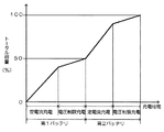
図2は、充電時間に対して、バッテリの残容量が増加する状態を示すグラフである。ただし、この図は、本発明の方法で2個のバッテリを充電する状態を示すのではなく、1個のバッテリを満充電した後、充電するバッテリを切り換えて、次のバッテリを満充電する状態を示している。このグラフに示すように、定電流充電と電圧制限充電は、単位時間にバッテリを充電できる容量が変化する。定電流充電は、バッテリ電圧に関係なく一定の電流で充電するので、単位時間の充電容量が大きい。電圧制限充電はバッテリ電圧が規定電圧を越えないように充電電流を制限するので、単位時間に対する充電容量が小さくなる。とくに、バッテリが満充電に近付くにしたがって、単位時間の充電容量が小さくなる。したがって、1個のバッテリを満充電する時間が2時間であれば、2個のバッテリを満充電するのに4時間かかる。また、完全に放電した2個のバッテリの充電を開始して、2時間経過した後には、1個のバッテリが満充電されるので、両方のバッテリを加算したトータル容量を100%とすれば、トータル容量の50%が充電されることになる。
【0028】
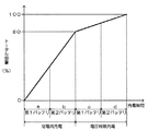
図3は、本発明の方法で2個のバッテリ1を充電する特性を示すグラフである。ただし、この図は、横軸を時間、縦軸をトータル容量としている。本発明の充電方法は、この図に示すように、最初に充電する第1バッテリ1Aの電圧が設定電圧よりも低いと、このバッテリ1の電圧が設定電圧になるまでは定電流充電する[領域a]。定電流充電しているバッテリ1の電圧が設定電圧になると、充電するバッテリ1を切り換えて、次に充電する第2バッテリ1Bをバッテリ電圧が設定電圧となるまで定電流充電する[領域b]。
【0029】
図3は2個のバッテリを充電する状態を示しているが、3個以上のバッテリを充電する場合は、定電流充電するバッテリを次々と切り換えて、全てのバッテリを設定電圧まで充電する。
【0030】
その後、バッテリ1の充電条件を定電流充電から電圧制限充電に切り換えて、満充電する。図3は、最初に第1バッテリ1Aを電圧制限充電して満充電し[領域c]、その後、第2バッテリ1Bを電圧制限充電して満充電して[領域d]、全てのバッテリ1を満充電している。図3は2個のバッテリを電圧制限充電して満充電する状態を示しているが、3個以上のバッテリを充電する方法にあっては、バッテリが満充電される毎に、充電するバッテリを切り換えて、全てのバッテリを順番に電圧制限充電して満充電する。さらに、図示しないが、電圧制限充電において、充電電流が減少する状態では、複数のバッテリ1を並列に接続して一緒に満充電することもできる。
【0031】
図3は、2個のバッテリ1のトータル容量が最初に急激に増加することを示している。すなわち、この図は、両方のバッテリ1を満充電する半分の時間で、両方のバッテリ1のトータル容量の80%も充電できることを示している。それは、図2において、第1バッテリ1Aを電圧制限充電する時間帯に、第2バッテリ1Bを定電流充電して能率よく充電できるからである。
【0032】
図4は、2個のバッテリ1の温度を検出しながら充電するバッテリA、Bを切り換えて充電する状態を示している。この図は、充電しているバッテリの温度が最高温度である45℃まで上昇すると、充電しているバッテリAからバッテリBに、またバッテリBからバッテリAに切り換える。温度が最高温度まで上昇していたバッテリは、充電が停止されて温度が次第に低下する。その後、充電するバッテリの温度が最高温度に上昇する毎に、充電するバッテリA、Bを切り換える。このようにして複数のバッテリを充電すると、バッテリの温度を最高温度よりも低くして、バッテリが高温になって性能が低下するのを防止できる。バッテリは、定電流充電している工程で温度が上昇しやすい。充電電流が大きいからである。このため、定電流充電する工程で、充電しているバッテリの温度が最高温度になると、充電するバッテリを切り換えて、バッテリの温度上昇を最高温度よりも低くできる。ただし、バッテリを電圧制限充電する工程において、バッテリの温度が最高温度になると、充電するバッテリを切り換えて、バッテリの温度障害による劣化は防止できる。
【0033】
さらに、図1の電源回路は、制御回路7で第1スイッチ2Aと第2スイッチ2Bを制御して、第1バッテリ1A、第2バッテリ1Bを1つずつ順番に放電して、負荷であるバッテリ使用機器9に電力を供給する。この状態でバッテリ使用機器9に電力を供給する放電バッテリ1の残容量が最低容量よりも少なくなり、あるいはバッテリ電圧が最低電圧よりも低くなると、残容量が最低容量よりも大きく、あるいはバッテリ電圧が最低電圧よりも高い別のバッテリ1から、バッテリ使用機器9に電力を供給しているバッテリ1に電力を供給して充電する。
【0034】
たとえば、第2スイッチ2Bをオフ、第1スイッチ2Aをオンとして第1バッテリ1Aを放電側バッテリとする状態で、第1バッテリ1Aの残容量が最低容量よりも小さくなり、あるいは第1バッテリ1Aの電圧が最低電圧よりも低くなると、制御回路7は第1スイッチ2Aと第2スイッチ2Bをオンにして、第2バッテリ1Bで第1バッテリ1Aを充電する。ただし、このとき、制御回路7は、第2バッテリ1Bの残容量が最低容量よりも大きいかどうか、あるいは第2バッテリ1Bの電圧が最低電圧よりも高いかどうかを検出して、残容量が最低容量よりも大きく、あるいはバッテリ電圧が最低電圧よりも高いときに限って、第1スイッチ2Aと第2スイッチ2Bをオンとして、第2バッテリ1Bで第1バッテリ1Aを充電する。第1スイッチ2Aと第2スイッチ2Bの両方がオンに切り換えられると、第1バッテリ1Aは第2バッテリ1Bよりも残容量が小さく、あるいは電圧が低いので、第2バッテリ1Bから第1バッテリ1Aに充電電流が流れて、第1バッテリ1Aが充電される。
【0035】
第2バッテリ1Bから第1バッテリ1Aに充電する充電容量は、第1バッテリ1Aから第2バッテリ1Bに切り換えできる容量、あるいは第1バッテリ1Aがバッテリ使用機器9の電源をオフにできる予め設定された最低使用容量とする。第2バッテリ1Bが、放電側バッテリである第1バッテリ1Aを最低使用容量充電すると、制御回路7は第2スイッチ2Bをオフにして、第1バッテリ1Aの充電を停止する。
【0036】
以上のようにして第1バッテリ1Aを最低使用容量まで充電する電源回路は、以下の状態で正常に使用される。
(1) 第1スイッチ2Aと第2スイッチ2Bがオンに切り換えられて、第1バッテリ1Aが最低使用容量まで充電される。
(2) この状態で、バッテリ使用機器9にACアダプターが接続されると、第1バッテリ1Aの充電が開始される。この状態で第2スイッチ2Bはオフの状態にあって、第2バッテリ1Bは充電されない。
(3) 第1バッテリ1Aが充分に充電されない状態で、ACアダプターが外されると、第1スイッチ2Aからバッテリ使用機器9に電力が供給される。このとき、第1バッテリ1Aの残容量が小さいと、第1バッテリ1Aから第2バッテリ1Bに切り換える前に、バッテリ使用機器9に電力を供給できなくなって、ラップトップマイコン等のバッテリ使用機器9はシャットダウンする。しかしながら、第1バッテリ1Aには第2バッテリ1Bから最低使用容量が充電されているので、第1バッテリ1Aは第2バッテリ1Bに切り換えられるまではバッテリ使用機器9に電力を供給する。このため、ラップトップマイコン等がシャットダウンすることなく、第1バッテリ1Aから第2バッテリ1Bに切り換えられる。
(4) その後、第2バッテリ1Bからバッテリ使用機器9に電力が供給される。
【0037】
【発明の効果】
本発明の請求項1と2に記載する複数のバッテリを充電する方法は、充電器の容量を大きくすることなく、限られた時間で充電できる容量を大きくできる特長がある。このため、短い時間充電して長い時間使用できる特長がある。それは、本発明の充電方法が、順番にバッテリを満充電するのではなく、バッテリ電圧が設定電圧となり、あるいは残容量が設定容量となるまでは、全てのバッテリを切り換えて定電流充電して大きな電流で効率よく充電するからである。
【0038】
また、本発明の請求項3の充電方法は、バッテリの温度上昇を小さくしながら連続してバッテリを充電でき、しかも高温環境における全てのバッテリの満充電時間を短縮しながら、温度障害を有効に防止できる特長がある。それは、バッテリの温度を検出して、バッテリの温度が最高温度になると充電するバッテリを切り換えて充電するからである。
【0039】
さらに、本発明の請求項5の充電方法は、複数のバッテリを順番に切り換えてひとつずつ充電すると共に、最初に充電するバッテリが満充電される前に充電しているバッテリの充電を停止して次のバッテリに切り換えて次のバッテリの充電を開始し、充電するバッテリを次々と切り換えて充電する。すなわち、ひとつのバッテリを満充電するまで連結して充電するのではなく、充電しているバッテリを切り換えながら充電するので、全てのバッテリを満充電する時間がない場合においても、すなわち、満充電する前の状態まで充電する場合においても、全てのバッテリを充電できるトータルの充電容量を大きくできる特徴がある。
【0040】
さらに、本発明の請求項6の複数のバッテリを放電する方法は、バッテリ使用機器に電力を供給しているバッテリの残容量が少なくなって、バッテリ使用機器がシャットダウンされる等して使用できなくなるのを有効に防止できる特長がある。それは、バッテリ使用機器に電力を供給する放電側バッテリの残容量が最低容量よりも少なくなり、あるいはバッテリ電圧が最低電圧よりも低くなると、残容量が最低容量よりも大きく、あるいはバッテリ電圧が最低電圧よりも高い別のバッテリから、バッテリ使用機器に電力を供給している放電側バッテリに電力を供給して充電するからである。
【図面の簡単な説明】
【図1】本発明の一実施例にかかる複数のバッテリを充放電する方法に使用する電源回路の回路図
【図2】1個のバッテリを満充電した後、次のバッテリを満充電するときの充電時間とバッテリ容量の関係を示すグラフ
【図3】本発明の一実施例にかかる充電方法で2個のバッテリを充電するときの充電時間とバッテリ容量の関係を示すグラフ
【図4】本発明の一実施例にかかる充電方法で2個のバッテリを充電するときのバッテリ温度の変化を示すグラフ
【符号の説明】
1…バッテリ
1A…第1バッテリ 1B…第2バッテリ
2…スイッチ
2A…第1スイッチ 2B…第2スイッチ
3…電圧検出回路
3A…第1電圧検出回路 3B…第2電圧検出回路
4…残容量検出回路
4A…第1残容量検出回路 4B…第2残容量検出回路
5A…第1温度センサー 5B…第2温度センサー
6…定電流・電圧制限充電回路
7…制御回路
8…出力端子
9…バッテリ使用機器[0001]
TECHNICAL FIELD OF THE INVENTION
The present invention relates to a method of charging a battery by switching a plurality of batteries in order, and supplying power to a device using the battery by switching a plurality of batteries in sequence.
[0002]
[Prior art]
A battery-equipped device in which a spare battery is mounted in addition to the main battery can be further used by switching to the spare battery after completely discharging the main battery. In order to extend the use time, battery-equipped devices equipped with a plurality of batteries have been developed (see Patent Document 1).
[0003]
[Patent Document 1]
JP-A-10-16869
[0004]
This publication describes a charge / discharge method in which a plurality of batteries are charged at the same time and switched and used in order. The method of charging the spare battery and the main battery simultaneously has a feature that both batteries can be fully charged in a short time. However, the charging current is twice as large as the charging current of one battery, and it is necessary to use a large-capacity charger, which makes the charger large and expensive. In order to solve such a drawback, there is a method of charging by switching a plurality of batteries in order.
[0005]
[Problems to be solved by the invention]
In this charging method, a plurality of batteries can be charged in order by a small-capacity charger for charging one battery. Therefore, the charger can be small and inexpensive. However, in this charging and discharging method, it takes time to fully charge all the batteries. This is because the charging time of all the batteries is the charging time of one battery × the number of batteries.
[0006]
In some cases, the battery may be used while charging is limited and charging is interrupted during charging. That is, there is no time to fully charge all the batteries, and charging may be interrupted and used before the batteries are fully charged. In this case, it is important that the battery can be used as long as possible with a short charging time. For example, if the charging time is limited to half of the time to fully charge all batteries, if it can be charged to exceed 50% of the charging capacity of all batteries, charge for a short limited time and then a longer time There are features that can be used.
[0007]
The first object of the present invention has been developed to achieve this. An important object of the present invention is to provide a method of charging a plurality of batteries that can increase the charging capacity in a limited time without increasing the capacity of the charger.
[0008]
Also, when the battery is charged in a high temperature environment, the temperature of the battery itself may become abnormally high. This is because heat is generated inside the battery when charged. If the temperature of the battery becomes abnormally high, the battery performance deteriorates. Therefore, when the battery temperature becomes abnormally high, it is necessary to interrupt charging and cool the battery. Since charging cannot be performed when the battery is cooled, there is a disadvantage that the total charging time is prolonged in this state.
[0009]
A second object of the present invention is to overcome this drawback. That is, a second object of the present invention is to continuously charge the battery while reducing the temperature rise of the battery, and to effectively prevent the temperature failure while shortening the full charge time of all the batteries in a high temperature environment. An object of the present invention is to provide a method for charging a plurality of batteries.
[0010]
Furthermore, battery-powered devices such as laptop microcomputers having a plurality of batteries mounted thereon are switched over and used continuously when the remaining capacity of the battery being used becomes small. However, the used battery may not be able to discharge before switching is completed. In this state, the laptop microcomputer or the like shuts down during switching, and cannot be used continuously.
[0011]
This state occurs, for example, when the apparatus is used in the following state.
The laptop microcomputer has a first battery and a second battery. The remaining capacity of the first battery is 0%, and the remaining capacity of the second battery is 80%. It is assumed that an AC adapter is connected to the laptop microcomputer, the AC adapter is charging the first battery, and power is being supplied to the laptop microcomputer from the charged first battery. It is assumed that the AC adapter is disconnected before the first battery is sufficiently charged, that is, in a state where the remaining capacity of the first battery is almost 0%. Since the remaining capacity of the first battery is small, the laptop microcomputer attempts to switch the power source from the first battery to the second battery. However, since the first battery has almost no remaining capacity, the laptop microcomputer cannot be driven, and the laptop microcomputer shuts down before switching the battery. At this time, even if the second battery has remaining capacity and the laptop microcomputer can be driven, the laptop microcomputer shuts down before switching.
[0012]
A third object of the present invention is to solve this drawback, that is, to discharge a plurality of batteries while effectively preventing the remaining capacity of any one of the batteries from decreasing so that the battery-powered equipment cannot be used. It is to provide a method that can be performed.
[0013]
[Means for Solving the Problems]
A method of charging a plurality of batteries according to claim 1 of the present invention is a charging method including a step of sequentially switching a plurality of batteries to charge one by one, wherein the battery is kept at a constant current until the battery voltage reaches a set voltage. After that, the battery is charged with the voltage limited while regulating the battery voltage. In this charging method, when the voltage of the battery to be charged first is lower than the set voltage, the battery is charged at a constant current until the voltage reaches the set voltage, and when the voltage of the battery being charged at the constant current reaches the set voltage, the battery to be charged is switched. Then, the next battery is charged at a constant current until the battery voltage reaches the set voltage, the batteries to be charged at the constant current are switched one after another, and all the batteries are charged to the set voltage. Thereafter, the charging condition of the battery is switched from constant current charging to voltage limited charging, and the battery is fully charged.
[0014]
A method of charging a plurality of batteries according to claim 2 of the present invention is a charging method including a step of switching a plurality of batteries in order and charging each one by one, wherein the batteries are charged until the remaining capacity of the battery reaches a set capacity. The battery is charged at a constant current, and thereafter, voltage-limited charging is performed while regulating the battery voltage. In this charging method, if the remaining capacity of the battery to be charged first is smaller than the set capacity, constant-current charging is performed until the remaining capacity reaches the set capacity, and charging is performed when the remaining capacity of the constant-current charged battery reaches the set capacity. The batteries are switched, and the next battery is charged at a constant current until the remaining capacity reaches the set capacity. The batteries to be charged at the constant current are switched one after another, and all the batteries are charged to the set capacity. Thereafter, the charging condition of the battery is switched from constant current charging to voltage limited charging, and the battery is fully charged.
[0015]
Further, in the charging method according to the third aspect of the present invention, the battery temperature is detected, and the battery to be charged is switched when the battery temperature reaches the maximum temperature. Furthermore, in the charging method according to a fourth aspect of the present invention, the battery to be charged is a lithium ion battery.
[0016]
The charging method according to claim 5 of the present invention is a charging method including a step of sequentially switching a plurality of batteries to charge one by one, wherein the charging of the battery is performed before the battery to be charged first is fully charged. By stopping and switching to the next battery and starting charging the next battery, the batteries to be charged are switched one after another, and all the batteries are charged to a state before they are fully charged.
[0017]
In the method for discharging a plurality of batteries according to a sixth aspect of the present invention, the plurality of batteries are sequentially discharged one by one to supply power to a battery-powered device. When the remaining capacity of the discharging battery that supplies power to the battery-powered device becomes smaller than the minimum capacity, or when the battery voltage becomes lower than the minimum voltage, the remaining capacity becomes larger than the minimum capacity, or the battery voltage becomes lower. Supplies power from another battery having a voltage higher than the minimum voltage to a discharging battery that supplies power to the battery-powered equipment, and charges the discharging battery.
[0018]
BEST MODE FOR CARRYING OUT THE INVENTION
Hereinafter, embodiments of the present invention will be described with reference to the drawings. However, the following examples illustrate a method for charging and discharging a plurality of batteries for embodying the technical idea of the present invention, and the present invention describes a method for charging and discharging a battery. Not specified below.
[0019]
FIG. 1 shows a power supply circuit that switches and charges and discharges a plurality of first batteries 1A and second batteries 1B. The power supply circuit includes a constant current / voltage limiting charging circuit 6 for charging the battery 1 with a constant current and for limiting the voltage, two first batteries 1A and a second battery 1B, and each of the batteries 1 is connected to an
[0020]
In the power supply circuit shown in the figure, the control circuit 7 controls the
[0021]
Further, in the power supply circuit shown in the figure, the control circuit 7 controls the constant-current / voltage-limited charging circuit 6 to charge the battery 1 with a constant current or with a voltage-limited charge. The control circuit 7 controls the constant current / voltage limited charging circuit 6 based on the battery voltage or the remaining capacity of the battery 1 to switch the state of charging the battery 1 between constant current charging and voltage limited charging. The battery voltage is input from the
[0022]
The power supply circuit shown in FIG. 1 is suitable for using the battery 1 as a lithium ion battery. However, the battery may be a secondary battery other than the lithium ion battery, for example, a nickel-hydrogen battery or a nickel-cadmium battery. Lithium-ion batteries are charged at a constant current until the battery voltage rises to the set voltage in order to fully charge while preventing battery performance from deteriorating, and when the battery voltage reaches the set voltage, voltage-limited charging is performed while regulating the battery voltage Is done. This method allows a full charge without deteriorating the performance of the lithium ion battery. However, a nickel-hydrogen battery or a nickel-cadmium battery can be fully charged by this method, and can be fully charged while minimizing deterioration of battery performance.
[0023]
The control circuit 7 controls the constant-current / voltage-limited charging circuit 6 to terminate the constant-current charging, and the set voltage is set to a voltage optimal for the type of the battery 1. This set voltage is set to a voltage at which the performance of the battery 1 does not decrease while the battery 1 is rapidly charged in a short time. For example, in the case of a lithium ion battery, the set voltage is set to 4.1 to 4.3V. In the case of a nickel-hydrogen battery or a nickel-cadmium battery, the voltage is set to 1.5 to 2.0V. The set voltage is stored in a storage circuit (not shown) of the control circuit 7.
[0024]
Switching from constant-current charging to voltage-limited charging can be performed by detecting the remaining capacity of the battery 1 instead of the battery voltage. In this method, the remaining capacity of the battery 1 being charged is detected by the remaining
[0025]
According to the charging method of the present invention, instead of charging a plurality of batteries 1 at the same time, the batteries 1 to be charged are switched in order and charged at a constant current one by one. The battery 1 is charged at a constant current until the voltage reaches the set voltage or the remaining capacity reaches the set capacity, and thereafter the battery 1 is fully charged by voltage-limited charging. In the constant current charging, since the charging current is large, the charging is performed one by one. In the voltage-limited charging, the charging current gradually decreases. Therefore, when the charging current decreases, the plurality of batteries 1 can be charged together. When charging the plurality of batteries 1 together, the control circuit 7 turns on the
[0026]
The constant current / voltage limited charging circuit 6 charges the battery 1 while maintaining a constant charging current in constant current charging. In the voltage-limited charging, the battery 1 is charged by constant-voltage charging. In the constant voltage charging, the battery 1 is fully charged by controlling the charging current so that the battery voltage does not exceed the regulation voltage. However, the present invention does not specify voltage-limited charging as constant-voltage charging. The constant current / voltage limited charging circuit 6 detects the battery voltage by the
[0027]
FIG. 2 is a graph showing a state in which the remaining capacity of the battery increases with respect to the charging time. However, this figure does not show a state in which two batteries are charged by the method of the present invention, but a state in which one battery is fully charged, the battery to be charged is switched, and the next battery is fully charged. Is shown. As shown in this graph, in the constant current charging and the voltage limited charging, the capacity that can charge the battery per unit time changes. In the constant current charging, the charging is performed with a constant current regardless of the battery voltage, so that the charging capacity per unit time is large. In the voltage-limited charging, the charging current is limited so that the battery voltage does not exceed the specified voltage, so that the charging capacity per unit time decreases. In particular, the charge capacity per unit time decreases as the battery approaches full charge. Therefore, if the time to fully charge one battery is two hours, it takes four hours to fully charge two batteries. In addition, one battery is fully charged after two hours from the start of charging of the two completely discharged batteries. Therefore, if the total capacity of both batteries is set to 100%, 50% of the total capacity will be charged.
[0028]
FIG. 3 is a graph showing characteristics of charging two batteries 1 by the method of the present invention. In this figure, the horizontal axis represents time, and the vertical axis represents total capacity. According to the charging method of the present invention, when the voltage of the first battery 1A to be charged first is lower than the set voltage, constant current charging is performed until the voltage of the battery 1 reaches the set voltage, as shown in FIG. a]. When the voltage of the battery 1 being charged at a constant current reaches the set voltage, the battery 1 to be charged is switched, and the second battery 1B to be charged next is charged at a constant current until the battery voltage reaches the set voltage [region b].
[0029]
FIG. 3 shows a state in which two batteries are charged. However, when charging three or more batteries, the batteries to be charged at a constant current are switched one after another, and all the batteries are charged to a set voltage.
[0030]
Thereafter, the charging condition of the battery 1 is switched from constant current charging to voltage limited charging, and the battery 1 is fully charged. FIG. 3 shows that the first battery 1A is first fully charged by voltage-limited charging [region c], and then the second battery 1B is fully charged by voltage-limited charging [region d], and all the batteries 1 are charged. Fully charged. FIG. 3 shows a state in which two batteries are fully charged by voltage-limited charging. However, in the method of charging three or more batteries, the battery to be charged is charged every time the batteries are fully charged. By switching, all the batteries are charged in a voltage-limited manner in order and fully charged. Further, although not shown, in the voltage-limited charging, when the charging current is reduced, a plurality of batteries 1 can be connected in parallel and fully charged together.
[0031]
FIG. 3 shows that the total capacity of the two batteries 1 suddenly increases at first. That is, this figure shows that 80% of the total capacity of both batteries 1 can be charged in half the time when both batteries 1 are fully charged. This is because, in FIG. 2, the second battery 1B can be charged at a constant current and can be efficiently charged in the time period in which the first battery 1A is voltage-limited charged.
[0032]
FIG. 4 shows a state in which the batteries A and B that are charged while detecting the temperatures of the two batteries 1 are switched and charged. In this figure, when the temperature of the battery being charged rises to the maximum temperature of 45 ° C., switching is made from the battery A being charged to the battery B and from the battery B to the battery A. The battery whose temperature has risen to the maximum temperature is stopped charging and the temperature gradually decreases. Thereafter, each time the temperature of the battery to be charged rises to the maximum temperature, the batteries A and B to be charged are switched. When a plurality of batteries are charged in this manner, the temperature of the batteries can be made lower than the maximum temperature to prevent the batteries from becoming hot and deteriorating in performance. The temperature of the battery tends to rise during the process of constant current charging. This is because the charging current is large. For this reason, when the temperature of the battery being charged reaches the maximum temperature in the step of performing constant-current charging, the battery to be charged is switched, and the temperature rise of the battery can be made lower than the maximum temperature. However, when the temperature of the battery reaches the maximum temperature in the step of charging the battery with voltage limitation, the battery to be charged is switched to prevent the deterioration due to the temperature failure of the battery.
[0033]
Further, in the power supply circuit of FIG. 1, the control circuit 7 controls the
[0034]
For example, in a state where the second switch 2B is turned off and the
[0035]
The charging capacity for charging the first battery 1A from the second battery 1B is a capacity that can be switched from the first battery 1A to the second battery 1B or a preset capacity that allows the first battery 1A to turn off the power of the battery-using device 9. The minimum used capacity. When the second battery 1B charges the first battery 1A, which is a discharging battery, to the minimum use capacity, the control circuit 7 turns off the second switch 2B to stop charging the first battery 1A.
[0036]
The power supply circuit that charges the first battery 1A to the minimum use capacity as described above is normally used in the following state.
(1) The
(2) In this state, when the AC adapter is connected to the battery using device 9, charging of the first battery 1A is started. In this state, the second switch 2B is off, and the second battery 1B is not charged.
(3) When the AC adapter is disconnected while the first battery 1A is not sufficiently charged, power is supplied from the
(4) Thereafter, power is supplied from the second battery 1B to the battery-powered device 9.
[0037]
【The invention's effect】
The method for charging a plurality of batteries according to claims 1 and 2 of the present invention has a feature that the capacity that can be charged in a limited time can be increased without increasing the capacity of the charger. Therefore, there is a feature that the battery can be charged for a short time and used for a long time. The reason is that the charging method of the present invention does not sequentially charge the batteries fully, but switches all the batteries and performs constant current charging until the battery voltage reaches the set voltage or the remaining capacity reaches the set capacity. This is because the battery is charged efficiently by the current.
[0038]
Further, the charging method according to the third aspect of the present invention can continuously charge the battery while minimizing the temperature rise of the battery, and effectively reduce the temperature failure while reducing the full charge time of all the batteries in a high temperature environment. There is a feature that can be prevented. This is because the battery temperature is detected, and when the battery temperature reaches the maximum temperature, the battery to be charged is switched and charged.
[0039]
Further, in the charging method according to the fifth aspect of the present invention, the plurality of batteries are switched in order and charged one by one, and the charging of the charged battery is stopped before the first charged battery is fully charged. The next battery is switched to start charging the next battery, and the batteries to be charged are switched one after another for charging. That is, instead of connecting and charging one battery until it is fully charged, charging is performed while switching the charging battery, so even when there is no time to fully charge all the batteries, that is, the battery is fully charged. Even when the battery is charged up to the previous state, there is a feature that the total charge capacity capable of charging all the batteries can be increased.
[0040]
Further, in the method for discharging a plurality of batteries according to claim 6 of the present invention, the remaining capacity of the battery that supplies power to the battery-powered device decreases, and the battery-powered device becomes unusable, for example, shut down. There is a feature that can be effectively prevented. When the remaining capacity of the discharging battery that supplies power to the battery-powered device becomes smaller than the minimum capacity, or when the battery voltage becomes lower than the minimum voltage, the remaining capacity becomes larger than the minimum capacity, or when the battery voltage becomes lower than the minimum voltage. This is because power is supplied from another higher battery to a discharge-side battery that supplies power to the battery-powered device and is charged.
[Brief description of the drawings]
FIG. 1 is a circuit diagram of a power supply circuit used in a method for charging and discharging a plurality of batteries according to an embodiment of the present invention.
FIG. 2 is a graph showing a relationship between charging time and battery capacity when one battery is fully charged and then the next battery is fully charged.
FIG. 3 is a graph showing a relationship between charging time and battery capacity when two batteries are charged by the charging method according to one embodiment of the present invention.
FIG. 4 is a graph showing a change in battery temperature when two batteries are charged by the charging method according to one embodiment of the present invention;
[Explanation of symbols]
1 ... Battery
1A: first battery 1B: second battery
2 ... Switch
2A: First switch 2B: Second switch
3: Voltage detection circuit
3A: first
4: Remaining capacity detection circuit
4A: first remaining
5A: First temperature sensor 5B: Second temperature sensor
6. Constant current / voltage limited charging circuit
7 ... Control circuit
8 Output terminal
9 Battery-powered equipment
Claims (6)
最初に充電するバッテリの電圧が設定電圧よりも低いと設定電圧になるまでは定電流充電し、定電流充電しているバッテリの電圧が設定電圧になると、充電するバッテリを切り換えて、次のバッテリをバッテリ電圧が設定電圧となるまで定電流充電し、定電流充電するバッテリを次々と切り換えて、全てのバッテリを設定電圧まで充電し、
その後、バッテリの充電条件を定電流充電から電圧制限充電に切り換えて、満充電することを特徴とする複数のバッテリを充電する方法。A charging method including a step of sequentially switching a plurality of batteries to charge one battery at a time, wherein the battery is charged at a constant current until the battery voltage reaches a set voltage, and thereafter, the battery is charged by voltage limiting while regulating the battery voltage. A method of charging a battery of
If the voltage of the battery to be charged first is lower than the set voltage, the battery is charged at a constant current until the voltage reaches the set voltage. Is charged at a constant current until the battery voltage reaches the set voltage, the batteries to be charged at a constant current are switched one after another, and all the batteries are charged to the set voltage.
A method of charging a plurality of batteries, wherein the battery is fully charged by switching a charging condition of the battery from constant current charging to voltage limited charging.
最初に充電するバッテリの残容量が設定容量よりも小さいと、設定容量になるまでは定電流充電し、定電流充電しているバッテリの残容量が設定容量になると、充電するバッテリを切り換えて、次のバッテリを残容量が設定容量となるまで定電流充電し、定電流充電するバッテリを次々と切り換えて、全てのバッテリを設定容量まで充電し、
その後、バッテリの充電条件を定電流充電から電圧制限充電に切り換えて、満充電することを特徴とする複数のバッテリを充電する方法。A charging method including a step of charging a battery by switching a plurality of batteries in order, wherein the battery is charged at a constant current until the remaining capacity of the battery reaches a set capacity, and then voltage-limited charging while regulating the battery voltage. A method of charging a plurality of batteries,
If the remaining capacity of the battery to be charged first is smaller than the set capacity, constant-current charging is performed until the remaining capacity reaches the set capacity. The next battery is charged with constant current until the remaining capacity reaches the set capacity, the batteries to be charged with constant current are switched one after another, and all batteries are charged to the set capacity,
A method of charging a plurality of batteries, wherein the battery is fully charged by switching a charging condition of the battery from constant current charging to voltage limited charging.
最初に充電するバッテリが満充電される前に当該バッテリの充電を停止して次のバッテリに切り換えて次のバッテリの充電を開始することにより、充電するバッテリを次々と切り換えて、全てのバッテリを満充電する前の状態に充電することを特徴とする複数のバッテリを充電する方法。A charging method including a step of switching a plurality of batteries in order and charging one by one,
Before the first battery to be charged is fully charged, the charging of the battery is stopped, the next battery is switched to the next battery, and the charging of the next battery is started. A method for charging a plurality of batteries, wherein the battery is charged to a state before being fully charged.
バッテリ使用機器に電力を供給する放電側バッテリの残容量が最低容量よりも少なくなり、あるいはバッテリ電圧が最低電圧よりも低くなると、残容量が最低容量よりも大きく、あるいはバッテリ電圧が最低電圧よりも高い別のバッテリから、バッテリ使用機器に電力を供給している放電側バッテリに電力を供給して充電することを特徴とする複数のバッテリを放電する方法。A method of discharging a plurality of batteries that sequentially discharges a plurality of batteries one by one to supply power to a battery-using device,
If the remaining capacity of the discharging battery that supplies power to the battery-powered device becomes less than the minimum capacity, or if the battery voltage becomes lower than the minimum voltage, the remaining capacity becomes larger than the minimum capacity, or the battery voltage becomes higher than the minimum voltage. A method for discharging a plurality of batteries, comprising: supplying power from another high battery to a discharging battery that supplies power to a battery-using device, and charging the discharging battery.
Priority Applications (4)
| Application Number | Priority Date | Filing Date | Title |
|---|---|---|---|
| JP2003155708A JP2004357481A (en) | 2003-05-30 | 2003-05-30 | Method of charging a plurality of batteries, and method of discharging |
| TW093106008A TW200427124A (en) | 2003-05-30 | 2004-03-08 | Methods for charging and discharging a plurality of batteries |
| US10/854,366 US20050001593A1 (en) | 2003-05-30 | 2004-05-27 | Method of charging and discharging a plurality of batteries |
| CNA2004100473251A CN1574447A (en) | 2003-05-30 | 2004-05-31 | Method of charging and discharging a plurality of batteries |
Applications Claiming Priority (1)
| Application Number | Priority Date | Filing Date | Title |
|---|---|---|---|
| JP2003155708A JP2004357481A (en) | 2003-05-30 | 2003-05-30 | Method of charging a plurality of batteries, and method of discharging |
Publications (1)
| Publication Number | Publication Date |
|---|---|
| JP2004357481A true JP2004357481A (en) | 2004-12-16 |
Family
ID=33549154
Family Applications (1)
| Application Number | Title | Priority Date | Filing Date |
|---|---|---|---|
| JP2003155708A Pending JP2004357481A (en) | 2003-05-30 | 2003-05-30 | Method of charging a plurality of batteries, and method of discharging |
Country Status (4)
| Country | Link |
|---|---|
| US (1) | US20050001593A1 (en) |
| JP (1) | JP2004357481A (en) |
| CN (1) | CN1574447A (en) |
| TW (1) | TW200427124A (en) |
Cited By (9)
| Publication number | Priority date | Publication date | Assignee | Title |
|---|---|---|---|---|
| JP2009027789A (en) * | 2007-07-18 | 2009-02-05 | Nippon Telegr & Teleph Corp <Ntt> | Battery system |
| JP2011002991A (en) * | 2009-06-18 | 2011-01-06 | Nissan Motor Co Ltd | Power supply device |
| JP2012110221A (en) * | 2005-12-16 | 2012-06-07 | Hitachi Vehicle Energy Ltd | Storage battery management device |
| CN102742067A (en) * | 2009-08-17 | 2012-10-17 | 苹果公司 | Increasing energy density in rechargeable lithium battery cells |
| JP2014078358A (en) * | 2012-10-09 | 2014-05-01 | Mitsubishi Motors Corp | Power control device |
| JP2015092479A (en) * | 2013-11-06 | 2015-05-14 | ザ・ボーイング・カンパニーTheBoeing Company | Virtual cell for battery thermal management |
| JP2015515854A (en) * | 2012-04-27 | 2015-05-28 | スコット クラーク, エル.ピー. | Power supply system for moving cart and operation method of power supply system |
| JP2016067104A (en) * | 2014-09-24 | 2016-04-28 | レノボ・シンガポール・プライベート・リミテッド | Portable information processing unit, battery control method thereof, and computer executable program |
| JP7504613B2 (en) | 2020-02-14 | 2024-06-24 | 新コスモス電機株式会社 | Charging Systems and Chargers |
Families Citing this family (36)
| Publication number | Priority date | Publication date | Assignee | Title |
|---|---|---|---|---|
| JP4843921B2 (en) * | 2004-09-02 | 2011-12-21 | 日産自動車株式会社 | Battery pack capacity adjustment device and battery pack capacity adjustment method |
| US20070063675A1 (en) * | 2005-09-19 | 2007-03-22 | Walline Erin K | Method and system for providing battery usable life information to users of information handling systems |
| JP2007236027A (en) * | 2006-02-27 | 2007-09-13 | Matsushita Electric Works Ltd | Charging equipment |
| US7518338B2 (en) | 2006-04-13 | 2009-04-14 | Dell Products L.P. | Parallel hybrid battery pack charging |
| KR100824905B1 (en) * | 2006-08-24 | 2008-04-23 | 삼성에스디아이 주식회사 | Hybrid battery and full charge capacity calculation method thereof |
| FR2924870B1 (en) * | 2007-12-10 | 2010-01-08 | Valeo Equip Electr Moteur | ENERGY STORAGE DEVICE, IN PARTICULAR FOR MOTOR VEHICLE. |
| CN101291079B (en) * | 2007-04-18 | 2010-10-13 | 深圳市盈基实业有限公司 | Adaptive battery charging circuit |
| CN101436650B (en) * | 2007-11-16 | 2011-12-28 | 联想(北京)有限公司 | Battery box and charging/discharging control method thereof, notebook-type computer |
| CN101488591B (en) * | 2008-01-16 | 2011-12-07 | 仁宝电脑工业股份有限公司 | Method for multi-section charging cell module |
| US20090212635A1 (en) * | 2008-02-21 | 2009-08-27 | Mv Circuit Design Inc. | Charge coupling and decoupling circuit |
| CN102077440A (en) * | 2008-07-03 | 2011-05-25 | 日立工机株式会社 | Charging system and battery pack |
| WO2011014595A2 (en) | 2009-07-31 | 2011-02-03 | Thermo King Corporation | Bi-directional battery voltage converter |
| US9007025B2 (en) | 2010-04-07 | 2015-04-14 | Dell Products, L.P. | Systems and methods for configuring and charging hybrid battery systems |
| JP5637878B2 (en) * | 2011-01-27 | 2014-12-10 | 株式会社日立製作所 | Secondary battery system |
| WO2012178211A2 (en) * | 2011-06-24 | 2012-12-27 | L.R.S. Innovations, Inc. | Electric vehicle |
| US9077053B2 (en) | 2011-07-20 | 2015-07-07 | Milwaukee Electric Tool Corporation | Battery charger including multiple charging ports on surfaces forming an apex |
| WO2011137869A2 (en) * | 2011-07-21 | 2011-11-10 | 华为终端有限公司 | Wireless wideband device |
| JP5662900B2 (en) * | 2011-08-08 | 2015-02-04 | 日立建機株式会社 | Electric construction machine |
| DK2815483T3 (en) | 2012-02-17 | 2022-02-28 | Milwaukee Electric Tool Corp | MULTIROOM DATAR CHARGER |
| DE102012205260A1 (en) * | 2012-03-30 | 2013-10-02 | Robert Bosch Gmbh | Electrical device and method for operating an electrical device |
| CN102623768B (en) * | 2012-03-30 | 2014-08-27 | 青岛海信移动通信技术股份有限公司 | Multi-battery charging method and device and handheld mobile terminal |
| DE102012207674A1 (en) * | 2012-05-09 | 2013-11-14 | Robert Bosch Gmbh | Method and device for adjusting the states of charge of a battery |
| US9368991B2 (en) | 2012-10-30 | 2016-06-14 | The Board Of Trustees Of The University Of Alabama | Distributed battery power electronics architecture and control |
| US9236763B2 (en) | 2012-11-12 | 2016-01-12 | Dresser, Inc. | Device and method for distributing power at a remote pumping system |
| US9356458B2 (en) * | 2012-12-04 | 2016-05-31 | Paul M. Nevins | Switch-controlled energy cycling apparatus |
| JP6439146B2 (en) * | 2014-01-29 | 2018-12-19 | パナソニックIpマネジメント株式会社 | Power supply |
| KR102234703B1 (en) * | 2014-03-04 | 2021-04-01 | 삼성에스디아이 주식회사 | Energy storage system and method for controlling thereof |
| US9760520B2 (en) | 2014-07-11 | 2017-09-12 | Covidien Lp | Dynamic system management bus for an electrosurgical system |
| JP2017525323A (en) * | 2015-06-30 | 2017-08-31 | エスゼット ディージェイアイ テクノロジー カンパニー リミテッドSz Dji Technology Co.,Ltd | Charging control circuit, charging device, charging system and charging control method |
| CN107104249B (en) * | 2016-02-23 | 2019-08-30 | 东莞新能源科技有限公司 | Method of charging lithium-ion battery |
| TWI633738B (en) * | 2016-09-07 | 2018-08-21 | 華碩電腦股份有限公司 | Charging-discharging module of the energy storage unit and charging-discharging method thereof |
| JP6596458B2 (en) * | 2017-03-13 | 2019-10-23 | 株式会社日立建機ティエラ | Hydraulic drive device for electric hydraulic work machine |
| WO2018222261A1 (en) * | 2017-06-01 | 2018-12-06 | Florida Atlantic University Board Of Trustees | Systems and methods for federated power management |
| CN109148985A (en) | 2017-06-15 | 2019-01-04 | 苏州宝时得电动工具有限公司 | A kind of battery pack charging method and device |
| KR20200101754A (en) * | 2019-02-20 | 2020-08-28 | 삼성에스디아이 주식회사 | Battery control appratus and battery control method |
| US20200395774A1 (en) * | 2019-06-17 | 2020-12-17 | Renesas Electronics America Inc. | Single inductor multiple output charger for multiple battery applications |
Family Cites Families (4)
| Publication number | Priority date | Publication date | Assignee | Title |
|---|---|---|---|---|
| JPH07212980A (en) * | 1994-01-13 | 1995-08-11 | Fujitsu Ltd | Battery charging and discharging device |
| JPH0997629A (en) * | 1995-09-29 | 1997-04-08 | Sanyo Electric Co Ltd | Plural lithium ion secondary battery charging method |
| US6198251B1 (en) * | 1997-06-03 | 2001-03-06 | Fluor Corporation | Method for sequentially charging batteries in situ |
| US6518725B2 (en) * | 2000-01-28 | 2003-02-11 | Semtech Corporation | Charge balancing system |
-
2003
- 2003-05-30 JP JP2003155708A patent/JP2004357481A/en active Pending
-
2004
- 2004-03-08 TW TW093106008A patent/TW200427124A/en unknown
- 2004-05-27 US US10/854,366 patent/US20050001593A1/en not_active Abandoned
- 2004-05-31 CN CNA2004100473251A patent/CN1574447A/en active Pending
Cited By (14)
| Publication number | Priority date | Publication date | Assignee | Title |
|---|---|---|---|---|
| JP2012110221A (en) * | 2005-12-16 | 2012-06-07 | Hitachi Vehicle Energy Ltd | Storage battery management device |
| JP2009027789A (en) * | 2007-07-18 | 2009-02-05 | Nippon Telegr & Teleph Corp <Ntt> | Battery system |
| JP2009261246A (en) * | 2007-07-18 | 2009-11-05 | Nippon Telegr & Teleph Corp <Ntt> | Battery system |
| JP4612099B2 (en) * | 2007-07-18 | 2011-01-12 | 日本電信電話株式会社 | Battery system |
| JP4612022B2 (en) * | 2007-07-18 | 2011-01-12 | 日本電信電話株式会社 | Battery system |
| JP2011002991A (en) * | 2009-06-18 | 2011-01-06 | Nissan Motor Co Ltd | Power supply device |
| CN102742067A (en) * | 2009-08-17 | 2012-10-17 | 苹果公司 | Increasing energy density in rechargeable lithium battery cells |
| JP2015515854A (en) * | 2012-04-27 | 2015-05-28 | スコット クラーク, エル.ピー. | Power supply system for moving cart and operation method of power supply system |
| JP2014078358A (en) * | 2012-10-09 | 2014-05-01 | Mitsubishi Motors Corp | Power control device |
| JP2015092479A (en) * | 2013-11-06 | 2015-05-14 | ザ・ボーイング・カンパニーTheBoeing Company | Virtual cell for battery thermal management |
| KR20150053226A (en) * | 2013-11-06 | 2015-05-15 | 더 보잉 컴파니 | Virtual Cell for Battery Thermal Management |
| KR102205684B1 (en) * | 2013-11-06 | 2021-01-21 | 더 보잉 컴파니 | Virtual Cell for Battery Thermal Management |
| JP2016067104A (en) * | 2014-09-24 | 2016-04-28 | レノボ・シンガポール・プライベート・リミテッド | Portable information processing unit, battery control method thereof, and computer executable program |
| JP7504613B2 (en) | 2020-02-14 | 2024-06-24 | 新コスモス電機株式会社 | Charging Systems and Chargers |
Also Published As
| Publication number | Publication date |
|---|---|
| CN1574447A (en) | 2005-02-02 |
| US20050001593A1 (en) | 2005-01-06 |
| TW200427124A (en) | 2004-12-01 |
Similar Documents
| Publication | Publication Date | Title |
|---|---|---|
| JP2004357481A (en) | Method of charging a plurality of batteries, and method of discharging | |
| TWI594540B (en) | Power storage system and power source system | |
| JP4660523B2 (en) | Charging system that controls charging at the surface temperature of the battery cell | |
| TWI445277B (en) | A charging system, a charging method, and an information processing device | |
| JP5230563B2 (en) | Battery management system with controllable adapter output | |
| US11522381B2 (en) | Charging device and charging method | |
| US7772807B2 (en) | Method for charging portable electronic device | |
| US8344700B2 (en) | Charging method and charger | |
| JP4967162B2 (en) | Secondary battery pack | |
| JP5506498B2 (en) | Secondary battery charging device and charging method | |
| CN103636097A (en) | Charging of li-ion batteries | |
| US20130057218A1 (en) | Device and method for controlling charge of assembled battery | |
| WO2015079607A1 (en) | Battery pack | |
| JP2009225632A (en) | Charging control circuit, battery pack, and charging system | |
| JP2011082158A (en) | Charge control method of battery pack | |
| JP6824295B2 (en) | Electrical equipment | |
| JP2005151683A (en) | Battery pack charger | |
| US20100231177A1 (en) | Battery pack and charger system | |
| JPH097641A (en) | Charging method of secondary battery | |
| JP2006203978A (en) | Uninterruptible power system | |
| US20050052159A1 (en) | Method and apparatus for overcharge protection using analog overvoltage detection | |
| JP2011182479A (en) | System and method for charging lithium ion battery pack | |
| JP5350734B2 (en) | Secondary battery discharge circuit, secondary battery discharge method and information processing apparatus | |
| JP2001169471A (en) | Secondary cell device | |
| WO2012049973A1 (en) | Power management system |
Legal Events
| Date | Code | Title | Description |
|---|---|---|---|
| A621 | Written request for application examination |
Free format text: JAPANESE INTERMEDIATE CODE: A621 Effective date: 20060127 |
|
| A977 | Report on retrieval |
Free format text: JAPANESE INTERMEDIATE CODE: A971007 Effective date: 20070122 |
|
| A131 | Notification of reasons for refusal |
Free format text: JAPANESE INTERMEDIATE CODE: A131 Effective date: 20070130 |
|
| A02 | Decision of refusal |
Free format text: JAPANESE INTERMEDIATE CODE: A02 Effective date: 20070605 |