JP2017525323A - Charging control circuit, charging device, charging system and charging control method - Google Patents
Charging control circuit, charging device, charging system and charging control method Download PDFInfo
- Publication number
- JP2017525323A JP2017525323A JP2016546089A JP2016546089A JP2017525323A JP 2017525323 A JP2017525323 A JP 2017525323A JP 2016546089 A JP2016546089 A JP 2016546089A JP 2016546089 A JP2016546089 A JP 2016546089A JP 2017525323 A JP2017525323 A JP 2017525323A
- Authority
- JP
- Japan
- Prior art keywords
- charging
- unit
- control unit
- voltage
- battery
- Prior art date
- Legal status (The legal status is an assumption and is not a legal conclusion. Google has not performed a legal analysis and makes no representation as to the accuracy of the status listed.)
- Pending
Links
Images


Classifications
-
- H—ELECTRICITY
- H02—GENERATION; CONVERSION OR DISTRIBUTION OF ELECTRIC POWER
- H02J—CIRCUIT ARRANGEMENTS OR SYSTEMS FOR SUPPLYING OR DISTRIBUTING ELECTRIC POWER; SYSTEMS FOR STORING ELECTRIC ENERGY
- H02J7/00—Circuit arrangements for charging or depolarising batteries or for supplying loads from batteries
- H02J7/0013—Circuit arrangements for charging or depolarising batteries or for supplying loads from batteries acting upon several batteries simultaneously or sequentially
Abstract
本発明は、充電制御回路であって、充電ユニットと、複数であり、それぞれ複数の二次電池と接続され、かつ前記複数の二次電池に対して充電を行う電源出力端と、前記充電ユニットと前記複数の電源出力端との間に接続されているスイッチユニットと、前記スイッチユニットと電気的に接続されている制御ユニットと、前記制御ユニットと電気的に接続されているモード切替ユニットとを備え、前記制御ユニットは、前記モード切替ユニットが送信した切替信号に応じて第一充電モードまたは第二充電モードに切り替え、かつ対応するスイッチ信号を前記スイッチユニットに出力しており、前記スイッチユニットは、前記スイッチ信号に応じて前記充電ユニットと前記複数の電源出力端との間の電気的接続を切断または導通する充電制御回路を提供する。上記充電制御回路は2つの充電モードを有し、かつこの2つの充電モードはユーザーのニーズに応じて切り替えることができ、そのためより実用的である。本発明はさらに、充電装置、充電システムおよび充電制御方法を提供する。【選択図】図1The present invention is a charge control circuit, comprising a plurality of charging units, a power output terminal connected to a plurality of secondary batteries, and charging the plurality of secondary batteries, and the charging unit A switch unit connected between the plurality of power supply output terminals, a control unit electrically connected to the switch unit, and a mode switching unit electrically connected to the control unit. The control unit switches to the first charging mode or the second charging mode according to the switching signal transmitted by the mode switching unit, and outputs a corresponding switch signal to the switch unit, the switch unit A charge control circuit that disconnects or conducts electrical connection between the charging unit and the plurality of power output terminals in response to the switch signal. To provide. The charging control circuit has two charging modes, and the two charging modes can be switched according to the needs of the user, and thus are more practical. The present invention further provides a charging device, a charging system, and a charging control method. [Selection] Figure 1
Description
本発明は電池充電技術分野に関し、特に充電制御回路、充電装置、充電システムおよび充電制御方法に関する。 The present invention relates to the field of battery charging technology, and more particularly to a charging control circuit, a charging device, a charging system, and a charging control method.
現在、携帯式移動端末、カメラ、撮影装置などの電子装置の多くは複数の二次充電可能な電池を有する。電池の電気量がなくなるときに、充電器を使用してこの複数の電池に対して充電を行う必要がある。 Currently, many electronic devices such as portable mobile terminals, cameras, and photographing devices have a plurality of secondary chargeable batteries. When the amount of electricity in the battery runs out, it is necessary to charge the plurality of batteries using a charger.
現在、市場では複数の二次電池を並列に接続し、並列に接続した後の二次電池パックに対して一括で充電を行うのが一般的な充電方式である。しかしながら、この方式では多くの欠点が存在し、例えば、異なる電圧値を有する二次電池を並列に接続した後に、高電圧電池が低電圧電池に対して放電することを引き起こす可能性があり、しかも通常では放電電流が非常に大きく、危険を招きやすい。さらに、複数の二次電池を並列に接続した後、充電過程において、充電器が先に低電圧電池に対して充電を行う可能性があり、よって一旦フルになると複数の電池が一緒にフルになり、充電過程においてフルになった電池を使用したければ、長い時間を待つ必要があり、利用者の使用に不便である。 Currently, in the market, it is a general charging method to connect a plurality of secondary batteries in parallel and charge the secondary battery packs after being connected in parallel. However, this method has many drawbacks, for example, it may cause a high voltage battery to discharge to a low voltage battery after connecting secondary batteries having different voltage values in parallel, and Usually, the discharge current is very large and is likely to be dangerous. In addition, after connecting multiple secondary batteries in parallel, the charger may charge the low voltage battery first in the charging process, so once the batteries are full, the multiple batteries will be fully charged together. Therefore, if it is desired to use a full battery in the charging process, it is necessary to wait for a long time, which is inconvenient for the user.
上記内容に鑑み、充電制御回路、充電装置、充電システムおよび充電制御方法を提供する必要がある。 In view of the above, it is necessary to provide a charging control circuit, a charging device, a charging system, and a charging control method.
充電制御回路は、
充電ユニットと、
複数であり、それぞれ複数の二次電池と接続され、かつ前記複数の二次電池に対して充電を行うのに用いられる電源出力端と、
前記充電ユニットと前記複数の電源出力端との間に接続されているスイッチユニットと、
前記スイッチユニットと電気的に接続されている制御ユニットと、
前記制御ユニットと電気的に接続されているモード切替ユニットとを備え、
前記制御ユニットは、前記モード切替ユニットが送信した切替信号に応じて第一充電モードまたは第二充電モードに切り替え、かつ対応するスイッチ信号を前記スイッチユニットに出力しており、前記スイッチユニットは前記スイッチ信号に応じて前記充電ユニットと前記複数の電源出力端との間の電気的接続を切断または導通する。
The charge control circuit
A charging unit;
A plurality of power output terminals connected to a plurality of secondary batteries and used to charge the plurality of secondary batteries;
A switch unit connected between the charging unit and the plurality of power output terminals;
A control unit electrically connected to the switch unit;
A mode switching unit electrically connected to the control unit;
The control unit switches to the first charging mode or the second charging mode according to the switching signal transmitted by the mode switching unit, and outputs a corresponding switch signal to the switch unit, the switch unit being the switch The electrical connection between the charging unit and the plurality of power output terminals is cut or conducted according to a signal.
さらに、前記スイッチユニットは、リレースイッチ、
または、
ソース電極が前記充電ユニットと電気的に接続され、ドレイン電極が対応する電源出力端と電気的に接続され、ゲート電極が前記制御ユニットと電気的に接続される、MOSFET、
または
コレクタ電極が前記充電ユニットと電気的に接続され、エミッタ電極が対応する電源出力端と電気的に接続され、ベース電極が前記制御ユニットと電気的に接続される、NPN型トランジスタである。
Further, the switch unit includes a relay switch,
Or
A MOSFET in which a source electrode is electrically connected to the charging unit, a drain electrode is electrically connected to a corresponding power output terminal, and a gate electrode is electrically connected to the control unit;
Or an NPN transistor in which a collector electrode is electrically connected to the charging unit, an emitter electrode is electrically connected to a corresponding power supply output terminal, and a base electrode is electrically connected to the control unit.
さらに、前記制御ユニットはフィールドプログラマブルゲートアレイであり、プログラムを制御するマイクロコントローラユニットまたはワンチップマイクロコンピュータのうちの1つが組み込まれる。 Further, the control unit is a field programmable gate array and incorporates one of a microcontroller unit for controlling a program or a one-chip microcomputer.
さらに、前記モード切替ユニットが出力した切替信号はハードウェアまたはソフトウェアの方式によって実現される。 Further, the switching signal output from the mode switching unit is realized by a hardware or software system.
さらに、前記モード切替ユニットはボタンを含み、前記ボタンを操作することによって前記切替信号を出力しており、
または、
前記モード切替ユニットは自動切替回路を備え、前記自動切替回路はプリセットのトリガー条件を検出した後に自動的に前記切替信号を出力するのに用いられる。
Further, the mode switching unit includes a button, and outputs the switching signal by operating the button,
Or
The mode switching unit includes an automatic switching circuit, and the automatic switching circuit is used to automatically output the switching signal after detecting a preset trigger condition.
さらに、前記充電制御回路は電圧取得ユニットをさらに含み、この電圧取得ユニットは、前記充電ユニットと前記スイッチユニットとの間に接続され、かつ前記制御ユニットに接続されており、前記電圧取得ユニットは前記二次電池の電圧値を取得するのに用いられ、前記制御ユニットは、前記電圧取得ユニットが取得した電圧値に応じて前記スイッチユニットを介して前記複数の電源出力端と前記充電ユニットとの導通または切断を制御する。 Further, the charging control circuit further includes a voltage acquisition unit, the voltage acquisition unit is connected between the charging unit and the switch unit, and is connected to the control unit, and the voltage acquisition unit is The control unit is used to acquire a voltage value of a secondary battery, and the control unit connects the plurality of power output terminals and the charging unit via the switch unit according to the voltage value acquired by the voltage acquisition unit. Or control cutting.
さらに、前記制御ユニットは前記スイッチユニットを介してそれぞれ前記複数の電源出力端と前記充電ユニットとの導通を制御し、よって各二次電池の電池電圧を取得するように前記電圧取得ユニットを制御する。 Furthermore, the control unit controls conduction between the plurality of power output terminals and the charging unit via the switch unit, and thus controls the voltage acquisition unit to acquire the battery voltage of each secondary battery. .
さらに、前記制御ユニットが第一充電モードに切り替えたときに、電池電圧の高い順に応じて、順番に複数の前記二次電池の中の電圧値が最も大きい二次電池と対応する電源出力端を導通し、かつその他の電源出力端の給電を切断するように前記制御ユニットは前記スイッチユニットを制御し、よって複数の前記二次電池を順番に第一プリセット値に充電するように前記充電ユニットを制御し、そして前記充電ユニットがすべての二次電池に対して再度充電を行って第二プリセット値に充電するように、前記複数の電源出力端のすべてを導通する。 Further, when the control unit switches to the first charging mode, a power output terminal corresponding to the secondary battery having the largest voltage value among the plurality of secondary batteries in order according to the order of the battery voltage. The control unit controls the switch unit so as to be conductive and cut off the power supply to the other power output terminals, and thus the charging unit is configured to sequentially charge a plurality of the secondary batteries to the first preset value. And control all of the plurality of power output terminals so that the charging unit recharges all the secondary batteries and charges them to the second preset value.
さらに、前記制御ユニットは、前記スイッチユニットを介して前記充電ユニットと導通するようにそれぞれ前記複数の電源出力端を制御し、よって前記電圧取得ユニットがそれぞれ複数の前記二次電池の電池電圧を検出しており、前記制御ユニットはさらに、前記検出した電池電圧のうちの電圧値が最も大きい二次電池と対応する電源出力端の導通を制御し、かつその他の前記電源出力端の給電を切断し、よって前記充電ユニットが、この電池電圧値の最も大きい二次電池を前記第一プリセット値に充電する。 Further, the control unit controls each of the plurality of power output terminals so as to be electrically connected to the charging unit via the switch unit, so that the voltage acquisition unit detects a battery voltage of each of the plurality of secondary batteries. The control unit further controls conduction of the power output terminal corresponding to the secondary battery having the largest voltage value among the detected battery voltages, and cuts off the power supply to the other power output terminals. Therefore, the charging unit charges the secondary battery having the largest battery voltage value to the first preset value.
さらに、前記制御ユニットが第二充電モードに切り替えたときに、二次電池の電池電圧の高い順に応じて、順番に二次電池の中の電圧値が最も大きい二次電池と対応する電源出力端を導通し、かつその他の電源出力端の給電を切断するように前記制御ユニットは前記スイッチユニットを制御し、よって前記二次電池を順番に第二プリセット値に充電するように前記充電ユニットを制御する。 Further, when the control unit switches to the second charging mode, the power output terminal corresponding to the secondary battery having the largest voltage value in the secondary battery in order according to the order of the battery voltage of the secondary battery. And the control unit controls the switch unit so as to cut off the power supply to the other power output terminals, and thus controls the charging unit to sequentially charge the secondary battery to the second preset value. To do.
さらに、前記制御ユニットは、前記スイッチユニットを介して前記充電ユニットと導通するようにそれぞれ前記複数の電源出力端を制御し、よって前記電圧取得ユニットがそれぞれ複数の前記二次電池の電池電圧を検出しており、前記制御ユニットはさらに、前記検出した複数の前記電池電圧のうちの電圧値が最も大きい二次電池と対応する電源出力端の導通を制御し、かつその他の前記電源出力端の給電を切断し、よって前記充電ユニットが順番にこの電池電圧値の最も大きい二次電池を前記第二プリセット値に充電する。 Further, the control unit controls each of the plurality of power output terminals so as to be electrically connected to the charging unit via the switch unit, so that the voltage acquisition unit detects a battery voltage of each of the plurality of secondary batteries. The control unit further controls conduction of a power output terminal corresponding to a secondary battery having the largest voltage value among the detected plurality of battery voltages, and supplies power to the other power output terminals. Therefore, the charging unit sequentially charges the secondary battery having the largest battery voltage value to the second preset value.
さらに、前記制御ユニットは前記二次電池の充電電圧が前記第二プリセット値に達したときに、対応する電源出力端の給電中断を制御する。 Further, the control unit controls power supply interruption at a corresponding power output terminal when the charging voltage of the secondary battery reaches the second preset value.
充電装置は、筐体と、前記筐体内に装設される充電制御回路とを備える。この充電制御回路は、
充電ユニットと、
複数であり、それぞれ充電される複数の二次電池と接続され、かつ前記複数の二次電池に対して充電を行うのに用いられる電源出力端と、
前記充電ユニットと前記複数の電源出力端との間に接続されているスイッチユニットと、
前記スイッチユニットと電気的に接続されている制御ユニットと、
前記制御ユニットと電気的に接続されているモード切替ユニットとを備え、
前記制御ユニットは、前記モード切替ユニットが送信した切替信号に応じて第一充電モードまたは第二充電モードに切り替え、かつ対応するスイッチ信号を前記スイッチユニットに出力しており、前記スイッチユニットは、前記スイッチ信号に応じて前記充電ユニットと前記複数の電源出力端との間の電気的接続を切断または導通する。
The charging device includes a housing and a charging control circuit installed in the housing. This charge control circuit
A charging unit;
A plurality of power supply output terminals connected to a plurality of secondary batteries to be charged and used to charge the plurality of secondary batteries;
A switch unit connected between the charging unit and the plurality of power output terminals;
A control unit electrically connected to the switch unit;
A mode switching unit electrically connected to the control unit;
The control unit switches to the first charging mode or the second charging mode according to the switching signal transmitted by the mode switching unit, and outputs a corresponding switch signal to the switch unit, the switch unit, The electrical connection between the charging unit and the plurality of power supply output terminals is cut or conducted according to a switch signal.
さらに、前記スイッチユニットはリレースイッチ、
または、
ソース電極が前記充電ユニットと電気的に接続され、ドレイン電極が対応する電源出力端と電気的に接続され、ゲート電極が前記制御ユニットと電気的に接続される、MOSFET、
または、
コレクタ電極が前記充電ユニットと電気的に接続され、エミッタ電極が対応する電源出力端と電気的に接続され、ベース電極が前記制御ユニットと電気的に接続される、NPN型トランジスタである。
Further, the switch unit is a relay switch,
Or
A MOSFET in which a source electrode is electrically connected to the charging unit, a drain electrode is electrically connected to a corresponding power output terminal, and a gate electrode is electrically connected to the control unit;
Or
An NPN transistor in which a collector electrode is electrically connected to the charging unit, an emitter electrode is electrically connected to a corresponding power supply output terminal, and a base electrode is electrically connected to the control unit.
さらに、前記制御ユニットはフィールドプログラマブルゲートアレイであり、プログラムを制御するマイクロコントローラユニットまたはワンチップマイクロコンピュータのうちの1つが組み込まれる。 Further, the control unit is a field programmable gate array and incorporates one of a microcontroller unit for controlling a program or a one-chip microcomputer.
さらに、前記モード切替ユニットが出力した切替信号はハードウェアまたはソフトウェアの方式によって実現される。 Further, the switching signal output from the mode switching unit is realized by a hardware or software system.
さらに、前記モード切替ユニットはボタンを含み、前記ボタンを操作することによって前記切替信号を出力しており、
または、
前記モード切替ユニットは自動切替回路を備え、前記自動切替回路はプリセットのトリガー条件を検出した後に自動的に前記切替信号を出力するのに用いられる。
Further, the mode switching unit includes a button, and outputs the switching signal by operating the button,
Or
The mode switching unit includes an automatic switching circuit, and the automatic switching circuit is used to automatically output the switching signal after detecting a preset trigger condition.
さらに、前記充電制御回路は電圧取得ユニットをさらに含み、この電圧取得ユニットは、前記充電ユニットと前記スイッチユニットとの間に接続され、かつ前記制御ユニットに接続されており、前記電圧取得ユニットは前記二次電池の電圧値を取得するのに用いられ、前記制御ユニットは、前記電圧取得ユニットが取得した電圧値に応じて前記スイッチユニットを介して前記複数の電源出力端と前記充電ユニットとの導通または切断を制御する。 Further, the charging control circuit further includes a voltage acquisition unit, the voltage acquisition unit is connected between the charging unit and the switch unit, and is connected to the control unit, and the voltage acquisition unit is The control unit is used to acquire a voltage value of a secondary battery, and the control unit connects the plurality of power output terminals and the charging unit via the switch unit according to the voltage value acquired by the voltage acquisition unit. Or control cutting.
さらに、前記制御ユニットは前記スイッチユニットを介してそれぞれ前記複数の電源出力端と前記充電ユニットとの導通を制御し、よって各二次電池の電池電圧を取得するように前記電圧取得ユニットを制御する。 Furthermore, the control unit controls conduction between the plurality of power output terminals and the charging unit via the switch unit, and thus controls the voltage acquisition unit to acquire the battery voltage of each secondary battery. .
さらに、前記制御ユニットが第一充電モードに切り替えたときに、電池電圧の高い順に応じて、順番に複数の前記二次電池の中の電圧値が最も大きい二次電池と対応する電源出力端を導通し、かつその他の電源出力端の給電を切断するように前記制御ユニットは前記スイッチユニットを制御し、よって複数の前記二次電池を順番に第一プリセット値に充電するように前記充電ユニットを制御し、そして前記充電ユニットがすべての二次電池に対して再度充電を行って第二プリセット値に充電するように、前記複数の電源出力端のすべてを導通する。 Further, when the control unit switches to the first charging mode, a power output terminal corresponding to the secondary battery having the largest voltage value among the plurality of secondary batteries in order according to the order of the battery voltage. The control unit controls the switch unit so as to be conductive and cut off the power supply to the other power output terminals, and thus the charging unit is configured to sequentially charge a plurality of the secondary batteries to the first preset value. And control all of the plurality of power output terminals so that the charging unit recharges all the secondary batteries and charges them to the second preset value.
さらに、前記制御ユニットは、前記スイッチユニットを介して前記充電ユニットと導通するようにそれぞれ前記複数の電源出力端を制御し、よって前記電圧取得ユニットがそれぞれ複数の前記二次電池の電池電圧を検出しており、前記制御ユニットはさらに、前記検出した電池電圧のうちの電圧値が最も大きい二次電池と対応する電源出力端の導通を制御し、かつその他の前記電源出力端の給電を切断し、よって前記充電ユニットが、この電池電圧値の最も大きい二次電池を前記第一プリセット値に充電する。 Further, the control unit controls each of the plurality of power output terminals so as to be electrically connected to the charging unit via the switch unit, so that the voltage acquisition unit detects a battery voltage of each of the plurality of secondary batteries. The control unit further controls conduction of the power output terminal corresponding to the secondary battery having the largest voltage value among the detected battery voltages, and cuts off the power supply to the other power output terminals. Therefore, the charging unit charges the secondary battery having the largest battery voltage value to the first preset value.
さらに、前記制御ユニットが第二充電モードに切り替えたときに、二次電池の電池電圧が高い順に応じて、順番に二次電池の中の電圧値が最も大きい二次電池と対応する電源出力端を導通し、かつその他の電源出力端の給電を切断するように前記制御ユニットは前記スイッチユニットを制御し、よって前記二次電池を順番に第二プリセット値に充電するように前記充電ユニットを制御する。 Further, when the control unit switches to the second charging mode, the power output terminal corresponding to the secondary battery having the largest voltage value in the secondary battery in order according to the order of the battery voltage of the secondary battery. And the control unit controls the switch unit so as to cut off the power supply to the other power output terminals, and thus controls the charging unit to sequentially charge the secondary battery to the second preset value. To do.
さらに、前記制御ユニットは、前記スイッチユニットを介して前記充電ユニットと導通するようにそれぞれ前記複数の電源出力端を制御し、よって前記電圧取得ユニットがそれぞれ複数の前記二次電池の電池電圧を検出しており、前記制御ユニットはさらに、前記検出した複数の前記電池電圧のうちの電圧値が最も大きい二次電池と対応する電源出力端の導通を制御し、かつその他の前記電源出力端の給電を切断し、よって前記充電ユニットが順番にこの電池電圧値の最も大きい二次電池を前記第二プリセット値に充電する。 Further, the control unit controls each of the plurality of power output terminals so as to be electrically connected to the charging unit via the switch unit, so that the voltage acquisition unit detects a battery voltage of each of the plurality of secondary batteries. The control unit further controls conduction of a power output terminal corresponding to a secondary battery having the largest voltage value among the detected plurality of battery voltages, and supplies power to the other power output terminals. Therefore, the charging unit sequentially charges the secondary battery having the largest battery voltage value to the second preset value.
さらに、前記制御ユニットは、前記二次電池の充電電圧が前記第二プリセット値に達したときに、対応する電源出力端の給電中断を制御する。 Furthermore, the control unit controls the power supply interruption at the corresponding power output terminal when the charging voltage of the secondary battery reaches the second preset value.
充電システムは、複数の二次電池と、前記複数の二次電池に対して充電を行うのに用いられる充電制御回路とを備える。この充電制御回路は、
充電ユニットと、
複数であり、それぞれ複数の二次電池と接続され、かつ前記複数の二次電池に対して充電を行うのに用いられる電源出力端と、
前記充電ユニットと前記複数の電源出力端との間に接続されているスイッチユニットと、
前記スイッチユニットと電気的に接続されている制御ユニットと、
前記制御ユニットと電気的に接続されているモード切替ユニットとを備え、
前記制御ユニットは、前記モード切替ユニットが送信した切替信号に応じて第一充電モードまたは第二充電モードに切り替え、かつ対応するスイッチ信号を前記スイッチユニットに出力しており、前記スイッチユニットは、前記スイッチ信号に応じて前記充電ユニットと前記複数の電源出力端との間の電気的接続を切断または導通する。
The charging system includes a plurality of secondary batteries and a charge control circuit used for charging the plurality of secondary batteries. This charge control circuit
A charging unit;
A plurality of power output terminals connected to a plurality of secondary batteries and used to charge the plurality of secondary batteries;
A switch unit connected between the charging unit and the plurality of power output terminals;
A control unit electrically connected to the switch unit;
A mode switching unit electrically connected to the control unit;
The control unit switches to the first charging mode or the second charging mode according to the switching signal transmitted by the mode switching unit, and outputs a corresponding switch signal to the switch unit, the switch unit, The electrical connection between the charging unit and the plurality of power supply output terminals is cut or conducted according to a switch signal.
さらに、前記スイッチユニットはリレースイッチ、
または、
ソース電極が前記充電ユニットと電気的に接続され、ドレイン電極が対応する電源出力端と電気的に接続され、ゲート電極が前記制御ユニットと電気的に接続される、MOSFET、
または、
コレクタ電極が前記充電ユニットと電気的に接続され、エミッタ電極が対応する電源出力端と電気的に接続され、ベース電極が前記制御ユニットと電気的に接続される、NPN型トランジスタである。
Further, the switch unit is a relay switch,
Or
A MOSFET in which a source electrode is electrically connected to the charging unit, a drain electrode is electrically connected to a corresponding power output terminal, and a gate electrode is electrically connected to the control unit;
Or
An NPN transistor in which a collector electrode is electrically connected to the charging unit, an emitter electrode is electrically connected to a corresponding power supply output terminal, and a base electrode is electrically connected to the control unit.
さらに、前記制御ユニットはフィールドプログラマブルゲートアレイであり、プログラムを制御するマイクロコントローラユニットまたはワンチップマイクロコンピュータのうちの1つが組み込まれる。 Further, the control unit is a field programmable gate array and incorporates one of a microcontroller unit for controlling a program or a one-chip microcomputer.
さらに、前記モード切替ユニットが出力した切替信号はハードウェアまたはソフトウェアの方式によって実現される。 Further, the switching signal output from the mode switching unit is realized by a hardware or software system.
さらに、前記モード切替ユニットはボタンを含み、前記ボタンを操作することによって前記切替信号を出力しており、
または、
前記モード切替ユニットは自動切替回路を備え、前記自動切替回路はプリセットのトリガー条件を検出した後に自動的に前記切替信号を出力するのに用いられる。
Further, the mode switching unit includes a button, and outputs the switching signal by operating the button,
Or
The mode switching unit includes an automatic switching circuit, and the automatic switching circuit is used to automatically output the switching signal after detecting a preset trigger condition.
さらに、前記充電制御回路は電圧取得ユニットをさらに含み、この電圧取得ユニットは、前記充電ユニットと前記スイッチユニットとの間に接続され、かつ前記制御ユニットに接続されており、前記電圧取得ユニットは前記二次電池の電圧値を取得するのに用いられ、前記制御ユニットは、前記電圧取得ユニットが取得した電圧値に応じて前記スイッチユニットを介して前記複数の電源出力端と前記充電ユニットとの導通または切断を制御する。 Further, the charging control circuit further includes a voltage acquisition unit, the voltage acquisition unit is connected between the charging unit and the switch unit, and is connected to the control unit, and the voltage acquisition unit is The control unit is used to acquire a voltage value of a secondary battery, and the control unit connects the plurality of power output terminals and the charging unit via the switch unit according to the voltage value acquired by the voltage acquisition unit. Or control cutting.
さらに、前記制御ユニットは、前記スイッチユニットを介してそれぞれ前記複数の電源出力端と前記充電ユニットとの導通を制御し、よって各二次電池の電池電圧を取得するように前記電圧取得ユニットを制御する。 Further, the control unit controls conduction between the plurality of power output terminals and the charging unit via the switch unit, and thus controls the voltage acquisition unit to acquire the battery voltage of each secondary battery. To do.
さらに、前記制御ユニットが第一充電モードに切り替えたときに、電池電圧の高い順に応じて、順番に複数の前記二次電池の中の電圧値が最も大きい二次電池と対応する電源出力端を導通し、かつその他の電源出力端の給電を切断するように前記制御ユニットは前記スイッチユニットを制御し、よって複数の前記二次電池を順番に第一プリセット値に充電するように前記充電ユニットを制御し、そして前記充電ユニットがすべての二次電池に対して再度充電を行って第二プリセット値に充電するように、前記複数の電源出力端のすべてを導通する。 Further, when the control unit switches to the first charging mode, a power output terminal corresponding to the secondary battery having the largest voltage value among the plurality of secondary batteries in order according to the order of the battery voltage. The control unit controls the switch unit so as to be conductive and cut off the power supply to the other power output terminals, and thus the charging unit is configured to sequentially charge a plurality of the secondary batteries to the first preset value. And control all of the plurality of power output terminals so that the charging unit recharges all the secondary batteries and charges them to the second preset value.
さらに、前記制御ユニットは、前記スイッチユニットを介して前記充電ユニットと導通するようにそれぞれ前記複数の電源出力端を制御し、よって前記電圧取得ユニットがそれぞれ複数の前記二次電池の電池電圧を検出しており、前記制御ユニットはさらに、前記検出した複数の前記電池電圧のうちの電圧値が最も大きい二次電池と対応する電源出力端の導通を制御し、かつその他の前記電源出力端の給電を切断し、よって前記充電ユニットがこの電池電圧値の最も大きい二次電池を前記第一プリセット値に充電する。 Further, the control unit controls each of the plurality of power output terminals so as to be electrically connected to the charging unit via the switch unit, so that the voltage acquisition unit detects a battery voltage of each of the plurality of secondary batteries. The control unit further controls conduction of a power output terminal corresponding to a secondary battery having the largest voltage value among the detected plurality of battery voltages, and supplies power to the other power output terminals. Therefore, the charging unit charges the secondary battery having the largest battery voltage value to the first preset value.
さらに、前記制御ユニットが第二充電モードに切り替えたときに、二次電池の電池電圧が高い順に応じて、順番に二次電池の中の電圧値が最も大きい二次電池と対応する電源出力端を導通し、かつその他の電源出力端の給電を切断するように前記制御ユニットは前記スイッチユニットを制御し、よって前記二次電池を順番に第二プリセット値に充電するように前記充電ユニットを制御する。 Further, when the control unit switches to the second charging mode, the power output terminal corresponding to the secondary battery having the largest voltage value in the secondary battery in order according to the order of the battery voltage of the secondary battery. And the control unit controls the switch unit so as to cut off the power supply to the other power output terminals, and thus controls the charging unit to sequentially charge the secondary battery to the second preset value. To do.
さらに、前記制御ユニットは、前記スイッチユニットを介して前記充電ユニットと導通するようにそれぞれ前記複数の電源出力端を制御し、よって前記電圧取得ユニットがそれぞれ複数の前記二次電池の電池電圧を検出しており、前記制御ユニットはさらに、前記検出した複数の前記電池電圧のうちの電圧値が最も大きい二次電池と対応する電源出力端の導通を制御し、かつその他の前記電源出力端の電源を切断し、よって前記充電ユニットが順番にこの電池電圧値の最も大きい二次電池を前記第二プリセット値に充電する。 Further, the control unit controls each of the plurality of power output terminals so as to be electrically connected to the charging unit via the switch unit, so that the voltage acquisition unit detects a battery voltage of each of the plurality of secondary batteries. And the control unit further controls conduction of a power output terminal corresponding to a secondary battery having the largest voltage value among the detected plurality of battery voltages, and power supplies of other power output terminals. Therefore, the charging unit sequentially charges the secondary battery having the largest battery voltage value to the second preset value.
さらに、前記制御ユニットは前記二次電池の充電電圧が前記第二プリセット値に達したときに、対応する電源出力端の給電中断を制御する。 Further, the control unit controls power supply interruption at a corresponding power output terminal when the charging voltage of the secondary battery reaches the second preset value.
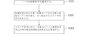
充電制御方法は、
切替信号を獲得するステップと、
前記切替信号に応じて第一充電モードまたは第二充電モードに切り替え、かつ対応するスイッチ信号を出力するステップと、
前記スイッチ信号に応じて、充電ユニットと複数の電源出力端との間の電気的接続を切断または導通するステップとを含み、前記複数の電源出力端はそれぞれ複数の二次電池と接続するのに用いられ、前記充電ユニットは前記複数の電源出力端を介して前記複数の二次電池に対して充電を行う。
The charge control method is
Obtaining a switching signal;
Switching to the first charging mode or the second charging mode according to the switching signal, and outputting a corresponding switch signal;
Disconnecting or conducting electrical connection between the charging unit and the plurality of power output terminals according to the switch signal, wherein the plurality of power output terminals are connected to the plurality of secondary batteries, respectively. The charging unit is used to charge the plurality of secondary batteries via the plurality of power output terminals.
さらに、ボタンを操作することによって前記切替信号をトリガーするか、
または、
プリセットのトリガー条件を検出した後、自動的に前記切替信号をトリガーする。
Furthermore, the switch signal is triggered by operating a button,
Or
After the preset trigger condition is detected, the switching signal is automatically triggered.
さらに、前記切替信号に応じて第一充電モードに切り替えることは、
二次電池の電池電圧の高い順に応じて順番に前記複数の二次電池を第一プリセット値に充電するステップと、
すべての二次電池に対して再度充電を行って第二プリセット値に充電するように前記充電ユニットを制御するステップとを含む。
Furthermore, switching to the first charging mode in response to the switching signal,
Charging the plurality of secondary batteries to a first preset value in order according to the order of battery voltage of the secondary batteries;
Controlling the charging unit to charge all the secondary batteries again to the second preset value.
さらに、前記二次電池の電池電圧の高い順に応じて前記複数の二次電池を第一プリセット値に充電するステップは、
(a)それぞれ前記充電ユニットと前記複数の電源出力端との間の電気的接続を導通するステップと、
(b)それぞれ前記複数の二次電池の電池電圧を検出するステップと、
(c)この電池電圧値の最も大きい二次電池を第一プリセット値に充電するように前記充電ユニットを制御するステップと、
残りの二次電池を電池電圧の高い順に応じて順番に第一プリセット値に充電するように、(a)〜(c)を繰り返すステップとを含む。
Furthermore, the step of charging the plurality of secondary batteries to a first preset value according to the order of the battery voltage of the secondary battery,
(A) conducting electrical connection between the charging unit and the plurality of power output terminals, respectively,
(B) detecting a battery voltage of each of the plurality of secondary batteries;
(C) controlling the charging unit to charge the secondary battery having the largest battery voltage value to the first preset value;
Repeating the steps (a) to (c) so as to charge the remaining secondary batteries to the first preset value in order according to the order of the battery voltage.
さらに、前記切替信号に応じて第二充電モードに切り替えることは、
(d)それぞれ前記充電ユニットと前記複数の電源出力端との間の電気的接続を導通するステップと、
(e)それぞれ前記複数の二次電池の電池電圧を検出するステップと、
(f)この電圧値の最も大きい二次電池に対して充電を行って直接に第二プリセット値に充電するように前記充電ユニットを制御するステップと、
残りの二次電池を電池電圧の高い順に応じて順番に第二プリセット値に充電するように、(d)〜(f)を繰り返すステップとを含む。
Furthermore, switching to the second charging mode in response to the switching signal,
(D) conducting electrical connection between the charging unit and the plurality of power output terminals, respectively.
(E) detecting a battery voltage of each of the plurality of secondary batteries;
(F) controlling the charging unit to charge the secondary battery having the largest voltage value and directly charge the secondary preset value;
Repeating the steps (d) to (f) so as to charge the remaining secondary batteries to the second preset value in order according to the order of the battery voltage.
充電制御回路は、
充電ユニットと、
複数であり、それぞれ複数の二次電池と接続され、かつ前記複数の二次電池に対して充電を行うのに用いられる電源出力端と、
前記充電ユニットと前記複数の電源出力端との間に接続されているスイッチユニットと、
前記スイッチユニットと電気的に接続されている制御ユニットとを含み、
前記制御ユニットが前記スイッチユニットを介して前記充電ユニットと前記複数の電源出力端との導通と切断を制御して、前記充電ユニットは、二次電池の電池電圧の高い順に応じて順番に前記複数の二次電池を第一プリセット値に充電しており、その後すべての二次電池に対して再度充電を行い、かつ第二プリセット値に充電する。
The charge control circuit
A charging unit;
A plurality of power output terminals connected to a plurality of secondary batteries and used to charge the plurality of secondary batteries;
A switch unit connected between the charging unit and the plurality of power output terminals;
A control unit electrically connected to the switch unit,
The control unit controls conduction and disconnection between the charging unit and the plurality of power output terminals via the switch unit, and the charging unit is configured to sequentially change the plurality of the charging units according to the order of the battery voltage of the secondary battery. The secondary batteries are charged to the first preset value, and then all the secondary batteries are charged again and charged to the second preset value.
さらに、前記スイッチユニットはリレースイッチ、
または、
ソース電極が前記充電ユニットと電気的に接続され、ドレイン電極が対応する電源出力端と電気的に接続され、ゲート電極が前記制御ユニットと電気的に接続される、MOSFET、
または、
コレクタ電極が前記充電ユニットと電気的に接続され、エミッタ電極が対応する電源出力端と電気的に接続され、ベース電極が前記制御ユニットと電気的に接続される、NPN型トランジスタである。
Further, the switch unit is a relay switch,
Or
A MOSFET in which a source electrode is electrically connected to the charging unit, a drain electrode is electrically connected to a corresponding power output terminal, and a gate electrode is electrically connected to the control unit;
Or
An NPN transistor in which a collector electrode is electrically connected to the charging unit, an emitter electrode is electrically connected to a corresponding power supply output terminal, and a base electrode is electrically connected to the control unit.
さらに、前記制御ユニットはフィールドプログラマブルゲートアレイであり、プログラムを制御するマイクロコントローラユニットまたはワンチップマイクロコンピュータのうちの1つが組み込まれる。 Further, the control unit is a field programmable gate array and incorporates one of a microcontroller unit for controlling a program or a one-chip microcomputer.
さらに、前記充電制御回路は電圧取得ユニットをさらに含み、この電圧取得ユニットは、前記充電ユニットと前記スイッチユニットとの間に接続され、かつ前記制御ユニットに接続されており、前記電圧取得ユニットは前記二次電池の電圧値を取得するのに用いられ、前記制御ユニットは、前記電圧取得ユニットが取得した電圧値に応じて前記スイッチユニットを介して前記複数の電源出力端と前記充電ユニットとの導通または切断を制御する。 Further, the charging control circuit further includes a voltage acquisition unit, the voltage acquisition unit is connected between the charging unit and the switch unit, and is connected to the control unit, and the voltage acquisition unit is The control unit is used to acquire a voltage value of a secondary battery, and the control unit connects the plurality of power output terminals and the charging unit via the switch unit according to the voltage value acquired by the voltage acquisition unit. Or control cutting.
さらに、前記制御ユニットは、前記スイッチユニットを介してそれぞれ前記複数の電源出力端と前記充電ユニットとの導通を制御し、よって各二次電池の電池電圧を取得するように前記電圧取得ユニットを制御する。 Further, the control unit controls conduction between the plurality of power output terminals and the charging unit via the switch unit, and thus controls the voltage acquisition unit to acquire the battery voltage of each secondary battery. To do.
さらに、前記充電ユニットは、定電流充電の方式を採用して順番に前記複数の二次電池を第一プリセット値に充電する。 Further, the charging unit employs a constant current charging method to sequentially charge the plurality of secondary batteries to the first preset value.
さらに、前記充電ユニットは定電圧充電の方式によって前記複数の二次電池を前記第一プリセット値から第二プリセット値に充電する。 Further, the charging unit charges the plurality of secondary batteries from the first preset value to the second preset value by a constant voltage charging method.
さらに、前記制御ユニットは、前記二次電池の充電電圧が前記第二プリセット値に達したときに、対応する電源出力端の給電中断を制御する。 Furthermore, the control unit controls the power supply interruption at the corresponding power output terminal when the charging voltage of the secondary battery reaches the second preset value.
充電装置は、筐体と、前記筐体内に装設される充電制御回路とを備える。この充電制御回路は、
充電ユニットと、
複数であり、それぞれ複数の二次電池と接続され、かつ前記複数の二次電池に対して充電を行うのに用いられる電源出力端と、
前記充電ユニットと前記複数の電源出力端との間に接続されているスイッチユニットと、
前記スイッチユニットと電気的に接続されている制御ユニットとを含み、
前記制御ユニットが前記スイッチユニットを介して前記充電ユニットと前記複数の電源出力端との導通と切断を制御して、前記充電ユニットは、二次電池の電池電圧の高い順に応じて順番に前記複数の二次電池を第一プリセット値に充電しており、その後すべての二次電池に対して再度充電を行い、かつ第二プリセット値に充電する。
The charging device includes a housing and a charging control circuit installed in the housing. This charge control circuit
A charging unit;
A plurality of power output terminals connected to a plurality of secondary batteries and used to charge the plurality of secondary batteries;
A switch unit connected between the charging unit and the plurality of power output terminals;
A control unit electrically connected to the switch unit,
The control unit controls conduction and disconnection between the charging unit and the plurality of power output terminals via the switch unit, and the charging unit is configured to sequentially change the plurality of the charging units according to the order of the battery voltage of the secondary battery. The secondary batteries are charged to the first preset value, and then all the secondary batteries are charged again and charged to the second preset value.
さらに、前記スイッチユニットは、リレースイッチ、
または、
ソース電極が前記充電ユニットと電気的に接続され、ドレイン電極が対応する電源出力端と電気的に接続され、ゲート電極が前記制御ユニットと電気的に接続される、MOSFET、
または、
コレクタ電極が前記充電ユニットと電気的に接続され、エミッタ電極が対応する電源出力端と電気的に接続され、ベース電極が前記制御ユニットと電気的に接続される、NPN型トランジスタである。
Further, the switch unit includes a relay switch,
Or
A MOSFET in which a source electrode is electrically connected to the charging unit, a drain electrode is electrically connected to a corresponding power output terminal, and a gate electrode is electrically connected to the control unit;
Or
An NPN transistor in which a collector electrode is electrically connected to the charging unit, an emitter electrode is electrically connected to a corresponding power supply output terminal, and a base electrode is electrically connected to the control unit.
さらに、前記制御ユニットはフィールドプログラマブルゲートアレイであり、プログラムを制御するマイクロコントローラユニットまたはワンチップマイクロコンピュータのうちの1つが組み込まれる。 Further, the control unit is a field programmable gate array and incorporates one of a microcontroller unit for controlling a program or a one-chip microcomputer.
さらに、前記充電装置は電圧取得ユニットをさらに含み、この電圧取得ユニットは、前記充電ユニットと前記スイッチユニットとの間に接続され、かつ前記制御ユニットに接続されており、前記電圧取得ユニットは前記二次電池の電圧値を取得するのに用いられ、前記制御ユニットは、前記電圧取得ユニットが取得した電圧値に応じて前記スイッチユニットを介して前記複数の電源出力端と前記充電ユニットとの導通または切断を制御する。 Further, the charging device further includes a voltage acquisition unit, the voltage acquisition unit is connected between the charging unit and the switch unit, and is connected to the control unit, and the voltage acquisition unit is The control unit is used to acquire a voltage value of a secondary battery, and the control unit connects the plurality of power output terminals and the charging unit via the switch unit according to the voltage value acquired by the voltage acquisition unit. Control cutting.
さらに、前記制御ユニットは、前記スイッチユニットを介してそれぞれ前記複数の電源出力端と前記充電ユニットとの導通を制御し、よって各二次電池の電池電圧を取得するように前記電圧取得ユニットを制御する。 Further, the control unit controls conduction between the plurality of power output terminals and the charging unit via the switch unit, and thus controls the voltage acquisition unit to acquire the battery voltage of each secondary battery. To do.
さらに、前記充電ユニットは、定電流充電の方式を採用して順番に前記複数の二次電池を第一プリセット値に充電する。 Further, the charging unit employs a constant current charging method to sequentially charge the plurality of secondary batteries to the first preset value.
さらに、前記充電ユニットは定電圧充電の方式によって前記複数の二次電池を前記第一プリセット値から第二プリセット値に充電する。 Further, the charging unit charges the plurality of secondary batteries from the first preset value to the second preset value by a constant voltage charging method.
さらに、前記制御ユニットは、前記二次電池の充電電圧が前記第二プリセット値に達したときに、対応する電源出力端の給電中断を制御する。 Furthermore, the control unit controls the power supply interruption at the corresponding power output terminal when the charging voltage of the secondary battery reaches the second preset value.
充電システムは、複数の二次電池と、前記複数の二次電池に対して充電を行うのに用いられる充電制御回路とを備える。この充電制御回路は、
充電ユニットと、
複数であり、それぞれ複数の二次電池と接続され、かつ前記複数の二次電池に対して充電を行うのに用いられる電源出力端と、
前記充電ユニットと前記複数の電源出力端との間に接続されているスイッチユニットと、
前記スイッチユニットと電気的に接続されている制御ユニットとを含み、
前記制御ユニットは前記スイッチユニットを介して前記充電ユニットと前記複数の電源出力端との導通と切断を制御し、前記充電ユニットが、二次電池の電池電圧の高い順に応じて順番に前記複数の二次電池を第一プリセット値に充電しており、その後にすべての二次電池に対して再度充電を行い、かつ第二プリセット値に充電する。
The charging system includes a plurality of secondary batteries and a charge control circuit used for charging the plurality of secondary batteries. This charge control circuit
A charging unit;
A plurality of power output terminals connected to a plurality of secondary batteries and used to charge the plurality of secondary batteries;
A switch unit connected between the charging unit and the plurality of power output terminals;
A control unit electrically connected to the switch unit,
The control unit controls conduction and disconnection between the charging unit and the plurality of power supply output terminals via the switch unit, and the charging unit is configured to sequentially change the plurality of the plurality of the plurality of power supply output terminals according to the battery voltage of the secondary battery. The secondary batteries are charged to the first preset value, and then all the secondary batteries are charged again and charged to the second preset value.
さらに、前記スイッチユニットは、リレースイッチ、
または、
ソース電極が前記充電ユニットと電気的に接続され、ドレイン電極が対応する電源出力端と電気的に接続され、ゲート電極が前記制御ユニットと電気的に接続される、MOSFET、
または、
コレクタ電極が前記充電ユニットと電気的に接続され、エミッタ電極が対応する電源出力端と電気的に接続され、ベース電極が前記制御ユニットと電気的に接続される、NPN型トランジスタである。
Further, the switch unit includes a relay switch,
Or
A MOSFET in which a source electrode is electrically connected to the charging unit, a drain electrode is electrically connected to a corresponding power output terminal, and a gate electrode is electrically connected to the control unit;
Or
An NPN transistor in which a collector electrode is electrically connected to the charging unit, an emitter electrode is electrically connected to a corresponding power supply output terminal, and a base electrode is electrically connected to the control unit.
さらに、前記制御ユニットはフィールドプログラマブルゲートアレイであり、プログラムを制御するマイクロコントローラユニットまたはワンチップマイクロコンピュータのうちの1つが組み込まれる。 Further, the control unit is a field programmable gate array and incorporates one of a microcontroller unit for controlling a program or a one-chip microcomputer.
さらに、前記充電システムは電圧取得ユニットをさらに含み、この電圧取得ユニットは、前記充電ユニットと前記スイッチユニットとの間に接続され、かつ前記制御ユニットに接続されており、前記電圧取得ユニットは前記二次電池の電圧値を取得するのに用いられ、前記制御ユニットは、前記電圧取得ユニットが取得した電圧値に応じて前記スイッチユニットの導通または切断を制御する。 Further, the charging system further includes a voltage acquisition unit, the voltage acquisition unit is connected between the charging unit and the switch unit, and is connected to the control unit, and the voltage acquisition unit is The control unit is used to acquire the voltage value of the secondary battery, and controls the conduction or disconnection of the switch unit according to the voltage value acquired by the voltage acquisition unit.
さらに、前記制御ユニットは、前記スイッチユニットを介してそれぞれ前記複数の電源出力端と前記充電ユニットとの導通を制御し、よって各二次電池の電池電圧を取得するように前記電圧取得ユニットを制御する。 Further, the control unit controls conduction between the plurality of power output terminals and the charging unit via the switch unit, and thus controls the voltage acquisition unit to acquire the battery voltage of each secondary battery. To do.
さらに、前記充電ユニットは、定電流充電の方式を採用して順番に前記複数の二次電池を第一プリセット値に充電する。 Further, the charging unit employs a constant current charging method to sequentially charge the plurality of secondary batteries to the first preset value.
さらに、前記充電ユニットは定電圧充電の方式によって前記複数の二次電池を前記第一プリセット値から第二プリセット値に充電する。 Further, the charging unit charges the plurality of secondary batteries from the first preset value to the second preset value by a constant voltage charging method.
さらに、前記制御ユニットは、前記二次電池の充電電圧が前記第二プリセット値に達したときに、対応する電源出力端の給電中断を制御する。 Furthermore, the control unit controls the power supply interruption at the corresponding power output terminal when the charging voltage of the secondary battery reaches the second preset value.
充電制御方法は、
二次電池の電池電圧の高い順に応じて順番に複数の二次電池を第一プリセット値に充電するステップと、
すべての二次電池に対して再度充電を行い、かつ第二プリセット値に充電するように充電ユニットを制御するステップとを含む。
The charge control method is
Charging a plurality of secondary batteries to a first preset value in order according to the order of the battery voltage of the secondary battery,
Charging all secondary batteries again and controlling the charging unit to charge to a second preset value.
さらに、定電流充電の方式を採用して順番に前記複数の二次電池を第一プリセット値に充電する。 Further, a constant current charging method is employed to sequentially charge the plurality of secondary batteries to the first preset value.
さらに、定電圧充電の方式によって前記複数の二次電池を前記第一プリセット値から第二プリセット値に充電する。 Further, the plurality of secondary batteries are charged from the first preset value to the second preset value by a constant voltage charging method.
さらに、前記二次電池の充電電圧が前記第二プリセット値に達したときに、対応する電源出力端の給電中断を制御する。 Further, when the charging voltage of the secondary battery reaches the second preset value, the power supply interruption at the corresponding power output terminal is controlled.
上記充電制御回路、充電装置、充電システムおよび充電制御方法は、2つの充電モードを採用することによって複数の二次電池に対して充電を行い、かつこの2つの充電モードはユーザーのニーズに応じて切替えを行うことができる。即ち高電圧電池が低電圧電池に対して大電流放電を行うのを防止して、効果的に二次電池を保護する必要がある場合、第一充電モードに切り替えることができ、ユーザーの利用を満たすように、最短の時間内に一つの二次電池をフルに充電する場合、第二充電モードに切り替えることができ、このようにして、この充電制御回路はより実用的である。 The charging control circuit, the charging device, the charging system, and the charging control method charge two or more secondary batteries by adopting two charging modes, and these two charging modes are in accordance with user needs. Switching can be performed. In other words, when it is necessary to prevent the high voltage battery from discharging a large current to the low voltage battery and effectively protect the secondary battery, it is possible to switch to the first charging mode, and to improve the user's use. When fully charging one secondary battery in the shortest time so as to satisfy, it can be switched to the second charging mode, and thus the charge control circuit is more practical.
以下のような具体的な実施形態は添付の図面に合わせてさらに本発明を説明する。 The following specific embodiments further illustrate the present invention with reference to the accompanying drawings.
以下、本発明の実施形態の図面に合わせ、本発明の実施形態の技術的解決手段に対して明確な、完全な説明を行う。説明した実施形態は、本発明の一部の実施形態であるに過ぎず、すべての実施形態ではないことは明らかである。本発明の実施形態に基づき、当業者が進歩性を有する作業をしていない前提で獲得したすべてのその他の実施形態は、いずれも本発明の保護の範囲に属する。 The following clearly and completely describes the technical solutions in the embodiments of the present invention with reference to the drawings in the embodiments of the present invention. Apparently, the described embodiments are only some embodiments of the present invention, and not all embodiments. All other embodiments obtained based on the embodiments of the present invention on the premise that a person skilled in the art does not perform inventive work belong to the protection scope of the present invention.
説明すべきなのは、一つの要素が他方の要素に「電気的に接続される」と記載されるとき、それは直接に他方の構成部品上にありまたは中間の要素が存在してもよいことである。一つの要素が他方の要素に「電気的に接続される」と見なされる場合は、それは接触接続とすることができ、例えば、導線接続の方式が可能であり、さらに非接触式接続とすることもでき、例えば、非接触式接続の方式が可能である。 It should be explained that when one element is described as “electrically connected” to the other element, it is directly on the other component or an intermediate element may be present. . If one element is considered to be “electrically connected” to the other element, it can be a contact connection, for example, a wire connection scheme is possible and a non-contact connection For example, a non-contact connection method is possible.
別途定義がある場合を除き、本文で使用したすべての技術用語および科学的用語は本発明の技術分野に属する当業者が通常に理解した意味と同じである。本文が本発明の明細書の中で使用した用語はあくまでも具体的に実施形態を説明するためのものであり、本発明を限定するものではない。本発明で使用した用語「および/または」は、一つまたは複数の関連する記載項目のあらゆる組合せである。 Except where otherwise defined, all technical and scientific terms used herein have the same meaning as commonly understood by one of ordinary skill in the art to which this invention belongs. The terminology used in the specification of the present invention is only for the purpose of describing the embodiments, and is not intended to limit the present invention. As used herein, the term “and / or” is any combination of one or more of the associated listed items.
以下、図面に合わせ、本発明の一部の実施形態に対して詳細な説明を行う。抵触がない場合は、下記の実施形態および実施形態の中の特徴を相互に組み合わせることができる。 Hereinafter, some embodiments of the present invention will be described in detail with reference to the drawings. If there is no conflict, the following embodiments and the features in the embodiments can be combined with each other.
図1を参照して、本発明の好ましい実施形態は、複数の二次電池200に対して充電を行うのに用いられる充電制御回路100を提供する。この充電制御回路100は、複数の電源出力端10、充電ユニット20、制御ユニット30、複数の前記電源出力端10と一つずつ対応するスイッチユニット40および電圧取得ユニット50を含む。
Referring to FIG. 1, a preferred embodiment of the present invention provides a
この複数の電源出力端10の間は相互に並列しかつ各電源出力端10は前記充電ユニット20と電気的に接続され、各電源出力端10と前記充電ユニット20との間にはさらに一つの前記スイッチユニット40が接続されている。
The plurality of power
前記充電ユニット20は、電源入力端、交流直流変換回路または/および直流変換回路などの回路モジュールを含むことができ、外部電源に電気的に接続し、かつこの外部電源を対応する充電電圧に処理し、そして前記電源出力端10に出力するのに用いられる。
The charging
前記制御ユニット30は、フィールドプログラマブルゲートアレイ(Field−Programmable GateArray,FPGA)であってもよく、それにプログラムを制御するマイクロコントローラユニット(Micro−Controller Unit,MCU)またはワンチップマイクロコンピュータなどが組み込まれる。前記制御ユニット30は、制御バスを介して複数の前記スイッチユニット40と電気的に接続されることができ、対応するスイッチ信号を前記スイッチユニット40に出力するのに用いられる。このスイッチユニット40は、前記制御ユニット30が送信したスイッチ信号を受信し、かつ前記スイッチ信号に応じて前記充電ユニット20と対応する電源出力端10との間の電気的接続を導通または切断し、よって前記充電ユニット20が、導通のスイッチユニット40および対応する電源出力端10を介して前記電源出力端10に電気的に接続された二次電池200に対して充電を行う。
The
前記スイッチユニット40は、金属酸化物半導体電界効果トランジスタ(Metal Oxide Semiconductor Field Effect Transistor,MOSFET)、またはリレーなど他の電子スイッチであってもよい。本実施形態では、前記スイッチユニット40がMOSFETであることを例としてスイッチユニット40の作業方式を説明する。MOSFETのソース電極は前記充電ユニット20と接続され、MOSFETのドレイン電極は対応する電源出力端10と接続され、MOSFETのゲート電極は前記制御バスを介して前記制御ユニット30と接続されている。この制御ユニット30は、MOSFETのゲート電極へハイレベル信号またはローレベル信号のような対応するスイッチ信号を送信し、よってMOSFETの導通または切断を制御する。前記MOSFETが導通されるときに、前記充電ユニット20は、導通されているMOSFETおよび対応する電源出力端10を介して二次電池200に対して充電を行うことができる。
The
他の実施形態では、前記スイッチユニット40はNPN型トランジスタなどの電子スイッチであってもよいことが理解されるであろう。例えば、前記スイッチユニット40がNPN型トランジスタである場合、このNPN型トランジスタのベース電極は制御バスを介して前記制御ユニット30と接続され、コレクタ電極は前記充電ユニット20と電気的に接続され、エミッタ電極は対応する電源出力端10と電気的に接続される。
It will be appreciated that in other embodiments, the
前記電圧取得ユニット50は、前記充電ユニット20と前記スイッチユニット40との間に電気的に接続され、かつ前記制御ユニット30と電気的に接続されている。前記電圧取得ユニット50は、各二次電池200の電圧を取得するのに用いられ、かつ取得した各二次電池200の電圧を前記制御ユニット30へ伝送する。
The
さらに、複数の前記スイッチユニット40のいずれもが切断されて、前記充電ユニット20と複数の前記電源出力端10との電気的接続を切断する場合、前記電圧取得ユニット50が取得した電圧は前記充電ユニット20の出力電圧である。複数の前記スイッチユニット40のうちの一つのスイッチユニット40が導通され、他のスイッチユニット40のいずれもが切断されたとき、前記電圧取得ユニット50が取得した電圧は、この導通状態におけるスイッチユニット40が対応する電源出力端10に接続されている二次電池200の電池電圧である。このように、前記制御ユニット30はそれぞれ前記スイッチユニット40の導通を制御することによって、それぞれ複数の前記電源出力端10に接続されている二次電池200の電池電圧を検出するように前記電圧取得ユニット50を制御する。前記制御ユニット30はさらに、前記電圧取得ユニット50が取得した電圧に応じて前記スイッチユニット40の導通と切断を制御し、さらに前記充電ユニット20と対応する電源出力端10との間の電気的接続を導通または切断する。
Furthermore, when all of the plurality of
前記充電制御回路100はモード切替ユニット70をさらに備えることが理解されるであろう。前記モード切替ユニット70は前記制御ユニット30に電気的に接続される。前記モード切替ユニット70はハイレベル信号またはローレベル信号のようなスイッチ信号を出力するのに用いられ、第一充電モードと第二充電モードとの間で切り替えるように前記充電制御回路100を制御する。例えば、前記制御ユニット30は前記モード切替ユニット70が送信したハイレベル信号を受信した場合は、前記制御ユニット30が第一充電モードで作動する。前記制御ユニット30は前記モード切替ユニット70が送信したローレベル信号を受信した場合、前記制御ユニット30は第二充電モードで作動する。
It will be understood that the charging
前記モード切替ユニット70が出力した切替信号はハードウェアまたはソフトウェアの方式によって実現できると理解されるであろう。例えば、前記モード切替ユニット70はボタンを含む。このように、前記ボタンを押したときに、前記制御ユニット30が第一充電モードに切り替えることを制御するように、前記モード切替ユニット70はハイレベル信号を前記制御ユニット30に出力する。前記ボタンが押されていない場合、前記制御ユニット30が第二充電モードに切り替えることを制御するように、前記モード切替ユニット70はローレベル信号を出力する。当然ながら、他の実施形態において、前記モード切替ユニット70は自動切替回路をさらに含み、前記自動切替回路は、プリセットのトリガー条件を検出した後に自動的に対応するハイレベル信号およびローレベル信号を出力して、前記充電制御回路100の作業モードを切り替えるのに用いられる。
It will be understood that the switching signal output by the
説明すべきなのは、前記モード切替ユニット70が出力したハイレベル信号とローレベル信号は、対応する充電モードとの間の関係を必要に応じて調整することができることである。例えば、他の実施形態において、前記モード切替ユニット70がハイレベル信号を出力するときに、前記制御ユニット30が第二充電モードに切り替えており、モード切替ユニット70がローレベル信号を出力するときに、前記制御ユニット30が第一充電モードに切り替えられるように設置することができる。当然ながら、他の実施形態において、前記充電制御回路100は以下のように設置されてもよい。前記モード切替ユニット70が何れの切替信号も前記制御ユニット30に出力していないときに、前記充電制御回路100は、現在の充電モード、例えば第一充電モードまたは第二充電モードを維持しており、前記制御ユニット30はこのモード切替ユニット70が出力した切替信号を受信すると、第一充電モードから第二充電モードに切り替えるまたは第二充電モードから第一充電モードに切り替えるような充電モードの切り替えを行う。
It should be explained that the high level signal and the low level signal output from the
さらに、前記充電制御回路100が第一充電モードで作動するときに、前記制御ユニット30はそれぞれ前記スイッチユニット40の導通を制御し、即ちそれぞれ前記複数の電源出力端10と前記充電ユニット20との導通を制御し、よって前記電圧取得ユニット50がそれぞれ複数の前記電源出力端10に接続されている二次電池200の電池電圧を検出することができる。前記制御ユニット30はさらに、前記検出した電池電圧の中の電圧値が最も大きい二次電池200と対応するスイッチユニット40の導通を制御し、かつ他のスイッチユニット40を切断することで、前記検出した電池電圧のうちの電圧値が最も大きい二次電池200と対応する電源出力端10の導通を制御し、かつ他の電源出力端10の給電が切断され、よって前記充電ユニット20が、この電圧値が最も大きい二次電池200に対して先に充電を行う。前記電圧値が最も大きい二次電池200を第一プリセット値に充電したときに、前記電圧取得ユニット50がさらにそれぞれ残りの二次電池200の電池電圧を検出する。前記制御ユニット30はさらに、残りの二次電池200の中の電圧値が最も大きい二次電池200と対応するスイッチユニット40の導通を制御し、かつその他のスイッチユニット40を切断し、よって前記充電ユニット20が、残りの二次電池200の中の電圧値が最も大きい二次電池200に対して充電し、かつ前記第一プリセット値に充電する。同様に、前記制御ユニット30は、二次電池200の電池電圧の高い順に応じて、順番に前記複数の二次電池200のいずれも第一プリセット値に充電するように前記充電ユニット20を制御する。次に、前記充電ユニット20が、すべての二次電池に対して再度充電を行い、かつ第二プリセット値に充電するように、前記制御ユニット30は前記複数のスイッチユニット40のすべての導通を制御する。
Further, when the charging
上記第一充電モードにおいて、前記充電制御回路100は電池電圧の高い順に応じてすべての二次電池200を先ず、それぞれ第一プリセット値に充電し、そして同時にすべての二次電池200に対して充電を行い、即ち並行充電を行う。複数の二次電池200が同時に充電されるときに、前記二次電池200の電池電圧値の一致を保持し、即ちいずれも第一プリセット値であり、そのため高電圧電池が低電圧電池に対して大電流放電を行うような状況が存在せず、効果的に二次電池200を保護する目的を達成し、同時に全体のシステムの充電時間を短縮する。第一充電モードにおいて、前記充電ユニット20は、定電流充電の方式を採用して順番に前記複数の二次電池200を前記第一プリセット値に充電し、そして定電圧充電の方式を採用して順番に前記複数の二次電池200を前記第一プリセット値から前記第二プリセット値に充電することが理解されるであろう。
In the first charging mode, the charging
前記充電制御回路100が第二充電モードで作動するときに、前記制御ユニット30は、それぞれ前記スイッチユニット40の導通を制御し、即ちそれぞれ前記複数の電源出力端10と前記充電ユニット20との導通を制御し、よって前記電圧取得ユニット50が、それぞれ複数の前記電源出力端10に接続されている二次電池200の電池電圧を検出することができる。前記制御ユニット30はさらに、前記検出した電池電圧の中の電圧値が最も大きい二次電池200と対応するスイッチユニット40の導通を制御し、かつ他のスイッチユニット40を切断することで、前記検出した電池電圧のうちの電圧値が最も大きい二次電池200と対応する電源出力端10の導通を制御し、かつ他の電源出力端10の給電が切断され、よって前記充電ユニット20がこの電圧値が最も大きい二次電池200に対して先に充電を行い、かつ直接に第二プリセット値に充電する。前記電池電圧値が最も大きい二次電池200がフルに充電されてから、前記電圧取得ユニット50はさらに、それぞれ残りの二次電池200の電池電圧を検出する。前記制御ユニット30はさらに、残りの二次電池200の中の電圧値が最も大きい二次電池200と対応するスイッチユニット40の導通を制御し、かつその他のスイッチユニット40を切断し、よって前記充電ユニット20が残りの二次電池200の中の電圧値が最も大きい二次電池200に対して充電し、かつ直接に第二プリセット値に充電する。同様に、前記制御ユニット30は、複数の二次電池200の電池電圧を検出することによって、かつ電池電圧の高い順に応じて順番に複数の二次電池200に対して充電を行う。
When the charging
上記第二充電モードにおいて、ユーザーの利用を満たすように、この充電制御回路100は、優先的に電圧値が最も大きい二次電池200に対して充電を行うことができ、このようにして最短の時間内で一つの二次電池200をフルに充電することができる。
In the second charging mode, the charging
本実施形態において、前記第一プリセット値が第二プリセット値より小さく、前記第二プリセット値は、二次電池200の定格出力電圧値であってもよく、または前記二次電池200の定格出力電圧の一つの電圧値よりやや大きく、例えば二次電池200の定格出力電圧値の1.2倍としてもよい。
In the present embodiment, the first preset value is smaller than the second preset value, and the second preset value may be a rated output voltage value of the
図2を参照して、本発明の実施形態で提供した充電制御回路100の充電制御方法は、以下のステップを含む:
Referring to FIG. 2, the charge control method of the
S101:切替信号を獲得する。 S101: A switching signal is acquired.
S102:前記切替信号に応じて第一充電モードまたは第二充電モードに切り替え、かつ対応するスイッチ信号を出力する。 S102: Switch to the first charging mode or the second charging mode according to the switching signal and output a corresponding switch signal.
例えば、上記電池の実施形態において、前記充電制御回路100における制御ユニット30は前記モード切替ユニット70に電気的に接続されている。前記モード切替ユニット70はハイレベル信号またはローレベル信号のような前記切替信号を出力するのに用いられ、よって前記充電制御回路100が第一充電モードと第二充電モードとの間での切り替えを制御する。例えば、前記制御ユニット30が、前記モード切替ユニット70が送信したハイレベル信号を受信したときに、前記制御ユニット30は第一充電モードで作動する。前記制御ユニット30が、前記モード切替ユニット70が送信したローレベル信号を受信したときに、前記制御ユニット30が第二充電モードに切り替える。
For example, in the battery embodiment, the
前記モード切替ユニット70が出力した切替信号はハードウェアまたはソフトウェアの方式によって実現することができると理解されるであろう。例えば、前記モード切替ユニット70はボタンを含む。このように、前記ボタンを押したときに、前記制御ユニット30は、前記モード切替ユニット70が送信したハイレベル信号を受信することができ、前記制御ユニット30は第一充電モードに切り替える。前記ボタンが押されていない場合は、前記制御ユニット30は、前記モード切替ユニット70が送信したローレベル信号を受信することができ、前記制御ユニット30は第二充電モードに切り替える。当然ながら、他の実施形態において、前記モード切替ユニット70は自動切替回路をさらに含み、前記自動切替回路はプリセットのトリガー条件を検出した後に自動的に対応するハイレベル信号およびローレベル信号を出力し、よって前記充電制御回路100の作業モードを切り替える。
It will be understood that the switching signal output from the
S103:前記スイッチ信号に応じて、前記充電ユニット20と前記電源出力端10との間の電気的接続を切断または導通する。
S103: The electrical connection between the charging
例えば、上記電池の実施形態において、前記充電制御回路100はスイッチユニット40をさらに含み、前記スイッチユニット40は、前記充電ユニット20と対応する前記電源出力端10との間に接続され、前記スイッチユニット40を導通または切断することによって、前記充電ユニット20と前記電源出力端10との間の電気的接続を切断または導通する。
For example, in the embodiment of the battery, the charging
前記充電制御回路100は電圧取得ユニット50をさらに含み、前記制御ユニット30は、それぞれ前記スイッチユニット40の導通を制御し、即ち前記複数の電源出力端10と前記充電ユニット20との導通を制御することによって、各二次電池200の電池電圧を取得するように前記電圧取得ユニット50を制御し、かつ取得した電圧値に応じて前記スイッチユニット40の導通または切断を制御する。
The charging
図3を併せて参照して、前記切替信号に応じて第一充電モードに切り替えたときに、前記S102は以下を含む:
S104:二次電池200の電池電圧の高い順に応じて順番に前記二次電池200を第一プリセット値に充電する。
Referring also to FIG. 3, when switching to the first charging mode according to the switching signal, the S102 includes the following:
S104: The
さらに、S104は具体的に以下を含む: In addition, S104 specifically includes:
S1041:それぞれ前記充電ユニット20と前記複数の電源出力端10との間の電気的接続を導通するように、それぞれ前記スイッチユニット40の導通を制御する。
S1041: The conduction of the
S1042:それぞれ複数の前記二次電池200の電池電圧を検出する。
S1042: The battery voltages of the plurality of
S1043:この電池電圧値が最も大きい二次電池を第一プリセット値に充電するように前記充電ユニット20を制御する。
S1043: The charging
S1044:残りの二次電池200を電池電圧の高い順に応じて順番に第一プリセット値に充電するように、S1041〜S1043を繰り返す。
S1044: S1041 to S1043 are repeated so that the remaining
S105:すべての二次電池200に対して再度充電を行い、かつ第二プリセット値に充電するように前記充電ユニット20を制御する。
S105: The charging
第一充電モードにおいて、前記充電ユニット20は、定電流充電の方式を採用して順番に前記複数の二次電池200を前記第一プリセット値に充電し、そして定電圧充電の方式を採用して順番に前記複数の二次電池200を前記第一プリセット値から前記第二プリセット値に充電してもよいことが理解されるであろう。
In the first charging mode, the charging
図4を併せて参照して、前記制御ユニット30が前記切替信号に応じて第二充電モードに切り替えたときに、前記方法は以下を含む。
Referring also to FIG. 4, when the
S106:それぞれ前記充電ユニット20と前記複数の電源出力端10との間の電気的接続を導通するように、それぞれ前記スイッチユニット40の導通を制御する。
S106: Control the conduction of the
S107:それぞれ複数の前記二次電池200の電池電圧を検出する。
S107: The battery voltages of the plurality of
S108:検出した電池電圧の中の電圧値が最も大きい二次電池200に対して先に充電を行い、かつ直接に第二プリセット値に充電するように前記充電ユニット20を制御する。
S108: The charging
S109:残りの二次電池200を電池電圧の高い順に応じて順番に第二プリセット値に充電するように、S106〜S108を繰り返す。
S109: S106 to S108 are repeated so that the remaining
本実施形態において、前記第一プリセット値は第二プリセット値より小さく、前記第二プリセット値は、二次電池200の定格出力電圧値であってもよく、または前記二次電池200の定格出力電圧の一つの電圧値よりやや大きく、例えば二次電池200の定格出力電圧値の1.2倍としてもよい。
In the present embodiment, the first preset value is smaller than the second preset value, and the second preset value may be a rated output voltage value of the
図5を併せて参照して、他の実施形態において、前記スイッチユニット40は、多岐路スイッチが集積されているスイッチチップであってもよく、前記電源出力端10はパラレル・ポートであってもよい。そのため、前記スイッチユニット40および電源出力端10の数のいずれも一つにまで減らすことができ、前記電源出力端10の各ポートをそれぞれ前記スイッチユニット40の各岐路スイッチに接続すればよい。
Referring also to FIG. 5, in another embodiment, the
上記充電制御回路100は筐体(図示せず)内に装設されることができ、さらにこの筐体と共同して一つの充電装置を構成することが理解されるであろう。さらに、前記充電装置は前記複数の二次電池200と共同して一つの充電システムを構成する。
It will be understood that the charging
図6を併せて参照して、前記充電システムは、移動可能な装置300に応用可能であることが理解されるであろう。この移動可能な装置300は車両、船などであってもよい。この移動可能な装置300は動力装置301をさらに含む。前記充電システムは、前記動力装置301と電気的に接続され、前記動力装置301に電気エネルギーを提供するのに用いられる。
Referring also to FIG. 6, it will be appreciated that the charging system is applicable to a
図7を併せて参照して、そのうちの一実施形態において、この移動可能な装置300は無人航空機である。この動力装置301は電子速度制御装置303、モーター305およびプロペラ307を含む。前記電子速度制御装置303は、前記モーター305に電気的に接続され、前記モーター305の回転速度を制御するのに用いられる。前記プロペラ307は、前記モーター305に取り付けられ、かつ前記モーター305の駆動で、前記無人航空機300の飛行を駆動する。前記充電システムは、前記電子速度制御装置303に電気的に接続され、前記動力装置301に電気エネルギーを提供する。
Referring also to FIG. 7, in one embodiment, this
上記はあくまでも本発明の実施形態であって、本発明の特許請求の範囲を限定することはなく、本発明の明細書および図面内容を利用して実施した同等の構造または同等のプロセスの変換、または直接または間接にその他の関連する技術分野における応用は、いずれも同様な理由で本発明の特許請求の範囲に含まれる。 The above is only an embodiment of the present invention, and does not limit the scope of the claims of the present invention, and the equivalent structure or process conversion performed using the specification and drawings of the present invention, Any application in other related technical fields, either directly or indirectly, is within the scope of the present invention for the same reason.
100 充電制御回路
10 電源出力端
20 充電ユニット
30 制御ユニット
40 スイッチユニット
50 電圧取得ユニット
70 モード切替ユニット
200 二次電池
300 移動可能な装置
301 動力装置
303 電子速度制御装置
305 モーター
307 プロペラ
DESCRIPTION OF
Claims (68)
充電ユニットと、
複数であり、それぞれ複数の二次電池と接続され、かつ前記複数の二次電池に対して充電を行うのに用いられる電源出力端と、
前記充電ユニットと前記複数の電源出力端との間に接続されているスイッチユニットと、
前記スイッチユニットと電気的に接続されている制御ユニットと、
前記制御ユニットと電気的に接続されているモード切替ユニットとを備え、
前記制御ユニットは、前記モード切替ユニットが送信した切替信号に応じて第一充電モードまたは第二充電モードに切り替え、かつ対応するスイッチ信号を前記スイッチユニットに出力しており、前記スイッチユニットは、前記スイッチ信号に応じて前記充電ユニットと前記複数の電源出力端との間の電気的接続を切断または導通することを特徴とする充電制御回路。 A charge control circuit,
A charging unit;
A plurality of power output terminals connected to a plurality of secondary batteries and used to charge the plurality of secondary batteries;
A switch unit connected between the charging unit and the plurality of power output terminals;
A control unit electrically connected to the switch unit;
A mode switching unit electrically connected to the control unit;
The control unit switches to the first charging mode or the second charging mode according to the switching signal transmitted by the mode switching unit, and outputs a corresponding switch signal to the switch unit, the switch unit, A charge control circuit that disconnects or conducts electrical connection between the charging unit and the plurality of power supply output terminals in accordance with a switch signal.
または、
ソース電極が前記充電ユニットと電気的に接続され、ドレイン電極が対応する電源出力端と電気的に接続され、ゲート電極が前記制御ユニットと電気的に接続される、MOSFET、
または、
コレクタ電極が前記充電ユニットと電気的に接続され、エミッタ電極が対応する電源出力端と電気的に接続され、ベース電極が前記制御ユニットと電気的に接続される、NPN型トランジスタであることを特徴とする請求項1に記載の充電制御回路。 The switch unit is a relay switch,
Or
A MOSFET in which a source electrode is electrically connected to the charging unit, a drain electrode is electrically connected to a corresponding power output terminal, and a gate electrode is electrically connected to the control unit;
Or
A collector electrode is electrically connected to the charging unit, an emitter electrode is electrically connected to a corresponding power supply output terminal, and a base electrode is an NPN transistor electrically connected to the control unit. The charge control circuit according to claim 1.
または、
前記モード切替ユニットは自動切替回路を備え、前記自動切替回路は、プリセットのトリガー条件を検出した後に自動的に前記切替信号を出力するのに用いられることを特徴とする請求項1または4に記載の充電制御回路。 The mode switching unit includes a button, and outputs the switching signal by operating the button.
Or
5. The mode switching unit includes an automatic switching circuit, and the automatic switching circuit is used to automatically output the switching signal after detecting a preset trigger condition. Charge control circuit.
該充電制御回路は、充電ユニットと、
複数であり、それぞれ充電される複数の二次電池と接続され、かつ前記複数の二次電池に対して充電を行う電源出力端と、
前記充電ユニットと前記複数の電源出力端との間に接続されているスイッチユニットと、
前記スイッチユニットと電気的に接続されている制御ユニットと、
前記制御ユニットと電気的に接続されているモード切替ユニットとを備え、
前記制御ユニットは、前記モード切替ユニットが送信した切替信号に応じて第一充電モードまたは第二充電モードに切り替え、かつ対応するスイッチ信号を前記スイッチユニットに出力しており、前記スイッチユニットは、前記スイッチ信号に応じて前記充電ユニットと前記複数の電源出力端との間の電気的接続を切断または導通することを特徴とする充電装置。 A charging device comprising a housing and a charge control circuit installed in the housing,
The charging control circuit includes a charging unit;
A plurality of power supply output terminals that are connected to a plurality of secondary batteries to be charged and charge the plurality of secondary batteries; and
A switch unit connected between the charging unit and the plurality of power output terminals;
A control unit electrically connected to the switch unit;
A mode switching unit electrically connected to the control unit;
The control unit switches to the first charging mode or the second charging mode according to the switching signal transmitted by the mode switching unit, and outputs a corresponding switch signal to the switch unit, the switch unit, A charging device that disconnects or conducts electrical connection between the charging unit and the plurality of power output terminals in response to a switch signal.
または、
ソース電極が前記充電ユニットと電気的に接続され、ドレイン電極が対応する電源出力端と電気的に接続され、ゲート電極が前記制御ユニットと電気的に接続されている、MOSFET、
または、
コレクタ電極が前記充電ユニットと電気的に接続され、エミッタ電極が対応する電源出力端と電気的に接続され、ベース電極が前記制御ユニットと電気的に接続されている、NPN型トランジスタであることを特徴とする請求項13に記載の充電装置。 The switch unit is a relay switch,
Or
A MOSFET in which a source electrode is electrically connected to the charging unit, a drain electrode is electrically connected to a corresponding power output terminal, and a gate electrode is electrically connected to the control unit;
Or
An NPN transistor having a collector electrode electrically connected to the charging unit, an emitter electrode electrically connected to a corresponding power supply output terminal, and a base electrode electrically connected to the control unit; The charging device according to claim 13.
または、
前記モード切替ユニットは自動切替回路を備え、前記自動切替回路はプリセットのトリガー条件を検出した後に自動的に前記切替信号を出力するのに用いられることを特徴とする請求項13または16に記載の充電装置。 The mode switching unit includes a button, and outputs the switching signal by operating the button.
Or
17. The mode switching unit includes an automatic switching circuit, and the automatic switching circuit is used to automatically output the switching signal after detecting a preset trigger condition. Charging device.
前記充電制御回路は、
充電ユニットと、
複数であり、それぞれ複数の二次電池と接続され、かつ前記複数の二次電池に対して充電を行う電源出力端と、
前記充電ユニットと前記複数の電源出力端との間に接続されているスイッチユニットと、
前記スイッチユニットと電気的に接続されている制御ユニットと、
前記制御ユニットと電気的に接続されているモード切替ユニットとを備え、
前記制御ユニットは、前記モード切替ユニットが送信した切替信号に応じて第一充電モードまたは第二充電モードに切り替え、かつ対応するスイッチ信号を前記スイッチユニットに出力しており、前記スイッチユニットは、前記スイッチ信号に応じて前記充電ユニットと前記複数の電源出力端との間の電気的接続を切断または導通することを特徴とする充電システム。 A charging system comprising a plurality of secondary batteries and a charge control circuit for charging the plurality of secondary batteries,
The charge control circuit includes:
A charging unit;
A plurality of power supply output terminals connected to a plurality of secondary batteries and charging the plurality of secondary batteries,
A switch unit connected between the charging unit and the plurality of power output terminals;
A control unit electrically connected to the switch unit;
A mode switching unit electrically connected to the control unit;
The control unit switches to the first charging mode or the second charging mode according to the switching signal transmitted by the mode switching unit, and outputs a corresponding switch signal to the switch unit, the switch unit, A charging system characterized by disconnecting or conducting electrical connection between the charging unit and the plurality of power supply output terminals in accordance with a switch signal.
または、
ソース電極が前記充電ユニットと電気的に接続され、ドレイン電極が対応する電源出力端と電気的に接続され、ゲート電極が前記制御ユニットと電気的に接続される、MOSFET、
または、
コレクタ電極が前記充電ユニットと電気的に接続され、エミッタ電極が対応する電源出力端と電気的に接続され、ベース電極が前記制御ユニットと電気的に接続される、NPN型トランジスタであることを特徴とする請求項25に記載の充電システム。 The switch unit is a relay switch,
Or
A MOSFET in which a source electrode is electrically connected to the charging unit, a drain electrode is electrically connected to a corresponding power output terminal, and a gate electrode is electrically connected to the control unit;
Or
A collector electrode is electrically connected to the charging unit, an emitter electrode is electrically connected to a corresponding power supply output terminal, and a base electrode is an NPN transistor electrically connected to the control unit. The charging system according to claim 25.
または、
前記モード切替ユニットは自動切替回路を備え、前記自動切替回路は、プリセットのトリガー条件を検出した後に自動的に前記切替信号を出力するのに用いられることを特徴とする請求項25または28に記載の充電システム。 The mode switching unit includes a button, and outputs the switching signal by operating the button.
Or
29. The mode switching unit includes an automatic switching circuit, and the automatic switching circuit is used to automatically output the switching signal after detecting a preset trigger condition. Charging system.
切替信号を獲得するステップと、
前記切替信号に応じて第一充電モードまたは第二充電モードに切り替え、かつ対応するスイッチ信号を出力するステップと、
前記スイッチ信号に応じて、充電ユニットと複数の電源出力端との間の電気的接続を切断または導通するステップとを含み、前記複数の電源出力端はそれぞれ複数の二次電池と接続するのに用いられ、前記充電ユニットは前記複数の電源出力端を介して前記複数の二次電池に対して充電を行うことを特徴とする充電制御方法。 A charge control method comprising:
Obtaining a switching signal;
Switching to the first charging mode or the second charging mode according to the switching signal, and outputting a corresponding switch signal;
Disconnecting or conducting electrical connection between the charging unit and the plurality of power output terminals according to the switch signal, wherein the plurality of power output terminals are connected to the plurality of secondary batteries, respectively. A charging control method, wherein the charging unit is used to charge the plurality of secondary batteries via the plurality of power output terminals.
または、
プリセットのトリガー条件を検出した後、自動的に前記切替信号をトリガーすることを特徴とする請求項37に記載の充電制御方法。 Trigger the switching signal by operating one button,
Or
38. The charge control method according to claim 37, wherein the switching signal is automatically triggered after detecting a preset trigger condition.
二次電池の電池電圧の高い順に応じて順番に前記複数の二次電池を第一プリセット値に充電するステップと、
すべての二次電池に対して再度充電を行って第二プリセット値へ充電に充電するように前記充電ユニットを制御するステップとを含むことを特徴とする請求項37に記載の充電制御方法。 Switching to the first charging mode according to the switching signal,
Charging the plurality of secondary batteries to a first preset value in order according to the order of battery voltage of the secondary batteries;
38. The charge control method according to claim 37, further comprising the step of charging the second rechargeable battery again and controlling the charging unit to charge to the second preset value.
(a)それぞれ前記充電ユニットと前記複数の電源出力端との間の電気的接続を導通するステップと、
(b)それぞれ前記複数の二次電池の電池電圧を検出するステップと、
(c)前記電池電圧値の最も大きい二次電池を第一プリセット値に充電するように前記充電ユニットを制御するステップと、
残りの二次電池を電池電圧の高い順に応じて順番に第一プリセット値に充電するように、(a)〜(c)を繰り返すステップとを含むことを特徴とする請求項39に記載の充電制御方法。 The step of charging the plurality of secondary batteries to the first preset value in order according to the order of the battery voltage of the secondary battery,
(A) conducting electrical connection between the charging unit and the plurality of power output terminals, respectively,
(B) detecting a battery voltage of each of the plurality of secondary batteries;
(C) controlling the charging unit to charge the secondary battery having the largest battery voltage value to a first preset value;
40. The charging according to claim 39, further comprising the steps of repeating (a) to (c) so as to charge the remaining secondary batteries to the first preset value in order according to the order of the battery voltage. Control method.
(d)それぞれ前記充電ユニットと前記複数の電源出力端との間の電気的接続を導通するステップと、
(e)それぞれ前記複数の二次電池の電池電圧を検出するステップと、
(f)前記電圧値の最も大きい二次電池に対して先に充電を行って直接に第二プリセット値に充電するように前記充電ユニットを制御するステップと、
残りの二次電池を電池電圧の高い順に応じて順番に第二プリセット値に充電するように、(d)〜(f)を繰り返すステップとを含むことを特徴とする請求項37に記載の充電制御方法。 Switching to the second charging mode according to the switching signal,
(D) conducting electrical connection between the charging unit and the plurality of power output terminals, respectively.
(E) detecting a battery voltage of each of the plurality of secondary batteries;
(F) controlling the charging unit to charge the secondary battery having the largest voltage value first and directly charge to the second preset value;
The step of repeating (d) to (f) so as to charge the remaining secondary batteries to the second preset value in order according to the order of the battery voltage. Control method.
充電ユニットと、
複数であり、それぞれ複数の二次電池と接続され、かつ前記複数の二次電池に対して充電を行うのに用いられる電源出力端と、
前記充電ユニットと前記複数の電源出力端との間に接続されているスイッチユニットと、
前記スイッチユニットと電気的に接続されている制御ユニットとを備え、
前記制御ユニットが、前記スイッチユニットを介して前記充電ユニットと前記複数の電源出力端との導通と切断を制御して、前記充電ユニットは、二次電池の電池電圧の高い順に応じて順番に前記複数の二次電池を第一プリセット値に充電するようにし、その後にすべての二次電池に対して再度充電を行い、かつ第二プリセット値に充電することを特徴とする充電制御回路。 A charge control circuit,
A charging unit;
A plurality of power output terminals connected to a plurality of secondary batteries and used to charge the plurality of secondary batteries;
A switch unit connected between the charging unit and the plurality of power output terminals;
A control unit electrically connected to the switch unit,
The control unit controls conduction and disconnection between the charging unit and the plurality of power supply output terminals via the switch unit, and the charging unit is configured in order according to the battery voltage of the secondary battery in descending order. A charge control circuit characterized in that a plurality of secondary batteries are charged to a first preset value, then all the secondary batteries are charged again and charged to a second preset value.
または、
ソース電極が前記充電ユニットと電気的に接続され、ドレイン電極が対応する電源出力端と電気的に接続され、ゲート電極が前記制御ユニットと電気的に接続される、MOSFET、
または、
コレクタ電極が前記充電ユニットと電気的に接続され、エミッタ電極が対応する電源出力端と電気的に接続され、ベース電極が前記制御ユニットと電気的に接続される、NPN型トランジスタであることを特徴とする請求項42に記載の充電制御回路。 The switch unit is a relay switch,
Or
A MOSFET in which a source electrode is electrically connected to the charging unit, a drain electrode is electrically connected to a corresponding power output terminal, and a gate electrode is electrically connected to the control unit;
Or
A collector electrode is electrically connected to the charging unit, an emitter electrode is electrically connected to a corresponding power supply output terminal, and a base electrode is an NPN transistor electrically connected to the control unit. The charge control circuit according to claim 42.
該充電制御回路は、充電ユニットと、
複数であり、それぞれ複数の二次電池と接続され、かつ前記複数の二次電池に対して充電を行う電源出力端と、
前記充電ユニットと前記複数の電源出力端との間に接続されているスイッチユニットと、
前記スイッチユニットと電気的に接続されている制御ユニットとを備え、
前記制御ユニットは、前記スイッチユニットを介して前記充電ユニットと前記複数の電源出力端との導通と切断を制御して、前記充電ユニットが二次電池の電池電圧の高い順に応じて順番に前記複数の二次電池を第一プリセット値に充電し、その後にすべての二次電池に対して再度充電を行い、かつ第二プリセット値に充電することを特徴とする充電装置。 A charging device comprising a housing and a charge control circuit installed in the housing,
The charging control circuit includes a charging unit;
A plurality of power supply output terminals connected to a plurality of secondary batteries and charging the plurality of secondary batteries,
A switch unit connected between the charging unit and the plurality of power output terminals;
A control unit electrically connected to the switch unit,
The control unit controls conduction and disconnection between the charging unit and the plurality of power supply output ends via the switch unit, and the charging unit sequentially turns the plurality of the plurality of the charging units according to the order of the battery voltage of the secondary battery. The secondary battery is charged to the first preset value, then all the secondary batteries are charged again, and charged to the second preset value.
または、
ソース電極が前記充電ユニットと電気的に接続され、ドレイン電極が対応する電源出力端と電気的に接続され、ゲート電極が前記制御ユニットと電気的に接続される、MOSFET、
または、
コレクタ電極が前記充電ユニットと電気的に接続され、エミッタ電極が対応する電源出力端と電気的に接続され、ベース電極が前記制御ユニットと電気的に接続される、NPN型トランジスタであることを特徴とする請求項50に記載の充電装置。 The switch unit is a relay switch,
Or
A MOSFET in which a source electrode is electrically connected to the charging unit, a drain electrode is electrically connected to a corresponding power output terminal, and a gate electrode is electrically connected to the control unit;
Or
A collector electrode is electrically connected to the charging unit, an emitter electrode is electrically connected to a corresponding power supply output terminal, and a base electrode is an NPN transistor electrically connected to the control unit. The charging device according to claim 50.
充電ユニットと、
複数であり、それぞれ複数の二次電池と接続され、かつ前記複数の二次電池に対して充電を行う電源出力端と、
前記充電ユニットと前記複数の電源出力端との間に接続されているスイッチユニットと、
前記スイッチユニットと電気的に接続されている制御ユニットとを備え、
前記制御ユニットが、前記スイッチユニットを介して前記充電ユニットと前記複数の電源出力端との導通または切断を制御して、前記充電ユニットが、二次電池の電池電圧の高い順に応じて順番に前記複数の二次電池を第一プリセット値に充電しており、その後にすべての二次電池に対して再度充電を行い、かつ第二プリセット値に充電することを特徴とする充電システム。 A charging system comprising a plurality of secondary batteries and a charge control circuit used to charge the plurality of secondary batteries, wherein the charge control circuit comprises:
A charging unit;
A plurality of power supply output terminals connected to a plurality of secondary batteries and charging the plurality of secondary batteries,
A switch unit connected between the charging unit and the plurality of power output terminals;
A control unit electrically connected to the switch unit,
The control unit controls conduction or disconnection between the charging unit and the plurality of power supply output terminals via the switch unit, and the charging unit is sequentially configured according to the battery voltage of the secondary battery in descending order. A charging system characterized in that a plurality of secondary batteries are charged to a first preset value, and thereafter all the secondary batteries are charged again and charged to a second preset value.
または、
ソース電極が前記充電ユニットと電気的に接続され、ドレイン電極が対応する電源出力端と電気的に接続され、ゲート電極が前記制御ユニットと電気的に接続される、MOSFET、
または、
コレクタ電極が前記充電ユニットと電気的に接続され、エミッタ電極が対応する電源出力端と電気的に接続され、ベース電極が前記制御ユニットと電気的に接続される、NPN型トランジスタであることを特徴とする請求項58に記載の充電システム。 The switch unit is a relay switch,
Or
A MOSFET in which a source electrode is electrically connected to the charging unit, a drain electrode is electrically connected to a corresponding power output terminal, and a gate electrode is electrically connected to the control unit;
Or
A collector electrode is electrically connected to the charging unit, an emitter electrode is electrically connected to a corresponding power supply output terminal, and a base electrode is an NPN transistor electrically connected to the control unit. The charging system according to claim 58.
二次電池の電池電圧の高い順に応じて順番に複数の二次電池を第一プリセット値に充電するステップと、
すべての二次電池に対して再度充電を行って第二プリセット値に充電するように充電ユニットを制御するステップとを含むことを特徴とする充電制御方法。 A charge control method comprising:
Charging a plurality of secondary batteries to a first preset value in order according to the order of the battery voltage of the secondary battery,
Charging the second rechargeable battery and controlling the charging unit to charge to the second preset value.
Applications Claiming Priority (1)
| Application Number | Priority Date | Filing Date | Title |
|---|---|---|---|
| PCT/CN2015/082827 WO2017000216A1 (en) | 2015-06-30 | 2015-06-30 | Charging control circuit, charging device, charging system and charging control method |
Publications (1)
| Publication Number | Publication Date |
|---|---|
| JP2017525323A true JP2017525323A (en) | 2017-08-31 |
Family
ID=57607465
Family Applications (1)
| Application Number | Title | Priority Date | Filing Date |
|---|---|---|---|
| JP2016546089A Pending JP2017525323A (en) | 2015-06-30 | 2015-06-30 | Charging control circuit, charging device, charging system and charging control method |
Country Status (5)
| Country | Link |
|---|---|
| US (1) | US10587128B2 (en) |
| EP (1) | EP3319196B1 (en) |
| JP (1) | JP2017525323A (en) |
| CN (1) | CN107112767B (en) |
| WO (1) | WO2017000216A1 (en) |
Cited By (1)
| Publication number | Priority date | Publication date | Assignee | Title |
|---|---|---|---|---|
| JP2021522668A (en) * | 2018-06-22 | 2021-08-30 | ボーンズ、インコーポレイテッド | Circuit breaker |
Families Citing this family (6)
| Publication number | Priority date | Publication date | Assignee | Title |
|---|---|---|---|---|
| WO2018222261A1 (en) * | 2017-06-01 | 2018-12-06 | Florida Atlantic University Board Of Trustees | Systems and methods for federated power management |
| CN109159674B (en) * | 2018-09-03 | 2020-08-21 | 广东嘉腾机器人自动化有限公司 | Charging circuit and system |
| US11025072B2 (en) | 2018-10-17 | 2021-06-01 | Ess Tech, Inc. | System and method for operating an electrical energy storage system |
| CN111884272A (en) * | 2019-05-03 | 2020-11-03 | 深圳市倍斯特科技股份有限公司 | Charging method |
| CN110676898B (en) * | 2019-09-16 | 2023-06-02 | Oppo广东移动通信有限公司 | Equipment to be charged |
| CN111682615A (en) * | 2020-06-18 | 2020-09-18 | 格力博(江苏)股份有限公司 | Charging control circuit, charging device and charging system |
Citations (4)
| Publication number | Priority date | Publication date | Assignee | Title |
|---|---|---|---|---|
| JPH0287937A (en) * | 1988-09-21 | 1990-03-28 | Sanyo Electric Co Ltd | Charging equipment |
| JPH06303729A (en) * | 1993-04-13 | 1994-10-28 | Sony Corp | Charger |
| JPH09215217A (en) * | 1996-02-07 | 1997-08-15 | Sony Corp | Apparatus and method for charging of battery |
| JPH11191933A (en) * | 1997-10-20 | 1999-07-13 | Fujitsu Ltd | Battery charging device and method and electronic equipment |
Family Cites Families (104)
| Publication number | Priority date | Publication date | Assignee | Title |
|---|---|---|---|---|
| US4849682A (en) * | 1987-10-30 | 1989-07-18 | Anton/Bauer, Inc. | Battery charging system |
| US5057762A (en) * | 1990-07-30 | 1991-10-15 | Motorola, Inc. | System for determining battery charge states and charging sequence for a battery charger |
| US5218286A (en) * | 1991-09-16 | 1993-06-08 | Monarch Marking Systems, Inc. | Multichannel battery charger |
| JPH0997629A (en) * | 1995-09-29 | 1997-04-08 | Sanyo Electric Co Ltd | Plural lithium ion secondary battery charging method |
| US5780991A (en) * | 1996-07-26 | 1998-07-14 | Telxon Corporation | Multiple station charging apparatus with single charging power supply for parallel charging |
| JP3208655B2 (en) * | 1996-08-13 | 2001-09-17 | 富士通電装株式会社 | Charging device for electric vehicles |
| US5914606A (en) * | 1996-10-10 | 1999-06-22 | Becker-Irvin; Craig H. | Battery cell voltage monitor and method |
| US6137261A (en) * | 1998-01-26 | 2000-10-24 | Physio-Control Manufacturing Corporation | Rechargeable battery maintenance and testing system |
| KR100793194B1 (en) * | 2001-07-05 | 2008-01-10 | 엘지전자 주식회사 | An apparatus and method for charging multi battery |
| JP3886389B2 (en) * | 2002-02-07 | 2007-02-28 | 株式会社リコー | Battery pack charging device and charging method |
| JP2003288951A (en) * | 2002-03-27 | 2003-10-10 | Fuji Heavy Ind Ltd | Charging method for lead storage battery |
| TW571452B (en) | 2002-12-13 | 2004-01-11 | Quanta Comp Inc | Charging-type electrical potential balance device |
| JP2004357481A (en) * | 2003-05-30 | 2004-12-16 | Sanyo Electric Co Ltd | Method of charging a plurality of batteries, and method of discharging |
| US7081737B2 (en) * | 2003-06-19 | 2006-07-25 | O2Micro International Limited | Battery cell monitoring and balancing circuit |
| US7859224B2 (en) * | 2005-05-26 | 2010-12-28 | Shop-Vac Corporation | Charge control circuit for a vehicle vacuum cleaner battery |
| US7456611B2 (en) * | 2005-08-11 | 2008-11-25 | Semiconductor Components Industries, L.L.C. | Multi-current battery charger circuit and method therefor |
| CN102655342B (en) * | 2006-03-03 | 2016-04-06 | 联想创新有限公司(香港) | Power-supply system |
| US7839121B2 (en) * | 2006-03-20 | 2010-11-23 | Lg Electronics Inc. | Apparatus and method for managing power of battery packs in a portable device |
| US7679335B1 (en) * | 2006-07-07 | 2010-03-16 | Collins Ralph C | Battery charger for aircraft emergency egress batteries |
| CN201017967Y (en) * | 2007-03-05 | 2008-02-06 | 南京德朔实业有限公司 | Lithium cell system with self-charging function |
| JP5118913B2 (en) * | 2007-07-24 | 2013-01-16 | トヨタ自動車株式会社 | Power supply system, electric vehicle equipped with the same, and control method of power supply system |
| JP5146726B2 (en) * | 2007-10-25 | 2013-02-20 | 日立工機株式会社 | Charger |
| US8169191B2 (en) * | 2008-02-25 | 2012-05-01 | Werthman Dean A | System for use in gathering or processing data in a healthcare facility having fleet of mobile workstations |
| US7830668B2 (en) * | 2008-02-25 | 2010-11-09 | Stinger Industries LLC | Power supply unit for mobile workstation and method |
| US7782607B2 (en) * | 2008-02-25 | 2010-08-24 | Stinger Industries LLC | Mobile workstation having power system with removable battery configured for drop-in engagement therewith |
| US8160727B2 (en) * | 2008-02-25 | 2012-04-17 | Gary Coonan | Mobile workstation control system configured for power system and peripheral device control |
| US7855530B2 (en) * | 2008-02-25 | 2010-12-21 | Stinger Industries, Llc | Battery charging system and method of reducing variation in battery charging cycle count |
| US7800255B2 (en) * | 2008-02-25 | 2010-09-21 | Stinger Industries LLC | Power system for mobile workstation and method |
| US8775828B2 (en) * | 2008-02-25 | 2014-07-08 | Gary Coonan | Power control system for mobile workstation and method |
| US8227943B2 (en) * | 2008-02-25 | 2012-07-24 | Lee Melvin Harbin | Power system retrofit kit for mobile workstation and retrofit method |
| US8519671B2 (en) * | 2008-09-15 | 2013-08-27 | Blackberry Limited | Power supply circuit and method for providing output voltage to charge a battery |
| US20110266993A1 (en) * | 2008-11-10 | 2011-11-03 | Himangshu Rai Vaish | Systems and methods for solar based battery charging |
| CN101740732B (en) * | 2008-11-12 | 2012-09-19 | 深圳富泰宏精密工业有限公司 | Battery fixing device |
| US7612997B1 (en) * | 2008-11-17 | 2009-11-03 | Incase Designs Corp. | Portable electronic device case with battery |
| JP5326517B2 (en) * | 2008-11-21 | 2013-10-30 | ソニー株式会社 | Integrated circuit and battery pack using the same |
| US9762069B2 (en) * | 2009-05-19 | 2017-09-12 | Duracell U.S. Operations, Inc. | Multi-use fast rate charging stand |
| US9197081B2 (en) * | 2009-08-28 | 2015-11-24 | The Charles Stark Draper Laboratory, Inc. | High-efficiency battery equalization for charging and discharging |
| KR100946635B1 (en) * | 2009-09-16 | 2010-03-09 | 제이엠씨엔지니어링 주식회사 | The apparatus of battery pack to have a four terminal network charging moudle of multi channel and power supply moudle of multi channel |
| US20110193518A1 (en) * | 2010-02-10 | 2011-08-11 | James Wright | Battery override |
| US8415923B2 (en) * | 2010-04-23 | 2013-04-09 | Psion Inc. | External battery charging unit |
| DE102010040721A1 (en) * | 2010-09-14 | 2012-03-15 | Sb Limotive Company Ltd. | Battery system with cell voltage detection units |
| US9252463B2 (en) * | 2010-10-21 | 2016-02-02 | Chervon (Hk) Limited | Battery charging system having multiple charging modes |
| US8089249B2 (en) * | 2010-11-08 | 2012-01-03 | O2Micro, Inc. | Battery management systems and methods |
| US20120126747A1 (en) * | 2010-11-19 | 2012-05-24 | Delphi Technologies, Inc. | Battery charger having non-contact electrical switch |
| CN102480142B (en) * | 2010-11-26 | 2015-07-22 | 比亚迪股份有限公司 | Battery pack parallel charging device and parallel charging method thereof |
| US8773068B2 (en) * | 2011-01-20 | 2014-07-08 | Valence Technology, Inc. | Rechargeable battery systems and rechargeable battery system operational methods |
| TWI474160B (en) * | 2011-03-07 | 2015-02-21 | Quanta Comp Inc | Computer system and operation method applicable thereto |
| US20140009092A1 (en) * | 2011-03-23 | 2014-01-09 | Rui Ma | Battery system, equalizing apparatus, equalizing system, electric-powered vehicle, electric-powered movable equipment, power storage device, and power source apparatus |
| KR101256077B1 (en) * | 2011-04-18 | 2013-04-18 | 삼성에스디아이 주식회사 | Power control system and controlling method thereof |
| CN103620905A (en) * | 2011-06-17 | 2014-03-05 | 丰田自动车株式会社 | Power supply system and vehicle equipped with same, and power supply system control method |
| EP2724445A4 (en) * | 2011-06-21 | 2015-09-30 | Husqvarna Ab | System and method for charging of a rechargeable battery |
| EP2541728A2 (en) * | 2011-06-30 | 2013-01-02 | Kabushiki Kaisha Toyota Jidoshokki | Cell balancing device |
| WO2013073173A1 (en) | 2011-11-14 | 2013-05-23 | パナソニック株式会社 | Battery charging apparatus |
| US20130134933A1 (en) * | 2011-11-29 | 2013-05-30 | Delphi Technologies, Inc. | Power safety system and method having a plurality of thermally-triggered electrical breaking arrangements |
| CN102570545B (en) * | 2011-12-24 | 2014-01-15 | 鸿富锦精密工业(深圳)有限公司 | Charge control circuit |
| CN102623768B (en) * | 2012-03-30 | 2014-08-27 | 青岛海信移动通信技术股份有限公司 | Multi-battery charging method and device and handheld mobile terminal |
| KR102158288B1 (en) * | 2012-07-09 | 2020-09-21 | 삼성전자주식회사 | Method for charging battery and an electronic device thereof |
| US9142999B2 (en) * | 2012-07-13 | 2015-09-22 | Qualcomm Incorporated | Systems, methods, and apparatus for small device wireless charging modes |
| MY154240A (en) * | 2012-08-02 | 2015-05-18 | Nissan Motor | Charge managing system for automated guided vehicle |
| KR101975395B1 (en) * | 2012-08-29 | 2019-05-07 | 삼성에스디아이 주식회사 | Battery pack, and controlling method of the same |
| US20140167683A1 (en) * | 2012-12-13 | 2014-06-19 | John Manford Wade | Multiple cell battery management |
| US9337683B2 (en) * | 2012-12-20 | 2016-05-10 | Powergenix Systems, Inc. | Controlling battery states of charge in systems having separate power sources |
| US10374447B2 (en) * | 2013-03-14 | 2019-08-06 | Infineon Technologies Austria Ag | Power converter circuit including at least one battery |
| US20140265945A1 (en) * | 2013-03-15 | 2014-09-18 | Infineon Technologies Austria Ag | Electric Drive System |
| JP5615995B1 (en) * | 2013-03-29 | 2014-10-29 | 三洋電機株式会社 | Power supply system and charge / discharge control method for power supply system |
| CN103280854B (en) * | 2013-05-23 | 2018-10-02 | 浙江吉利汽车研究院有限公司杭州分公司 | Automobile power cell charging system and charging method |
| US9592744B2 (en) * | 2013-12-06 | 2017-03-14 | SZ DJI Technology Co., Ltd | Battery and unmanned aerial vehicle with the battery |
| US20150162781A1 (en) * | 2013-12-06 | 2015-06-11 | Lsi Corporation | Illumination-Based Charging System for Portable Devices |
| US9726731B2 (en) * | 2013-12-31 | 2017-08-08 | Chervon (Hk) Limited | Battery pack, method for detecting battery pack, charging assembly and electric tool |
| US9806612B2 (en) * | 2014-01-17 | 2017-10-31 | Grenotek Integrated, Inc. | Systems and methods of energy saving in a battery charging system |
| US9634517B2 (en) * | 2014-02-17 | 2017-04-25 | Lenovo (Singapore) Pte. Ltd. | Battery charging mode selection |
| JP6187309B2 (en) * | 2014-02-21 | 2017-08-30 | トヨタ自動車株式会社 | Electric vehicle power supply device |
| US10826313B2 (en) * | 2014-02-28 | 2020-11-03 | Apple Inc. | Power management systems for product demonstration fixtures |
| US9923392B2 (en) * | 2014-04-03 | 2018-03-20 | Halo2Cloud, LLC | Power charger with charge indicating power button |
| US9601938B2 (en) * | 2014-05-15 | 2017-03-21 | Intel Corporation | Battery charger for different power sources |
| CN108565920B (en) * | 2014-06-12 | 2021-07-27 | 深圳市大疆创新科技有限公司 | Charging system, power supply unit and aircraft |
| JP6208888B2 (en) * | 2014-09-18 | 2017-10-04 | 株式会社タカシン | Charging system |
| WO2016065822A1 (en) * | 2014-10-27 | 2016-05-06 | 北京元隆雅图文化传播股份有限公司 | Multifunctional data mobile power supply and charging method |
| WO2016074134A1 (en) * | 2014-11-10 | 2016-05-19 | 深圳市大疆创新科技有限公司 | Battery, heat management apparatus thereof and uav having the battery |
| CN204361767U (en) * | 2014-12-04 | 2015-05-27 | 深圳市大疆创新科技有限公司 | Charger and charging control circuit thereof |
| EP3734792A3 (en) * | 2014-12-17 | 2020-11-18 | SZ DJI Technology Co., Ltd. | Battery management system |
| JP6491663B2 (en) * | 2014-12-30 | 2019-03-27 | エスゼット ディージェイアイ テクノロジー カンパニー リミテッドSz Dji Technology Co.,Ltd | Battery preheating method, apparatus and equipment |
| CN105594092B (en) * | 2015-04-30 | 2018-08-03 | 深圳市大疆创新科技有限公司 | Charger, charging system and aircraft with the charger |
| KR102377394B1 (en) * | 2015-05-14 | 2022-03-22 | 삼성에스디아이 주식회사 | Energy storage system and driving method thereof |
| JP6379203B2 (en) * | 2015-06-29 | 2018-08-22 | エスゼット ディージェイアイ テクノロジー カンパニー リミテッドSz Dji Technology Co.,Ltd | Control circuit, battery including control circuit, and battery control method |
| CN106165235B (en) * | 2015-06-30 | 2019-06-04 | 深圳市大疆创新科技有限公司 | A kind of battery management method, single battery, flight control system and unmanned plane |
| US10326294B2 (en) * | 2015-07-17 | 2019-06-18 | Dell Products, Lp | System and method for green battery conditioning |
| US9690349B2 (en) * | 2015-07-30 | 2017-06-27 | Dell Products L.P. | Systems and methods for enhancing system hold up time using reverse charging of power supply unit |
| US9735590B2 (en) * | 2015-08-28 | 2017-08-15 | Dell Products L.P. | Systems and methods for hidden battery cell charging and conditioning |
| CN107250822B (en) * | 2015-12-03 | 2020-09-01 | 深圳市大疆创新科技有限公司 | System and method for determining an operating state of a battery |
| WO2017113334A1 (en) * | 2015-12-31 | 2017-07-06 | SZ DJI Technology Co., Ltd. | Method and system for managing battery assembly |
| WO2017113337A1 (en) * | 2015-12-31 | 2017-07-06 | SZ DJI Technology Co., Ltd. | Intelligent battery and method |
| WO2017113340A1 (en) * | 2015-12-31 | 2017-07-06 | SZ DJI Technology Co., Ltd. | Method and system for balancing battery assembly |
| KR102157342B1 (en) * | 2016-02-05 | 2020-09-17 | 광동 오포 모바일 텔레커뮤니케이션즈 코포레이션 리미티드 | Charging system, protection method during charging, power adapter |
| AU2016291545B2 (en) * | 2016-02-05 | 2018-12-13 | Guang Dong Oppo Mobile Telecommunications Corp., Ltd. | Charge method, adapter and mobile terminal |
| WO2017147763A1 (en) * | 2016-02-29 | 2017-09-08 | SZ DJI Technology Co., Ltd. | Electrical connector |
| WO2017206064A1 (en) * | 2016-05-31 | 2017-12-07 | 深圳市大疆创新科技有限公司 | Battery control method and system, intelligent battery and a mobile platform |
| WO2018000437A1 (en) * | 2016-07-01 | 2018-01-04 | 深圳市大疆创新科技有限公司 | Metal battery, and battery management system and control method therefor |
| WO2018010098A1 (en) * | 2016-07-12 | 2018-01-18 | SZ DJI Technology Co., Ltd. | Systems and methods for battery management |
| WO2018014336A1 (en) * | 2016-07-22 | 2018-01-25 | SZ DJI Technology Co., Ltd. | Method and system for supplying power to an unmanned aerial vehicle |
| EP3723231B1 (en) * | 2016-07-26 | 2021-10-06 | Guangdong Oppo Mobile Telecommunications Corp., Ltd. | Charging system, charging method, and power adapter |
| CN205971879U (en) * | 2016-08-23 | 2017-02-22 | 深圳市大疆创新科技有限公司 | Unmanned aerial vehicle |
| WO2018086142A1 (en) * | 2016-11-14 | 2018-05-17 | SZ DJI Technology Co., Ltd. | Multi-battery system and management thereof |
| CN207304056U (en) * | 2017-08-18 | 2018-05-01 | 深圳市正浩创新科技有限公司 | Mobile power |
-
2015
- 2015-06-30 WO PCT/CN2015/082827 patent/WO2017000216A1/en unknown
- 2015-06-30 JP JP2016546089A patent/JP2017525323A/en active Pending
- 2015-06-30 CN CN201580001161.5A patent/CN107112767B/en active Active
- 2015-06-30 EP EP15896747.1A patent/EP3319196B1/en active Active
-
2017
- 2017-12-29 US US15/858,951 patent/US10587128B2/en active Active
Patent Citations (4)
| Publication number | Priority date | Publication date | Assignee | Title |
|---|---|---|---|---|
| JPH0287937A (en) * | 1988-09-21 | 1990-03-28 | Sanyo Electric Co Ltd | Charging equipment |
| JPH06303729A (en) * | 1993-04-13 | 1994-10-28 | Sony Corp | Charger |
| JPH09215217A (en) * | 1996-02-07 | 1997-08-15 | Sony Corp | Apparatus and method for charging of battery |
| JPH11191933A (en) * | 1997-10-20 | 1999-07-13 | Fujitsu Ltd | Battery charging device and method and electronic equipment |
Cited By (2)
| Publication number | Priority date | Publication date | Assignee | Title |
|---|---|---|---|---|
| JP2021522668A (en) * | 2018-06-22 | 2021-08-30 | ボーンズ、インコーポレイテッド | Circuit breaker |
| JP7219290B2 (en) | 2018-06-22 | 2023-02-07 | ボーンズ、インコーポレイテッド | circuit breaker |
Also Published As
| Publication number | Publication date |
|---|---|
| US10587128B2 (en) | 2020-03-10 |
| WO2017000216A1 (en) | 2017-01-05 |
| CN107112767B (en) | 2019-06-07 |
| EP3319196A1 (en) | 2018-05-09 |
| CN107112767A (en) | 2017-08-29 |
| EP3319196A4 (en) | 2018-05-16 |
| US20180123362A1 (en) | 2018-05-03 |
| EP3319196B1 (en) | 2022-04-27 |
Similar Documents
| Publication | Publication Date | Title |
|---|---|---|
| JP2017525323A (en) | Charging control circuit, charging device, charging system and charging control method | |
| CA2987967C (en) | Power tool and control method thereof | |
| US10270282B2 (en) | Solar charger comprising a charging unit for charging a power battery to a high voltage, a photo-sensitive unit for detecting light intensity, a switch unit for regulating connection between the charging unit and the power battery, and a control unit for regulating the charging of the power battery based on a saturation level and the light intensity | |
| JP5547342B2 (en) | Advanced storage battery system | |
| JP2010225283A (en) | Battery pack | |
| CN105391115A (en) | Lithium starter battery and solid state switch therefor | |
| EP3787145A1 (en) | Multi-battery power system | |
| EP2690747A2 (en) | Control system, power supply system, and method for preventing a floating charge of battery | |
| TW201611467A (en) | Charge and discharge control circuit and battery device | |
| CN104410114A (en) | Mobile power source | |
| KR20180106939A (en) | Battery pack and method of connecting the same to external battery systems in parallel | |
| WO2020134814A1 (en) | Battery charging and discharging apparatus and rechargeable power source | |
| US7279866B2 (en) | Charger/jumper method and apparatus | |
| US20160167536A1 (en) | Battery charger for electric vehicles | |
| CN114024355A (en) | Battery management circuit, battery management system, electric vehicle and battery management method | |
| CN211790810U (en) | Charging system, charger, battery pack and movable platform | |
| JP2001112182A (en) | Protective circuit for secondary battery | |
| JP2014039400A (en) | Battery pack, charger, charging system, and charging method | |
| CN204905906U (en) | Control circuit , charging device and charging system charge | |
| CN2938522Y (en) | Overload protection circuit of power lithium ion battery | |
| US20230178925A1 (en) | Plug-in contact apparatus for preventing an arc when disconnecting a dc connection | |
| JP2003217675A (en) | Charging method and device for lithium ion secondary battery | |
| US20200287400A1 (en) | Battery control circuit and electronic device | |
| CN103683210A (en) | Charge/discharge protection circuit and explosion-proof lamp using same | |
| JP3202196U (en) | Charging cable and charger |
Legal Events
| Date | Code | Title | Description |
|---|---|---|---|
| A975 | Report on accelerated examination |
Free format text: JAPANESE INTERMEDIATE CODE: A971005 Effective date: 20170705 |
|
| A131 | Notification of reasons for refusal |
Free format text: JAPANESE INTERMEDIATE CODE: A131 Effective date: 20170711 |
|
| A521 | Request for written amendment filed |
Free format text: JAPANESE INTERMEDIATE CODE: A523 Effective date: 20171004 |
|
| A02 | Decision of refusal |
Free format text: JAPANESE INTERMEDIATE CODE: A02 Effective date: 20171017 |