EP2743963B1 - Bereitstellung eines Flüssigmetall-Targets bei der Röntgenstrahlerzeugung - Google Patents
Bereitstellung eines Flüssigmetall-Targets bei der Röntgenstrahlerzeugung Download PDFInfo
- Publication number
- EP2743963B1 EP2743963B1 EP14158592.7A EP14158592A EP2743963B1 EP 2743963 B1 EP2743963 B1 EP 2743963B1 EP 14158592 A EP14158592 A EP 14158592A EP 2743963 B1 EP2743963 B1 EP 2743963B1
- Authority
- EP
- European Patent Office
- Prior art keywords
- liquid metal
- pressure
- vacuum chamber
- circulation system
- jet
- Prior art date
- Legal status (The legal status is an assumption and is not a legal conclusion. Google has not performed a legal analysis and makes no representation as to the accuracy of the status listed.)
- Active
Links
Images


Classifications
-
- G—PHYSICS
- G03—PHOTOGRAPHY; CINEMATOGRAPHY; ANALOGOUS TECHNIQUES USING WAVES OTHER THAN OPTICAL WAVES; ELECTROGRAPHY; HOLOGRAPHY
- G03F—PHOTOMECHANICAL PRODUCTION OF TEXTURED OR PATTERNED SURFACES, e.g. FOR PRINTING, FOR PROCESSING OF SEMICONDUCTOR DEVICES; MATERIALS THEREFOR; ORIGINALS THEREFOR; APPARATUS SPECIALLY ADAPTED THEREFOR
- G03F7/00—Photomechanical, e.g. photolithographic, production of textured or patterned surfaces, e.g. printing surfaces; Materials therefor, e.g. comprising photoresists; Apparatus specially adapted therefor
- G03F7/70—Microphotolithographic exposure; Apparatus therefor
- G03F7/70008—Production of exposure light, i.e. light sources
- G03F7/70033—Production of exposure light, i.e. light sources by plasma extreme ultraviolet [EUV] sources
-
- H—ELECTRICITY
- H01—ELECTRIC ELEMENTS
- H01J—ELECTRIC DISCHARGE TUBES OR DISCHARGE LAMPS
- H01J35/00—X-ray tubes
- H01J35/02—Details
- H01J35/04—Electrodes ; Mutual position thereof; Constructional adaptations therefor
- H01J35/08—Anodes; Anti cathodes
- H01J35/112—Non-rotating anodes
-
- H—ELECTRICITY
- H01—ELECTRIC ELEMENTS
- H01J—ELECTRIC DISCHARGE TUBES OR DISCHARGE LAMPS
- H01J2235/00—X-ray tubes
- H01J2235/08—Targets (anodes) and X-ray converters
- H01J2235/081—Target material
- H01J2235/082—Fluids, e.g. liquids, gases
-
- H—ELECTRICITY
- H01—ELECTRIC ELEMENTS
- H01J—ELECTRIC DISCHARGE TUBES OR DISCHARGE LAMPS
- H01J2235/00—X-ray tubes
- H01J2235/12—Cooling
- H01J2235/1204—Cooling of the anode
-
- H—ELECTRICITY
- H01—ELECTRIC ELEMENTS
- H01J—ELECTRIC DISCHARGE TUBES OR DISCHARGE LAMPS
- H01J2235/00—X-ray tubes
- H01J2235/12—Cooling
- H01J2235/1225—Cooling characterised by method
- H01J2235/1262—Circulating fluids
- H01J2235/1275—Circulating fluids characterised by the fluid
- H01J2235/1279—Liquid metals
Definitions
- the present invention generally relates to liquid-metal targets, particularly for use in electron impact X-ray sources.
- X-rays have traditionally been generated by letting an electron beam impact upon a solid anode target.
- thermal effects in the anode limit the performance of the X-ray source.
- One way of mitigating the problems relating to overheating of the solid anode target has been to use a rotating solid anode.
- a second conventional approach is to direct the electron beam towards a liquid anode target, such as in the form of freely falling droplet or stream.
- US 4 953 191 shows an X-ray source using as its anode a falling stream of liquid gallium, which is substantially flat and typically has a tangential velocity of about 2.0 m/s.
- the power of an X-ray source of this type will be limited by the mass of gallium transported per unit time by the flowing stream. Spatial localization is typically a desirable property of the source, and neither thickening the stream nor increasing its speed are available as ways to increase the mass flow.
- WO 02/11499 discloses a method and apparatus for generating X-ray or EUV radiation using a liquid jet as a target for an electron beam.
- X-ray sources may comprise a grounded jet of liquid metal adapted to act as anode, i.e., as target for the electron beam.
- a jet of liquid metal can withstand strong electron beam impact; as a comparison, the propagation speed of the jet can be similar to or higher than the tangential speed of a conventional rotating anode.
- liquid jet X-ray sources are nevertheless characterized by excellent brightness, which brings benefits relating to exposure duration, spatial resolution and new imaging methods, such as phase-contrast imaging.
- a general object of the present invention is to provide a closed-loop system for supply of liquid metal to an interaction region where an electron beam impacts the liquid metal to generate X-rays. It is envisaged that the present invention will provide prolonged operational times before X-ray generation must be interrupted for maintenance or service.
- An X-ray source of the mentioned type includes an electron gun and a system for providing a steady jet of liquid metal inside a vacuum chamber.
- the metal used is preferably one having a comparably low melting point, such as indium, gallium, tin, lead, bismuth or an alloy thereof.
- the electron gun may function by the principle of cold-field emission, thermal-field emission, thermionic emission and the like.
- the system for providing the electron-impact target, i.e. the liquid-metal jet may include a heater and/or a cooler, a pressurizing means, a jet nozzle and a reservoir for collecting the liquid metal at the end of the jet.
- X-ray radiation is generated in the impact region as a result of the interaction of the electrons and the liquid-metal target.
- a window having suitable transmission characteristics allows the X rays thus generated to leave the low-pressure chamber.
- the uniformity of the jet in terms of speed, shape and thickness, may be dissatisfactory due to pressure variations caused by, e.g., the movement of pump pistons, intermittent mechanical obstruction by solid contaminant contained in the liquid, fluctuations of liquid levels in various parts of the system, and even loss of suction capacity of the pump.
- the jet may also become spatially discontinuous and break up into segments or droplets before a point where the electron beam impacts upon the jet, which would lead to complications with respect to the X-ray generation.
- Leakage of metal is another potential challenge of a closed-loop system for providing the liquid-metal jet.
- the result of leakage may be that metal is permanently lost to the exterior of the system, but also includes the case of metal solidifying in parts of the system that are inaccessible.
- a mist of suspended liquid droplets may be produced at the exit of the nozzle and at the point where the liquid jet impacts the liquid contained in the collecting receptacle. If such mist, which is relatively mobile, deposits on an inner wall of the low-pressure chamber, it will be more or less permanently lost from the circulation.
- the low-pressure chamber is a pumped vacuum chamber adapted to continuously evacuate gaseous or gas-suspended particles therein, an amount of liquid may be expelled from the system this way.
- seals, piping and pumps are all sources of potential leakage of liquid and therefore weak points of the circulation loop. From a user's point of view, leakage may release potentially toxic gas, necessitate expensive replenishment of liquid, shorten maintenance intervals (particularly the periods between cleaning of the X-ray output window), deteriorate performance by spoiling the vacuum conditions, and generally make operation of the associated X-ray source more difficult for continuous periods of time.
- Proposed herein in accordance with a first aspect of the invention, is therefore a method for closed-loop supply of liquid metal to an interaction region, in which an electron beam is to impact upon the liquid metal to generate X rays, particularly by bremsstrahlung or characteristic line emission.
- the method comprises the following steps:
- the high-pressure pump used for pressurizing the liquid metal in the high-pressure portion of the circulation loop comprises dedicated high-pressure elements, so as to allow a considerable pressure difference between its suction side and discharge side.
- the pump may in particular be of a sealless type, in order to reduce the risk of leakage.
- Dynamic seals such as sliding seals or rotary seals, are indeed known to be particularly sensitive to leaks at high pressures. This could cause both pressure fluctuations (since the tightness of a dynamic seal may vary with its actual position) and a steady escape of liquid.
- sealless pumps such as diaphragm pumps, are preferred over pumps having dynamic seals.
- the step of raising the pressure of the collected liquid metal to a sufficient inlet pressure ensures good operating conditions for the high-pressure pump, enabling it to supply a steady high pressure to the nozzle and protecting it from losing its suction capacity.
- the propagation speed of the liquid-metal jet through the vacuum chamber is at least 10 m/s.
- the liquid metal jet is generated so that the jet will be spatially continuous at the point where the electron beam impacts the metal jet. It is noted, however, that breakup of the jet beyond the point where the electron beam impacts the target jet is generally acceptable since such late breakup of the jet does not affect the generation of X-rays to any relevant extent; the possibility of such breakup does not influence the dimensioning of the nozzle.
- the raising of the liquid metal pressure from vacuum pressure up to the inlet pressure may be achieved passively using the gravitational field by collecting the ejected liquid in a reservoir having such placement that a column of liquid metal at its bottom supplies a hydrostatic pressure of suitable magnitude to the suction side of the high-pressure pump, at least during operation.
- the reservoir may be essentially flat but be connected to the high-pressure pump via a liquid-filled (during operation) duct extending down in the gravitational field.
- the high-pressure pump should in this case be located lower in the gravitational field, and at least part of the connection between these (in the flow direction) should contain liquid metal during steady-state operation that provides a sufficient inlet pressure for the high-pressure pump.
- Sufficient inlet pressure may also be provided actively, e.g. by means of a primer pump arranged between the collection reservoir and the high-pressure pump, for providing pressurized liquid metal to the suction side of the latter.
- the inlet pressure for the high-pressure pump can be obtained using a combination of the gravitational field and a primer pump.
- the X-ray generation process produces a considerable amount of excess heat.
- a high temperature may accelerate corrosion and other types of deterioration of the system.
- a cooler such as a refrigerating coil thermally connected to the collection reservoir, adapted to discharge excess heat delivered by the electron beam to the outside the circulation system.
- Such cooler may be operated at a rate proportionate to the actual intensity of the electron beam with an aim of maintaining the liquid metal contained in the circulation system at a moderate set-point temperature, such as slightly above the melting point for the metal at issue. It should be understood, however, that the temperature of the liquid metal will vary through the different portions of the closed-loop circulation system.
- a temperature control may be applied. Apart from removing excess heat generated by electron bombardment to avoid corrosion and overheating of sensitive components in the system, there may be a need for heating the liquid metal in other portions of the system. Heating may be required if a metal with a high melting point is used and the heat power supplied by the electron beam is not sufficient to maintain the metal in its liquid state throughout the system. As a particular inconvenience, if the temperature falls below a critical level, splashes of liquid metal hitting portions of the inner wall of the collection reservoir may solidify and be lost from the liquid circulation loop of the system. Heating may also be required if a large outward heat flow takes place during operation, e.g., if it turns out to be difficult to thermally insulate some section of the system. It should also be understood that heating for start-up may be required if the metal used is not liquid at typical ambient temperatures.
- the interaction region in which the X-ray generation takes place, is provided in a vacuum chamber.
- a pressure of at most 10 -3 mbar is preferably sought.
- the low pressure requirement is primarily due to the electron beam system. For some elaborate electron beam systems, still higher vacuum pressures could potentially be acceptable.
- the method further includes damping of pressure pulses which the high-pressure pump may excite in the liquid metal.
- damping of pressure pulses can be achieved using a pulsation damper of suitable type.
- the damper may be a diaphragm accumulator, a bladder accumulator or a piston accumulator.
- a diaphragm accumulator may comprise a volume of gas that can be compressed by a pressure pulse in the liquid metal.
- the gas is then typically enclosed behind a diaphragm with its other side in contact with the liquid metal contained in the system.
- the gas may also be provided at a closed top end of a vertical pipe partially filled with the liquid metal and in free communication with the rest of the system.
- the damper can be a compliant section, adapted to elastically flex and absorb pressure pulses, of the duct connecting the high-pressure pump and the nozzle in the flow direction.
- Other kinds of pressure pulse dampers may also be conceived.
- an advantageous embodiment of the inventive method provides collection of the liquid metal by letting the ejected jet impinge on a slanting surface. The slanting surface deflects any splashes away from the vacuum chamber and towards the collection reservoir.
- the liquid metal may be passed through one or more filters during its circulation in the system.
- a relatively coarse filter may be arranged between the collection reservoir and the high-pressure pump in the normal flow direction
- a relatively fine filter may be arranged between the high-pressure pump and the nozzle in the normal flow direction.
- the coarse and the fine filter may be used separately or in combination.
- Embodiments including filtering of the liquid metal are advantageous in so far as solid contaminants are captured and can be removed from the circulation before they cause damage to other parts of the system.
- a circulation system for supplying a liquid-metal electron target for X-ray generation.
- An X-ray source comprising such circulation system is also provided.
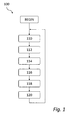
- a method 100 for closed-loop supply of liquid metal in accordance with a currently preferred embodiment of the invention, will now be described with reference to figure 1 .
- the method will be described in terms of 'steps'. It is emphasized that 'steps' are not necessarily processes that are delimited in time or separate from each other, and more than one 'step' may be performed at the same time in a parallel fashion.
- the intended outlook of this disclosure is that the 'steps' represent the different treatments that a liquid undergoes during its loop through a circulation system adapted to perform the method.
- step 110 the pressure of the liquid metal is raised to a high pressure.
- the high pressure should be sufficient in order for the liquid metal jet to obtain a high propagation speed in the vacuum chamber once injected from the nozzle.
- the high pressure will be at least 10 bar, preferably at least 50 bar and up to more than 100 bar.
- the liquid metal that is being pressurized is accommodated in a closed-loop circulation system 300 comprising a high-pressure pump 312, preferably a diaphragm pump or other high-pressure pump.
- the pump constitutes a transition to a first portion 310 (high pressure portion) of the circulation system 300.
- step 112 the pressurized liquid metal is conducted through the high pressure portion 310 of the system 300 towards a nozzle 332.
- the high pressure portion 310 of the circulation system is located between the high-pressure pump 312 and the nozzle 332.
- the pressurized liquid metal will lose some pressure during its transportation from the pump 312 to the nozzle 332 in step 112, but the pressure is kept sufficiently high in order for the metal to reach the nozzle at a sufficiently high pressure of at least 10 bar, and typically at least 50 bar.
- the pressurized liquid metal is passed through an optional fine filter 316 before it reaches the nozzle 332.
- the fine filter 316 may be provided in the form of a stainless-steel sieve or several consecutive sieves.
- pressure pulses propagating in the pressurized liquid metal may occur as a side effect of the pressurization.
- Such pressure pulses may be damped in an optional third step 114 using a damper 318 provided in the first portion of the system 310, before or after the fine filter 316.
- the damper may comprise a membrane having an amount of gas (such as compressed N 2 ) enclosed behind it.
- the membrane On the arrival of a pressure pulse at the damper 318, the liquid-side pressure increases, the membrane extends and compresses the gas. As the pressure sinks back, the gas expands again to its former volume. In effect, any residual pulse propagating onwards past the damper 318 towards the nozzle 332 has a reduced amplitude.
- a connection line has been drawn from the first portion 310 of the circulation system and the damper 318.
- a damper of a similar kind may be arranged directly, in-line, in the first portion 310 of the system and/or have the form of an enlarged duct segment having as wall a flexible membrane supported by a compressed gas volume, as described above.
- multiple dampers may be provided in the first portion 310.
- step 116 the liquid metal is ejected by the nozzle 332 into a vacuum chamber 330.
- the steady (spatially continuous) liquid-metal jet may then be used as a target for an electron beam (not shown) in this chamber 330.
- the electron beam impacts the liquid metal in an interaction region (not shown), and part of the electron beam energy is converted into X-rays.
- the nozzle orifice to be used has such shape and dimensions that the ejected liquid metal assumes the form of a physically continuous jet. The jet will tend to relax into a state of lower surface energy and thereby typically change its shape.
- the nozzle is a sapphire plate or ruby plate, through which a cylindrical or conical hole has been provided.
- the diameter of the hole may be of the same order as the thickness of the plate.
- the shape of the nozzle should minimize production of liquid-metal mist, which may contaminate the vacuum chamber 330.
- the desired cross-section of the jet may be taken as a starting point in dimensioning the nozzle.
- the pressure of the liquid metal at the nozzle is about 100 bar.
- the nozzle has an ejection orifice that is 100 ⁇ m in diameter, which is similar to the wall thickness of the sapphire nozzle.
- a suitable electron beam for impact upon the liquid metal jet has a focus of about 20 ⁇ m diameter, and a power of about 200 W.
- the ejected liquid metal is collected in a collection reservoir 334.
- the liquid metal may need to be cooled in order to avoid overheating of the system.
- the temperature of the liquid metal in the reservoir should preferably be maintained at a temperature slightly above the melting temperature, and may vary as a function of the melting point of the metal, the kind of metal used, the thermal insulation of the system 300 and the heat resistance of its components. Cooling may be effected by a heat-conducting circuit 336 which expels the excess heat H outside the system. If the heat conduction between the reservoir 334 and the outside of the system is large, a passive heat-conducting circuit may provide sufficient cooling. If more powerful cooling is required, one may use active refrigeration including compression of a cooling medium. In a preferred embodiment, the cooling is effected using water-cooled aluminum blocks which are clamped to the reservoir and/or the conduits.
- the collection of the liquid-metal jet produces as little debris as possible. It has been found that the collection of the liquid metal progresses in a regular, non-chaotic and not very splashing fashion if the jet is conducted into the collection reservoir 334 via a slanting surface.
- the slanting surface may be an inner wall of the reservoir 334 or a plate arranged in proximity of the liquid-metal surface during steady-state operation of the circulation system 300. Best debris-preventing results have been achieved using a slanting surface at 45 degrees or less with respect to the metal jet. The slanting surface may be as steep as 10 degrees or even less.
- the liquid-metal surface may be covered by a screen comprising an entry aperture for the jet; such screen is adapted to capture mist and splashes and prevent these from contaminating the vacuum chamber 330.
- the pressure of the collected liquid metal is raised to an inlet pressure for the high-pressure pump.
- This step takes place in a second portion 320 of the system 300 located between the collection reservoir 334 and the suction side of the high-pressure pump 312.
- the pressure rise is effected actively by means of a primer pump 322.
- the inlet pressure to the high-pressure pump should be at least 0.1 bar, preferably at least 0.2 bar.
- a coarse mechanical filter 324 such as a stainless-steel filter, may optionally be provided upstream of the primer pump 322 to protect it from potentially harmful solid contaminants.
- a preferred metal for use in the method above is an alloy comprising 95 wt% of Ga and 5 wt% of In, having a melting point of 25°C and a freezing point of about 16°C.
- Other conceivable metals for use in the method are Galinstan TM , which is an alloy comprising 68.5 wt% Ga, 21.5 wt% In and 10 wt% Sn, having a melting and freezing point of about -19°C; an alloy comprising 66 wt% In and 34 wt% Bi, having a melting and freezing point of about 72°C; and pure In having a melting and freezing point of about 157°C.
- FIG. 3 An apparatus according to the present invention in the form of a closed-loop circulation system 300 for liquid metal is schematically shown in figure 3 as a block diagram.
- the apparatus comprises a vacuum chamber 330 in which an electron beam (not shown) is to impact upon the liquid metal target jet in order to produce X-ray radiation by bremsstrahlung and characteristic line emission.
- a nozzle 332 is provided at the vacuum chamber for generating the liquid metal target jet.
- the nozzle is operatively connected to a high-pressure pump 312 through a pipe or conduit system.
- the portion 310 of the closed-loop circulation system between the nozzle and the high-pressure pump constitutes a high pressure portion (first portion) in which pressurized liquid metal is transported towards the nozzle 332 in order to be ejected as the liquid metal target jet.
- the high pressure portion 310 of the circulation system there may optionally be provided a damper 318.
- the purpose of such damper 318 is to reduce any pressure pulses in the pipe system caused by the high-pressure pump 312, in order for the generation of the liquid metal target jet at the nozzle 332 to be smooth and continuous.
- the high pressure portion 310 of the circulation system may comprise a filter, such as the fine filter indicated at 316, for removing any fine particles that may otherwise clog or hamper the nozzle 332.
- the high-pressure pump 312 works from a second portion 320 of the closed-loop circulation system, in which the pressure of the liquid metal is considerably lower than in the high pressure portion 310.
- the pressure of the liquid metal should have a suitable inlet pressure.
- a primer pump 322 is provided in the second portion of the circulation system for raising the pressure of the liquid metal from the low pressure present at the vacuum chamber to a suitable inlet pressure.
- the inlet pressure at the inlet side of the high-pressure pump is at least 0.1 bar, more preferably at least 0.2 bar.
- the second portion of the pipe system 320 connects the high-pressure pump 312 to a collection reservoir 334.
- the liquid metal is collected in the collection reservoir 332 for further recirculation, and the primer pump 322 raises the pressure to a suitable inlet pressure for the high-pressure pump 312.
- the primer pump 322 can be dispensed with if other means for raising the pressure to a suitable inlet pressure for the high-pressure pump is provided.
- a sufficient inlet pressure for the high-pressure pump can be obtained by arranging the high-pressure pump at such position that a column of liquid metal is present above the pump.
- the high-pressure pump is located lower in the gravitational field than the collection reservoir and the hydrostatic pressure caused by the column of liquid metal provides a sufficient inlet pressure.
- An optional filter such as a coarse filter 324, may be provided in the fluid path of the liquid metal between the collection reservoir 334 and the high-pressure pump 312 for removing particulate contamination in the liquid metal.
- a cooling system 336 may be provided in connection with the collection reservoir.
- the cooling system comprises one or more water cooled blocks clamped to the pipe system close to the collection reservoir.
- the water cooled blocks can be aluminum blocks having channels for the cooling water.
- the temperature control of the metal within the closed-loop circulation system is preferably such that the temperature of the metal is maintained slightly above the melting point for the metal at issue.
- the temperature of the metal immediately after having its interaction with the electron beam will be considerably higher until the cooling in connection with the collection reservoir has had its effect.
- the temperature of the metal is best kept moderate.
- One reason for keeping the metal temperature at moderate levels is that the metal may become aggressive to the piping material and other parts of the system at high temperatures.
- some metals used in connection with the present invention may require that heat is supplied at some portions in order to maintain the metal liquid at all times during operation of the system. This may, for example, mean that a heater can be added at the high-pressure portion of the circulation system. Moreover, supply of heat is often required during start-up of the system when the metal used is not liquid at ambient (room) temperatures.
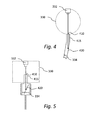
- FIGS 4 and 5 are two examples of how the liquid metal collection could be effected. It should be noted that figures 4 and 5 are highly schematic and only illustrate the general principles. In figures 4 and 5 , the liquid metal jet is schematically indicated by the downwards-pointing arrows.
- the slanting surface as well as the collection reservoir is part of the pipe system, as schematically shown in figure 4 .
- the outlet from the vacuum chamber is designed such that the liquid metal jet exits the vacuum chamber through an opening 410, continues some distance through a straight portion of an exit pipe 415, and eventually hits a slanting portion 420 of the piping.
- the exit opening 410 from the vacuum chamber may be provided with an aperture in order to reduce the physical opening between the vacuum chamber and the piping.
- the collection reservoir 334 is in this case constituted by the lower part of the exit pipe from the vacuum chamber, as indicated in figure 4 .
- the straight portion 415 of the piping may be located within the general region of the vacuum chamber, as schematically shown in figure 5 .
- the collection reservoir has the form of a container. If the piping itself or the container lacks a natural slanting surface for the liquid metal jet to hit after its passage through the vacuum chamber, the slanting surface may be provided in the form of a plate or a cone or similar, which is also schematically shown in figure 5 .
- the present invention also relates to an X-ray source which comprises a closed-loop circulation system for liquid metal according to the above.
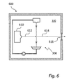
- X-ray source is schematically shown in figure 6 .
- the X-ray source 600 comprises, in addition to the closed-loop liquid metal circulation system 300, an electron source 610 for generating an electron beam 612.
- the electron beam is to interact with the liquid metal jet to generate, preferably by bremsstrahlung and characteristic line emission, X-ray radiation.
- the generated X-ray radiation propagates as indicated by the arrow 614 towards an X-ray window 616, through which the X-ray radiation exits the vacuum chamber 330.
- the vacuum chamber is shown to enclose both the circulation system 300 and the electron beam source 610. However, it may be preferred to have e.g. circulation pumps and some of the piping for the liquid metal outside the vacuum chamber.
- the electron source 610 is only shown very schematically, and will in any implementation normally have some parts located outside of the vacuum chamber.
- a method (100) for closed-loop supply of liquid metal to an interaction region, in which an electron beam is to impact upon the liquid metal to generate X rays comprising the steps of:
Landscapes
- Physics & Mathematics (AREA)
- Engineering & Computer Science (AREA)
- Plasma & Fusion (AREA)
- General Physics & Mathematics (AREA)
- X-Ray Techniques (AREA)
- Optics & Photonics (AREA)
- Particle Accelerators (AREA)
Claims (15)
- Verfahren (100) zur Zufuhr von Flüssigmetall in einem geschlossenen Kreis zu einem Interaktionsbereich, in dem ein Elektronenstrahl auf das Flüssigmetall treffen soll, um Röntgenstrahlen zu erzeugen, umfassend die folgenden Schritte:Erhöhen (110) eines Drucks des Flüssigmetalls in einem ersten Abschnitt (210; 310) eines geschlossenen Umlaufsystems auf wenigstens 10 bar unter Verwendung einer Hochdruckpumpe (212; 312);Leiten (112) des Flüssigmetalls bei einem Druck von wenigstens 10 bar zu einer Düse (232; 332);Ausstoßen (116) des Flüssigmetalls aus der Düse in eine Vakuumkammer (230; 330), in der sich der Interaktionsbereich befindet, um einen Flüssigmetallstrahl zu erzeugen, der sich mit 10 m/s oder mehr durch die Vakuumkammer ausbreitet;Auffangen (118) des ausgestoßenen Flüssigmetalls in einem Auffangbehälter (234; 334),Erhöhen (120) eines Drucks des aufgefangenen Flüssigmetalls auf einen Einlassdruck, der für die Hochdruckpumpe geeignet ist, wobei der Einlassdruck wenigstens 0,1 bar beträgt; undWiederholen der vorstehenden Schritte, um die Zufuhr von Flüssigmetall zum Interaktionsbereich in einem geschlossenen Kreis zu bewirken,dadurch gekennzeichnet, dass ein Auffangbehälter mit einer Öffnung (410) und einer Schrägfläche (420), auf die der Metallstrahl trifft, verwendet wird, um das ausgestoßene Flüssigmetall aufzufangen, um die Verschmutzung der Vakuumkammer durch Flüssigmetallspritzer, Nebel und dergleichen aus dem Auffangbehälter zu verringern, und dassdas Flüssigmetall auf seinem Weg von dem Auffangbehälter zur Hochdruckpumpe und/oder auf seinem Weg von der Hochdruckpumpe zur Düse durch wenigstens einen Filter (316, 324) geführt wird.
- Verfahren nach Anspruch 1, wobei der Schritt des Erhöhens des Drucks des aufgefangenen Flüssigmetalls auf den Einlassdruck das Anordnen der Hochdruckpumpe in dem Gravitationsfeld niedriger als den Behälter umfasst.
- Verfahren nach Anspruch 1 oder 2, wobei der Schritt des Erhöhens des Drucks des aufgefangenen Flüssigmetalls auf den Einlassdruck die Verwendung einer Primer-Pumpe (322) umfasst.
- Verfahren nach einem der vorhergehenden Ansprüche, ferner umfassend das Hindurchführen des Flüssigmetalls durch einen Grobfilter (324) auf seinem Weg von dem Auffangbehälter zur Hochdruckpumpe.
- Verfahren nach einem der vorhergehenden Ansprüche, ferner umfassend das Hindurchführen des Flüssigmetalls durch einen Feinfilter (316) auf seinem Weg von der Hochdruckpumpe zur Düse.
- Verfahren nach einem der vorhergehenden Ansprüche, wobei der Schritt des Erhöhens des Drucks unter Verwendung der Hochdruckpumpe das Erhöhen des Drucks auf wenigstens 50 bar, wie zum Beispiel wenigstens 100 bar, umfasst.
- Verfahren nach einem der vorhergehenden Ansprüche, wobei der Flüssigmetallstrahl während seiner Ausbreitung durch die Vakuumkammer von der Düse bis zu einer Stelle, an der der Elektronenstrahl auf den Flüssigmetallstrahl treffen soll, räumlich durchgehend ist.
- Verfahren nach einem der vorhergehenden Ansprüche, wobei das aufgefangene Flüssigmetall gekühlt wird, vorzugsweise auf eine Temperatur unterhalb von 150 °C, um überschüssige Wärme abzuführen, die durch die Interaktion zwischen dem Elektronenstrahl und dem Flüssigmetallstrahl erzeugt wurde.
- Geschlossenes Umlaufsystem (200; 300) zur Zufuhr von Flüssigmetall zu einem Interaktionsbereich, in welchem ein Elektronenstrahl auf das Flüssigmetall treffen soll, um Röntgenstrahlen zu erzeugen, umfassend:eine Hochdruckpumpe (212; 312), die mit einer ersten Seite eines Hochdruckabschnitts (210; 310) des Umlaufsystems verbunden ist;eine Düse (232; 332), die mit einer zweiten Seite des Hochdruckabschnitts (210; 310) des Umlaufsystems verbunden ist;eine Vakuumkammer (230; 330) zum Aufnehmen von Flüssigmetall, das in Form eines Strahls aus der Düse ausgestoßen wird, wobei sich der Strahl mit 10 m/s oder mehr durch die Vakuumkammer ausbreitet;einen Auffangbehälter (234; 334) zum Auffangen des Flüssigmetalls nach dem Durchgang durch die Vakuumkammer; undeine Einrichtung, die sich in der Flussrichtung des Flüssigmetalls zwischen der Vakuumkammer und der Hochdruckpumpe befindet, um einen Druck des Flüssigmetalls auf wenigstens 0,1 bar zu erhöhen, um einen Einlassdruck für die Hochdruckpumpe bereitzustellen,wobei der Druck des Flüssigmetalls in dem Hochdruckabschnitt des Umlaufsystems wenigstens 10 bar beträgt,dadurch gekennzeichnet, dass der Auffangbehälter mit einer Öffnung (410) und einer Schrägfläche (420) versehen ist, auf die der Metallstrahl trifft, um die Verschmutzung der Vakuumkammer durch Flüssigmetallspritzer, Nebel und dergleichen aus dem Auffangbehälter zu verringern, und dass das System wenigstens einen Filter (316, 324) zum Entfernen einer partikulären Verschmutzung durch das umlaufende Flüssigmetall umfasst.
- Umlaufsystem nach Anspruch 9, wobei die Einrichtung zum Erhöhen des Drucks des Flüssigmetalls auf wenigstens 0,1 bar die Form einer Flüssigkeitssäule über der Hochdruckpumpe hat, die sich in dem Gravitationsfeld niedriger befindet als der Auffangbehälter.
- Umlaufsystem nach Anspruch 9, wobei die Einrichtung zum Erhöhen des Drucks des Flüssigmetalls auf wenigstens 0,1 bar die Form einer Primer-Pumpe (322) hat.
- Umlaufsystem nach einem der Ansprüche 9 bis 11, wobei ein Feinfilter (316) in der Flussrichtung des Flüssigmetalls zwischen der Hochdruckpumpe und der Düse angeordnet ist.
- Umlaufsystem nach einem der Ansprüche 9 bis 12, wobei ein Grobfilter (324) in der Flussrichtung des Flüssigmetalls zwischen dem Auffangbehälter und der Hochdruckpumpe angeordnet ist.
- Umlaufsystem nach einem der Ansprüche 9 bis 13, wobei die Öffnung des Auffangbehälters eine Öffnung in einer Austrittsöffnung aus der Vakuumkammer ist, wobei die Öffnung dafür ausgelegt und strukturiert ist, die Gefahr von Fremdkörpern, die aus dem Auffangbehälter in die Vakuumkammer eintreten, zu verringern.
- Röntgenstrahlquelle (600), umfassend eine Elektronenquelle (610) und ein geschlossenes Umlaufsystem nach einem der Ansprüche 9 bis 14.
Priority Applications (1)
| Application Number | Priority Date | Filing Date | Title |
|---|---|---|---|
| EP14158592.7A EP2743963B8 (de) | 2009-04-03 | 2009-04-03 | Bereitstellung eines Flüssigmetall-Targets bei der Röntgenstrahlerzeugung |
Applications Claiming Priority (3)
| Application Number | Priority Date | Filing Date | Title |
|---|---|---|---|
| EP09776509A EP2415065A1 (de) | 2009-04-03 | 2009-04-03 | Zuführung eines flüssigmetallziels bei der erzeugung von röntgenstrahlen |
| PCT/EP2009/002464 WO2010112048A1 (en) | 2009-04-03 | 2009-04-03 | Supply of a liquid-metal target in x-ray generation |
| EP14158592.7A EP2743963B8 (de) | 2009-04-03 | 2009-04-03 | Bereitstellung eines Flüssigmetall-Targets bei der Röntgenstrahlerzeugung |
Related Parent Applications (1)
| Application Number | Title | Priority Date | Filing Date |
|---|---|---|---|
| EP09776509A Division EP2415065A1 (de) | 2009-04-03 | 2009-04-03 | Zuführung eines flüssigmetallziels bei der erzeugung von röntgenstrahlen |
Publications (4)
| Publication Number | Publication Date |
|---|---|
| EP2743963A2 EP2743963A2 (de) | 2014-06-18 |
| EP2743963A3 EP2743963A3 (de) | 2014-07-30 |
| EP2743963B1 true EP2743963B1 (de) | 2015-09-23 |
| EP2743963B8 EP2743963B8 (de) | 2015-10-28 |
Family
ID=41302843
Family Applications (2)
| Application Number | Title | Priority Date | Filing Date |
|---|---|---|---|
| EP14158592.7A Active EP2743963B8 (de) | 2009-04-03 | 2009-04-03 | Bereitstellung eines Flüssigmetall-Targets bei der Röntgenstrahlerzeugung |
| EP09776509A Withdrawn EP2415065A1 (de) | 2009-04-03 | 2009-04-03 | Zuführung eines flüssigmetallziels bei der erzeugung von röntgenstrahlen |
Family Applications After (1)
| Application Number | Title | Priority Date | Filing Date |
|---|---|---|---|
| EP09776509A Withdrawn EP2415065A1 (de) | 2009-04-03 | 2009-04-03 | Zuführung eines flüssigmetallziels bei der erzeugung von röntgenstrahlen |
Country Status (4)
| Country | Link |
|---|---|
| US (2) | US8837679B2 (de) |
| EP (2) | EP2743963B8 (de) |
| CN (1) | CN102369587B (de) |
| WO (1) | WO2010112048A1 (de) |
Families Citing this family (26)
| Publication number | Priority date | Publication date | Assignee | Title |
|---|---|---|---|---|
| EP3089192B1 (de) | 2010-12-22 | 2018-05-09 | Excillum AB | Fokussierung eines elektronenstrahls in einer röntgenquelle |
| CN103733735B (zh) * | 2011-08-12 | 2016-05-11 | Asml荷兰有限公司 | 辐射源 |
| US8890099B2 (en) | 2011-09-02 | 2014-11-18 | Asml Netherlands B.V. | Radiation source and method for lithographic apparatus for device manufacture |
| US10801975B2 (en) | 2012-05-08 | 2020-10-13 | Kla-Tencor Corporation | Metrology tool with combined X-ray and optical scatterometers |
| WO2013185829A1 (en) | 2012-06-14 | 2013-12-19 | Excillum Ab | Limiting migration of target material |
| EP2837016B1 (de) * | 2012-06-15 | 2016-08-17 | Siemens Aktiengesellschaft | Röntgenstrahlungsquelle und deren verwendung und verfahren zum erzeugen von röntgenstrahlung |
| US9392678B2 (en) | 2012-10-16 | 2016-07-12 | Asml Netherlands B.V. | Target material supply apparatus for an extreme ultraviolet light source |
| DE102013103668B4 (de) | 2013-04-11 | 2016-02-25 | Ushio Denki Kabushiki Kaisha | Anordnung zum Handhaben eines flüssigen Metalls zur Kühlung von umlaufenden Komponenten einer Strahlungsquelle auf Basis eines strahlungsemittierenden Plasmas |
| DE102013209447A1 (de) * | 2013-05-22 | 2014-11-27 | Siemens Aktiengesellschaft | Röntgenquelle und Verfahren zur Erzeugung von Röntgenstrahlung |
| JP6360489B2 (ja) * | 2013-10-28 | 2018-07-18 | ギガフォトン株式会社 | 極端紫外光生成装置 |
| WO2015097888A1 (ja) | 2013-12-27 | 2015-07-02 | ギガフォトン株式会社 | 極端紫外光生成装置 |
| DE102014006063A1 (de) * | 2014-04-25 | 2015-10-29 | Microliquids GmbH | Strahlerzeugungsvorrichtung und Verfahren zur Erzeugung eines Flüssigkeitsstrahls |
| EP3170194B1 (de) * | 2014-07-17 | 2019-05-22 | Siemens Healthcare GmbH | Fluidinjektor für röntgenröhren und verfahren zur bereitstellung einer flüssigkeitsanode durch flüssigmetallinjektion |
| US9544983B2 (en) * | 2014-11-05 | 2017-01-10 | Asml Netherlands B.V. | Apparatus for and method of supplying target material |
| DE102014226813A1 (de) * | 2014-12-22 | 2016-06-23 | Siemens Aktiengesellschaft | Metallstrahlröntgenröhre |
| CN105263251B (zh) * | 2015-10-13 | 2018-02-27 | 上海联影医疗科技有限公司 | 靶组件以及包括该靶组件的直线加速器 |
| EP3416180A1 (de) * | 2017-06-18 | 2018-12-19 | Excillum AB | Röntgenstrahlenquelle mit temperatursteuergerät |
| US10748736B2 (en) * | 2017-10-18 | 2020-08-18 | Kla-Tencor Corporation | Liquid metal rotating anode X-ray source for semiconductor metrology |
| EP3493239A1 (de) * | 2017-12-01 | 2019-06-05 | Excillum AB | Röntgenquelle und verfahren zum erzeugen von röntgenstrahlung |
| EP3525556A1 (de) * | 2018-02-09 | 2019-08-14 | Excillum AB | Verfahren zum schutz einer röntgenquelle und röntgenquelle |
| US10955752B2 (en) | 2018-06-28 | 2021-03-23 | Taiwan Semiconductor Manufacturing Co., Ltd. | EUV radiation source apparatus for lithography |
| EP3736444A1 (de) * | 2019-05-09 | 2020-11-11 | Excillum AB | Elektromagnetische pumpe |
| US11170965B2 (en) | 2020-01-14 | 2021-11-09 | King Fahd University Of Petroleum And Minerals | System for generating X-ray beams from a liquid target |
| EP4075474A1 (de) * | 2021-04-15 | 2022-10-19 | Excillum AB | Röntgenquelle mit flüssigkeitsstrahl-target |
| EP4102070A1 (de) * | 2021-06-11 | 2022-12-14 | Excillum AB | Elektromagnetische pumpe |
| EP4380021A1 (de) * | 2022-12-01 | 2024-06-05 | Excillum AB | Stromgeschützte elektromagnetische pumpenanordnung und verfahren |
Family Cites Families (8)
| Publication number | Priority date | Publication date | Assignee | Title |
|---|---|---|---|---|
| US4953191A (en) | 1989-07-24 | 1990-08-28 | The United States Of America As Represented By The United States Department Of Energy | High intensity x-ray source using liquid gallium target |
| JPH10221499A (ja) * | 1997-02-07 | 1998-08-21 | Hitachi Ltd | レーザプラズマx線源およびそれを用いた半導体露光装置並びに半導体露光方法 |
| EP1305984B1 (de) * | 2000-07-28 | 2010-11-24 | Jettec AB | Verfahren und vorrichtung zur erzeugung von röntgenstrahlung |
| US6711233B2 (en) * | 2000-07-28 | 2004-03-23 | Jettec Ab | Method and apparatus for generating X-ray or EUV radiation |
| US20070269341A1 (en) * | 2006-05-22 | 2007-11-22 | 3M Innovative Properties Company | Sampling assembly and method of preparing samples |
| WO2008042444A2 (en) * | 2006-10-07 | 2008-04-10 | Tbw Industries | Vacuum line clean-out separator system |
| US20080121379A1 (en) * | 2006-11-28 | 2008-05-29 | Otv Sa S.A. | Evaporator |
| US9052522B2 (en) * | 2010-06-03 | 2015-06-09 | Alessi Technologies, Llc | System and method for mounting a specimen on a slide |
-
2009
- 2009-04-03 EP EP14158592.7A patent/EP2743963B8/de active Active
- 2009-04-03 CN CN200980158566.4A patent/CN102369587B/zh active Active
- 2009-04-03 WO PCT/EP2009/002464 patent/WO2010112048A1/en not_active Ceased
- 2009-04-03 US US13/262,499 patent/US8837679B2/en active Active
- 2009-04-03 EP EP09776509A patent/EP2415065A1/de not_active Withdrawn
-
2014
- 2014-08-12 US US14/457,385 patent/US9530607B2/en active Active
Also Published As
| Publication number | Publication date |
|---|---|
| US20140348302A1 (en) | 2014-11-27 |
| WO2010112048A1 (en) | 2010-10-07 |
| US8837679B2 (en) | 2014-09-16 |
| US9530607B2 (en) | 2016-12-27 |
| CN102369587B (zh) | 2015-02-11 |
| EP2415065A1 (de) | 2012-02-08 |
| CN102369587A (zh) | 2012-03-07 |
| US20120057680A1 (en) | 2012-03-08 |
| EP2743963A3 (de) | 2014-07-30 |
| EP2743963B8 (de) | 2015-10-28 |
| EP2743963A2 (de) | 2014-06-18 |
Similar Documents
| Publication | Publication Date | Title |
|---|---|---|
| US9530607B2 (en) | Supply of a liquid-metal target in X-ray generation | |
| US8138487B2 (en) | System, method and apparatus for droplet catcher for prevention of backsplash in a EUV generation chamber | |
| EP1367441B1 (de) | Gasdynamisch-kontrollierte Tröpfchen als Target für eine Laser-Plasma Strahlungsquelle im extrem-ultravioletten Bereich | |
| US7368742B2 (en) | Arrangement and method for metering target material for the generation of short-wavelength electromagnetic radiation | |
| KR102539861B1 (ko) | 초음파 원자화 방법에 의한 구형 금속 파우더들의 제조를 위한 장치 | |
| US7122816B2 (en) | Method and apparatus for EUV light source target material handling | |
| WO2001031678A1 (en) | Method and radiation generating system using microtargets | |
| US11869742B2 (en) | X-ray source with rotating liquid-metal target | |
| JP2019012293A (ja) | レーザ生成プラズマeuv光源におけるソース材料送出の装置及び方法 | |
| EP1854121B1 (de) | Verfahren und vorrichtung zur euv-lichtquellen-zielmaterial-handhabung | |
| US20190200442A1 (en) | Apparatus for and method of source material delivery in a laser produced plasma euv light source | |
| CN104681378B (zh) | 在x射线产生中液体金属靶的供应 | |
| EP3424068B1 (de) | Flüssig-target-röntgenquelle mit strahlmischwerkzeug | |
| CN218730786U (zh) | 一种用于x射线源阳极靶的液态金属射流系统 | |
| US20250021026A1 (en) | Apparatus for supplying liquid target material to a radiation source | |
| EP3416180A1 (de) | Röntgenstrahlenquelle mit temperatursteuergerät | |
| CN118303134A (zh) | 用于将液体目标材料供应至辐射源的设备 |
Legal Events
| Date | Code | Title | Description |
|---|---|---|---|
| PUAI | Public reference made under article 153(3) epc to a published international application that has entered the european phase |
Free format text: ORIGINAL CODE: 0009012 |
|
| 17P | Request for examination filed |
Effective date: 20140310 |
|
| AC | Divisional application: reference to earlier application |
Ref document number: 2415065 Country of ref document: EP Kind code of ref document: P |
|
| AK | Designated contracting states |
Kind code of ref document: A2 Designated state(s): AT BE BG CH CY CZ DE DK EE ES FI FR GB GR HR HU IE IS IT LI LT LU LV MC MK MT NL NO PL PT RO SE SI SK TR |
|
| PUAL | Search report despatched |
Free format text: ORIGINAL CODE: 0009013 |
|
| AK | Designated contracting states |
Kind code of ref document: A3 Designated state(s): AT BE BG CH CY CZ DE DK EE ES FI FR GB GR HR HU IE IS IT LI LT LU LV MC MK MT NL NO PL PT RO SE SI SK TR |
|
| RIC1 | Information provided on ipc code assigned before grant |
Ipc: H01J 35/08 20060101AFI20140620BHEP |
|
| RBV | Designated contracting states (corrected) |
Designated state(s): AT BE BG CH CY CZ DE DK EE ES FI FR GB GR HR HU IE IS IT LI LT LU LV MC MK MT NL NO PL PT RO SE SI SK TR |
|
| R17P | Request for examination filed (corrected) |
Effective date: 20140707 |
|
| GRAP | Despatch of communication of intention to grant a patent |
Free format text: ORIGINAL CODE: EPIDOSNIGR1 |
|
| INTG | Intention to grant announced |
Effective date: 20150417 |
|
| GRAS | Grant fee paid |
Free format text: ORIGINAL CODE: EPIDOSNIGR3 |
|
| GRAA | (expected) grant |
Free format text: ORIGINAL CODE: 0009210 |
|
| AC | Divisional application: reference to earlier application |
Ref document number: 2415065 Country of ref document: EP Kind code of ref document: P |
|
| AK | Designated contracting states |
Kind code of ref document: B1 Designated state(s): AT BE BG CH CY CZ DE DK EE ES FI FR GB GR HR HU IE IS IT LI LT LU LV MC MK MT NL NO PL PT RO SE SI SK TR |
|
| REG | Reference to a national code |
Ref country code: GB Ref legal event code: FG4D |
|
| REG | Reference to a national code |
Ref country code: CH Ref legal event code: EP |
|
| REG | Reference to a national code |
Ref country code: AT Ref legal event code: REF Ref document number: 751625 Country of ref document: AT Kind code of ref document: T Effective date: 20151015 |
|
| REG | Reference to a national code |
Ref country code: IE Ref legal event code: FG4D |
|
| RAP2 | Party data changed (patent owner data changed or rights of a patent transferred) |
Owner name: EXCILLUM AB |
|
| REG | Reference to a national code |
Ref country code: DE Ref legal event code: R096 Ref document number: 602009033876 Country of ref document: DE |
|
| PG25 | Lapsed in a contracting state [announced via postgrant information from national office to epo] |
Ref country code: GR Free format text: LAPSE BECAUSE OF FAILURE TO SUBMIT A TRANSLATION OF THE DESCRIPTION OR TO PAY THE FEE WITHIN THE PRESCRIBED TIME-LIMIT Effective date: 20151224 Ref country code: LT Free format text: LAPSE BECAUSE OF FAILURE TO SUBMIT A TRANSLATION OF THE DESCRIPTION OR TO PAY THE FEE WITHIN THE PRESCRIBED TIME-LIMIT Effective date: 20150923 Ref country code: NO Free format text: LAPSE BECAUSE OF FAILURE TO SUBMIT A TRANSLATION OF THE DESCRIPTION OR TO PAY THE FEE WITHIN THE PRESCRIBED TIME-LIMIT Effective date: 20151223 Ref country code: FI Free format text: LAPSE BECAUSE OF FAILURE TO SUBMIT A TRANSLATION OF THE DESCRIPTION OR TO PAY THE FEE WITHIN THE PRESCRIBED TIME-LIMIT Effective date: 20150923 Ref country code: LV Free format text: LAPSE BECAUSE OF FAILURE TO SUBMIT A TRANSLATION OF THE DESCRIPTION OR TO PAY THE FEE WITHIN THE PRESCRIBED TIME-LIMIT Effective date: 20150923 |
|
| REG | Reference to a national code |
Ref country code: LT Ref legal event code: MG4D |
|
| REG | Reference to a national code |
Ref country code: AT Ref legal event code: MK05 Ref document number: 751625 Country of ref document: AT Kind code of ref document: T Effective date: 20150923 |
|
| REG | Reference to a national code |
Ref country code: NL Ref legal event code: FP |
|
| PG25 | Lapsed in a contracting state [announced via postgrant information from national office to epo] |
Ref country code: HR Free format text: LAPSE BECAUSE OF FAILURE TO SUBMIT A TRANSLATION OF THE DESCRIPTION OR TO PAY THE FEE WITHIN THE PRESCRIBED TIME-LIMIT Effective date: 20150923 Ref country code: SE Free format text: LAPSE BECAUSE OF FAILURE TO SUBMIT A TRANSLATION OF THE DESCRIPTION OR TO PAY THE FEE WITHIN THE PRESCRIBED TIME-LIMIT Effective date: 20150923 |
|
| REG | Reference to a national code |
Ref country code: FR Ref legal event code: PLFP Year of fee payment: 8 |
|
| PG25 | Lapsed in a contracting state [announced via postgrant information from national office to epo] |
Ref country code: IT Free format text: LAPSE BECAUSE OF FAILURE TO SUBMIT A TRANSLATION OF THE DESCRIPTION OR TO PAY THE FEE WITHIN THE PRESCRIBED TIME-LIMIT Effective date: 20150923 Ref country code: SK Free format text: LAPSE BECAUSE OF FAILURE TO SUBMIT A TRANSLATION OF THE DESCRIPTION OR TO PAY THE FEE WITHIN THE PRESCRIBED TIME-LIMIT Effective date: 20150923 Ref country code: ES Free format text: LAPSE BECAUSE OF FAILURE TO SUBMIT A TRANSLATION OF THE DESCRIPTION OR TO PAY THE FEE WITHIN THE PRESCRIBED TIME-LIMIT Effective date: 20150923 Ref country code: IS Free format text: LAPSE BECAUSE OF FAILURE TO SUBMIT A TRANSLATION OF THE DESCRIPTION OR TO PAY THE FEE WITHIN THE PRESCRIBED TIME-LIMIT Effective date: 20160123 Ref country code: CZ Free format text: LAPSE BECAUSE OF FAILURE TO SUBMIT A TRANSLATION OF THE DESCRIPTION OR TO PAY THE FEE WITHIN THE PRESCRIBED TIME-LIMIT Effective date: 20150923 Ref country code: EE Free format text: LAPSE BECAUSE OF FAILURE TO SUBMIT A TRANSLATION OF THE DESCRIPTION OR TO PAY THE FEE WITHIN THE PRESCRIBED TIME-LIMIT Effective date: 20150923 |
|
| PG25 | Lapsed in a contracting state [announced via postgrant information from national office to epo] |
Ref country code: PT Free format text: LAPSE BECAUSE OF FAILURE TO SUBMIT A TRANSLATION OF THE DESCRIPTION OR TO PAY THE FEE WITHIN THE PRESCRIBED TIME-LIMIT Effective date: 20160125 Ref country code: PL Free format text: LAPSE BECAUSE OF FAILURE TO SUBMIT A TRANSLATION OF THE DESCRIPTION OR TO PAY THE FEE WITHIN THE PRESCRIBED TIME-LIMIT Effective date: 20150923 Ref country code: AT Free format text: LAPSE BECAUSE OF FAILURE TO SUBMIT A TRANSLATION OF THE DESCRIPTION OR TO PAY THE FEE WITHIN THE PRESCRIBED TIME-LIMIT Effective date: 20150923 Ref country code: RO Free format text: LAPSE BECAUSE OF FAILURE TO SUBMIT A TRANSLATION OF THE DESCRIPTION OR TO PAY THE FEE WITHIN THE PRESCRIBED TIME-LIMIT Effective date: 20150923 |
|
| REG | Reference to a national code |
Ref country code: DE Ref legal event code: R097 Ref document number: 602009033876 Country of ref document: DE |
|
| PLBE | No opposition filed within time limit |
Free format text: ORIGINAL CODE: 0009261 |
|
| STAA | Information on the status of an ep patent application or granted ep patent |
Free format text: STATUS: NO OPPOSITION FILED WITHIN TIME LIMIT |
|
| 26N | No opposition filed |
Effective date: 20160624 |
|
| PG25 | Lapsed in a contracting state [announced via postgrant information from national office to epo] |
Ref country code: DK Free format text: LAPSE BECAUSE OF FAILURE TO SUBMIT A TRANSLATION OF THE DESCRIPTION OR TO PAY THE FEE WITHIN THE PRESCRIBED TIME-LIMIT Effective date: 20150923 Ref country code: BE Free format text: LAPSE BECAUSE OF NON-PAYMENT OF DUE FEES Effective date: 20160430 |
|
| PG25 | Lapsed in a contracting state [announced via postgrant information from national office to epo] |
Ref country code: SI Free format text: LAPSE BECAUSE OF FAILURE TO SUBMIT A TRANSLATION OF THE DESCRIPTION OR TO PAY THE FEE WITHIN THE PRESCRIBED TIME-LIMIT Effective date: 20150923 |
|
| REG | Reference to a national code |
Ref country code: CH Ref legal event code: PL |
|
| PG25 | Lapsed in a contracting state [announced via postgrant information from national office to epo] |
Ref country code: BE Free format text: LAPSE BECAUSE OF FAILURE TO SUBMIT A TRANSLATION OF THE DESCRIPTION OR TO PAY THE FEE WITHIN THE PRESCRIBED TIME-LIMIT Effective date: 20150923 Ref country code: LU Free format text: LAPSE BECAUSE OF FAILURE TO SUBMIT A TRANSLATION OF THE DESCRIPTION OR TO PAY THE FEE WITHIN THE PRESCRIBED TIME-LIMIT Effective date: 20160403 |
|
| REG | Reference to a national code |
Ref country code: IE Ref legal event code: MM4A |
|
| PG25 | Lapsed in a contracting state [announced via postgrant information from national office to epo] |
Ref country code: LI Free format text: LAPSE BECAUSE OF NON-PAYMENT OF DUE FEES Effective date: 20160430 Ref country code: CH Free format text: LAPSE BECAUSE OF NON-PAYMENT OF DUE FEES Effective date: 20160430 |
|
| REG | Reference to a national code |
Ref country code: FR Ref legal event code: PLFP Year of fee payment: 9 |
|
| PG25 | Lapsed in a contracting state [announced via postgrant information from national office to epo] |
Ref country code: IE Free format text: LAPSE BECAUSE OF NON-PAYMENT OF DUE FEES Effective date: 20160403 |
|
| REG | Reference to a national code |
Ref country code: FR Ref legal event code: PLFP Year of fee payment: 10 |
|
| PG25 | Lapsed in a contracting state [announced via postgrant information from national office to epo] |
Ref country code: HU Free format text: LAPSE BECAUSE OF FAILURE TO SUBMIT A TRANSLATION OF THE DESCRIPTION OR TO PAY THE FEE WITHIN THE PRESCRIBED TIME-LIMIT; INVALID AB INITIO Effective date: 20090403 |
|
| PG25 | Lapsed in a contracting state [announced via postgrant information from national office to epo] |
Ref country code: MC Free format text: LAPSE BECAUSE OF FAILURE TO SUBMIT A TRANSLATION OF THE DESCRIPTION OR TO PAY THE FEE WITHIN THE PRESCRIBED TIME-LIMIT Effective date: 20150923 Ref country code: MT Free format text: LAPSE BECAUSE OF NON-PAYMENT OF DUE FEES Effective date: 20160430 Ref country code: MK Free format text: LAPSE BECAUSE OF FAILURE TO SUBMIT A TRANSLATION OF THE DESCRIPTION OR TO PAY THE FEE WITHIN THE PRESCRIBED TIME-LIMIT Effective date: 20150923 Ref country code: CY Free format text: LAPSE BECAUSE OF FAILURE TO SUBMIT A TRANSLATION OF THE DESCRIPTION OR TO PAY THE FEE WITHIN THE PRESCRIBED TIME-LIMIT Effective date: 20150923 |
|
| PG25 | Lapsed in a contracting state [announced via postgrant information from national office to epo] |
Ref country code: BG Free format text: LAPSE BECAUSE OF FAILURE TO SUBMIT A TRANSLATION OF THE DESCRIPTION OR TO PAY THE FEE WITHIN THE PRESCRIBED TIME-LIMIT Effective date: 20150923 |
|
| PG25 | Lapsed in a contracting state [announced via postgrant information from national office to epo] |
Ref country code: TR Free format text: LAPSE BECAUSE OF FAILURE TO SUBMIT A TRANSLATION OF THE DESCRIPTION OR TO PAY THE FEE WITHIN THE PRESCRIBED TIME-LIMIT Effective date: 20150923 |
|
| PGFP | Annual fee paid to national office [announced via postgrant information from national office to epo] |
Ref country code: NL Payment date: 20220322 Year of fee payment: 14 |
|
| P01 | Opt-out of the competence of the unified patent court (upc) registered |
Effective date: 20230529 |
|
| REG | Reference to a national code |
Ref country code: NL Ref legal event code: MM Effective date: 20230501 |
|
| PG25 | Lapsed in a contracting state [announced via postgrant information from national office to epo] |
Ref country code: NL Free format text: LAPSE BECAUSE OF NON-PAYMENT OF DUE FEES Effective date: 20230501 |
|
| PGFP | Annual fee paid to national office [announced via postgrant information from national office to epo] |
Ref country code: DE Payment date: 20250318 Year of fee payment: 17 |
|
| PGFP | Annual fee paid to national office [announced via postgrant information from national office to epo] |
Ref country code: GB Payment date: 20260317 Year of fee payment: 18 |
|
| PGFP | Annual fee paid to national office [announced via postgrant information from national office to epo] |
Ref country code: FR Payment date: 20260316 Year of fee payment: 18 |