EP2743750A1 - Optical Adjusting Apparatus - Google Patents
Optical Adjusting Apparatus Download PDFInfo
- Publication number
- EP2743750A1 EP2743750A1 EP13194027.2A EP13194027A EP2743750A1 EP 2743750 A1 EP2743750 A1 EP 2743750A1 EP 13194027 A EP13194027 A EP 13194027A EP 2743750 A1 EP2743750 A1 EP 2743750A1
- Authority
- EP
- European Patent Office
- Prior art keywords
- image stabilization
- magnet
- auto focusing
- disposed
- vcm actuator
- Prior art date
- Legal status (The legal status is an assumption and is not a legal conclusion. Google has not performed a legal analysis and makes no representation as to the accuracy of the status listed.)
- Granted
Links
Images





Classifications
-
- G—PHYSICS
- G02—OPTICS
- G02B—OPTICAL ELEMENTS, SYSTEMS OR APPARATUS
- G02B27/00—Optical systems or apparatus not provided for by any of the groups G02B1/00 - G02B26/00, G02B30/00
- G02B27/64—Imaging systems using optical elements for stabilisation of the lateral and angular position of the image
- G02B27/646—Imaging systems using optical elements for stabilisation of the lateral and angular position of the image compensating for small deviations, e.g. due to vibration or shake
-
- H—ELECTRICITY
- H04—ELECTRIC COMMUNICATION TECHNIQUE
- H04N—PICTORIAL COMMUNICATION, e.g. TELEVISION
- H04N23/00—Cameras or camera modules comprising electronic image sensors; Control thereof
- H04N23/50—Constructional details
- H04N23/55—Optical parts specially adapted for electronic image sensors; Mounting thereof
-
- H—ELECTRICITY
- H04—ELECTRIC COMMUNICATION TECHNIQUE
- H04N—PICTORIAL COMMUNICATION, e.g. TELEVISION
- H04N23/00—Cameras or camera modules comprising electronic image sensors; Control thereof
- H04N23/60—Control of cameras or camera modules
- H04N23/68—Control of cameras or camera modules for stable pick-up of the scene, e.g. compensating for camera body vibrations
-
- G—PHYSICS
- G03—PHOTOGRAPHY; CINEMATOGRAPHY; ANALOGOUS TECHNIQUES USING WAVES OTHER THAN OPTICAL WAVES; ELECTROGRAPHY; HOLOGRAPHY
- G03B—APPARATUS OR ARRANGEMENTS FOR TAKING PHOTOGRAPHS OR FOR PROJECTING OR VIEWING THEM; APPARATUS OR ARRANGEMENTS EMPLOYING ANALOGOUS TECHNIQUES USING WAVES OTHER THAN OPTICAL WAVES; ACCESSORIES THEREFOR
- G03B13/00—Viewfinders; Focusing aids for cameras; Means for focusing for cameras; Autofocus systems for cameras
- G03B13/32—Means for focusing
- G03B13/34—Power focusing
- G03B13/36—Autofocus systems
-
- H—ELECTRICITY
- H02—GENERATION; CONVERSION OR DISTRIBUTION OF ELECTRIC POWER
- H02K—DYNAMO-ELECTRIC MACHINES
- H02K41/00—Propulsion systems in which a rigid body is moved along a path due to dynamo-electric interaction between the body and a magnetic field travelling along the path
- H02K41/02—Linear motors; Sectional motors
- H02K41/035—DC motors; Unipolar motors
- H02K41/0352—Unipolar motors
- H02K41/0354—Lorentz force motors, e.g. voice coil motors
- H02K41/0356—Lorentz force motors, e.g. voice coil motors moving along a straight path
-
- H—ELECTRICITY
- H04—ELECTRIC COMMUNICATION TECHNIQUE
- H04N—PICTORIAL COMMUNICATION, e.g. TELEVISION
- H04N23/00—Cameras or camera modules comprising electronic image sensors; Control thereof
- H04N23/60—Control of cameras or camera modules
- H04N23/68—Control of cameras or camera modules for stable pick-up of the scene, e.g. compensating for camera body vibrations
- H04N23/682—Vibration or motion blur correction
- H04N23/685—Vibration or motion blur correction performed by mechanical compensation
- H04N23/687—Vibration or motion blur correction performed by mechanical compensation by shifting the lens or sensor position
-
- G—PHYSICS
- G02—OPTICS
- G02B—OPTICAL ELEMENTS, SYSTEMS OR APPARATUS
- G02B7/00—Mountings, adjusting means, or light-tight connections, for optical elements
- G02B7/28—Systems for automatic generation of focusing signals
-
- H—ELECTRICITY
- H02—GENERATION; CONVERSION OR DISTRIBUTION OF ELECTRIC POWER
- H02K—DYNAMO-ELECTRIC MACHINES
- H02K2201/00—Specific aspects not provided for in the other groups of this subclass relating to the magnetic circuits
- H02K2201/18—Machines moving with multiple degrees of freedom
-
- H—ELECTRICITY
- H02—GENERATION; CONVERSION OR DISTRIBUTION OF ELECTRIC POWER
- H02K—DYNAMO-ELECTRIC MACHINES
- H02K3/00—Details of windings
- H02K3/04—Windings characterised by the conductor shape, form or construction, e.g. with bar conductors
- H02K3/26—Windings characterised by the conductor shape, form or construction, e.g. with bar conductors consisting of printed conductors
Definitions
- the present disclosure relates to an optical adjusting apparatus. More particularly, the present disclosure relates to an optical adjusting apparatus in which an image stabilization function and an auto focus function are integrated.
- Various attempts to slim down camera modules provided in the electronic device such as a smart phone, etc. have also been performed.
- a design trend of an optical adjusting apparatus included in the camera module is to implement an image stabilization function and an auto focus function within one module.
- An aspect of the present disclosure is to provide an optical adjusting apparatus in which an image stabilization function and an auto focus function are integrated, and that can accurately control a position when auto-focusing, and can thus slim down the apparatus.
- an optical adjusting apparatus having an optical adjusting lens for image stabilization and auto focusing, which includes a lens holder that supports the optical adjusting lens, at least one image stabilization VCM actuator unit that moves the lens holder perpendicular to an optical axis of the optical adjusting lens, the image stabilization VCM actuator unit including a magnet with a neutral zone parallel to the optical axis, and an auto focusing VCM actuator unit that moves the lens holder in an optical axis direction, the auto focusing VCM actuator unit including a magnet with a neutral zone orthogonal to the optical axis.
- the auto focusing VCM actuator unit may be operated independently from the at least one image stabilization VCM actuator unit.
- the at least one image stabilization VCM actuator unit may include at least one first image stabilization VCM actuator that moves the lens holder in a first direction perpendicular to the optical axis, and at least one second image stabilization VCM actuator that moves the lens holder in a second direction perpendicular to both the optical axis and the first direction.
- the first image stabilization VCM actuator may include a first image stabilization magnet disposed in the lens holder, and a first image stabilization coil disposed to face the first image stabilization magnet so that the first image stabilization coil reacts with the first image stabilization magnet to move the lens holder in the first direction perpendicular to the optical axis.
- the second image stabilization VCM actuator may include a second image stabilization magnet disposed in the lens holder, and a second image stabilization coil disposed to face the second image stabilization magnet so that the second image stabilization coil reacts with the second image stabilization magnet to move the lens holder in the second direction perpendicular to the first direction.
- the auto focusing VCM actuator unit may include an auto focusing magnet disposed to face one of the first image stabilization magnet and the second image stabilization magnet, and an auto focusing coil disposed to face the auto focusing magnet so that the auto focusing coil reacts with the auto focusing magnet to move the lens holder in the optical direction.
- the first image stabilization magnet and the second image stabilization magnet may be disposed symmetrically with respect to the optical axis around the optical adjusting lens but may not face each other.
- the first image stabilization coil and the second image stabilization coil may be disposed below the first image stabilization magnet and the second image stabilization magnet, respectively.
- the auto focusing coil may be disposed behind the auto focusing magnet.
- the optical adjusting apparatus may include a first base on which the first image stabilization coil and the second image stabilization coil are disposed.
- the auto focusing magnet may be provided in the first base.
- the optical adjusting apparatus may include a second base in which the auto focusing coil is disposed.
- the optical adjusting apparatus may include a first detecting unit that is disposed in the first base and detects position movement of the lens holder in the first direction, and a second detecting unit that is disposed in the first base and detects position movement of the lens holder in the second direction.
- the optical adjusting apparatus may include a third detecting unit that is disposed in the second base and detects position movement of the lens holder in the optical axis direction.
- the at least one first image stabilization VCM actuator may include two first image stabilization VCM actuators disposed to face each other around the optical adjusting lens.
- the auto focusing VCM actuator unit may be disposed to face the at least one second image stabilization VCM actuator.
- the at least one second image stabilization VCM actuator may include two second image stabilization VCM actuators disposed to face each other around the optical adjusting lens.
- the auto focusing VCM actuator unit may be disposed to face the at least one first image stabilization VCM actuator.
- an optical adjusting apparatus in which image stabilization function and auto focus function are integrated, can accurately control a position when auto focusing, and can be slimmed down.
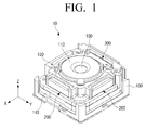
- FIG. 1 is a perspective view illustrating an optical adjusting apparatus, according to an embodiment of the present disclosure
- FIG. 2 is an exploded perspective view illustrating the optical adjusting apparatus of FIG. 1 ;
- FIG. 3 is a plan view illustrating the optical adjusting apparatus of FIG. 1 ;
- FIG. 4 is a side view illustrating the optical adjusting apparatus of FIG. 1 ;
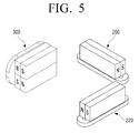
- FIG. 5 is a perspective view schematically illustrating arrangement of an image stabilization VCM actuator unit and an auto focusing VCM actuator unit of FIG. 2 ;
- FIGS. 6 to 9 are perspective views illustrating relationships between the driving axes and the magnets of FIG. 5 ;
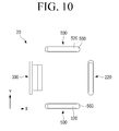
- FIG. 10 is a diagram schematically illustrating arrangement of an image stabilization actuator unit and an auto focus actuator unit, according to another embodiment of the present disclosure.
- FIG. 11 is a diagram schematically illustrating arrangement of an image stabilization actuator unit and an auto focus actuator unit, according to yet another embodiment of the present disclosure.
- FIG. 1 is a perspective view illustrating an optical adjusting apparatus 10, according to an embodiment of the present disclosure.
- FIG. 2 is an exploded perspective view illustrating the optical adjusting apparatus 10 of FIG. 1 .
- an optical adjusting apparatus 10 includes an optical adjusting lens 100, a lens barrel 110, a lens holder 120, a first base 140, a second base 160, an image stabilization voice coil motor (VCM) actuator unit 200, and an auto focusing VCM actuator unit 300.
- VCM image stabilization voice coil motor
- the optical adjusting apparatus 10 is a module in which an image stabilization function for preventing degradation of the sharpness of images due to a hand shake of a user and an auto focus function for automatically adjusting a focus are integrated.
- a camera module with a camera function has a module for the image stabilization function that is separate from a module for the auto focus function.
- the camera module with separate modules is not suitable for small electronic devices such as smart phones, etc., due to volume of each of the modules. Therefore, an optical adjusting apparatus in which the two functions are integrated is mounted in the small electronic devices.
- the optical adjusting lens 100 is moved in a first and second axes plane (X-Y plane) for image stabilization through driving of the image stabilization VCM actuator unit 200, or is moved on along an optical axis (Z-axis) for adjusting a focus through driving of the auto focusing VCM actuator unit 300.
- X-Y plane first and second axes plane
- Z-axis optical axis
- the image stabilization VCM actuator unit 200 and the auto focusing VCM actuator unit 300 will be described later.
- the lens barrel 110 houses the optical adjusting lens 100, and has a cylindrical shape. An opening (not illustrated) is formed in the lens barrel 110 so that light can penetrate a center of the lens barrel 110 in an optical axis direction (Z-axis direction).
- the lens barrel 110 in which the optical adjusting lens 100 is disposed is mounted to the lens holder 120.
- the lens holder 120 is moved in a first direction (X-axis direction) and a second direction (Y-axis direction) perpendicular to each other, and in the optical axis direction (Z-axis direction) perpendicular to both the first direction (X-axis direction) and the second direction (Y-axis direction).
- the first base 140 supports the lens holder 120 to move in the first direction (X-axis direction) perpendicular to the optical axis direction (Z-axis direction) and in the second direction (Y-axis direction) perpendicular to the first direction (X-axis direction). Then, the first base 140 itself moves in the optical axis direction (Z-axis direction) along with the lens holder 120 when adjusting the focus as described below.
- the second base 160 supports the first base 140 to move in the optical axis direction (Z-axis direction). In addition, the second base 160 supports various parts of the optical adjusting apparatus 10 as described above.
- the image stabilization VCM actuator unit 200 moves the lens holder 120 in the first direction (X-axis direction) and the second direction (Y-axis direction) for the image stabilization.
- the auto focusing VCM actuator unit 300 moves the lens holder 120 and the first base 140 in the optical axis direction (Z-axis direction) for auto focusing.
- the image stabilization VCM actuator unit 200 includes a first image stabilization VCM actuator 220 and a second image stabilization VCM actuator 260.
- the first image stabilization VCM actuator 220 includes a first image stabilization magnet 222 and a first image stabilization driving unit 226.
- the first image stabilization magnet 222 is disposed in a first side 122 of the lens holder 120.
- the first image stabilization magnet 222 is formed so that a neutral zone 224 thereof is orthogonal to the first direction (X-axis direction) and the second direction (Y-axis direction).
- the neutral zone 224 of the first image stabilization magnet 222 is formed parallel to the optical axis direction (Z-axis direction).
- the neutral zone 224 of the first image stabilization magnet 222 will be described in detail hereinafter with reference to accompanying drawings.
- the first image stabilization driving unit 226 is disposed in a position to face the first image stabilization magnet 222. In detail, the first image stabilization driving unit 226 is disposed below the first image stabilization magnet 222.
- the first image stabilization driving unit 226 is made up of a coil that can receive current applied from the outside to generate an electromagnetic force. Accordingly, the first image stabilization driving unit 226 performs electromagnetic interaction with the first image stabilization magnet 222.
- the second image stabilization VCM actuator 260 includes a second image stabilization magnet 262 and a second image stabilization driving unit 266.
- the second image stabilization magnet 262 is disposed in a second side 124 of the lens holder 120 to be arranged asymmetrically with respect to the first image stabilization magnet 222.
- the first image stabilization magnet 222 and the second image stabilization magnet 262 are disposed symmetrically with respect to the optical axis but do not face each other (i.e., not opposite of each other).
- the second image stabilization magnet 262 is formed so that a neutral zone 264 thereof is orthogonal to the first direction (X-axis direction) and the second direction (Y-axis direction) like the first image stabilization magnet 222.
- the neutral zone 264 of the second image stabilization magnet 262 is formed parallel to the optical axis direction (Z-axis direction) like the neutral zone 224 in the first image stabilization magnet 222.
- the neutral zone 264 of the second image stabilization magnet 262 will be described in detail hereinafter with reference to accompanying drawings.
- the second image stabilization driving unit 266 is made up of a coil that can receive current applied from the outside to generate an electromagnetic force like the first image stabilization driving unit 226. Accordingly, the second image stabilization driving unit 266 performs electromagnetic interaction with the second image stabilization magnet 262.
- the first image stabilization driving unit 226 and the second image stabilization driving unit 266 are made up of printed coils, and are respectively formed in a single driving unit receiving member 250.
- the driving unit receiving member 250 is provided with the first image stabilization driving unit 226 and the second image stabilization driving unit 266, and is disposed on a top surface of the first base 140.
- each of the first image stabilization driving unit 226 and the second image stabilization driving unit 266 may be formed of a normal driving coil other than the printed coil, and may be disposed on the top surface of the first base 140 without the separate driving unit receiving member 250.
- a plurality of ball bearings 150 is disposed between the lens holder 120 and the first base 140.
- the plurality of ball bearings 150 is slidably received in a plurality of ball bearing receiving grooves 142 disposed at intervals on a surface of the first base 140.
- the plurality of ball bearings 150 slidably supports the bottom surface of the lens holder 120 to face the top surface of the first base 140. Accordingly, when hand-shake occurs, the lens holder 120 may be moved in the first direction (X-axis direction) and the second direction (Y-axis direction) so as to sharpen images from data obtained from an image pickup device (not illustrated), thereby reducing the hand-shake.
- a first light passing hole 145 through which the light having passed through the optical adjusting lens 100 of the lens holder 120 can pass is formed in the first base 140 to penetrate the first base 140.
- the position and size of the first light passing hole 145 may be determined so that, considering a maximum distance that the optical adjusting lens 100 can move in the first direction (X-axis direction) and the second direction (Y-axis direction), the light having passed through the optical adjusting lens 100 in any position within a moving range of the lens holder 120 can pass through the first light passing hole 145.
- the second base 160 includes a side base 162 and a bottom base 166.
- the side base 162 forms a side surface of the optical adjusting apparatus 10.
- the side base 162 is connected to a side surface of the bottom base 166 by welding, screws, or other connectors known in the art.
- the bottom base 166 forms a bottom surface of the optical adjusting apparatus 10.
- a second light passing hole 168 through which the light having passed through the optical adjusting lens 100 of the lens holder 120 can pass is formed to penetrate the bottom base 166.
- the auto focusing VCM actuator unit 300 includes an auto focusing magnet 320 and an auto focusing driving unit 360.
- the auto focusing magnet 320 is disposed in a side surface 146 of the first base 140.
- the auto focusing magnet 320 is formed so that a neutral zone 324 thereof is orthogonal to the optical axis direction (Z-axis direction).
- the neutral zone 324 of the auto focusing magnet 320 is formed parallel to the first direction (X-axis direction) and the second direction (Y-axis direction).
- the neutral zone 324 of the auto focusing magnet 320 will be described in detail hereinafter with reference to the accompanying drawings.
- the auto focusing driving unit 360 is disposed in a position to face the auto focusing magnet 320, and is mounted to the side base 162. In detail, the auto focusing driving unit 360 is disposed behind the auto focusing magnet 320.
- the auto focusing driving unit 360 is made up of a coil that can receive current applied from the outside and can generate the electromagnetic force. Accordingly, the auto focusing driving unit 360 performs electromagnetic interaction with the first image stabilization magnet 222.
- the optical adjusting apparatus 10 can independently control each of the actuators, thereby independently providing a driving force with respect to each of the directions (X-axis, Y-axis, and Z-axis directions).
- the plurality of ball bearings 150 is disposed between the first base 140 and the side base 162.
- the plurality of ball bearings 150 is slidably received in a plurality of ball bearings receiving grooves 163 that are disposed at intervals on a surface of the side base 162.
- the plurality of ball bearings 150 slidably supports a side surface of the first base 140 to face a front surface of the side base 162. Therefore, when automatically adjusting the focus, the lens holder 120 can be moved in the optical axis direction (Z-axis direction) by moving the first base 140 in the optical axis direction (Z-axis direction) so that the focus can automatically be adjusted.
- the optical adjusting apparatus 10 includes a plurality of detecting units 182, 184, and 186, and a plurality of yokes 192, 194, and 196.
- the plurality of detecting units 182, 184, and 186 includes a first detecting unit 182, a second detecting unit 184, and a third detecting unit 186.
- the first detecting unit 182 is provided in the first base 140, and is disposed across from the first image stabilization driving unit 226 on the opposite side of the first image stabilization magnet 222.
- the first detecting unit 182 detects movement of the lens holder 120 in the first direction (X-axis direction), and may consist of a hall sensor that detects changes in the magnitude of voltage or current induced depending on the intensity of magnetic field.
- the second detecting unit 184 is provided in the first base 140, and is disposed across from the second image stabilization driving unit 266 on the opposite side of the second image stabilization magnet 262.
- the second detecting unit 184 detects movement of the lens holder 120 in the second direction (Y-axis direction), and may consist of a hall sensor like the first detecting unit 182.
- the third detecting unit 186 is provided in the side base 162, and is disposed on the opposite side of the auto focusing magnet 320.
- the third detecting unit 186 detects movement of the first base 140 in the optical axis direction (Z-axis direction), and may consist of a hall sensor like the first detecting unit 182 and the second detecting unit 184.
- the optical pickup apparatus 10 may control the movement of the lens holder 120 to a desired position based on a position of the lens holder 120 detected by the first, second and third detecting unit 182, 184, and 186.
- the plurality of yokes 192, 194, and 196 includes a first yoke 192, a second yoke 194, and a third yoke 196.
- the first yoke 192 is provided in the first base 140, and is disposed in a position facing the first image stabilization magnet 222.
- the first yoke 192 and the first image stabilization magnet 222 are magnetically attracted to each other.
- the second yoke 194 is provided in the first base 140, and is disposed in a position facing the second image stabilization magnet 262.
- the second yoke 194 and the second image stabilization magnet 262 are magnetically attracted to each other.
- the third yoke 196 is provided in the side base 162, and is disposed in a position facing the auto focusing magnet 320.
- the third yoke 196 and the auto focusing magnet 320 are magnetically attracted to each other.
- the optical adjusting apparatus 10 allows the lens holder 120 to be close to the first base 140 and to be returned to its initial position based on the magnetic attraction generated between each of the first and second yokes 192 and 194 and each of the first and second image stabilization magnets 222 and 262. Also, the optical adjusting apparatus 10 allows the first base 140 to be close to the side base 162 and to be returned to its initial position based on the magnetic attraction generated between the third yoke 196 and the auto focusing magnet 320.
- FIG. 3 is a plan view illustrating the optical adjusting apparatus 10 of FIG. 1 .
- the optical adjusting apparatus 10 can move the lens holder 120 in the first direction (X-axis direction) by providing a driving force Fx in the first direction (X-axis direction) using the first image stabilization VCM actuator 220. Then, the optical adjusting apparatus 10 can move the lens holder 120 in the second direction (Y-axis direction) by providing a driving force Fy in the second direction (Y-axis direction) using the second image stabilization VCM actuator 260.
- the auto focusing VCM actuator unit 300 is arranged to face the first image stabilization VCM actuator 220 around the optical adjusting lens 100.
- FIG. 4 is a side view illustrating the optical adjusting apparatus 10 of FIG. 1 .
- the optical adjusting apparatus 10 can move the lens holder 120 and the first base 140 in the optical axis direction (Z-axis direction) by providing a driving force Fz in the optical axis direction (Z-axis direction) using the auto focusing VCM actuator unit 300.
- the optical adjusting apparatus 10 can independently control movement according to each of the axis directions using the first image stabilization VCM actuator 220, the second image stabilization VCM actuator 260, and the auto focusing VCM actuator unit 300 provided separately. Therefore, when auto focusing is performed, accuracy of the position control may be improved.
- FIG. 5 is a perspective view schematically illustrating arrangement of the image stabilization VCM actuator unit 200 and the auto focusing VCM actuator unit 300 of FIG. 2 .
- the auto focusing VCM actuator unit 300 is disposed in a position facing the first image stabilization VCM actuator 220 as described above.
- the auto focusing VCM actuator unit 300 is not limited by this configuration; therefore, the auto focusing VCM actuator unit 300 may be disposed in a position facing the second image stabilization VCM actuator 260.
- FIGS. 6 to 9 are perspective views illustrating relationships between the driving axes and the magnets of FIG. 5 .
- the neutral zone 224 of the first image stabilization magnet 222, the neutral zone 264 of the second image stabilization magnet 262, and the neutral zone 324 of the auto focusing magnet 320 are formed to be orthogonal to the first direction (X-axis direction), the second direction (Y-axis direction), and the optical axis direction (Z-axis direction), respectively.
- the neutral zone 224 of the first image stabilization magnet 222 and the neutral zone 264 of the second image stabilization magnet 262 are formed parallel to the optical axis (Z-axis).
- the neutral zone refers to an interface surface between an N pole and an S pole of a magnet.
- the neutral zones 224, 264, and 324 of the magnets 222, 262, and 320 are formed through a magnetization process.
- the magnetization process refers to a process of creating a magnet from a ferromagnetic material of non-magnet.
- the magnetization process applies a strong extemal magnetic field to the ferromagnetic material to be manufactured into a magnet, thereby creating a permanent magnet.
- a surface of the ferromagnetic material that is in contact with a magnetization device applying the extemal magnetic field becomes an N pole (or an S pole), and the other surface thereof automatically becomes an S pole (or an N pole).
- an interface surface between the automatically generated N pole and S pole is called as the neutral zone.
- the magnets 222, 262, and 320 are manufactured such that the neutral zone 224 of the first image stabilization magnet 222 and the neutral zone 264 of the second image stabilization magnet 262 is formed in a vertical direction in FIG. 6 (Z-axis direction) through the magnetization process, and the neutral zone 324 of the auto focusing magnet 320 is formed in a horizontal direction in FIG. 6 (X-axis or Y-axis direction) through the magnetization process.
- first image stabilization magnet 222 and the second image stabilization magnet 262 are formed through a unipolar magnetization process, and the auto focusing magnet 320 is formed through a polarized magnetization process
- the polarized magnetization process applies the extemal magnetic field of two directions rather than the extemal magnetic field of one direction used the unipolar magnetization process.
- one side of the ferromagnetic material becomes the N pole, and the opposite side thereof becomes the S pole, and then, the opposite side of each of the N pole and the S pole becomes an S pole and an N pole.
- the interface surface between the N pole and the S pole is previously referred to as the neutral zone. In the case of the polarized magnetization process, there is more than one interface surface.
- the interface surface between the N pole and the S pole of the surface in contact with the magnetization device is much more conspicuous than the interface surface between the automatically generated N pole and S pole.
- a polarized magnetization magnet a multipole magnetization magnet (a magnet with split magnetization more than the polarized magnetization), or a magnet formed as a polarized magnetization magnet by bonding two unipolar magnetization magnets is used, a relatively more conspicuous interface surface is defined as the neutral zone.
- the auto focusing magnet 320 is manufactured using the polarized magnetization process so that the neutral zone 324 thereof is orthogonal to the optical axis direction (Z-axis direction) as illustrated in FIG. 6 .
- the image stabilization magnet and the auto focusing magnet may be formed through different magnetization processes (unipolar magnetization or split magnetization) as long as the neutral zone thereof can be formed to be orthogonal with respect to the moving direction.
- the neutral zone 224 of the first image stabilization magnet 222 is orthogonal (i.e., at a right angle ⁇ ) to a plane X formed in the first direction (X-axis direction).
- the neutral zone 264 of the second image stabilization magnet 262 is orthogonal (i.e., at a right angle ⁇ ) to a plane Y formed in the second direction (Y-axis direction).
- the neutral zone 324 of the auto focusing magnet 320 is orthogonal (i.e., at a right angle ⁇ ) to a plane Z formed in the optical axis direction (Z-axis direction).
- the optical adjusting apparatus 10 is formed so that the neutral zones 224, 264, and 324 of the magnets 222, 262, and 320 are orthogonal to moving directions along the three axes, respectively.
- the auto focusing magnet 320 of the optical adjusting apparatus 10 provided for movement in the optical axis direction (Z-axis direction)
- the neutral zone 324 thereof is orthogonal to the optical axis direction (Z-axis direction)
- the N pole and S pole of the auto focusing magnet 320 are formed vertically.
- a width d1 (shown in FIG. 6 ) of the auto focusing magnet 320 when the N pole and S pole thereof are formed in the vertical direction may be narrower than a width of another auto focusing magnet (not illustrated) in the first direction (X-axis direction) perpendicular to the optical axis direction (Z-axis direction) when the N pole and S pole of the other auto focusing magnet are formed in the horizontal direction (i.e., when the neutral zone is parallel to the optical axis direction).
- the auto focusing VCM actuator unit 300 for auto focusing may be placed to prevent a significant increase in the thickness of the side of the optical adjusting apparatus 10.
- the optical adjusting apparatus 10 since the optical adjusting apparatus 10 according to an embodiment of the present disclosure has a single module in which the image stabilization function and the auto focus function are integrated, movement in each of the three axes directions can be independently controlled, thus achieving a slimmer optical adjusting apparatus 10.
- FIG. 10 is a diagram schematically illustrating arrangement of an image stabilization actuator unit and an auto focus actuator unit, according to another embodiment of the present disclosure.
- an optical adjusting apparatus 20 includes a first image stabilization VCM actuator 220, a second image stabilization VCM actuator 500, and an auto focusing VCM actuator unit 300.
- the second image stabilization VCM actuator 500 includes a second image stabilization magnet 520 and a second image stabilization driving unit 560.
- the shape and function of each of the second image stabilization magnet 520 and the second image stabilization driving unit 560 are the same as those of the previous embodiment (e.g., the second image stabilization magnet 262 and the second image stabilization driving unit 266 illustrated in FIG. 2 ); therefore, description thereof will be omitted.
- Two second image stabilization VCM actuators 500 are provided, and each of the two second image stabilization VCM actuators 500 is disposed to face each other in the second direction (Y-axis direction). Since the optical adjusting apparatus 20 according to the present embodiment is equipped with a plurality of second image stabilization VCM actuators 500 to provide the driving force in the second direction (Y-axis direction), driving efficiency of the second direction (Y-axis direction) may be further increased.
- FIG. 11 is a diagram schematically illustrating arrangement of an image stabilization actuator unit and an auto focus actuator unit, according to yet another embodiment of the present disclosure.
- an optical adjusting apparatus 30 includes a first image stabilization VCM actuator 600, a second image stabilization VCM actuator 260, and an auto focusing VCM actuator unit 300.
- the first image stabilization VCM actuator 600 includes a first image stabilization magnet 620 and a first image stabilization driving unit 660.
- the shape and function of each of the first image stabilization magnet 620 and the first image stabilization driving unit 660 are the same as those of the previous embodiment (e.g., the first image stabilization magnet 222 and the first image stabilization driving unit 226 illustrated in FIG. 2 ); therefore, description thereof will be omitted.
- first image stabilization VCM actuators 600 are provided, and each of the first image stabilization VCM actuators 600 is disposed to face each other in the first direction (X-axis direction). Accordingly, the second image stabilization VCM actuator 260 and the auto focusing VCM actuator unit 300 are disposed to face each other in the second direction (Y-axis direction).
- the optical adjusting apparatus 30 is equipped with a plurality of first image stabilization VCM actuators 600 to provide the driving force in the first direction (X-axis direction), driving efficiency of the first direction (X-axis direction) may be further increased.
Landscapes
- Physics & Mathematics (AREA)
- Engineering & Computer Science (AREA)
- General Physics & Mathematics (AREA)
- Multimedia (AREA)
- Signal Processing (AREA)
- Electromagnetism (AREA)
- Combustion & Propulsion (AREA)
- Power Engineering (AREA)
- Chemical & Material Sciences (AREA)
- Optics & Photonics (AREA)
- Adjustment Of Camera Lenses (AREA)
- Lens Barrels (AREA)
- Studio Devices (AREA)
Abstract
Description
- This application claims the priority benefit under 35 U.S.C. § 119(a) from Korean Patent Application No.
10-2012-0144525 filed December 12, 2012 - The present disclosure relates to an optical adjusting apparatus. More particularly, the present disclosure relates to an optical adjusting apparatus in which an image stabilization function and an auto focus function are integrated.
- In recent years, slimmer electronic devices such as smart phones, etc. have emerged as a major subject. To create slimmer electronic devices, various attempts to slim down a variety of parts disposed inside the electronic devices have been performed.
- Various attempts to slim down camera modules provided in the electronic device such as a smart phone, etc. have also been performed. For example, a design trend of an optical adjusting apparatus included in the camera module is to implement an image stabilization function and an auto focus function within one module.
- However, conventional optical pickup apparatuses typically use magnets for implementing the image stabilization function and the auto focus function, which makes accurate position control for auto-focusing difficult.
- The present disclosure has been developed in order to overcome the above drawbacks and other problems associated with the conventional arrangement. An aspect of the present disclosure is to provide an optical adjusting apparatus in which an image stabilization function and an auto focus function are integrated, and that can accurately control a position when auto-focusing, and can thus slim down the apparatus.
- The above aspect and/or other feature of the present disclosure can substantially be achieved by providing an optical adjusting apparatus having an optical adjusting lens for image stabilization and auto focusing, which includes a lens holder that supports the optical adjusting lens, at least one image stabilization VCM actuator unit that moves the lens holder perpendicular to an optical axis of the optical adjusting lens, the image stabilization VCM actuator unit including a magnet with a neutral zone parallel to the optical axis, and an auto focusing VCM actuator unit that moves the lens holder in an optical axis direction, the auto focusing VCM actuator unit including a magnet with a neutral zone orthogonal to the optical axis.
- The auto focusing VCM actuator unit may be operated independently from the at least one image stabilization VCM actuator unit.
- The at least one image stabilization VCM actuator unit may include at least one first image stabilization VCM actuator that moves the lens holder in a first direction perpendicular to the optical axis, and at least one second image stabilization VCM actuator that moves the lens holder in a second direction perpendicular to both the optical axis and the first direction.
- The first image stabilization VCM actuator may include a first image stabilization magnet disposed in the lens holder, and a first image stabilization coil disposed to face the first image stabilization magnet so that the first image stabilization coil reacts with the first image stabilization magnet to move the lens holder in the first direction perpendicular to the optical axis. The second image stabilization VCM actuator may include a second image stabilization magnet disposed in the lens holder, and a second image stabilization coil disposed to face the second image stabilization magnet so that the second image stabilization coil reacts with the second image stabilization magnet to move the lens holder in the second direction perpendicular to the first direction.
- The auto focusing VCM actuator unit may include an auto focusing magnet disposed to face one of the first image stabilization magnet and the second image stabilization magnet, and an auto focusing coil disposed to face the auto focusing magnet so that the auto focusing coil reacts with the auto focusing magnet to move the lens holder in the optical direction.
- The first image stabilization magnet and the second image stabilization magnet may be disposed symmetrically with respect to the optical axis around the optical adjusting lens but may not face each other.
- The first image stabilization coil and the second image stabilization coil may be disposed below the first image stabilization magnet and the second image stabilization magnet, respectively.
- The auto focusing coil may be disposed behind the auto focusing magnet.
- The optical adjusting apparatus may include a first base on which the first image stabilization coil and the second image stabilization coil are disposed.
- The auto focusing magnet may be provided in the first base.
- The optical adjusting apparatus may include a second base in which the auto focusing coil is disposed.
- The optical adjusting apparatus may include a first detecting unit that is disposed in the first base and detects position movement of the lens holder in the first direction, and a second detecting unit that is disposed in the first base and detects position movement of the lens holder in the second direction.
- The optical adjusting apparatus may include a third detecting unit that is disposed in the second base and detects position movement of the lens holder in the optical axis direction.
- The at least one first image stabilization VCM actuator may include two first image stabilization VCM actuators disposed to face each other around the optical adjusting lens.
- The auto focusing VCM actuator unit may be disposed to face the at least one second image stabilization VCM actuator.
- The at least one second image stabilization VCM actuator may include two second image stabilization VCM actuators disposed to face each other around the optical adjusting lens.
- The auto focusing VCM actuator unit may be disposed to face the at least one first image stabilization VCM actuator.
- According to various embodiments of the present disclosure as described above, an optical adjusting apparatus is provided in which image stabilization function and auto focus function are integrated, can accurately control a position when auto focusing, and can be slimmed down.
- Other advantages and features of the present disclosure will become apparent from the following detailed description, which, taken in conjunction with the attached drawings, discloses preferred embodiments.
- These and/or other aspects and advantages of the present disclosure will become apparent and more readily appreciated from the following description of the embodiments, taken in conjunction with the accompanying drawings of which:
-
FIG. 1 is a perspective view illustrating an optical adjusting apparatus, according to an embodiment of the present disclosure; -
FIG. 2 is an exploded perspective view illustrating the optical adjusting apparatus ofFIG. 1 ; -
FIG. 3 is a plan view illustrating the optical adjusting apparatus ofFIG. 1 ; -
FIG. 4 is a side view illustrating the optical adjusting apparatus ofFIG. 1 ; -
FIG. 5 is a perspective view schematically illustrating arrangement of an image stabilization VCM actuator unit and an auto focusing VCM actuator unit ofFIG. 2 ; -
FIGS. 6 to 9 are perspective views illustrating relationships between the driving axes and the magnets ofFIG. 5 ; -
FIG. 10 is a diagram schematically illustrating arrangement of an image stabilization actuator unit and an auto focus actuator unit, according to another embodiment of the present disclosure; and -
FIG. 11 is a diagram schematically illustrating arrangement of an image stabilization actuator unit and an auto focus actuator unit, according to yet another embodiment of the present disclosure. - Throughout the drawings, like reference numerals will be understood to refer to like parts, components and structures.
- Hereinafter, certain exemplary embodiments of the present disclosure will be described in detail with reference to the accompanying drawings.
- The matters defined herein, such as a detailed construction and elements thereof, are provided to assist in a comprehensive understanding of this description. Thus, it is apparent that exemplary embodiments may be carried out without those defined matters. Also, well-known functions or constructions are omitted to provide a clear and concise description of exemplary embodiments. Further, dimensions of various elements in the accompanying drawings may be arbitrarily increased or decreased to assist in a comprehensive understanding.
-
FIG. 1 is a perspective view illustrating an optical adjustingapparatus 10, according to an embodiment of the present disclosure.FIG. 2 is an exploded perspective view illustrating the optical adjustingapparatus 10 ofFIG. 1 . - Referring to
FIGS. 1 and2 , anoptical adjusting apparatus 10 includes anoptical adjusting lens 100, alens barrel 110, alens holder 120, afirst base 140, asecond base 160, an image stabilization voice coil motor (VCM)actuator unit 200, and an auto focusingVCM actuator unit 300. - The
optical adjusting apparatus 10 is a module in which an image stabilization function for preventing degradation of the sharpness of images due to a hand shake of a user and an auto focus function for automatically adjusting a focus are integrated. Generally, a camera module with a camera function has a module for the image stabilization function that is separate from a module for the auto focus function. In this case, the camera module with separate modules is not suitable for small electronic devices such as smart phones, etc., due to volume of each of the modules. Therefore, an optical adjusting apparatus in which the two functions are integrated is mounted in the small electronic devices. - The
optical adjusting lens 100 is moved in a first and second axes plane (X-Y plane) for image stabilization through driving of the image stabilizationVCM actuator unit 200, or is moved on along an optical axis (Z-axis) for adjusting a focus through driving of the auto focusingVCM actuator unit 300. The image stabilizationVCM actuator unit 200 and the auto focusingVCM actuator unit 300 will be described later. - The
lens barrel 110 houses the optical adjustinglens 100, and has a cylindrical shape. An opening (not illustrated) is formed in thelens barrel 110 so that light can penetrate a center of thelens barrel 110 in an optical axis direction (Z-axis direction). - The
lens barrel 110 in which the optical adjustinglens 100 is disposed is mounted to thelens holder 120. By driving of the image stabilizationVCM actuator unit 200 and the auto focusingVCM actuator unit 300, thelens holder 120 is moved in a first direction (X-axis direction) and a second direction (Y-axis direction) perpendicular to each other, and in the optical axis direction (Z-axis direction) perpendicular to both the first direction (X-axis direction) and the second direction (Y-axis direction). - The
first base 140 supports thelens holder 120 to move in the first direction (X-axis direction) perpendicular to the optical axis direction (Z-axis direction) and in the second direction (Y-axis direction) perpendicular to the first direction (X-axis direction). Then, thefirst base 140 itself moves in the optical axis direction (Z-axis direction) along with thelens holder 120 when adjusting the focus as described below. - The
second base 160 supports thefirst base 140 to move in the optical axis direction (Z-axis direction). In addition, thesecond base 160 supports various parts of the optical adjustingapparatus 10 as described above. - The image stabilization
VCM actuator unit 200 moves thelens holder 120 in the first direction (X-axis direction) and the second direction (Y-axis direction) for the image stabilization. - The auto focusing
VCM actuator unit 300 moves thelens holder 120 and thefirst base 140 in the optical axis direction (Z-axis direction) for auto focusing. - Hereinafter, the image stabilization
VCM actuator unit 200 and the auto focusingVCM actuator unit 300 will be described in detail. - Referring to
FIG. 2 , the image stabilizationVCM actuator unit 200 includes a first imagestabilization VCM actuator 220 and a second imagestabilization VCM actuator 260. - The first image
stabilization VCM actuator 220 includes a firstimage stabilization magnet 222 and a first imagestabilization driving unit 226. - The first
image stabilization magnet 222 is disposed in afirst side 122 of thelens holder 120. The firstimage stabilization magnet 222 is formed so that aneutral zone 224 thereof is orthogonal to the first direction (X-axis direction) and the second direction (Y-axis direction). In other words, theneutral zone 224 of the firstimage stabilization magnet 222 is formed parallel to the optical axis direction (Z-axis direction). Theneutral zone 224 of the firstimage stabilization magnet 222 will be described in detail hereinafter with reference to accompanying drawings. - The first image
stabilization driving unit 226 is disposed in a position to face the firstimage stabilization magnet 222. In detail, the first imagestabilization driving unit 226 is disposed below the firstimage stabilization magnet 222. - The first image
stabilization driving unit 226 is made up of a coil that can receive current applied from the outside to generate an electromagnetic force. Accordingly, the first imagestabilization driving unit 226 performs electromagnetic interaction with the firstimage stabilization magnet 222. - The second image
stabilization VCM actuator 260 includes a secondimage stabilization magnet 262 and a second imagestabilization driving unit 266. - The second
image stabilization magnet 262 is disposed in asecond side 124 of thelens holder 120 to be arranged asymmetrically with respect to the firstimage stabilization magnet 222. In other words, the firstimage stabilization magnet 222 and the secondimage stabilization magnet 262 are disposed symmetrically with respect to the optical axis but do not face each other (i.e., not opposite of each other). The secondimage stabilization magnet 262 is formed so that aneutral zone 264 thereof is orthogonal to the first direction (X-axis direction) and the second direction (Y-axis direction) like the firstimage stabilization magnet 222. In other words, theneutral zone 264 of the secondimage stabilization magnet 262 is formed parallel to the optical axis direction (Z-axis direction) like theneutral zone 224 in the firstimage stabilization magnet 222. Theneutral zone 264 of the secondimage stabilization magnet 262 will be described in detail hereinafter with reference to accompanying drawings. - The second image
stabilization driving unit 266 is made up of a coil that can receive current applied from the outside to generate an electromagnetic force like the first imagestabilization driving unit 226. Accordingly, the second imagestabilization driving unit 266 performs electromagnetic interaction with the secondimage stabilization magnet 262. - Here, the first image
stabilization driving unit 226 and the second imagestabilization driving unit 266 are made up of printed coils, and are respectively formed in a single drivingunit receiving member 250. The drivingunit receiving member 250 is provided with the first imagestabilization driving unit 226 and the second imagestabilization driving unit 266, and is disposed on a top surface of thefirst base 140. - On the other hand, each of the first image
stabilization driving unit 226 and the second imagestabilization driving unit 266 may be formed of a normal driving coil other than the printed coil, and may be disposed on the top surface of thefirst base 140 without the separate drivingunit receiving member 250. - A plurality of
ball bearings 150 is disposed between thelens holder 120 and thefirst base 140. The plurality ofball bearings 150 is slidably received in a plurality of ballbearing receiving grooves 142 disposed at intervals on a surface of thefirst base 140. - Accordingly, the plurality of
ball bearings 150 slidably supports the bottom surface of thelens holder 120 to face the top surface of thefirst base 140. Accordingly, when hand-shake occurs, thelens holder 120 may be moved in the first direction (X-axis direction) and the second direction (Y-axis direction) so as to sharpen images from data obtained from an image pickup device (not illustrated), thereby reducing the hand-shake. - Also, a first
light passing hole 145 through which the light having passed through theoptical adjusting lens 100 of thelens holder 120 can pass is formed in thefirst base 140 to penetrate thefirst base 140. The position and size of the firstlight passing hole 145 may be determined so that, considering a maximum distance that theoptical adjusting lens 100 can move in the first direction (X-axis direction) and the second direction (Y-axis direction), the light having passed through theoptical adjusting lens 100 in any position within a moving range of thelens holder 120 can pass through the firstlight passing hole 145. - The
second base 160 includes aside base 162 and abottom base 166. - The
side base 162 forms a side surface of the optical adjustingapparatus 10. Theside base 162 is connected to a side surface of thebottom base 166 by welding, screws, or other connectors known in the art. Thebottom base 166 forms a bottom surface of the optical adjustingapparatus 10. A secondlight passing hole 168 through which the light having passed through theoptical adjusting lens 100 of thelens holder 120 can pass is formed to penetrate thebottom base 166. - The auto focusing
VCM actuator unit 300 includes anauto focusing magnet 320 and an auto focusingdriving unit 360. - The
auto focusing magnet 320 is disposed in aside surface 146 of thefirst base 140. Theauto focusing magnet 320 is formed so that aneutral zone 324 thereof is orthogonal to the optical axis direction (Z-axis direction). In other words, theneutral zone 324 of theauto focusing magnet 320 is formed parallel to the first direction (X-axis direction) and the second direction (Y-axis direction). Theneutral zone 324 of theauto focusing magnet 320 will be described in detail hereinafter with reference to the accompanying drawings. - The auto focusing
driving unit 360 is disposed in a position to face theauto focusing magnet 320, and is mounted to theside base 162. In detail, the auto focusingdriving unit 360 is disposed behind theauto focusing magnet 320. - The auto focusing
driving unit 360 is made up of a coil that can receive current applied from the outside and can generate the electromagnetic force. Accordingly, the auto focusingdriving unit 360 performs electromagnetic interaction with the firstimage stabilization magnet 222. - Since the optical adjusting
apparatus 10 according to the present embodiment is provided with the first imagestabilization VCM actuator 220 to control movement in the first direction (X-axis direction), the second imagestabilization VCM actuator 260 to control movement in the second direction (Y-axis direction), and the auto focusingVCM actuator unit 300 to control movement in the optical axis direction (Z-axis direction), the optical adjustingapparatus 10 can independently control each of the actuators, thereby independently providing a driving force with respect to each of the directions (X-axis, Y-axis, and Z-axis directions). - The plurality of
ball bearings 150 is disposed between thefirst base 140 and theside base 162. The plurality ofball bearings 150 is slidably received in a plurality of ballbearings receiving grooves 163 that are disposed at intervals on a surface of theside base 162. - Accordingly, the plurality of
ball bearings 150 slidably supports a side surface of thefirst base 140 to face a front surface of theside base 162. Therefore, when automatically adjusting the focus, thelens holder 120 can be moved in the optical axis direction (Z-axis direction) by moving thefirst base 140 in the optical axis direction (Z-axis direction) so that the focus can automatically be adjusted. - Furthermore, the optical adjusting
apparatus 10 includes a plurality of detectingunits yokes - The plurality of detecting
units unit 182, a second detectingunit 184, and a third detectingunit 186. - The first detecting
unit 182 is provided in thefirst base 140, and is disposed across from the first imagestabilization driving unit 226 on the opposite side of the firstimage stabilization magnet 222. The first detectingunit 182 detects movement of thelens holder 120 in the first direction (X-axis direction), and may consist of a hall sensor that detects changes in the magnitude of voltage or current induced depending on the intensity of magnetic field. - The second detecting
unit 184 is provided in thefirst base 140, and is disposed across from the second imagestabilization driving unit 266 on the opposite side of the secondimage stabilization magnet 262. The second detectingunit 184 detects movement of thelens holder 120 in the second direction (Y-axis direction), and may consist of a hall sensor like the first detectingunit 182. - The third detecting
unit 186 is provided in theside base 162, and is disposed on the opposite side of theauto focusing magnet 320. The third detectingunit 186 detects movement of thefirst base 140 in the optical axis direction (Z-axis direction), and may consist of a hall sensor like the first detectingunit 182 and the second detectingunit 184. - The
optical pickup apparatus 10 according to the present embodiment may control the movement of thelens holder 120 to a desired position based on a position of thelens holder 120 detected by the first, second and third detectingunit - The plurality of
yokes first yoke 192, asecond yoke 194, and athird yoke 196. - The
first yoke 192 is provided in thefirst base 140, and is disposed in a position facing the firstimage stabilization magnet 222. Thefirst yoke 192 and the firstimage stabilization magnet 222 are magnetically attracted to each other. - The
second yoke 194 is provided in thefirst base 140, and is disposed in a position facing the secondimage stabilization magnet 262. Thesecond yoke 194 and the secondimage stabilization magnet 262 are magnetically attracted to each other. - The
third yoke 196 is provided in theside base 162, and is disposed in a position facing theauto focusing magnet 320. Thethird yoke 196 and theauto focusing magnet 320 are magnetically attracted to each other. - Accordingly, the optical adjusting
apparatus 10 allows thelens holder 120 to be close to thefirst base 140 and to be returned to its initial position based on the magnetic attraction generated between each of the first andsecond yokes image stabilization magnets apparatus 10 allows thefirst base 140 to be close to theside base 162 and to be returned to its initial position based on the magnetic attraction generated between thethird yoke 196 and theauto focusing magnet 320. -
FIG. 3 is a plan view illustrating the optical adjustingapparatus 10 ofFIG. 1 . - Referring to
FIG. 3 , the optical adjustingapparatus 10 can move thelens holder 120 in the first direction (X-axis direction) by providing a driving force Fx in the first direction (X-axis direction) using the first imagestabilization VCM actuator 220. Then, the optical adjustingapparatus 10 can move thelens holder 120 in the second direction (Y-axis direction) by providing a driving force Fy in the second direction (Y-axis direction) using the second imagestabilization VCM actuator 260. - Moreover, when viewed from above, the auto focusing
VCM actuator unit 300 is arranged to face the first imagestabilization VCM actuator 220 around theoptical adjusting lens 100. -
FIG. 4 is a side view illustrating the optical adjustingapparatus 10 ofFIG. 1 . - Referring to
FIG. 4 , the optical adjustingapparatus 10 can move thelens holder 120 and thefirst base 140 in the optical axis direction (Z-axis direction) by providing a driving force Fz in the optical axis direction (Z-axis direction) using the auto focusingVCM actuator unit 300. - As a result, the optical adjusting
apparatus 10 according to an embodiment can independently control movement according to each of the axis directions using the first imagestabilization VCM actuator 220, the second imagestabilization VCM actuator 260, and the auto focusingVCM actuator unit 300 provided separately. Therefore, when auto focusing is performed, accuracy of the position control may be improved. - Here, independently means that the driving force Fx of the first direction (X-axis direction) generates only displacement of the first direction (X-axis direction) but does not affect a position of the second direction (Y-axis direction) and the optical axis direction (Z-axis direction), the driving force Fy of the second direction (Y-axis direction) generates only displacement of the second direction (Y-axis direction) but does not affect a position of the first direction (X-axis direction) and the optical axis direction (Z-axis direction), and the driving force Fz of the optical axis direction (Z-axis direction) generates only displacement of the optical axis direction (Z-axis direction) but does not affect a position of the first direction (X-axis direction) and the second direction (Y-axis direction).
-
FIG. 5 is a perspective view schematically illustrating arrangement of the image stabilizationVCM actuator unit 200 and the auto focusingVCM actuator unit 300 ofFIG. 2 . - Referring to
FIG. 5 , the auto focusingVCM actuator unit 300 is disposed in a position facing the first imagestabilization VCM actuator 220 as described above. However, the auto focusingVCM actuator unit 300 is not limited by this configuration; therefore, the auto focusingVCM actuator unit 300 may be disposed in a position facing the second imagestabilization VCM actuator 260. -
FIGS. 6 to 9 are perspective views illustrating relationships between the driving axes and the magnets ofFIG. 5 . - Referring to
FIG. 6 , theneutral zone 224 of the firstimage stabilization magnet 222, theneutral zone 264 of the secondimage stabilization magnet 262, and theneutral zone 324 of theauto focusing magnet 320 are formed to be orthogonal to the first direction (X-axis direction), the second direction (Y-axis direction), and the optical axis direction (Z-axis direction), respectively. In other words, theneutral zone 224 of the firstimage stabilization magnet 222 and theneutral zone 264 of the secondimage stabilization magnet 262 are formed parallel to the optical axis (Z-axis). - Here, the neutral zone refers to an interface surface between an N pole and an S pole of a magnet. The
neutral zones magnets - In the present embodiment, the
magnets neutral zone 224 of the firstimage stabilization magnet 222 and theneutral zone 264 of the secondimage stabilization magnet 262 is formed in a vertical direction inFIG. 6 (Z-axis direction) through the magnetization process, and theneutral zone 324 of theauto focusing magnet 320 is formed in a horizontal direction inFIG. 6 (X-axis or Y-axis direction) through the magnetization process. - Furthermore, the first
image stabilization magnet 222 and the secondimage stabilization magnet 262 are formed through a unipolar magnetization process, and theauto focusing magnet 320 is formed through a polarized magnetization process - Here, the polarized magnetization process applies the extemal magnetic field of two directions rather than the extemal magnetic field of one direction used the unipolar magnetization process. After the magnetization is performed using the polarized magnetization process, one side of the ferromagnetic material becomes the N pole, and the opposite side thereof becomes the S pole, and then, the opposite side of each of the N pole and the S pole becomes an S pole and an N pole. The interface surface between the N pole and the S pole is previously referred to as the neutral zone. In the case of the polarized magnetization process, there is more than one interface surface. However, when a magnetic flux direction is considered, since the flux perpendicularly diverges and converges through the surface in contact with the magnetization device, the interface surface between the N pole and the S pole of the surface in contact with the magnetization device is much more conspicuous than the interface surface between the automatically generated N pole and S pole. Generally, if a polarized magnetization magnet, a multipole magnetization magnet (a magnet with split magnetization more than the polarized magnetization), or a magnet formed as a polarized magnetization magnet by bonding two unipolar magnetization magnets is used, a relatively more conspicuous interface surface is defined as the neutral zone.
- In the present embodiment, the
auto focusing magnet 320 is manufactured using the polarized magnetization process so that theneutral zone 324 thereof is orthogonal to the optical axis direction (Z-axis direction) as illustrated inFIG. 6 . However, this is only one example, therefore, the image stabilization magnet and the auto focusing magnet may be formed through different magnetization processes (unipolar magnetization or split magnetization) as long as the neutral zone thereof can be formed to be orthogonal with respect to the moving direction. - Referring to
FIG. 7 , theneutral zone 224 of the firstimage stabilization magnet 222 is orthogonal (i.e., at a right angle θ) to a plane X formed in the first direction (X-axis direction). Referring toFIG. 8 , theneutral zone 264 of the secondimage stabilization magnet 262 is orthogonal (i.e., at a right angle θ) to a plane Y formed in the second direction (Y-axis direction). Referring toFIG. 9 , theneutral zone 324 of theauto focusing magnet 320 is orthogonal (i.e., at a right angle θ) to a plane Z formed in the optical axis direction (Z-axis direction). - As described above, the optical adjusting
apparatus 10 according to an embodiment of the present disclosure is formed so that theneutral zones magnets auto focusing magnet 320 of the optical adjustingapparatus 10, provided for movement in the optical axis direction (Z-axis direction), is formed so that theneutral zone 324 thereof is orthogonal to the optical axis direction (Z-axis direction), the N pole and S pole of theauto focusing magnet 320 are formed vertically. - Accordingly, a width d1 (shown in
FIG. 6 ) of theauto focusing magnet 320 when the N pole and S pole thereof are formed in the vertical direction may be narrower than a width of another auto focusing magnet (not illustrated) in the first direction (X-axis direction) perpendicular to the optical axis direction (Z-axis direction) when the N pole and S pole of the other auto focusing magnet are formed in the horizontal direction (i.e., when the neutral zone is parallel to the optical axis direction). Therefore, in the present embodiment, since the thickness of theauto focusing magnet 320 in the first direction (X-axis direction) can be reduced, the auto focusingVCM actuator unit 300 for auto focusing may be placed to prevent a significant increase in the thickness of the side of the optical adjustingapparatus 10. - Accordingly, since the optical adjusting
apparatus 10 according to an embodiment of the present disclosure has a single module in which the image stabilization function and the auto focus function are integrated, movement in each of the three axes directions can be independently controlled, thus achieving a slimmer optical adjustingapparatus 10. -
FIG. 10 is a diagram schematically illustrating arrangement of an image stabilization actuator unit and an auto focus actuator unit, according to another embodiment of the present disclosure. - In the present embodiment, the same parts as those of the previous embodiment will be indicated as the same reference numerals, and descriptions thereof will be omitted. Hereinafter, the present embodiment will be described based on the differences from the previous embodiment.
- Referring to
FIG. 10 , anoptical adjusting apparatus 20 includes a first imagestabilization VCM actuator 220, a second imagestabilization VCM actuator 500, and an auto focusingVCM actuator unit 300. - The second image
stabilization VCM actuator 500 includes a secondimage stabilization magnet 520 and a second imagestabilization driving unit 560. The shape and function of each of the secondimage stabilization magnet 520 and the second imagestabilization driving unit 560 are the same as those of the previous embodiment (e.g., the secondimage stabilization magnet 262 and the second imagestabilization driving unit 266 illustrated inFIG. 2 ); therefore, description thereof will be omitted. - Two second image
stabilization VCM actuators 500 are provided, and each of the two second imagestabilization VCM actuators 500 is disposed to face each other in the second direction (Y-axis direction). Since the optical adjustingapparatus 20 according to the present embodiment is equipped with a plurality of second imagestabilization VCM actuators 500 to provide the driving force in the second direction (Y-axis direction), driving efficiency of the second direction (Y-axis direction) may be further increased. -
FIG. 11 is a diagram schematically illustrating arrangement of an image stabilization actuator unit and an auto focus actuator unit, according to yet another embodiment of the present disclosure. - In the present embodiment, the same parts as those of the previous embodiment will be indicated as the same reference numerals, and descriptions thereof will be omitted. Hereinafter, the present embodiment will be described based on the differences from the previous embodiment.
- Referring to
FIG. 11 , anoptical adjusting apparatus 30 includes a first imagestabilization VCM actuator 600, a second imagestabilization VCM actuator 260, and an auto focusingVCM actuator unit 300. - The first image
stabilization VCM actuator 600 includes a firstimage stabilization magnet 620 and a first imagestabilization driving unit 660. The shape and function of each of the firstimage stabilization magnet 620 and the first imagestabilization driving unit 660 are the same as those of the previous embodiment (e.g., the firstimage stabilization magnet 222 and the first imagestabilization driving unit 226 illustrated inFIG. 2 ); therefore, description thereof will be omitted. - Two first image
stabilization VCM actuators 600 are provided, and each of the first imagestabilization VCM actuators 600 is disposed to face each other in the first direction (X-axis direction). Accordingly, the second imagestabilization VCM actuator 260 and the auto focusingVCM actuator unit 300 are disposed to face each other in the second direction (Y-axis direction). - Since the optical adjusting
apparatus 30 according to the present embodiment is equipped with a plurality of first imagestabilization VCM actuators 600 to provide the driving force in the first direction (X-axis direction), driving efficiency of the first direction (X-axis direction) may be further increased. - All references, including publications, patent applications, and patents, cited herein are hereby incorporated by reference to the same extent as if each reference were individually and specifically indicated to be incorporated by reference and were set forth in its entirety herein.
- For the purposes of promoting an understanding of the principles of the invention, reference has been made to the embodiments illustrated in the drawings, and specific language has been used to describe these embodiments. However, no limitation of the scope of the invention is intended by this specific language, and the invention should be construed to encompass all embodiments that would normally occur to one of ordinary skill in the art. The terminology used herein is for the purpose of describing the particular embodiments and is not intended to be limiting of exemplary embodiments of the invention. In the description of the embodiments, certain detailed explanations of related art are omitted when it is deemed that they may unnecessarily obscure the essence of the invention.
- The use of any and all examples, or exemplary language (e.g., "such as") provided herein, is intended merely to better illuminate the invention and does not pose a limitation on the scope of the invention unless otherwise claimed. Numerous modifications and adaptations will be readily apparent to those of ordinary skill in this art without departing from the spirit and scope of the invention as defined by the following claims. Therefore, the scope of the invention is defined not by the detailed description of the invention but by the following claims, and all differences within the scope will be construed as being included in the invention.
- No item or component is essential to the practice of the invention unless the element is specifically described as "essential" or "critical". It will also be recognized that the terms "comprises," "comprising," "includes," "including," "has," and "having," as used herein, are specifically intended to be read as open-ended terms of art. The use of the terms "a" and "an" and "the" and similar referents in the context of describing the invention (especially in the context of the following claims) are to be construed to cover both the singular and the plural, unless the context clearly indicates otherwise. In addition, it should be understood that although the terms "first," "second," etc. may be used herein to describe various elements, these elements should not be limited by these terms, which are only used to distinguish one element from another. Furthermore, recitation of ranges of values herein are merely intended to serve as a shorthand method of referring individually to each separate value falling within the range, unless otherwise indicated herein, and each separate value is incorporated into the specification as if it were individually recited herein.
- While the embodiments of the present disclosure have been described, additional variations and modifications of the embodiments may occur to those skilled in the art once they learn of the basic inventive concepts. Therefore, it is intended that the appended claims shall be construed to include both the above embodiments and all such variations and modifications that fall within the spirit and scope of the inventive concepts.
Claims (15)
- An optical adjusting apparatus (10) having an optical adjusting lens (100) for image stabilization and auto focusing comprising:a lens holder (120) that supports the optical adjusting lens (100);at least one image stabilization voice coil motor (VCM) actuator unit (200) that moves the lens holder (120) perpendicular to an optical axis of the optical adjusting lens (100), the at least one image stabilization VCM actuator unit (200) comprising a magnet (222) with a neutral zone (224) parallel to the optical axis; andan auto focusing VCM actuator unit (300) that moves the lens holder (120) in an optical axis direction, the auto focusing VCM actuator unit (300) comprising a magnet (320) with a neutral zone (324) orthogonal to the optical axis.
- The optical adjusting apparatus (10) of claim 1, wherein the auto focusing VCM actuator unit (300) is operated independently from the at least one image stabilization VCM actuator unit (200).
- The optical adjusting apparatus (10) of claim 2, wherein the at least one image stabilization VCM actuator unit (200) comprises:at least one first image stabilization VCM actuator (220) that moves the lens holder (120) in a first direction perpendicular to the optical axis; andat least one second image stabilization VCM actuator (260) that moves the lens holder (120) in a second direction perpendicular to both the optical axis and the first direction.
- The optical adjusting apparatus (10) of claim 3, wherein:the at least one first image stabilization VCM actuator (220) comprises:a first image stabilization magnet (222) disposed in the lens holder (120); anda first image stabilization coil (226) disposed to face the first image stabilization magnet (222) so that the first image stabilization coil (226) reacts with the first image stabilization magnet (222) to move the lens holder (120) in the first direction perpendicular to the optical axis, andthe second image stabilization VCM actuator (260) comprises :a second image stabilization magnet (262) disposed in the lens holder (120); anda second image stabilization coil (266) disposed to face the second image stabilization magnet so that the second image stabilization coil (266) reacts with the second image stabilization magnet (262) to move the lens holder (120) in the second direction perpendicular to the first direction.
- The optical adjusting apparatus (10) of claim 4, wherein the auto focusing VCM actuator unit (300) comprises:an auto focusing magnet (320) disposed to face one of the first image stabilization magnet (222) and the second image stabilization magnet (262); andan auto focusing coil disposed to face the auto focusing magnet (320) so that the auto focusing coil reacts with the auto focusing magnet (320) to move the lens holder (120) in the optical axis direction.
- The optical adjusting apparatus (10) of claim 4, wherein the first image stabilization magnet (222) and the second image stabilization magnet (262) are disposed symmetrically with respect to the optical axis around the optical adjusting lens (100) but do not face each other.
- The optical adjusting apparatus (10) of claim 4, wherein the first image stabilization coil (226) and the second image stabilization coil (266) are disposed below the first image stabilization magnet (222) and the second image stabilization magnet (262), respectively.
- The optical adjusting apparatus (10) of claim 4, wherein each of the first image stabilization coil (226) and the second image stabilization coil (266) comprises a printed coil.
- The optical adjusting apparatus (10) of claim 5, wherein the auto focusing coil is disposed behind the auto focusing magnet (320).
- The optical adjusting apparatus (10) of claim 5, further comprising:a first base (140) on which the first image stabilization coil (226) and the second image stabilization coil (266) are disposed.
- The optical adjusting apparatus (10) of claim 10, wherein the auto focusing magnet (320) is provided in the first base (140).
- The optical adjusting apparatus of claim 11, further comprising:a second base (160) in which the auto focusing coil is disposed; anda third detecting unit (186) that is disposed in the second base (160) and detects position movement of the lens holder (120) in the optical axis direction.
- The optical adjusting apparatus (10) of claim 10, further comprising:a first detecting unit (182) that is disposed in the first base (140) and detects position movement of the lens holder (120) in the first direction; anda second detecting unit (184) that is disposed in the first base (140) and detects position movement of the lens holder (120) in the second direction.
- The optical adjusting apparatus (10) of claim 3, wherein
the at least one first image stabilization VCM actuator (600) comprises two first image stabilization VCM actuators (600) disposed to face each other around the optical adjusting lens (100); and
the auto focusing VCM actuator unit (300) is disposed to face the at least one second image stabilization VCM actuator (260). - The optical adjusting apparatus (10) of claim 3, wherein
the at least one second image stabilization VCM actuator (500) comprises two second image stabilization VCM actuators (500) disposed to face each other around the optical adjusting lens; and
the auto focusing VCM actuator unit (300) is disposed to face the at least one first image stabilization VCM actuator (220).
Priority Applications (2)
| Application Number | Priority Date | Filing Date | Title |
|---|---|---|---|
| EP22184031.7A EP4095588B1 (en) | 2012-12-12 | 2013-11-22 | Optical adjusting apparatus |
| EP23185560.2A EP4236045A3 (en) | 2012-12-12 | 2013-11-22 | Optical adjusting apparatus |
Applications Claiming Priority (1)
| Application Number | Priority Date | Filing Date | Title |
|---|---|---|---|
| KR1020120144525A KR101960493B1 (en) | 2012-12-12 | 2012-12-12 | Optical adjusting apparatus |
Related Child Applications (4)
| Application Number | Title | Priority Date | Filing Date |
|---|---|---|---|
| EP23185560.2A Division EP4236045A3 (en) | 2012-12-12 | 2013-11-22 | Optical adjusting apparatus |
| EP23185560.2A Division-Into EP4236045A3 (en) | 2012-12-12 | 2013-11-22 | Optical adjusting apparatus |
| EP22184031.7A Division EP4095588B1 (en) | 2012-12-12 | 2013-11-22 | Optical adjusting apparatus |
| EP22184031.7A Division-Into EP4095588B1 (en) | 2012-12-12 | 2013-11-22 | Optical adjusting apparatus |
Publications (3)
| Publication Number | Publication Date |
|---|---|
| EP2743750A1 true EP2743750A1 (en) | 2014-06-18 |
| EP2743750B1 EP2743750B1 (en) | 2023-10-25 |
| EP2743750C0 EP2743750C0 (en) | 2023-10-25 |
Family
ID=49955810
Family Applications (3)
| Application Number | Title | Priority Date | Filing Date |
|---|---|---|---|
| EP22184031.7A Active EP4095588B1 (en) | 2012-12-12 | 2013-11-22 | Optical adjusting apparatus |
| EP13194027.2A Active EP2743750B1 (en) | 2012-12-12 | 2013-11-22 | Optical adjusting apparatus |
| EP23185560.2A Pending EP4236045A3 (en) | 2012-12-12 | 2013-11-22 | Optical adjusting apparatus |
Family Applications Before (1)
| Application Number | Title | Priority Date | Filing Date |
|---|---|---|---|
| EP22184031.7A Active EP4095588B1 (en) | 2012-12-12 | 2013-11-22 | Optical adjusting apparatus |
Family Applications After (1)
| Application Number | Title | Priority Date | Filing Date |
|---|---|---|---|
| EP23185560.2A Pending EP4236045A3 (en) | 2012-12-12 | 2013-11-22 | Optical adjusting apparatus |
Country Status (11)
| Country | Link |
|---|---|
| US (1) | US9420183B2 (en) |
| EP (3) | EP4095588B1 (en) |
| KR (1) | KR101960493B1 (en) |
| CN (1) | CN103869445B (en) |
| AU (1) | AU2013357963B2 (en) |
| ES (1) | ES2961908T3 (en) |
| HU (1) | HUE063737T2 (en) |
| PL (1) | PL2743750T3 (en) |
| RU (1) | RU2635837C2 (en) |
| WO (1) | WO2014092271A1 (en) |
| ZA (1) | ZA201503898B (en) |
Cited By (3)
| Publication number | Priority date | Publication date | Assignee | Title |
|---|---|---|---|---|
| EP2813880A3 (en) * | 2013-06-10 | 2015-04-08 | Samsung Electronics Co., Ltd. | Camera lens assembly |
| EP3001234A1 (en) * | 2014-09-23 | 2016-03-30 | Samsung Electronics Co., Ltd. | Camera lens module |
| EP3591958B1 (en) * | 2015-09-30 | 2024-03-06 | Apple Inc. | Mobile zoom using multiple optical image stabilization cameras |
Families Citing this family (99)
| Publication number | Priority date | Publication date | Assignee | Title |
|---|---|---|---|---|
| KR101960506B1 (en) * | 2011-07-26 | 2019-07-16 | 삼성전자주식회사 | Position sensing assembly and optical device having the same |
| US8861946B2 (en) * | 2013-03-07 | 2014-10-14 | Jahwa Electronics Co., Ltd. | Device for driving camera lens module in portable terminal |
| CN105190429B (en) * | 2013-03-29 | 2018-09-14 | 磁化电子株式会社 | Camera lens module |
| TWI655490B (en) * | 2013-05-06 | 2019-04-01 | 台灣東電化股份有限公司 | Lens drive |
| CN105308947B (en) | 2013-06-13 | 2018-10-02 | 核心光电有限公司 | Dual Aperture Zoom Digital Video Camera |
| CN105359006B (en) | 2013-07-04 | 2018-06-22 | 核心光电有限公司 | Small Telephoto Lens Kit |
| EP3028443A2 (en) | 2013-08-01 | 2016-06-08 | Corephotonics Ltd. | Thin multi-aperture imaging system with auto-focus and methods for using same |
| US9372352B2 (en) | 2013-08-23 | 2016-06-21 | Samsung Electro-Mechanics Co., Ltd. | Lens driving device and camera module including the same |
| CN106062605A (en) * | 2013-10-04 | 2016-10-26 | 郑国星 | Lens driving device |
| US10133086B2 (en) | 2013-10-25 | 2018-11-20 | Jahwa Electronics Co., Ltd. | Camera lens module |
| US9964778B2 (en) | 2013-10-25 | 2018-05-08 | Jahwa Electronics Co., Ltd. | Camera lens module |
| WO2015060637A1 (en) | 2013-10-25 | 2015-04-30 | 자화전자(주) | Camera lens module |
| KR101725442B1 (en) * | 2014-03-07 | 2017-04-11 | 자화전자(주) | Camera lens module |
| US9618770B2 (en) | 2014-04-11 | 2017-04-11 | Samsung Electro-Mechanics Co., Ltd. | Camera module with function of auto-focus and image stabilize |
| KR101670139B1 (en) * | 2014-06-20 | 2016-10-27 | 삼성전기주식회사 | Camera module |
| US9955077B2 (en) | 2014-06-20 | 2018-04-24 | Samsung Electro-Mechanics Co., Ltd. | Camera module |
| KR102041647B1 (en) * | 2014-06-30 | 2019-11-07 | 삼성전기주식회사 | System and method for calibration of camera |
| KR101651458B1 (en) * | 2014-07-08 | 2016-08-26 | 자화전자(주) | Camera lens module |
| KR102255295B1 (en) * | 2014-07-24 | 2021-05-25 | 삼성전자주식회사 | Camera module |
| US9392188B2 (en) | 2014-08-10 | 2016-07-12 | Corephotonics Ltd. | Zoom dual-aperture camera with folded lens |
| US10634867B2 (en) | 2014-11-28 | 2020-04-28 | Samsung Electro-Mechanics Co., Ltd. | Camera module |
| KR101792328B1 (en) * | 2014-11-28 | 2017-11-02 | 삼성전기주식회사 | Camera module |
| KR20160067617A (en) * | 2014-12-04 | 2016-06-14 | 삼성전기주식회사 | Camera Module |
| KR102432734B1 (en) * | 2014-12-17 | 2022-08-17 | 엘지이노텍 주식회사 | Lens moving unit |
| KR102385409B1 (en) * | 2014-12-17 | 2022-04-11 | 엘지이노텍 주식회사 | Lens moving unit |
| WO2016108093A1 (en) | 2015-01-03 | 2016-07-07 | Corephotonics Ltd. | Miniature telephoto lens module and a camera utilizing such a lens module |
| KR102391030B1 (en) * | 2015-01-20 | 2022-04-26 | 엘지이노텍 주식회사 | Lens moving unit and camera module having the same |
| US10365121B2 (en) | 2015-02-06 | 2019-07-30 | Apple Inc. | Magnetic sensing for auto focus position detection |
| CN104776920B (en) * | 2015-03-26 | 2018-04-13 | 中国人民解放军国防科学技术大学 | Super-resolution infrared imaging is surely as integrated apparatus |
| KR102078978B1 (en) | 2015-04-16 | 2020-02-19 | 코어포토닉스 리미티드 | Auto focus and optical imagestabilization in a compact folded camera |
| KR101832568B1 (en) | 2015-05-20 | 2018-02-27 | 삼성전기주식회사 | Camera Module |
| US20160341975A1 (en) * | 2015-05-21 | 2016-11-24 | Jahwa Electronics Co., Ltd. | Camera lens module |
| KR101694881B1 (en) * | 2015-06-23 | 2017-01-23 | 자화전자(주) | Camera lens module |
| KR102460756B1 (en) * | 2015-08-11 | 2022-10-31 | 삼성전기주식회사 | Camera Module |
| WO2017025822A1 (en) | 2015-08-13 | 2017-02-16 | Corephotonics Ltd. | Dual aperture zoom camera with video support and switching / non-switching dynamic control |
| KR101955010B1 (en) * | 2015-09-22 | 2019-03-07 | 자화전자(주) | Camera lens module |
| CN106856553B (en) * | 2015-12-09 | 2019-12-17 | 台湾东电化股份有限公司 | Optical Image Stabilization Mechanism |
| KR101668720B1 (en) * | 2015-12-28 | 2016-10-24 | 자화전자(주) | Camera lens module |
| EP4024842A3 (en) | 2015-12-29 | 2022-08-31 | Corephotonics Ltd. | Dual-aperture zoom digital camera with automatic adjustable tele field of view |
| KR101652762B1 (en) * | 2016-01-22 | 2016-09-01 | (주) 엠디펄스 | Camera module |
| KR101704498B1 (en) * | 2016-03-10 | 2017-02-09 | 자화전자(주) | Apparatus for auto focus with 3 location supporting structure |
| EP3758356B1 (en) | 2016-05-30 | 2021-10-20 | Corephotonics Ltd. | Actuator |
| KR102646151B1 (en) | 2016-06-19 | 2024-03-08 | 코어포토닉스 리미티드 | Frame synchronization in a dual-aperture camera system |
| KR102657464B1 (en) * | 2016-07-07 | 2024-04-12 | 코어포토닉스 리미티드 | Linear ball guided voice coil motor for folded optic |
| CN109690887B (en) * | 2016-09-02 | 2022-05-17 | Lg伊诺特有限公司 | Optical output module and LIDAR |
| CN106716242A (en) * | 2016-10-24 | 2017-05-24 | 江西森阳科技股份有限公司 | Camera module |
| KR101823272B1 (en) * | 2016-12-01 | 2018-01-29 | 삼성전기주식회사 | Camera module |
| TWI614559B (en) * | 2016-12-05 | 2018-02-11 | 財團法人工業技術研究院 | Lens device |
| US11531209B2 (en) | 2016-12-28 | 2022-12-20 | Corephotonics Ltd. | Folded camera structure with an extended light-folding-element scanning range |
| EP4145206A1 (en) | 2017-01-12 | 2023-03-08 | Corephotonics Ltd. | Compact folded camera |
| CN114137791A (en) | 2017-03-15 | 2022-03-04 | 核心光电有限公司 | Camera device and mobile device with panoramic scanning range |
| KR102400516B1 (en) * | 2017-06-12 | 2022-05-23 | 마이크로엑츄에이터(주) | Lens driving apparatus and camera lens module including the same |
| WO2018229865A1 (en) * | 2017-06-13 | 2018-12-20 | オリンパス株式会社 | Optical unit and endoscope |
| KR102435025B1 (en) * | 2017-09-25 | 2022-08-23 | 삼성전자주식회사 | A camera module comprising a plurality of actuators having different directions of magnetic fields |
| KR102427818B1 (en) * | 2017-09-29 | 2022-08-01 | 삼성전자주식회사 | A camera module and an electronic device comprising a magnet capable of fixing a position of lens by using magnetic force |
| JP6806919B2 (en) | 2017-11-23 | 2021-01-06 | コアフォトニクス リミテッド | Compact bendable camera structure |
| EP3848749A1 (en) | 2018-02-05 | 2021-07-14 | Corephotonics Ltd. | Reduced height penalty for folded camera |
| CN113467031B (en) | 2018-02-12 | 2023-07-14 | 核心光电有限公司 | Folded camera with optical image stabilization, digital camera and method |
| KR102781658B1 (en) | 2018-04-23 | 2025-03-13 | 코어포토닉스 리미티드 | An optical-path folding-element with an extended two degree of freedom rotation range |
| US11635596B2 (en) | 2018-08-22 | 2023-04-25 | Corephotonics Ltd. | Two-state zoom folded camera |
| EP4667995A3 (en) | 2018-11-26 | 2026-03-11 | LG Innotek Co., Ltd. | Lens driving apparatus, and camera module and optical device comprising same |
| EP3663846B1 (en) * | 2018-12-04 | 2021-01-27 | Sick Ag | Focussing device |
| US11287081B2 (en) | 2019-01-07 | 2022-03-29 | Corephotonics Ltd. | Rotation mechanism with sliding joint |
| KR102268094B1 (en) | 2019-03-09 | 2021-06-22 | 코어포토닉스 리미티드 | System and method for dynamic stereoscopic calibration |
| CN211698368U (en) * | 2019-05-17 | 2020-10-16 | 台湾东电化股份有限公司 | Optical assembly driving mechanism |
| WO2020243869A1 (en) * | 2019-06-01 | 2020-12-10 | 瑞声光学解决方案私人有限公司 | Prism device applied to periscopic type lens module and periscopic type lens module |
| CN211698369U (en) * | 2019-06-14 | 2020-10-16 | 台湾东电化股份有限公司 | Optical element drive mechanism |
| CN121284176A (en) | 2019-07-31 | 2026-01-06 | 核心光电有限公司 | System for creating background blur in camera panning or motion |
| US12523919B2 (en) * | 2019-08-16 | 2026-01-13 | Samsung Electro-Mechanics Co., Ltd. | Camera module |
| CN110703405A (en) * | 2019-10-15 | 2020-01-17 | 瑞声通讯科技(常州)有限公司 | a lens module |
| CN110703538A (en) * | 2019-10-15 | 2020-01-17 | 瑞声通讯科技(常州)有限公司 | Lens module |
| EP4509897A3 (en) | 2019-12-03 | 2025-05-14 | Corephotonics Ltd. | Actuators for providing an extended two-degree of freedom rotation range |
| US11949976B2 (en) | 2019-12-09 | 2024-04-02 | Corephotonics Ltd. | Systems and methods for obtaining a smart panoramic image |
| WO2021116851A2 (en) | 2019-12-09 | 2021-06-17 | Corephotonics Ltd. | Systems and methods for obtaining a smart panoramic image |
| KR102272591B1 (en) * | 2019-12-10 | 2021-07-05 | 삼성전기주식회사 | Camera module |
| KR102327730B1 (en) * | 2019-12-10 | 2021-11-17 | 삼성전기주식회사 | Camera module |
| US12007668B2 (en) | 2020-02-22 | 2024-06-11 | Corephotonics Ltd. | Split screen feature for macro photography |
| KR102825957B1 (en) | 2020-03-16 | 2025-06-26 | 삼성전자주식회사 | Camera module and electronic device including the same |
| CN114144898B (en) | 2020-04-26 | 2022-11-04 | 核心光电有限公司 | Temperature Control for Hall Bar Sensor Calibration |
| WO2021234515A1 (en) | 2020-05-17 | 2021-11-25 | Corephotonics Ltd. | Image stitching in the presence of a full field of view reference image |
| CN117572549A (en) | 2020-05-30 | 2024-02-20 | 核心光电有限公司 | Systems and methods for obtaining ultra-macro images |
| US11637977B2 (en) | 2020-07-15 | 2023-04-25 | Corephotonics Ltd. | Image sensors and sensing methods to obtain time-of-flight and phase detection information |
| EP4045960B1 (en) | 2020-07-15 | 2024-12-04 | Corephotonics Ltd. | Point of view aberrations correction in a scanning folded camera |
| CN114270145B (en) | 2020-07-31 | 2024-05-17 | 核心光电有限公司 | Hall sensor-magnet geometry for long-travel linear position sensing |
| TWI755136B (en) | 2020-08-07 | 2022-02-11 | 大陽科技股份有限公司 | Driving module, camera module and electronic device |
| CN116626960A (en) | 2020-08-12 | 2023-08-22 | 核心光电有限公司 | Methods for Optical Image Stabilization |
| US11874522B2 (en) * | 2020-10-22 | 2024-01-16 | Tdk Taiwan Corp. | Optical mechanism and optical system |
| US11808951B2 (en) | 2020-12-11 | 2023-11-07 | Samsung Electro-Mechanics Co., Ltd. | Actuator for camera, and camera module including the same |
| KR102549137B1 (en) * | 2020-12-11 | 2023-06-30 | 삼성전기주식회사 | Actuator for camera and camera module including the same |
| KR102772243B1 (en) | 2020-12-26 | 2025-02-21 | 코어포토닉스 리미티드 | Video support in a multi-aperture mobile camera with a scanning zoom camera |
| KR20250165686A (en) | 2021-03-11 | 2025-11-26 | 코어포토닉스 리미티드 | Systems for pop-out camera |
| CN113301230B (en) * | 2021-05-20 | 2023-03-24 | 昆山联滔电子有限公司 | Camera device with image compensation and automatic focusing functions |
| EP4726455A2 (en) | 2021-06-08 | 2026-04-15 | Corephotonics Ltd. | Systems and cameras for tilting a focal plane of a super-macro image |
| KR20260042305A (en) | 2021-07-21 | 2026-03-30 | 코어포토닉스 리미티드 | Pop-out mobile cameras and actuators |
| KR20230057752A (en) | 2021-10-22 | 2023-05-02 | 삼성전자주식회사 | Camera module that performs image stabilization |
| CN114428409B (en) * | 2022-01-18 | 2024-02-02 | 睿恩光电有限责任公司 | Lens driving device, camera module and electronic equipment |
| KR20250028500A (en) | 2022-03-24 | 2025-02-28 | 코어포토닉스 리미티드 | Slim compact lens optical image stabilization |
| US20240053571A1 (en) * | 2022-08-11 | 2024-02-15 | Samsung Electro-Mechanics Co., Ltd. | Lens module and camera module including the same |
| WO2025187234A1 (en) * | 2024-03-07 | 2025-09-12 | パナソニックIpマネジメント株式会社 | Magnetic sensor and method for manufacturing bias magnet |
Citations (4)
| Publication number | Priority date | Publication date | Assignee | Title |
|---|---|---|---|---|
| US20100165131A1 (en) * | 2008-12-25 | 2010-07-01 | Fujifilm Corporation | Image stabilizer and optical instrument therewith |
| US20110176046A1 (en) * | 2009-11-17 | 2011-07-21 | Chao-Chang Hu | Lens driving apparatus |
| US20120287517A1 (en) * | 2011-05-12 | 2012-11-15 | Kokichi Terajima | Driving device for a lens assembly |
| KR20120133904A (en) * | 2011-06-01 | 2012-12-11 | 엘지이노텍 주식회사 | Multi-function voice coil motor |
Family Cites Families (16)
| Publication number | Priority date | Publication date | Assignee | Title |
|---|---|---|---|---|
| US7679647B2 (en) * | 2004-07-21 | 2010-03-16 | Hewlett-Packard Development Company, L.P. | Flexible suspension for image stabilization |
| TWI302629B (en) * | 2005-08-25 | 2008-11-01 | Powergate Optical Inc | A vcm auto-focusing device having position feedback and an auto-focusing method |
| JP4845817B2 (en) | 2007-06-14 | 2011-12-28 | 富士フイルム株式会社 | Imaging device, lens unit, imaging method, and control program |
| JP2009204714A (en) * | 2008-02-26 | 2009-09-10 | Sanyo Electric Co Ltd | Imaging apparatus |
| US8041201B2 (en) | 2008-04-03 | 2011-10-18 | Nokia Corporation | Camera module having movable lens |
| JP5203168B2 (en) * | 2008-12-17 | 2013-06-05 | 富士フイルム株式会社 | Camera shake correction apparatus and optical apparatus |
| JP5039019B2 (en) * | 2008-12-25 | 2012-10-03 | 富士フイルム株式会社 | Camera shake correction apparatus and optical apparatus |
| JP5308457B2 (en) | 2009-01-23 | 2013-10-09 | 株式会社ケンコー・トキナー | Voice coil motor for driving correction lens, camera shake correction device, interchangeable lens and optical device |
| CN101924449B (en) * | 2009-06-10 | 2013-06-05 | 鸿富锦精密工业(深圳)有限公司 | Voice coil motor combination |
| JP5846346B2 (en) * | 2009-08-21 | 2016-01-20 | ミツミ電機株式会社 | Camera shake correction device |
| KR101074034B1 (en) * | 2009-10-26 | 2011-10-17 | 삼성전자주식회사 | Image Stabilizer |
| JP5843760B2 (en) | 2009-12-23 | 2016-01-13 | ホンコン・アプライド・サイエンス・アンド・テクノロジー・リサーチ・インスティテュート・カンパニー・リミテッドHong Kong Applied Science and Technology Research Institute Co., Ltd. | Lens control device |
| KR101170714B1 (en) * | 2010-07-26 | 2012-08-03 | 자화전자 주식회사 | Auto focus actuator and camera module containing the same |
| KR101706267B1 (en) * | 2010-10-28 | 2017-02-15 | 삼성전자주식회사 | Optical device with adjustable optical element |
| KR101204587B1 (en) | 2010-10-29 | 2012-11-23 | 삼성전기주식회사 | Image photographing device having function for compensation hand vibration |
| KR101777350B1 (en) * | 2011-03-14 | 2017-09-12 | 삼성전자주식회사 | Position adjusting method and apparatus for optical element |
-
2012
- 2012-12-12 KR KR1020120144525A patent/KR101960493B1/en active Active
-
2013
- 2013-06-19 US US13/921,390 patent/US9420183B2/en active Active
- 2013-07-10 AU AU2013357963A patent/AU2013357963B2/en active Active
- 2013-07-10 RU RU2015128061A patent/RU2635837C2/en active
- 2013-07-10 WO PCT/KR2013/006124 patent/WO2014092271A1/en not_active Ceased
- 2013-11-22 EP EP22184031.7A patent/EP4095588B1/en active Active
- 2013-11-22 PL PL13194027.2T patent/PL2743750T3/en unknown
- 2013-11-22 ES ES13194027T patent/ES2961908T3/en active Active
- 2013-11-22 EP EP13194027.2A patent/EP2743750B1/en active Active
- 2013-11-22 HU HUE13194027A patent/HUE063737T2/en unknown
- 2013-11-22 EP EP23185560.2A patent/EP4236045A3/en active Pending
- 2013-12-12 CN CN201310681264.3A patent/CN103869445B/en active Active
-
2015
- 2015-05-29 ZA ZA2015/03898A patent/ZA201503898B/en unknown
Patent Citations (4)
| Publication number | Priority date | Publication date | Assignee | Title |
|---|---|---|---|---|
| US20100165131A1 (en) * | 2008-12-25 | 2010-07-01 | Fujifilm Corporation | Image stabilizer and optical instrument therewith |
| US20110176046A1 (en) * | 2009-11-17 | 2011-07-21 | Chao-Chang Hu | Lens driving apparatus |
| US20120287517A1 (en) * | 2011-05-12 | 2012-11-15 | Kokichi Terajima | Driving device for a lens assembly |
| KR20120133904A (en) * | 2011-06-01 | 2012-12-11 | 엘지이노텍 주식회사 | Multi-function voice coil motor |
Cited By (5)
| Publication number | Priority date | Publication date | Assignee | Title |
|---|---|---|---|---|
| EP2813880A3 (en) * | 2013-06-10 | 2015-04-08 | Samsung Electronics Co., Ltd. | Camera lens assembly |
| US9319574B2 (en) | 2013-06-10 | 2016-04-19 | Samsung Electronics Co., Ltd. | Camera lens assembly |
| EP3001234A1 (en) * | 2014-09-23 | 2016-03-30 | Samsung Electronics Co., Ltd. | Camera lens module |
| US9804408B2 (en) | 2014-09-23 | 2017-10-31 | Samsung Electronics Co., Ltd. | Camera lens module |
| EP3591958B1 (en) * | 2015-09-30 | 2024-03-06 | Apple Inc. | Mobile zoom using multiple optical image stabilization cameras |
Also Published As
| Publication number | Publication date |
|---|---|
| RU2635837C2 (en) | 2017-11-16 |
| HUE063737T2 (en) | 2024-01-28 |
| WO2014092271A1 (en) | 2014-06-19 |
| AU2013357963A1 (en) | 2015-05-07 |
| US20140160311A1 (en) | 2014-06-12 |
| EP4095588C0 (en) | 2023-07-19 |
| CN103869445A (en) | 2014-06-18 |
| US9420183B2 (en) | 2016-08-16 |
| EP4236045A3 (en) | 2023-11-15 |
| EP4095588A1 (en) | 2022-11-30 |
| EP4095588B1 (en) | 2023-07-19 |
| KR20140076213A (en) | 2014-06-20 |
| PL2743750T3 (en) | 2024-02-19 |
| ZA201503898B (en) | 2016-04-28 |
| RU2015128061A (en) | 2017-01-17 |
| EP2743750B1 (en) | 2023-10-25 |
| EP4236045A2 (en) | 2023-08-30 |
| ES2961908T3 (en) | 2024-03-14 |
| AU2013357963B2 (en) | 2016-05-12 |
| EP2743750C0 (en) | 2023-10-25 |
| CN103869445B (en) | 2018-06-22 |
| KR101960493B1 (en) | 2019-07-15 |
Similar Documents
| Publication | Publication Date | Title |
|---|---|---|
| US9420183B2 (en) | Optical adjusting apparatus | |
| US10690998B2 (en) | Camera module | |
| JP5084308B2 (en) | Stage device and camera shake correction device using stage device | |
| EP3001234B1 (en) | Camera lens module | |
| KR102588578B1 (en) | Camera module | |
| KR102179952B1 (en) | Optical adjusting apparatus | |
| JP6602344B2 (en) | Image stabilizer | |
| US9465229B2 (en) | Image stabilizer and electronic apparatus including the same | |
| US20120314307A1 (en) | Lens actuator | |
| EP3115841A1 (en) | Camera lens module | |
| KR101730010B1 (en) | Optical Image Stabilizer device and Camera module containing the same | |
| US9703114B2 (en) | Image stabilizer, lens barrel, image pickup apparatus, and optical apparatus | |
| CN114578631B (en) | Camera Module | |
| CN111226152B (en) | Lens driver with polar coordinate system | |
| US8805176B1 (en) | Auto-focus driving structure | |
| JP5781883B2 (en) | Lens drive device | |
| KR102610809B1 (en) | Lens assembly | |
| JP6513928B2 (en) | Position detection device | |
| JP2017046569A (en) | Actuator and lens barrel including the same | |
| US11067824B2 (en) | Optical image stabilization apparatus | |
| US20240219810A1 (en) | Camera module with an iris module | |
| WO2024145916A1 (en) | Voice coil motor (vcm) actuator and camera module equipped with vcm actuator | |
| JP2008225268A (en) | Lens barrel with actuator | |
| CN111308831B (en) | Optical component guiding device, camera device and electronic device | |
| JP2009092701A (en) | Lens device |
Legal Events
| Date | Code | Title | Description |
|---|---|---|---|
| PUAI | Public reference made under article 153(3) epc to a published international application that has entered the european phase |
Free format text: ORIGINAL CODE: 0009012 |
|
| 17P | Request for examination filed |
Effective date: 20131122 |
|
| AK | Designated contracting states |
Kind code of ref document: A1 Designated state(s): AL AT BE BG CH CY CZ DE DK EE ES FI FR GB GR HR HU IE IS IT LI LT LU LV MC MK MT NL NO PL PT RO RS SE SI SK SM TR |
|
| AX | Request for extension of the european patent |
Extension state: BA ME |
|
| R17P | Request for examination filed (corrected) |
Effective date: 20141217 |
|
| RBV | Designated contracting states (corrected) |
Designated state(s): AL AT BE BG CH CY CZ DE DK EE ES FI FR GB GR HR HU IE IS IT LI LT LU LV MC MK MT NL NO PL PT RO RS SE SI SK SM TR |
|
| STAA | Information on the status of an ep patent application or granted ep patent |
Free format text: STATUS: EXAMINATION IS IN PROGRESS |
|
| 17Q | First examination report despatched |
Effective date: 20180130 |
|
| RIC1 | Information provided on ipc code assigned before grant |
Ipc: H02K 41/035 20060101ALI20211008BHEP Ipc: H04N 5/232 20060101ALI20211008BHEP Ipc: G02B 27/64 20060101AFI20211008BHEP |
|
| RIC1 | Information provided on ipc code assigned before grant |
Ipc: H02K 3/26 20060101ALI20230420BHEP Ipc: H02K 41/035 20060101ALI20230420BHEP Ipc: G02B 27/64 20060101AFI20230420BHEP |
|
| GRAP | Despatch of communication of intention to grant a patent |
Free format text: ORIGINAL CODE: EPIDOSNIGR1 |
|
| STAA | Information on the status of an ep patent application or granted ep patent |
Free format text: STATUS: GRANT OF PATENT IS INTENDED |
|
| INTG | Intention to grant announced |
Effective date: 20230531 |
|
| GRAS | Grant fee paid |
Free format text: ORIGINAL CODE: EPIDOSNIGR3 |
|
| GRAA | (expected) grant |
Free format text: ORIGINAL CODE: 0009210 |
|
| STAA | Information on the status of an ep patent application or granted ep patent |
Free format text: STATUS: THE PATENT HAS BEEN GRANTED |
|
| AK | Designated contracting states |
Kind code of ref document: B1 Designated state(s): AL AT BE BG CH CY CZ DE DK EE ES FI FR GB GR HR HU IE IS IT LI LT LU LV MC MK MT NL NO PL PT RO RS SE SI SK SM TR |
|
| RAP3 | Party data changed (applicant data changed or rights of an application transferred) |
Owner name: SAMSUNG ELECTRONICS CO., LTD. |
|
| REG | Reference to a national code |
Ref country code: GB Ref legal event code: FG4D |
|
| REG | Reference to a national code |
Ref country code: CH Ref legal event code: EP |
|
| REG | Reference to a national code |
Ref country code: DE Ref legal event code: R096 Ref document number: 602013084841 Country of ref document: DE |
|
| REG | Reference to a national code |
Ref country code: IE Ref legal event code: FG4D |
|
| U01 | Request for unitary effect filed |
Effective date: 20231114 |
|
| U07 | Unitary effect registered |
Designated state(s): AT BE BG DE DK EE FI FR IT LT LU LV MT NL PT SE SI Effective date: 20231117 |
|
| U20 | Renewal fee for the european patent with unitary effect paid |
Year of fee payment: 11 Effective date: 20231130 |
|
| REG | Reference to a national code |
Ref country code: HU Ref legal event code: AG4A Ref document number: E063737 Country of ref document: HU |
|
| REG | Reference to a national code |
Ref country code: ES Ref legal event code: FG2A Ref document number: 2961908 Country of ref document: ES Kind code of ref document: T3 Effective date: 20240314 |
|
| PG25 | Lapsed in a contracting state [announced via postgrant information from national office to epo] |
Ref country code: GR Free format text: LAPSE BECAUSE OF FAILURE TO SUBMIT A TRANSLATION OF THE DESCRIPTION OR TO PAY THE FEE WITHIN THE PRESCRIBED TIME-LIMIT Effective date: 20240126 |
|
| PG25 | Lapsed in a contracting state [announced via postgrant information from national office to epo] |
Ref country code: IS Free format text: LAPSE BECAUSE OF FAILURE TO SUBMIT A TRANSLATION OF THE DESCRIPTION OR TO PAY THE FEE WITHIN THE PRESCRIBED TIME-LIMIT Effective date: 20240225 |
|
| PG25 | Lapsed in a contracting state [announced via postgrant information from national office to epo] |
Ref country code: IS Free format text: LAPSE BECAUSE OF FAILURE TO SUBMIT A TRANSLATION OF THE DESCRIPTION OR TO PAY THE FEE WITHIN THE PRESCRIBED TIME-LIMIT Effective date: 20240225 Ref country code: GR Free format text: LAPSE BECAUSE OF FAILURE TO SUBMIT A TRANSLATION OF THE DESCRIPTION OR TO PAY THE FEE WITHIN THE PRESCRIBED TIME-LIMIT Effective date: 20240126 |
|
| PG25 | Lapsed in a contracting state [announced via postgrant information from national office to epo] |
Ref country code: RS Free format text: LAPSE BECAUSE OF FAILURE TO SUBMIT A TRANSLATION OF THE DESCRIPTION OR TO PAY THE FEE WITHIN THE PRESCRIBED TIME-LIMIT Effective date: 20231025 Ref country code: NO Free format text: LAPSE BECAUSE OF FAILURE TO SUBMIT A TRANSLATION OF THE DESCRIPTION OR TO PAY THE FEE WITHIN THE PRESCRIBED TIME-LIMIT Effective date: 20240125 Ref country code: HR Free format text: LAPSE BECAUSE OF FAILURE TO SUBMIT A TRANSLATION OF THE DESCRIPTION OR TO PAY THE FEE WITHIN THE PRESCRIBED TIME-LIMIT Effective date: 20231025 |
|
| REG | Reference to a national code |
Ref country code: CH Ref legal event code: PL |
|
| PG25 | Lapsed in a contracting state [announced via postgrant information from national office to epo] |
Ref country code: CH Free format text: LAPSE BECAUSE OF NON-PAYMENT OF DUE FEES Effective date: 20231130 |
|
| PG25 | Lapsed in a contracting state [announced via postgrant information from national office to epo] |
Ref country code: CZ Free format text: LAPSE BECAUSE OF FAILURE TO SUBMIT A TRANSLATION OF THE DESCRIPTION OR TO PAY THE FEE WITHIN THE PRESCRIBED TIME-LIMIT Effective date: 20231025 |
|
| REG | Reference to a national code |
Ref country code: DE Ref legal event code: R097 Ref document number: 602013084841 Country of ref document: DE |
|
| PG25 | Lapsed in a contracting state [announced via postgrant information from national office to epo] |
Ref country code: SK Free format text: LAPSE BECAUSE OF FAILURE TO SUBMIT A TRANSLATION OF THE DESCRIPTION OR TO PAY THE FEE WITHIN THE PRESCRIBED TIME-LIMIT Effective date: 20231025 |
|
| PG25 | Lapsed in a contracting state [announced via postgrant information from national office to epo] |
Ref country code: SM Free format text: LAPSE BECAUSE OF FAILURE TO SUBMIT A TRANSLATION OF THE DESCRIPTION OR TO PAY THE FEE WITHIN THE PRESCRIBED TIME-LIMIT Effective date: 20231025 Ref country code: SK Free format text: LAPSE BECAUSE OF FAILURE TO SUBMIT A TRANSLATION OF THE DESCRIPTION OR TO PAY THE FEE WITHIN THE PRESCRIBED TIME-LIMIT Effective date: 20231025 Ref country code: CZ Free format text: LAPSE BECAUSE OF FAILURE TO SUBMIT A TRANSLATION OF THE DESCRIPTION OR TO PAY THE FEE WITHIN THE PRESCRIBED TIME-LIMIT Effective date: 20231025 Ref country code: CH Free format text: LAPSE BECAUSE OF NON-PAYMENT OF DUE FEES Effective date: 20231130 |
|
| PG25 | Lapsed in a contracting state [announced via postgrant information from national office to epo] |
Ref country code: MC Free format text: LAPSE BECAUSE OF FAILURE TO SUBMIT A TRANSLATION OF THE DESCRIPTION OR TO PAY THE FEE WITHIN THE PRESCRIBED TIME-LIMIT Effective date: 20231025 |
|
| PG25 | Lapsed in a contracting state [announced via postgrant information from national office to epo] |
Ref country code: MC Free format text: LAPSE BECAUSE OF FAILURE TO SUBMIT A TRANSLATION OF THE DESCRIPTION OR TO PAY THE FEE WITHIN THE PRESCRIBED TIME-LIMIT Effective date: 20231025 |
|
| PLBE | No opposition filed within time limit |
Free format text: ORIGINAL CODE: 0009261 |
|
| STAA | Information on the status of an ep patent application or granted ep patent |
Free format text: STATUS: NO OPPOSITION FILED WITHIN TIME LIMIT |
|
| REG | Reference to a national code |
Ref country code: IE Ref legal event code: MM4A |
|
| 26N | No opposition filed |
Effective date: 20240726 |
|
| PG25 | Lapsed in a contracting state [announced via postgrant information from national office to epo] |
Ref country code: IE Free format text: LAPSE BECAUSE OF NON-PAYMENT OF DUE FEES Effective date: 20231122 |
|
| PG25 | Lapsed in a contracting state [announced via postgrant information from national office to epo] |
Ref country code: IE Free format text: LAPSE BECAUSE OF NON-PAYMENT OF DUE FEES Effective date: 20231122 |
|
| U20 | Renewal fee for the european patent with unitary effect paid |
Year of fee payment: 12 Effective date: 20241122 |
|
| PG25 | Lapsed in a contracting state [announced via postgrant information from national office to epo] |
Ref country code: CY Free format text: LAPSE BECAUSE OF FAILURE TO SUBMIT A TRANSLATION OF THE DESCRIPTION OR TO PAY THE FEE WITHIN THE PRESCRIBED TIME-LIMIT; INVALID AB INITIO Effective date: 20131122 |
|
| PGFP | Annual fee paid to national office [announced via postgrant information from national office to epo] |
Ref country code: HU Payment date: 20251127 Year of fee payment: 13 |
|
| U20 | Renewal fee for the european patent with unitary effect paid |
Year of fee payment: 13 Effective date: 20251124 |
|
| PGFP | Annual fee paid to national office [announced via postgrant information from national office to epo] |
Ref country code: GB Payment date: 20251001 Year of fee payment: 13 |
|
| PGFP | Annual fee paid to national office [announced via postgrant information from national office to epo] |
Ref country code: TR Payment date: 20251007 Year of fee payment: 13 |
|
| PGFP | Annual fee paid to national office [announced via postgrant information from national office to epo] |
Ref country code: PL Payment date: 20251002 Year of fee payment: 13 |
|
| PGFP | Annual fee paid to national office [announced via postgrant information from national office to epo] |
Ref country code: RO Payment date: 20251008 Year of fee payment: 13 |
|
| PGFP | Annual fee paid to national office [announced via postgrant information from national office to epo] |
Ref country code: ES Payment date: 20251215 Year of fee payment: 13 |