EP2743612A2 - Weirless ice tray - Google Patents
Weirless ice tray Download PDFInfo
- Publication number
- EP2743612A2 EP2743612A2 EP13194687.3A EP13194687A EP2743612A2 EP 2743612 A2 EP2743612 A2 EP 2743612A2 EP 13194687 A EP13194687 A EP 13194687A EP 2743612 A2 EP2743612 A2 EP 2743612A2
- Authority
- EP
- European Patent Office
- Prior art keywords
- cavity
- cavities
- water
- ice
- making system
- Prior art date
- Legal status (The legal status is an assumption and is not a legal conclusion. Google has not performed a legal analysis and makes no representation as to the accuracy of the status listed.)
- Withdrawn
Links
Images


Classifications
-
- F—MECHANICAL ENGINEERING; LIGHTING; HEATING; WEAPONS; BLASTING
- F25—REFRIGERATION OR COOLING; COMBINED HEATING AND REFRIGERATION SYSTEMS; HEAT PUMP SYSTEMS; MANUFACTURE OR STORAGE OF ICE; LIQUEFACTION SOLIDIFICATION OF GASES
- F25C—PRODUCING, WORKING OR HANDLING ICE
- F25C1/00—Producing ice
- F25C1/04—Producing ice by using stationary moulds
-
- F—MECHANICAL ENGINEERING; LIGHTING; HEATING; WEAPONS; BLASTING
- F25—REFRIGERATION OR COOLING; COMBINED HEATING AND REFRIGERATION SYSTEMS; HEAT PUMP SYSTEMS; MANUFACTURE OR STORAGE OF ICE; LIQUEFACTION SOLIDIFICATION OF GASES
- F25C—PRODUCING, WORKING OR HANDLING ICE
- F25C1/00—Producing ice
- F25C1/22—Construction of moulds; Filling devices for moulds
- F25C1/24—Construction of moulds; Filling devices for moulds for refrigerators, e.g. freezing trays
-
- F—MECHANICAL ENGINEERING; LIGHTING; HEATING; WEAPONS; BLASTING
- F25—REFRIGERATION OR COOLING; COMBINED HEATING AND REFRIGERATION SYSTEMS; HEAT PUMP SYSTEMS; MANUFACTURE OR STORAGE OF ICE; LIQUEFACTION SOLIDIFICATION OF GASES
- F25C—PRODUCING, WORKING OR HANDLING ICE
- F25C1/00—Producing ice
- F25C1/22—Construction of moulds; Filling devices for moulds
- F25C1/25—Filling devices for moulds
-
- F—MECHANICAL ENGINEERING; LIGHTING; HEATING; WEAPONS; BLASTING
- F25—REFRIGERATION OR COOLING; COMBINED HEATING AND REFRIGERATION SYSTEMS; HEAT PUMP SYSTEMS; MANUFACTURE OR STORAGE OF ICE; LIQUEFACTION SOLIDIFICATION OF GASES
- F25C—PRODUCING, WORKING OR HANDLING ICE
- F25C5/00—Working or handling ice
- F25C5/18—Storing ice
- F25C5/182—Ice bins therefor
-
- F—MECHANICAL ENGINEERING; LIGHTING; HEATING; WEAPONS; BLASTING
- F25—REFRIGERATION OR COOLING; COMBINED HEATING AND REFRIGERATION SYSTEMS; HEAT PUMP SYSTEMS; MANUFACTURE OR STORAGE OF ICE; LIQUEFACTION SOLIDIFICATION OF GASES
- F25C—PRODUCING, WORKING OR HANDLING ICE
- F25C2305/00—Special arrangements or features for working or handling ice
- F25C2305/022—Harvesting ice including rotating or tilting or pivoting of a mould or tray
- F25C2305/0221—Harvesting ice including rotating or tilting or pivoting of a mould or tray rotating ice mould
-
- F—MECHANICAL ENGINEERING; LIGHTING; HEATING; WEAPONS; BLASTING
- F25—REFRIGERATION OR COOLING; COMBINED HEATING AND REFRIGERATION SYSTEMS; HEAT PUMP SYSTEMS; MANUFACTURE OR STORAGE OF ICE; LIQUEFACTION SOLIDIFICATION OF GASES
- F25C—PRODUCING, WORKING OR HANDLING ICE
- F25C2500/00—Problems to be solved
- F25C2500/02—Geometry problems
Definitions
- Known trays may include a plurality of cavities that receive liquid water prior to freezing, and may also include weirs extending between the cavities. The weirs provide for flow of water from a cavity to adjacent cavities as the cavities are filled with liquid water.
- known ice forming trays may suffer from various drawbacks.
- One aspect of the present invention is an ice making system including a weirless ice tray having upper and lower sides.
- the ice tray includes a body portion and a plurality of upwardly opening cavities that are interconnected by the body portion. Each cavity has an upper peripheral edge defining an opening for receiving liquid water to be frozen in the cavity. Each cavity defines a cavity volume whereby liquid water in excess of the cavity volume overflows the cavity if excess water is introduced into the cavity.
- the upper peripheral edges do not form weirs between adjacent cavities such that excess water overflowing a cavity does not flow solely into adjacent cavities.
- the ice making system further includes a water distribution system configured to introduce a volume of water into each cavity that is no greater than each cavity volume to thereby substantially fill each cavity with liquid water without overflowing the cavities.
- the water distribution system may include a fluid conduit having a plurality of outlets, with at least one outlet being positioned above each cavity such that water flowing through the fluid conduit exits the outlets and flows into the cavities.
- the fluid conduit may comprise a primary fluid conduit and a plurality of individual fluid conduits extending from the primary fluid conduit to the outlets.
- the fluid conduit may comprise an upwardly opening trough forming the outlets, the fluid conduit further comprising an elongated tubular member that is fluidly connected to the trough to supply water to the trough.
- the ice tray may be made from a thin sheet of metal such as aluminum or stainless steel.
- the ice tray may also be made from a polymer material.
- an ice tray 1 includes a body portion 2, and a plurality of upwardly opening cavities 4.
- the body portion 2 and cavities 4 are preferably formed from a single piece of sheet metal such as stainless steel, aluminum, or other suitable metal.
- the ice tray 1 may be formed from stainless steel having a thickness of about 0.035 inches to about 0.065 inches.
- the ice tray 1 may be formed from a flat sheet of metal utilizing known die forming processes or other suitable techniques.
- the ice tray 1 may also be made from a single piece of molded polymer or other suitable material utilizing a mold or other known processes.
- the body portion 2 generally comprises a thin sheet of material having an upper side 6 and a lower side 8. Cavities 4 include openings 10 that are defined by edges 12. Cavities 4 are generally formed by upwardly extending sidewalls 14, and a lower wall 16.
- the sidewalls 14 and lower wall 16 may be curved, and may blend together, such that the terms “sidewall” and “lower wall” do not necessarily refer to vertical and horizontal walls.
- the sidewalls 14 and lower walls 16 form a concave inner surfaces 18 defining cavities 4.
- the sidewalls 14 intersect the body portion 2 at an angle of about 90° to define edges 12 extending around cavities 4 to define openings 10. Edges 12 may have a radius such that the transition from the body portion 2 to the sidewalls 14 does not form a sharp corner.
- inner surface 18 of sidewall 14 may transition to upper surface 20 of body portion 2 to define an outer radius of about 0.050-0.100 inches.
- the body portion 2 defines a generally quadrilateral perimeter 28 ( Fig. 1 ) having elongated opposite edges 30A and 30B, and end edges 32A and 32B.
- the body portion 2 includes regions 26 between adjacent cavities 4, and regions 34A between cavities 4 and elongated edge 30A, and regions 34B between cavities 4 and elongated edges 30B. Still further, body portion 2 also includes regions 36A and 36B that extend between the outermost cavities 4 and end edges 32A and 32B, respectively.
- the regions 26, 34, 36, 36A and 36B are generally planar.
- ice tray 1 may be twisted about an elongated axis "A" ( Fig. 1 ) to assist in removing ice cubes from cavities 4. Because the body portion 2 is substantially planar, stress increases that otherwise could occur in the vicinity of channels or weirs extending between cavities 4 is reduced. The reduced stress helps extend the life of ice tray 1.
- an ice tray 1A includes a body portion 2A and a plurality of cavities 4A.
- ice tray 1A includes a plurality of raised portions 40 that are generally triangular in plan view ( Fig. 3 ).
- Sidewalls 42 and 44 of raised portions 40 extend transversely upward from upper surface 20A of body portion 2A.
- Inner sidewalls 46 of raised portions 40 generally face cavities 4, and extend continuously upwardly from inner surfaces 18A of cavities 4A.
- ice tray 1 is twisted to remove ice cubes from cavities 4. Because the body portion 2 ( Figs. 1 and 2 ) of ice tray 1 is generally flat, it is relatively flexible with respect to twisting about axis A. However, the sidewalls 14 stiffen the body portion 2 in the areas directly adjacent edges 12. This stiffness may cause increased stress in the body portion 2 in the regions directly adjacent edges 12. Furthermore, although the edges 12 may be radiused at the transition between body portion 2 and sidewalls 14, the geometry of the edges 12 also tends to cause increased stress at the edges 12. Still further, the cavities 4 are relatively rigid with respect to twisting of ice tray 1 about axis A, such that a significant portion of the deformation and resulting stress from twisting of ice tray 1 tends to occur in the regions 26 of body portion 2 between cavities 4.
- the regions of body portion 2 where the highest stress concentrations tend to occur correspond to the raised portions 40.
- the geometry of the raised portions 40 reduces the stress concentrations in these regions to thereby extend the life of ice tray 1A. It will be understood that the shape, size, and location of the raised portions 40 may vary somewhat depending upon the geometry of the cavities 4, the material selected to form ice tray 1, the degree of flexing required to release ice cubes from cavities 4, and other such factors.
- a water distribution system 48 includes a fluid conduit 50 that receives water from an external source, and distributes water 52 to a plurality of openings 54A-54D that are fluidly connected to individual conduits 56A-56D, respectively.
- the fluid distribution system 50A provides a predefined volume of water to each cavity 4 or 4A.
- the volume of water is the same or less than the volume of each cavity 4 or 4A to thereby prevent overflow of the cavities.
- the tray 1 or 1A may be supported by a support member 58 to thereby position the tray 1 or 1A relative to the openings 54A-54D.
- the openings 54A-54D are preferably directly above the cavities 4 or 4A, such that water exiting the openings 54A-54D flows directly into the cavities 4 or 4A.
- a water distribution system 48B includes a fluid supply conduit 60 having an opening 60 that is positioned directly above a cavity 62 of a trough 64.
- Trough 64 includes a front wall 66, a rear wall 68, and end walls 70A and 70B.
- a bottom wall 72 extends between the walls 66, 68, 70A and 70B to thereby define cavity 62.
- the trough 64 could have other shapes (e.g. curved side and bottom walls).
- a plurality of openings 74A-74D in the form of indentations or cut outs in front wall 66 provide for flow of water from cavity 62 of trough 64 into the cavities 4 or 4A of ice tray 1 or 1A, respectively. It will be understood that the openings 74A-74D could comprise apertures or other suitable fluid passageways through front wall 66 of trough 64.
- a trough 64A may include a plurality of divider walls 80 forming a plurality of individual cavities 62A-62D.
- the partition walls 80 include cutouts 82A-82C that permits flow of water between the individual cavities 62A-62D.
- a shaft 84 rotatably supports the trough 64A, and a powered actuator such as an electric motor 86 provides for powered rotation of trough 64A.
- a powered actuator such as an electric motor 86 provides for powered rotation of trough 64A.
- water flows through conduit 76, and exits opening 78 of conduit 76 and flows into a selected one of the individual cavities 62A-62D. The water then flows to adjacent cavities through cutouts 82 in divider walls 80.
- electric motor 86 rotates such that the water pours through openings 74A-74D in front wall 66A of trough 64A.
- a refrigerator 90 may include a freezer compartment 92, a controller 94, and a cooling system 96 that is operably connected to the controller 94.
- Water distribution system 98 includes a water supply conduit 100, a powered valve 102, and a pump 104.
- the valve 102 and pump 104 are operably connected to controller 94, and controller 94 thereby controls the amount of water that is supplied to a water distribution system 48.
- the flow rate of water through water distribution system 48 may be determined by testing, and the valve 102 and/or pump 104 may be actuated for a specific time interval to permit a predefined volume of water to be introduced into each cavity 4 or 4A.
- the water distribution system 48 may comprise a water distribution system as disclosed in Fig. 5, Fig. 6, or Fig. 7 , or it may comprise another suitable water distribution system.
- the ice tray 1 or 1A is positioned in a support 58 in a freezer compartment 92 above an ice storage bin 108. After a predetermined amount of water 6 is introduced into each cavity 4 (or 4A), the water freezes to form ice cubes.
- a device 110 is configured to twist ice tray 1 or 1A to break the ice cubes free, and to rotate ice tray 1 or 1A such that the ice cubes fall into ice storage bin 108 positioned directly below the ice tray 1 or 1A. Device 110 then rotates the ice tray 1 or 1A back to an upright position with cavities 4 or 4A facing upwardly to receive water 6 from water distribution system 48.
- Device 110 is operably connected to controller 94.
- Device 110 may be substantially similar to known ice harvesting devices that twist and rotate ice cube trays for harvest of the ice cubes, and device 110 will therefore not be described in detail herein. It will be understood that ice tray 1 or 1A may also be manually twisted/deformed and rotated by a user to thereby remove ice cubes.
Landscapes
- Engineering & Computer Science (AREA)
- Physics & Mathematics (AREA)
- Mechanical Engineering (AREA)
- Thermal Sciences (AREA)
- General Engineering & Computer Science (AREA)
- Production, Working, Storing, Or Distribution Of Ice (AREA)
Abstract
Description
- Various types of trays have been developed for forming ice cubes. Known trays may include a plurality of cavities that receive liquid water prior to freezing, and may also include weirs extending between the cavities. The weirs provide for flow of water from a cavity to adjacent cavities as the cavities are filled with liquid water. However, known ice forming trays may suffer from various drawbacks.
- One aspect of the present invention is an ice making system including a weirless ice tray having upper and lower sides. The ice tray includes a body portion and a plurality of upwardly opening cavities that are interconnected by the body portion. Each cavity has an upper peripheral edge defining an opening for receiving liquid water to be frozen in the cavity. Each cavity defines a cavity volume whereby liquid water in excess of the cavity volume overflows the cavity if excess water is introduced into the cavity. The upper peripheral edges do not form weirs between adjacent cavities such that excess water overflowing a cavity does not flow solely into adjacent cavities. The ice making system further includes a water distribution system configured to introduce a volume of water into each cavity that is no greater than each cavity volume to thereby substantially fill each cavity with liquid water without overflowing the cavities. The water distribution system may include a fluid conduit having a plurality of outlets, with at least one outlet being positioned above each cavity such that water flowing through the fluid conduit exits the outlets and flows into the cavities. The fluid conduit may comprise a primary fluid conduit and a plurality of individual fluid conduits extending from the primary fluid conduit to the outlets. The fluid conduit may comprise an upwardly opening trough forming the outlets, the fluid conduit further comprising an elongated tubular member that is fluidly connected to the trough to supply water to the trough. The ice tray may be made from a thin sheet of metal such as aluminum or stainless steel. The ice tray may also be made from a polymer material.
- These and other features, advantages, and objects of the present invention will be further understood and appreciated by those skilled in the art by reference to the following specification, claims, and appended drawings.
- The present invention will be further described by way of example with reference to the accompanying drawings in which:-
-
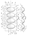
Fig. 1 is a plan view of an ice tray according to one aspect of the present disclosure; -
Fig. 2 is a cross sectional view of the ice tray ofFig. 1 taken along the II-II; -
Fig. 3 is a plan view of an ice tray according to another aspect of the present disclosure; -
Fig. 4 is a cross sectional view of the ice tray ofFig. 3 taken along the line IV-IV; -
Fig. 5 is an isometric view of an ice tray and water supply arrangement according to another aspect of the present disclosure; -
Fig. 6 is an isometric view of an ice tray and water supply arrangement according to another aspect of the present disclosure; -
Fig. 7 is an isometric view of an ice tray and water supply arrangement according to another aspect of the present disclosure; -
Fig. 8 is a schematic view of a freezer including an ice tray, water supply system, and ice cube storage bin according to another aspect of the present disclosure. - For purposes of description herein, the terms "upper," "lower," "right," "left," "rear," "front," "vertical," "horizontal," and derivatives thereof shall relate to the invention as oriented in
Fig. 2 . However, it is to be understood that the invention may assume various alternative orientations and step sequences, except where expressly specified to the contrary. It is also to be understood that the specific devices and processes illustrated in the attached drawings, and described in the following specification, are simply exemplary embodiments of the inventive concepts defined in the appended claims. Hence, specific dimensions and other physical characteristics relating to the embodiments disclosed herein are not to be considered as limiting, unless the claims expressly state otherwise. - With reference to
Figs. 1 and 2 , anice tray 1 according to one aspect of the present invention includes abody portion 2, and a plurality of upwardly openingcavities 4. Thebody portion 2 andcavities 4 are preferably formed from a single piece of sheet metal such as stainless steel, aluminum, or other suitable metal. For example, theice tray 1 may be formed from stainless steel having a thickness of about 0.035 inches to about 0.065 inches. Theice tray 1 may be formed from a flat sheet of metal utilizing known die forming processes or other suitable techniques. Theice tray 1 may also be made from a single piece of molded polymer or other suitable material utilizing a mold or other known processes. - The
body portion 2 generally comprises a thin sheet of material having an upper side 6 and alower side 8.Cavities 4 includeopenings 10 that are defined byedges 12.Cavities 4 are generally formed by upwardly extendingsidewalls 14, and alower wall 16. Thesidewalls 14 andlower wall 16 may be curved, and may blend together, such that the terms "sidewall" and "lower wall" do not necessarily refer to vertical and horizontal walls. Thesidewalls 14 andlower walls 16 form a concaveinner surfaces 18 definingcavities 4. Thesidewalls 14 intersect thebody portion 2 at an angle of about 90° to defineedges 12 extending aroundcavities 4 to defineopenings 10.Edges 12 may have a radius such that the transition from thebody portion 2 to thesidewalls 14 does not form a sharp corner. For example,inner surface 18 ofsidewall 14 may transition toupper surface 20 ofbody portion 2 to define an outer radius of about 0.050-0.100 inches. - The
body portion 2 defines a generally quadrilateral perimeter 28 (Fig. 1 ) having elongatedopposite edges end edges body portion 2 includesregions 26 betweenadjacent cavities 4, andregions 34A betweencavities 4 andelongated edge 30A, andregions 34B betweencavities 4 andelongated edges 30B. Still further,body portion 2 also includesregions outermost cavities 4 andend edges regions ice tray 1 may be twisted about an elongated axis "A" (Fig. 1 ) to assist in removing ice cubes fromcavities 4. Because thebody portion 2 is substantially planar, stress increases that otherwise could occur in the vicinity of channels or weirs extending betweencavities 4 is reduced. The reduced stress helps extend the life ofice tray 1. - With further reference to
Figs. 3 and 4 , anice tray 1A according to another aspect of the present disclosure includes abody portion 2A and a plurality ofcavities 4A. In contrast toice tray 1 ofFigs. 1 and 2 ,ice tray 1A includes a plurality of raisedportions 40 that are generally triangular in plan view (Fig. 3 ).Sidewalls portions 40 extend transversely upward fromupper surface 20A ofbody portion 2A.Inner sidewalls 46 of raisedportions 40 generally facecavities 4, and extend continuously upwardly frominner surfaces 18A ofcavities 4A. - As discussed above in connection with
Figs. 1 and 2 ,ice tray 1 is twisted to remove ice cubes fromcavities 4. Because the body portion 2 (Figs. 1 and 2 ) ofice tray 1 is generally flat, it is relatively flexible with respect to twisting about axis A. However, thesidewalls 14 stiffen thebody portion 2 in the areas directlyadjacent edges 12. This stiffness may cause increased stress in thebody portion 2 in the regions directlyadjacent edges 12. Furthermore, although theedges 12 may be radiused at the transition betweenbody portion 2 andsidewalls 14, the geometry of theedges 12 also tends to cause increased stress at theedges 12. Still further, thecavities 4 are relatively rigid with respect to twisting ofice tray 1 about axis A, such that a significant portion of the deformation and resulting stress from twisting ofice tray 1 tends to occur in theregions 26 ofbody portion 2 betweencavities 4. - Referring again to
Figs. 3 and 4 , the regions ofbody portion 2 where the highest stress concentrations tend to occur correspond to the raisedportions 40. The geometry of the raisedportions 40 reduces the stress concentrations in these regions to thereby extend the life ofice tray 1A. It will be understood that the shape, size, and location of the raisedportions 40 may vary somewhat depending upon the geometry of thecavities 4, the material selected to formice tray 1, the degree of flexing required to release ice cubes fromcavities 4, and other such factors. - As discussed above, the
ice trays adjacent cavities Fig. 5 , awater distribution system 48 includes afluid conduit 50 that receives water from an external source, and distributeswater 52 to a plurality ofopenings 54A-54D that are fluidly connected toindividual conduits 56A-56D, respectively. The fluid distribution system 50A provides a predefined volume of water to eachcavity cavity tray support member 58 to thereby position thetray openings 54A-54D. Theopenings 54A-54D are preferably directly above thecavities openings 54A-54D flows directly into thecavities - With further reference to
Fig. 6 , awater distribution system 48B according to another aspect of the present invention includes afluid supply conduit 60 having anopening 60 that is positioned directly above acavity 62 of atrough 64.Trough 64 includes afront wall 66, arear wall 68, and endwalls bottom wall 72 extends between thewalls cavity 62. However, thetrough 64 could have other shapes (e.g. curved side and bottom walls). A plurality ofopenings 74A-74D in the form of indentations or cut outs infront wall 66 provide for flow of water fromcavity 62 oftrough 64 into thecavities ice tray openings 74A-74D could comprise apertures or other suitable fluid passageways throughfront wall 66 oftrough 64. - With further reference to
Fig. 7 , atrough 64A may include a plurality ofdivider walls 80 forming a plurality ofindividual cavities 62A-62D. Thepartition walls 80 includecutouts 82A-82C that permits flow of water between theindividual cavities 62A-62D. Ashaft 84 rotatably supports thetrough 64A, and a powered actuator such as anelectric motor 86 provides for powered rotation oftrough 64A. In use, water flows through conduit 76, and exits opening 78 of conduit 76 and flows into a selected one of theindividual cavities 62A-62D. The water then flows to adjacent cavities through cutouts 82 individer walls 80. Once a specified amount of water has been introduced into thecavities 62A-62D,electric motor 86 rotates such that the water pours throughopenings 74A-74D infront wall 66A oftrough 64A. - With reference to
Fig. 8 , a refrigerator 90 may include afreezer compartment 92, acontroller 94, and acooling system 96 that is operably connected to thecontroller 94.Water distribution system 98 includes awater supply conduit 100, apowered valve 102, and apump 104. Thevalve 102 and pump 104 are operably connected tocontroller 94, andcontroller 94 thereby controls the amount of water that is supplied to awater distribution system 48. The flow rate of water throughwater distribution system 48 may be determined by testing, and thevalve 102 and/or pump 104 may be actuated for a specific time interval to permit a predefined volume of water to be introduced into eachcavity water distribution system 48 may comprise a water distribution system as disclosed inFig. 5, Fig. 6, or Fig. 7 , or it may comprise another suitable water distribution system. - The
ice tray support 58 in afreezer compartment 92 above anice storage bin 108. After a predetermined amount of water 6 is introduced into each cavity 4 (or 4A), the water freezes to form ice cubes. Adevice 110 is configured to twistice tray ice tray ice storage bin 108 positioned directly below theice tray Device 110 then rotates theice tray cavities water distribution system 48.Device 110 is operably connected tocontroller 94.Device 110 may be substantially similar to known ice harvesting devices that twist and rotate ice cube trays for harvest of the ice cubes, anddevice 110 will therefore not be described in detail herein. It will be understood thatice tray - It is also to be understood that variations and modifications can be made on the aforementioned structures and methods without departing from the scope of the present invention as defined by the following claims.
Claims (15)
- An ice making system, comprising:a weirless ice tray having upper and lower sides, the tray including a body portion and a plurality of upwardly opening cavities that are interconnected by the body portion, each cavity having an upper peripheral edge defining an opening for receiving liquid water to be frozen in the cavity, each cavity defining a cavity volume whereby liquid water in excess of the cavity volume overflows the cavity if introduced into the cavity, wherein the upper peripheral edges do not form weirs between adjacent cavities such that excess liquid water overflowing a cavity does not flow solely into adjacent cavities;a water distribution system configured to introduce a volume of water into each cavity that is no greater than each cavity volume to thereby substantially fill each cavity with liquid water without overflowing the cavities.
- The ice making system of claim 1, wherein:the water distribution system includes a fluid conduit having a plurality of outlets, at least one outlet being positioned above each cavity such that water flowing through the fluid conduit exits the outlets and flows into the cavities.
- The ice making system of claim 2, wherein:the fluid conduit comprises a primary fluid conduit and a plurality of individual conduits extending from the primary fluid conduit to the outlets.
- The ice making system of claim 3, wherein:the cavities form a row of cavities; andthe primary fluid conduit comprises an elongated tubular member extending along the row of cavities.
- The ice making system of claim 2, 3 or 4 wherein:the fluid conduit comprises an upwardly opening trough forming the outlets; andthe fluid conduit further comprises an elongated tubular member that is fluidly connected to the trough to supply water to the trough.
- The ice making system of claim 5, wherein:the trough comprises elongated generally upright front and rear sidewalls and a lower wall extending between the front and rear sidewalls; andthe outlets comprise fluid passageways through the front wall of the trough.
- The ice making system of claim 1, wherein:the water distribution system includes a flow control device;the ice making system includes a controller that is operably connected to the flow control device, wherein the controller actuates the flow control device to introduce a volume of water into each cavity that is no greater than the cavity volumes.
- The ice making system of claim 7, wherein:the flow control device comprises a valve having a powered actuator or comprises an electrically powered pump.
- The ice making system according to any one of the preceding claims, wherein:the body portion comprises a thin sheet of material having substantially planar upper surface portions, optionally wherein:the entire body portion comprises a single planar sheet of metal with a continuous planar upper surface that is free of protrusions.
- The ice making system of claim 9, wherein:the body portion comprises formed sheet metal having upwardly-protruding raised portions disposed between adjacent cavities.
- The ice making system according to any one of the preceding claims, wherein:the ice making system includes an ice storage bin and a powered device that twists and rotates the ice tray to thereby cause ice cubes in the tray to become dislodged and fall into the ice storage bin.
- The ice making system according to any one of the preceding claims, wherein:the openings are oblong or approximately oval in shape in plan view.
- A method of making ice cubes, the method comprising:providing an ice tray having a plurality of upwardly opening cavities, each cavity defining a cavity volume such that the cavities overflow if a volume of water greater than the cavity volume is introduced into the cavities;introducing a volume of water into each cavity, wherein the volumes of water are no greater than the cavity volumes such that the cavities do not overflow; andfreezing the water in the cavities to form ice cubes.
- The method of claim 13, including at least one of:removing ice cubes from the ice tray by twisting the ice tray and rotating the ice tray such that the ice cubes fall out of the cavities; andintroducing the volumes of water by utilizing a fluid conduit having a fluid exit positioned above each cavity.
- The ice making system of any one of claims 1 to 12 or the method of claim 13 or 14, wherein:the cavity volumes and/or the volumes of water are equal to one another.
Applications Claiming Priority (1)
| Application Number | Priority Date | Filing Date | Title |
|---|---|---|---|
| US13/713,271 US9599385B2 (en) | 2012-12-13 | 2012-12-13 | Weirless ice tray |
Publications (2)
| Publication Number | Publication Date |
|---|---|
| EP2743612A2 true EP2743612A2 (en) | 2014-06-18 |
| EP2743612A3 EP2743612A3 (en) | 2017-05-24 |
Family
ID=49709509
Family Applications (1)
| Application Number | Title | Priority Date | Filing Date |
|---|---|---|---|
| EP13194687.3A Withdrawn EP2743612A3 (en) | 2012-12-13 | 2013-11-27 | Weirless ice tray |
Country Status (2)
| Country | Link |
|---|---|
| US (1) | US9599385B2 (en) |
| EP (1) | EP2743612A3 (en) |
Cited By (2)
| Publication number | Priority date | Publication date | Assignee | Title |
|---|---|---|---|---|
| EP3106787A1 (en) * | 2015-06-17 | 2016-12-21 | Dongbu Daewoo Electronics Corporation | Ice tray in an ice making device and method of producing ice |
| WO2018015150A1 (en) * | 2016-07-19 | 2018-01-25 | Arcelik Anonim Sirketi | A freezer device comprising an ice unit producing clear ice |
Families Citing this family (12)
| Publication number | Priority date | Publication date | Assignee | Title |
|---|---|---|---|---|
| KR101723152B1 (en) * | 2015-06-17 | 2017-04-04 | 동부대우전자 주식회사 | Refrigerator and method for supplying water of refrigerator |
| KR200482995Y1 (en) * | 2015-08-19 | 2017-03-23 | 이현진 | Ice tray with water supply part |
| KR102451448B1 (en) * | 2015-12-04 | 2022-10-07 | 삼성전자주식회사 | Ice maker and refrigerator having the same |
| WO2017132047A1 (en) * | 2016-01-29 | 2017-08-03 | Illinois Tool Works, Inc. | Smart ice system |
| EP3438575A1 (en) * | 2017-07-31 | 2019-02-06 | W. Schoonen Beheer B.V. | Efficient clear ice cube production |
| US10697684B2 (en) * | 2018-03-20 | 2020-06-30 | Bsh Home Appliances Corporation | Automatic ice-sphere-making system for refrigerator appliance |
| US10605511B2 (en) * | 2018-05-02 | 2020-03-31 | Bsh Home Appliances Corporation | Clear ice maker assembly for producing clear ice for refrigerator appliance |
| WO2020049606A1 (en) * | 2018-09-03 | 2020-03-12 | 三菱電機株式会社 | Automatic ice maker |
| US11598566B2 (en) * | 2020-04-06 | 2023-03-07 | Electrolux Home Products, Inc. | Revolving ice maker |
| KR20220057215A (en) | 2020-10-29 | 2022-05-09 | 삼성전자주식회사 | Refrigerator |
| KR20230132166A (en) * | 2022-03-08 | 2023-09-15 | 엘지전자 주식회사 | Ice making apparatus and refrigerator |
| KR20240142007A (en) * | 2023-03-21 | 2024-09-30 | 코웨이 주식회사 | Ice making apparatus and ice making water purifier usind the same |
Family Cites Families (157)
| Publication number | Priority date | Publication date | Assignee | Title |
|---|---|---|---|---|
| US1407614A (en) | 1920-09-23 | 1922-02-21 | Kelvinator Corp | Ice pan |
| US2244081A (en) | 1938-03-05 | 1941-06-03 | Gen Motors Corp | Ice cube mechanism |
| US2481525A (en) | 1943-06-09 | 1949-09-13 | Commerical Plastics Company | Ice cube tray |
| US2617269A (en) | 1949-06-17 | 1952-11-11 | Gen Electric | Surface having low adhesion to ice |
| US2757519A (en) | 1954-02-01 | 1956-08-07 | Gen Motors Corp | Ice making apparatus |
| US2846854A (en) | 1954-02-18 | 1958-08-12 | Gen Motors Corp | Ice cube maker |
| US2878659A (en) | 1955-07-15 | 1959-03-24 | Gen Motors Corp | Refrigerating apparatus |
| US3009336A (en) | 1956-09-04 | 1961-11-21 | John R Bayston | Ice making machine |
| US3016719A (en) | 1957-11-25 | 1962-01-16 | Gen Motors Corp | Material for metal surfaces upon which ice adheres |
| US2969654A (en) | 1958-07-17 | 1961-01-31 | Gen Electric | Automatic ice maker |
| US3084678A (en) | 1960-04-15 | 1963-04-09 | Maurice E Lindsay | Internal combustion engine with shifting cylinders |
| US3033008A (en) | 1960-08-16 | 1962-05-08 | Gen Motors Corp | Patterned and coated ice tray |
| US3075360A (en) | 1961-02-06 | 1963-01-29 | Elfving | Thermoelectric heat pump assembly |
| US3046753A (en) | 1961-04-27 | 1962-07-31 | Frank Carapico Sr | Apparatus for producing ice cubes |
| US3144755A (en) | 1961-07-24 | 1964-08-18 | Kattis Theodore | Small block ice making machine |
| US3217511A (en) | 1963-03-26 | 1965-11-16 | Gen Motors Corp | Ice block harvesting arrangement |
| DE1250457B (en) | 1964-05-22 | 1967-09-21 | Borg-Warner Corporation, Chicago, 111. (V. St. A.) | Thermoelectric piece ice maker |
| US3308631A (en) * | 1964-06-01 | 1967-03-14 | Gen Motors Corp | Flexible tray ice maker |
| US3306064A (en) * | 1965-03-29 | 1967-02-28 | Dole Valve Co | Switch actuator assembly for an ice maker |
| US3318105A (en) | 1965-09-30 | 1967-05-09 | Borg Warner | Method and apparatus for producing clear ice under quiescent conditions |
| US3321932A (en) | 1965-10-21 | 1967-05-30 | Raymond C Stewart | Ice cube tray for producing substantially clear ice cubes |
| US3383876A (en) | 1966-05-31 | 1968-05-21 | Whirlpool Co | Method of harvesting ice bodies and apparatus therefor |
| US3806077A (en) | 1972-06-01 | 1974-04-23 | Gen Motors Corp | Ejector spillguard ice cube tray |
| US3775992A (en) | 1972-07-17 | 1973-12-04 | Gen Motors Corp | Method and apparatus for making clear ice |
| US3864933A (en) | 1973-11-29 | 1975-02-11 | Gen Motors Corp | Defrost timer arrangement for making clear ice |
| US3892105A (en) | 1974-10-21 | 1975-07-01 | Gen Motors Corp | Harvesting apparatus for automatic ice maker |
| US3952539A (en) | 1974-11-18 | 1976-04-27 | General Motors Corporation | Water tray for clear ice maker |
| US3985114A (en) | 1975-05-19 | 1976-10-12 | Alto Automotive, Inc. | Apparatus for shock mounting of piston rods in internal combustion engines and the like |
| US4006605A (en) | 1975-06-16 | 1977-02-08 | King-Seeley Thermos Co. | Ice making machine |
| US4059970A (en) | 1976-10-15 | 1977-11-29 | General Electric Company | Automatic icemaker including means for minimizing the supercooling effect |
| US4062201A (en) | 1976-10-15 | 1977-12-13 | General Electric Company | Automatic icemaker including means for minimizing the supercooling effect |
| DE2647541C3 (en) | 1976-10-21 | 1979-11-08 | Theo 6751 Mackenbach Wessa | Method and device for producing clear small ice cubes |
| US4261182A (en) | 1978-10-05 | 1981-04-14 | General Electric Company | Automatic icemaker including means for minimizing the supercooling effect |
| US4222547A (en) | 1979-01-12 | 1980-09-16 | Lalonde Michael G | Ice tray |
| US4462345A (en) | 1981-07-13 | 1984-07-31 | Pulsar Corporation | Energy transfer device utilizing driveshaft having continuously variable inclined track |
| US4483153A (en) | 1983-02-02 | 1984-11-20 | Emhart Industries, Inc. | Wide island air defrost refrigerated display case having a defrost-only center passage |
| US4587810A (en) | 1984-07-26 | 1986-05-13 | Clawson Machine Company, Inc. | Thermoelectric ice maker with plastic bag mold |
| US4685304A (en) | 1986-02-13 | 1987-08-11 | Essig Robert A | Method and apparatus for forming cube of frozen liquid |
| US4727720A (en) | 1986-04-21 | 1988-03-01 | Wernicki Paul F | Combination ice mold and ice extractor |
| US4856463A (en) | 1987-01-28 | 1989-08-15 | Johnston Richard P | Variable-cycle reciprocating internal combustion engine |
| JPS6435375U (en) * | 1987-08-25 | 1989-03-03 | ||
| US4852359A (en) | 1988-07-27 | 1989-08-01 | Manzotti Ermanno J | Process and apparatus for making clear ice cubes |
| US4843827A (en) | 1988-10-28 | 1989-07-04 | Peppers James M | Method and apparatus for making ice blocks |
| US5129237A (en) | 1989-06-26 | 1992-07-14 | Servend International, Inc. | Ice making machine with freeze and harvest control |
| US5196127A (en) | 1989-10-06 | 1993-03-23 | Zev Solell | Ice cube tray with cover |
| JP2609741B2 (en) | 1990-04-26 | 1997-05-14 | 株式会社東芝 | Refrigerator with automatic ice maker |
| US5025756A (en) | 1990-08-20 | 1991-06-25 | Wladimir Nyc | Internal combustion engine |
| US5044600A (en) | 1991-01-24 | 1991-09-03 | Shannon Steven L | Ice cube dispenser |
| US5157929A (en) | 1991-08-21 | 1992-10-27 | Hotaling William E | Method for producing clear and patterned ice products |
| JPH0611219A (en) | 1992-06-25 | 1994-01-21 | Matsushita Refrig Co Ltd | Automatic ice maker |
| US5425243A (en) | 1992-08-05 | 1995-06-20 | Hoshizaki Denki Kabushiki Kaisha | Mechanism for detecting completion of ice formation in ice making machine |
| US5289691A (en) | 1992-12-11 | 1994-03-01 | The Manitowoc Company, Inc. | Self-cleaning self-sterilizing ice making machine |
| US5257601A (en) | 1993-02-01 | 1993-11-02 | Coffin David F | Adjustable rotary valve assembly for a combustion engine |
| US5408844A (en) | 1994-06-17 | 1995-04-25 | General Electric Company | Ice maker subassembly for a refrigerator freezer |
| US5483929A (en) | 1994-07-22 | 1996-01-16 | Kuhn-Johnson Design Group, Inc. | Reciprocating valve actuator device |
| US6282909B1 (en) | 1995-09-01 | 2001-09-04 | Nartron Corporation | Ice making system, method, and component apparatus |
| NO303190B1 (en) | 1996-07-04 | 1998-06-08 | Dag F Lilleaas | Process for making ice cubes and machine for making the same |
| JPH10227547A (en) | 1997-02-13 | 1998-08-25 | Sanyo Electric Co Ltd | Controller for operation of ice making machine |
| US5884490A (en) | 1997-03-25 | 1999-03-23 | Whidden; William L. | Method and apparatus producing clear ice objects utilizing flexible molds having internal roughness |
| US5878583A (en) | 1997-04-01 | 1999-03-09 | Manitowoc Foodservice Group, Inc. | Ice making machine and control method therefore |
| JPH11223434A (en) | 1998-02-05 | 1999-08-17 | Sanyo Electric Co Ltd | Ice machine |
| JP2000039240A (en) | 1998-07-21 | 2000-02-08 | Hoshizaki Electric Co Ltd | Ice making machine |
| US6209849B1 (en) | 1998-12-23 | 2001-04-03 | H & D Product Development, Llc | Ice cube tray |
| US6101817A (en) | 1999-04-06 | 2000-08-15 | Watt; John R. | Method and apparatus for continuously extruding ice |
| JP3574011B2 (en) | 1999-07-30 | 2004-10-06 | 三洋電機株式会社 | Ice making apparatus and refrigerator-freezer provided with the same |
| JP2001041624A (en) | 1999-07-30 | 2001-02-16 | Sanyo Electric Co Ltd | Ice maker and deep freezer refrigerator having the same |
| JP2001355946A (en) * | 2000-04-10 | 2001-12-26 | Sanyo Electric Co Ltd | Ice plant and freezing refrigerator equipped with it |
| SE522629C2 (en) | 2000-06-05 | 2004-02-24 | Volvo Lastvagnar Ab | Apparatus for controlling the phase angle between a first and a second crankshaft |
| KR100389389B1 (en) | 2000-08-07 | 2003-06-27 | 주식회사 엘지이아이 | The ice-making unit for refrigerators |
| GB0020964D0 (en) | 2000-08-25 | 2000-10-11 | Reckitt & Colmann Prod Ltd | Improvements in or relating to containers |
| CN1455856A (en) | 2000-09-01 | 2003-11-12 | 素村胜三 | Method and apparatus for producing stereoscopic ice of transparent sphere or the like |
| JP2002139268A (en) | 2000-10-31 | 2002-05-17 | Sanyo Electric Co Ltd | Ice maker and freezer/refrigerator comprising it |
| US6782706B2 (en) | 2000-12-22 | 2004-08-31 | General Electric Company | Refrigerator—electronics architecture |
| JP2002295934A (en) | 2001-03-30 | 2002-10-09 | Fuji Electric Co Ltd | Ice machine control device |
| US6357720B1 (en) | 2001-06-19 | 2002-03-19 | General Electric Company | Clear ice tray |
| JP2003042612A (en) | 2001-07-26 | 2003-02-13 | Sanyo Electric Co Ltd | Ice making device and refrigerator-freezer equipped therewith |
| JP2003042621A (en) | 2001-07-31 | 2003-02-13 | Fukushima Industries Corp | Ice machine |
| JP2003172564A (en) | 2001-12-06 | 2003-06-20 | Sanyo Electric Co Ltd | Ice-making device, and refrigerator-freezer having the device |
| DE10162917A1 (en) | 2001-12-20 | 2003-07-03 | Bsh Bosch Siemens Hausgeraete | ice maker |
| JP2003232587A (en) | 2002-02-08 | 2003-08-22 | Matsushita Electric Ind Co Ltd | Ice making equipment |
| JP2003269830A (en) | 2002-03-19 | 2003-09-25 | Sanyo Electric Co Ltd | refrigerator |
| JP2003279214A (en) | 2002-03-20 | 2003-10-02 | Sanyo Electric Co Ltd | Ice making device and refrigerator provided with this ice making device |
| JP2002350019A (en) | 2002-04-10 | 2002-12-04 | Matsushita Refrig Co Ltd | Method for making transparent ice |
| US6935124B2 (en) | 2002-05-30 | 2005-08-30 | Matsushita Electric Industrial Co., Ltd. | Clear ice making apparatus, clear ice making method and refrigerator |
| JP2004053036A (en) | 2002-07-16 | 2004-02-19 | Matsushita Refrig Co Ltd | Transparent ice making device and transparent ice making method |
| KR20040039091A (en) | 2002-10-31 | 2004-05-10 | 히데오 나까조 | Ice making machine |
| KR20040039089A (en) | 2002-10-31 | 2004-05-10 | 삼성광주전자 주식회사 | Ice making machine |
| KR20040039090A (en) | 2002-10-31 | 2004-05-10 | 삼성광주전자 주식회사 | Ice making machine |
| KR20040039092A (en) | 2002-10-31 | 2004-05-10 | 히데오 나까조 | Ice making machine |
| US6951113B1 (en) | 2003-01-14 | 2005-10-04 | Joseph R. Adamski | Variable rate and clarity ice making apparatus |
| WO2004081470A1 (en) | 2003-03-11 | 2004-09-23 | Matsushita Electric Industrial Co., Ltd. | Ice-making device |
| JP2004278894A (en) | 2003-03-14 | 2004-10-07 | Matsushita Electric Ind Co Ltd | Ice making equipment |
| JP2004278990A (en) | 2003-03-18 | 2004-10-07 | Matsushita Electric Ind Co Ltd | Automatic ice making equipment for transparent ice |
| US6735959B1 (en) | 2003-03-20 | 2004-05-18 | General Electric Company | Thermoelectric icemaker and control |
| US7062925B2 (en) | 2003-06-24 | 2006-06-20 | Hoshizaki Denki Kabushiki Kaisha | Method of operating auger icemaking machine |
| US7082782B2 (en) | 2003-08-29 | 2006-08-01 | Manitowoc Foodservice Companies, Inc. | Low-volume ice making machine |
| US7062936B2 (en) | 2003-11-21 | 2006-06-20 | U-Line Corporation | Clear ice making refrigerator |
| JP2005164145A (en) | 2003-12-03 | 2005-06-23 | Matsushita Electric Ind Co Ltd | Ice making equipment |
| JP2005195315A (en) | 2003-12-09 | 2005-07-21 | Matsushita Electric Ind Co Ltd | Ice making equipment and refrigerator |
| US7216490B2 (en) | 2003-12-15 | 2007-05-15 | General Electric Company | Modular thermoelectric chilling system |
| KR20050077583A (en) | 2004-01-28 | 2005-08-03 | 삼성전자주식회사 | Ice manufacture apparatus |
| MXPA04003411A (en) | 2004-04-07 | 2005-10-11 | Mabe De Mexico S De R L De C V | Device for making ice in refrigerated cabinets. |
| JP2006022980A (en) | 2004-07-06 | 2006-01-26 | Matsushita Electric Ind Co Ltd | Ice making equipment |
| US7013654B2 (en) | 2004-07-21 | 2006-03-21 | Emerson Electric Company | Method and device for eliminating connecting webs between ice cubes |
| US8336327B2 (en) | 2004-07-21 | 2012-12-25 | Nidec Motor Corporation | Method and device for producing ice having a harvest-facilitating shape |
| US7415833B2 (en) | 2004-08-06 | 2008-08-26 | Imi Cornelius Inc. | Control system for icemaker for ice and beverage dispenser |
| US7188479B2 (en) | 2004-10-26 | 2007-03-13 | Whirlpool Corporation | Ice and water dispenser on refrigerator compartment door |
| US7131280B2 (en) * | 2004-10-26 | 2006-11-07 | Whirlpool Corporation | Method for making ice in a compact ice maker |
| US7216491B2 (en) * | 2005-04-29 | 2007-05-15 | Emerson Electric Co | Ice maker with adaptive fill |
| US7284390B2 (en) | 2005-05-18 | 2007-10-23 | Whirlpool Corporation | Refrigerator with intermediate temperature icemaking compartment |
| JP2006323704A (en) | 2005-05-19 | 2006-11-30 | Hitachi Communication Technologies Ltd | Reporting system |
| US7607312B2 (en) | 2005-05-27 | 2009-10-27 | Maytag Corporation | Insulated ice compartment for bottom mount refrigerator with temperature control system |
| US7234423B2 (en) | 2005-08-04 | 2007-06-26 | Lindsay Maurice E | Internal combustion engine |
| US20070107447A1 (en) * | 2005-11-14 | 2007-05-17 | Langlotz Bennet K | Sealed water-filled container with ice cube features |
| KR100786075B1 (en) | 2005-12-16 | 2007-12-17 | 엘지전자 주식회사 | How to control the operation of the refrigerator |
| US7681406B2 (en) | 2006-01-13 | 2010-03-23 | Electrolux Home Products, Inc. | Ice-making system for refrigeration appliance |
| US7587905B2 (en) | 2006-02-15 | 2009-09-15 | Maytag Corporation | Icemaker system for a refrigerator |
| ES2315996T3 (en) | 2006-02-17 | 2009-04-01 | Vestel Beyaz Esya Sanayi Ve Ticaret A.S. | FAST MANUFACTURE UNIT OF ICE. |
| US20070227162A1 (en) | 2006-04-03 | 2007-10-04 | Ching-Hsiang Wang | Icemaker |
| US7703292B2 (en) | 2006-07-28 | 2010-04-27 | General Electric Company | Apparatus and method for increasing ice production rate |
| EP1918663B1 (en) | 2006-10-31 | 2010-09-15 | Electrolux Home Products Corporation N.V. | Device and method for automatically producing clear ice, and refrigerator featuring such a device |
| US20080104991A1 (en) | 2006-11-03 | 2008-05-08 | Hoehne Mark R | Ice cube tray evaporator |
| WO2008061179A2 (en) | 2006-11-15 | 2008-05-22 | Tiax Llc | Devices and methods for making ice |
| US7614244B2 (en) | 2006-12-21 | 2009-11-10 | General Electric Company | Ice producing apparatus and method |
| US20100031675A1 (en) | 2006-12-28 | 2010-02-11 | Lg Electronics Inc. | Ice making system and method for ice making of refrigerator |
| KR100833860B1 (en) | 2006-12-31 | 2008-06-02 | 엘지전자 주식회사 | Ice maker and control method |
| WO2008085920A2 (en) | 2007-01-05 | 2008-07-17 | Efficient-V, Inc. | Motion translation mechanism |
| DE202007006732U1 (en) | 2007-01-26 | 2008-06-05 | Liebherr-Hausgeräte Ochsenhausen GmbH | Fridge and / or freezer |
| BRPI0700975A (en) | 2007-02-05 | 2008-09-23 | Whirlpool Sa | ice maker |
| KR20090019322A (en) | 2007-08-20 | 2009-02-25 | 엘지전자 주식회사 | Ice maker and refrigerator using the same |
| DE202007014786U1 (en) | 2007-10-23 | 2009-03-05 | Liebherr-Hausgeräte Lienz Gmbh | Ice cube tray and refrigerator and / or freezer with such an ice cube tray |
| KR100928940B1 (en) | 2007-12-05 | 2009-11-30 | 엘지전자 주식회사 | Refrigerator ice maker |
| US20090165492A1 (en) | 2007-12-28 | 2009-07-02 | Mark Wayne Wilson | Icemaker combination assembly |
| US8037697B2 (en) * | 2008-01-09 | 2011-10-18 | Whirlpool Corporation | Refrigerator with an automatic compact fluid operated icemaker |
| US20090187280A1 (en) | 2008-01-22 | 2009-07-23 | Hsu Shih-Hsien | Method for controlling ice machine through temperature setting |
| KR101387790B1 (en) | 2008-02-27 | 2014-04-21 | 엘지전자 주식회사 | Ice making assembly for a refrigerator and method for sensing a water level thereof |
| US20090211266A1 (en) | 2008-02-27 | 2009-08-27 | Young Jin Kim | Method of controlling ice making assembly for refrigerator |
| KR101457691B1 (en) | 2008-03-10 | 2014-11-03 | 엘지전자 주식회사 | Controlling method of an ice making assembly for refrigerator |
| US20090235674A1 (en) | 2008-03-19 | 2009-09-24 | Jeffrey Kern | Demand driven ice mode software |
| US20090308085A1 (en) | 2008-06-12 | 2009-12-17 | General Electric Company | Rotating icemaker assembly |
| CA2723051C (en) | 2008-09-15 | 2016-12-06 | General Electric Company | Energy management of dishwasher appliance |
| KR101570349B1 (en) | 2008-11-21 | 2015-11-19 | 엘지전자 주식회사 | Refrigerator |
| US8429926B2 (en) | 2009-01-22 | 2013-04-30 | General Electric Company | Ice storage bin and icemaker apparatus for refrigerator |
| US8413619B2 (en) | 2010-10-08 | 2013-04-09 | Pinnacle Engines, Inc. | Variable compression ratio systems for opposed-piston and other internal combustion engines, and related methods of manufacture and use |
| KR101688133B1 (en) * | 2009-06-22 | 2016-12-20 | 엘지전자 주식회사 | Ice maker and refrigerator having the same and ice making method thereof |
| US8171744B2 (en) | 2009-06-30 | 2012-05-08 | General Electric Company | Method and apparatus for controlling temperature for forming ice within an icemaker compartment of a refrigerator |
| JP5484187B2 (en) | 2009-09-24 | 2014-05-07 | 日本電産サンキョー株式会社 | Ice making equipment |
| DE102009046030A1 (en) * | 2009-10-27 | 2011-04-28 | BSH Bosch und Siemens Hausgeräte GmbH | Refrigerating appliance and ice maker for it |
| US8769981B2 (en) | 2009-12-22 | 2014-07-08 | Lg Electronics Inc. | Refrigerator with ice maker and ice level sensor |
| JP2011158110A (en) | 2010-01-29 | 2011-08-18 | Nidec Sankyo Corp | Method of making ice, and ice making device |
| US9217596B2 (en) | 2010-04-28 | 2015-12-22 | Electrolux Home Products, Inc. | Mechanism for ice creation |
| US20120023996A1 (en) | 2010-07-28 | 2012-02-02 | Herrera Carlos A | Twist tray ice maker system |
| US8746204B2 (en) | 2010-09-29 | 2014-06-10 | Ecomotors, Inc. | Frictionless rocking joint |
| KR101775403B1 (en) | 2011-01-10 | 2017-09-07 | 삼성전자주식회사 | Ice maker and refrigerator having the same |
| CN102353193B (en) | 2011-09-02 | 2013-07-03 | 合肥美的荣事达电冰箱有限公司 | Ice maker and refrigerator |
| US9903631B2 (en) | 2012-04-20 | 2018-02-27 | Bsh Home Appliances Corporation | Refrigerator and ice making device for producing and releasing clear ice, and method thereof |
| US9587871B2 (en) * | 2012-05-03 | 2017-03-07 | Whirlpool Corporation | Heater-less ice maker assembly with a twistable tray |
-
2012
- 2012-12-13 US US13/713,271 patent/US9599385B2/en active Active
-
2013
- 2013-11-27 EP EP13194687.3A patent/EP2743612A3/en not_active Withdrawn
Non-Patent Citations (1)
| Title |
|---|
| None |
Cited By (4)
| Publication number | Priority date | Publication date | Assignee | Title |
|---|---|---|---|---|
| EP3106787A1 (en) * | 2015-06-17 | 2016-12-21 | Dongbu Daewoo Electronics Corporation | Ice tray in an ice making device and method of producing ice |
| CN106257171A (en) * | 2015-06-17 | 2016-12-28 | 东部大宇电子株式会社 | Ice pan in ice making equipment and the method for generation ice |
| CN106257171B (en) * | 2015-06-17 | 2019-03-15 | 东部大宇电子株式会社 | The method of ice pan and generation ice in ice making equipment |
| WO2018015150A1 (en) * | 2016-07-19 | 2018-01-25 | Arcelik Anonim Sirketi | A freezer device comprising an ice unit producing clear ice |
Also Published As
| Publication number | Publication date |
|---|---|
| US20140165623A1 (en) | 2014-06-19 |
| US9599385B2 (en) | 2017-03-21 |
| EP2743612A3 (en) | 2017-05-24 |
Similar Documents
| Publication | Publication Date | Title |
|---|---|---|
| US9599385B2 (en) | Weirless ice tray | |
| EP2733445B1 (en) | Ice cube release system and method | |
| US10260789B2 (en) | Ice making assembly with twist ice tray and directional cooling | |
| US9869503B1 (en) | Tray for forming frozen solids | |
| US20120324916A1 (en) | Clear ice making system and method | |
| EP2584293A3 (en) | Ice bucket for unlaying ice curdling | |
| US20160298892A1 (en) | Flow-down type ice making machine and method of manufacturing ice making rack of the flow-down type ice making machine | |
| US9989292B2 (en) | Ice cube manipulation via heat | |
| CN102803872B (en) | Refrigeration device and corresponding ice maker | |
| KR100714559B1 (en) | Ice Tray Assembly For Refrigerator | |
| US3620497A (en) | Parallelogram ice tray cavity | |
| CN102597662B (en) | With the refrigerating appliance of ice maker | |
| KR102129537B1 (en) | Ice making device and method by the same | |
| US9638451B2 (en) | Clad metal ice cube tray | |
| EP3290831B1 (en) | Ice making assembly with twist ice tray and directional defrost | |
| EP3643995B1 (en) | Ice maker with a downspout | |
| JP6510352B2 (en) | Ice maker | |
| WO2002052207A1 (en) | Refrigerator | |
| US9593874B2 (en) | Ice mold for bottleneck | |
| KR101547223B1 (en) | Apparatus for manufacturing iced bar of circle type | |
| WO2017211407A1 (en) | Ice maker for use in a refrigerator | |
| JPH1030864A (en) | Ice tray and ice making method | |
| JP5939844B2 (en) | Ice tray, automatic ice maker, and refrigerator | |
| JP6517120B2 (en) | Ice maker | |
| US12590746B2 (en) | Refrigerator and ice making assembly for producing high-quality ice |
Legal Events
| Date | Code | Title | Description |
|---|---|---|---|
| PUAI | Public reference made under article 153(3) epc to a published international application that has entered the european phase |
Free format text: ORIGINAL CODE: 0009012 |
|
| 17P | Request for examination filed |
Effective date: 20131127 |
|
| AK | Designated contracting states |
Kind code of ref document: A2 Designated state(s): AL AT BE BG CH CY CZ DE DK EE ES FI FR GB GR HR HU IE IS IT LI LT LU LV MC MK MT NL NO PL PT RO RS SE SI SK SM TR |
|
| AX | Request for extension of the european patent |
Extension state: BA ME |
|
| PUAL | Search report despatched |
Free format text: ORIGINAL CODE: 0009013 |
|
| AK | Designated contracting states |
Kind code of ref document: A3 Designated state(s): AL AT BE BG CH CY CZ DE DK EE ES FI FR GB GR HR HU IE IS IT LI LT LU LV MC MK MT NL NO PL PT RO RS SE SI SK SM TR |
|
| AX | Request for extension of the european patent |
Extension state: BA ME |
|
| RIC1 | Information provided on ipc code assigned before grant |
Ipc: F25C 1/24 20060101AFI20170418BHEP Ipc: F25C 1/22 20060101ALI20170418BHEP |
|
| STAA | Information on the status of an ep patent application or granted ep patent |
Free format text: STATUS: REQUEST FOR EXAMINATION WAS MADE |
|
| 18D | Application deemed to be withdrawn |
Effective date: 20171125 |