EP1918663B1 - Device and method for automatically producing clear ice, and refrigerator featuring such a device - Google Patents
Device and method for automatically producing clear ice, and refrigerator featuring such a device Download PDFInfo
- Publication number
- EP1918663B1 EP1918663B1 EP06123270A EP06123270A EP1918663B1 EP 1918663 B1 EP1918663 B1 EP 1918663B1 EP 06123270 A EP06123270 A EP 06123270A EP 06123270 A EP06123270 A EP 06123270A EP 1918663 B1 EP1918663 B1 EP 1918663B1
- Authority
- EP
- European Patent Office
- Prior art keywords
- tray
- water
- ice
- longitudinal axis
- cooling
- Prior art date
- Legal status (The legal status is an assumption and is not a legal conclusion. Google has not performed a legal analysis and makes no representation as to the accuracy of the status listed.)
- Not-in-force
Links
Images


Classifications
-
- F—MECHANICAL ENGINEERING; LIGHTING; HEATING; WEAPONS; BLASTING
- F25—REFRIGERATION OR COOLING; COMBINED HEATING AND REFRIGERATION SYSTEMS; HEAT PUMP SYSTEMS; MANUFACTURE OR STORAGE OF ICE; LIQUEFACTION SOLIDIFICATION OF GASES
- F25C—PRODUCING, WORKING OR HANDLING ICE
- F25C1/00—Producing ice
- F25C1/18—Producing ice of a particular transparency or translucency, e.g. by injecting air
- F25C1/20—Producing ice of a particular transparency or translucency, e.g. by injecting air by agitation
-
- F—MECHANICAL ENGINEERING; LIGHTING; HEATING; WEAPONS; BLASTING
- F25—REFRIGERATION OR COOLING; COMBINED HEATING AND REFRIGERATION SYSTEMS; HEAT PUMP SYSTEMS; MANUFACTURE OR STORAGE OF ICE; LIQUEFACTION SOLIDIFICATION OF GASES
- F25C—PRODUCING, WORKING OR HANDLING ICE
- F25C1/00—Producing ice
- F25C1/10—Producing ice by using rotating or otherwise moving moulds
-
- F—MECHANICAL ENGINEERING; LIGHTING; HEATING; WEAPONS; BLASTING
- F25—REFRIGERATION OR COOLING; COMBINED HEATING AND REFRIGERATION SYSTEMS; HEAT PUMP SYSTEMS; MANUFACTURE OR STORAGE OF ICE; LIQUEFACTION SOLIDIFICATION OF GASES
- F25C—PRODUCING, WORKING OR HANDLING ICE
- F25C2400/00—Auxiliary features or devices for producing, working or handling ice
- F25C2400/10—Refrigerator units
Definitions
- the present invention relates to a device and method for producing clear ice, and to a refrigerator featuring such a device.
- the present invention relates to a household refrigerator featuring a fast-operating device for producing clear ice, i.e. ice of extremely low opacity, to which the following description refers purely by way of example.
- Household refrigerators are known which are fitted inside with an ice-making device normally comprising a water/ice tray inside the refrigerator; a device for feeding a given amount of water into the tray; and a cooling device comprising an evaporator located at the tray to appropriately cool/freeze the water in the tray and convert it into ice.
- an ice-making device normally comprising a water/ice tray inside the refrigerator; a device for feeding a given amount of water into the tray; and a cooling device comprising an evaporator located at the tray to appropriately cool/freeze the water in the tray and convert it into ice.
- Some ice-making devices of the type described above also feature a drive unit for appropriately moving the tray to move the water/ice in the tray as the water is cooling. Moving the water in the tray as it is cooling/freezing, in fact, is known to remove and/or separate air bubbles and/or salts in the water to produce clearer ice.
- Japanese Patent JP 2001221543 describes an ice-making device with a drive unit for rotating the water tray about the longitudinal axis of the tray, so as to move the water in the tray as it is cooling.
- EP0794397 discloses a device operating the stirrer and the cup for containing the water in a machine for the production of ice cubes.
- the device comprises a single motor that gives motion to a first rotating shaft operated in a continuous manner and to a second rotating shaft operated in a discontinuous manner.
- the first rotating shaft is connected to the stirrer by first motion transmission means suitable for converting the rotation of said first shaft into an alternating oscillatory movement of the stirrer.
- the second rotating shaft is in turn connected to the bowl of water by second motion transmission means suitable for converting the rotation of said second shaft into a corresponding motion of tipping the bowl over.
- the present invention is substantially based on the principle of oscillating a water tray about a respective longitudinal axis as the water in the tray is cooling; and creating specific turbulent motion of the water/ice in the tray by means of fins or paddles mounted firmly to the bottom of the tray and parallel to the longitudinal axis.
- the paddles in fact, advantageously produce rapid movement of the water/ice in the tray in the current oscillation direction, to separate air bubbles and/or salts from the ice more effectively than known devices.
- Number 1 in Figure 1 indicates as a whole a preferably, though not necessarily, household refrigerator (shown only partly for the sake of clarity) comprising, inside, one or more refrigeration compartments 2.
- Refrigerator 1 comprises a fast-operating device 3 for producing clear ice, and which is housed inside one of refrigeration compartments 2 of the refrigerator - preferably, though not necessarily, the fresh-food compartment.
- Device 3 substantially comprises a box-shaped container 4; a water and ice-forming tray 5 fitted to container 4 to rotate freely about a respective longitudinal axis A; and a drive unit 6, which, on command, rotates tray 5 back and forth in opposite rotation directions about longitudinal axis A to produce a predetermined oscillating movement of tray 5 about longitudinal axis A.
- Device 3 also comprises a cooling device 7 located inside refrigeration compartment 2, at tray 5, to cool the water in tray 5; and a feed device 8 for feeding water into tray 5.
- feed device 8 comprises a water tank 9; a feed conduit 10 connecting tank 9 to tray 5; and a pump 11 located along feed conduit 10 to pump water, on command, from tank 9 into tray 5 along feed conduit 10.
- Feed device 8 is known and therefore not described in detail.
- tray 5 has a substantially semicircular cross section, crosswise to longitudinal axis A, and comprises a bottom wall 5a extending along longitudinal axis A; and two lateral walls 5b extending crosswise to longitudinal axis A and defining the ends of tray 5.
- tray 5 of device 3 comprises a number of longitudinal fins or paddles 12 fixed rigidly to bottom wall 5a and extending parallel to longitudinal axis A. More specifically, paddles 12 are spaced apart and project radially from the inner surface of bottom wall 5a.
- tray 5 location of longitudinal paddles 12 inside tray 5 is extremely advantageous in forcibly moving, and so effectively agitating, the water in tray 5 as tray 5 oscillates about axis A.
- tray 5 rotates, paddles 12 draw along a given amount of water between them at high speed, i.e. at the same speed at which tray 5 oscillates, whereas the rest of the water, not located between paddles 12, moves at a slower speed.
- the difference between the two speeds advantageously produces in tray 5 a number of streams of water flowing at different speeds, and which enhance separation of air bubbles and salts from the ice.
- Drive unit 6 comprises an electric motor 13; and a transmission mechanism 14 for transmitting the oscillating movement generated by electric motor 13 on its output shaft to tray 5.
- electric motor 13 is controlled by an electric control unit 15 which, at predetermined intervals, changes the rotation direction of the output shaft of electric motor 13 to produce an oscillating movement of tray 5.
- Electric unit 15 may obviously comprise a number of position sensors (not shown) for communicating the position of tray 5 to electric unit 15, which, in this case, could control the change in the rotation direction of the motion produced by electric motor 13 as a function of the angular position of tray 5.
- Transmission mechanism 14 may comprise a system of gears (not shown) meshing with one another to transmit the motion produced by electric motor 13 on its output shaft to a rotation pin 5c fixed to lateral wall 5b of tray 5 and coaxial with longitudinal axis A.
- cooling device 7 comprises an evaporator, which is appropriately connected to a compression and condensing circuit (not shown), is housed inside container 4 and/or refrigeration compartment 2 of refrigerator 1, and is positioned facing the opening of tray 5 to freeze the water in tray 5 into ice.
- Cooling device 7 comprises a finger evaporator, in turn comprising a coolant circulating conduit 18, which, in the Figure 1 example, has two parallel branches 19 directly facing the opening of tray 5; and a number of ice-forming fingers or projecting members 20 extending from conduit 18 towards tray 5 and immersed in the water in the tray.
- the two branches 19 are series-connected, have a coolant inlet 18a and outlet 18b, and extend parallel to longitudinal axis A; whereas the ice-forming fingers or projecting members 20 project from respective branches 19, in a direction substantially crosswise to longitudinal axis A, into the space inside tray 5 and towards bottom wall 5a.
- feed device 8 feeds water into tray 5.
- control unit 15 activates electric motor 15 to oscillate tray 5 about longitudinal axis A, and, at the same time, activates cooling of the coolant of the evaporator which in turn cools/freezes the water surrounding projecting members 20.
- the evaporator As the tray oscillates, the evaporator remains in a predetermined position, i.e. stationary with respect to tray 5, which, as it oscillates, produces a relative movement between the water/ice inside it, which tends to move in the current oscillation direction, and projecting members 20 of the evaporator, which are bathed repeatedly by the water/ice.
- the turbulent motion so formed improves separation of air bubbles and salts from the ice, thus making the ice clearer and more transparent.
- the ice-making method therefore substantially comprises the steps of:
- tray 5 is rotated by electric motor 13 back and forth to oscillate about axis A. And, as tray 5 oscillates, paddles 12 move a given amount of water back and forth, in the two opposite rotation directions, at a faster speed than the rest of the water in the tray not located between the paddles 12, so as to effectively stir the water/ice and achieve the formation of extremely clear, transparent ice.
- the device described above is extremely advantageous, by virtue of paddles 12 on bottom wall 5a of tray 5 producing rapid movement of the water in tray 5, and hence turbulent motion which provides for obtaining clearer, more transparent ice than that produced by known ice-making devices.
Abstract
Description
- The present invention relates to a device and method for producing clear ice, and to a refrigerator featuring such a device.
- More specifically, the present invention relates to a household refrigerator featuring a fast-operating device for producing clear ice, i.e. ice of extremely low opacity, to which the following description refers purely by way of example.
- Household refrigerators are known which are fitted inside with an ice-making device normally comprising a water/ice tray inside the refrigerator; a device for feeding a given amount of water into the tray; and a cooling device comprising an evaporator located at the tray to appropriately cool/freeze the water in the tray and convert it into ice.
- Some ice-making devices of the type described above also feature a drive unit for appropriately moving the tray to move the water/ice in the tray as the water is cooling. Moving the water in the tray as it is cooling/freezing, in fact, is known to remove and/or separate air bubbles and/or salts in the water to produce clearer ice.
-
Japanese Patent JP 2001221543 - Though efficient, the transparency and clarity of the ice produced by the above devices fail to fully meet user demand.
-
EP0794397 discloses a device operating the stirrer and the cup for containing the water in a machine for the production of ice cubes. The device comprises a single motor that gives motion to a first rotating shaft operated in a continuous manner and to a second rotating shaft operated in a discontinuous manner. The first rotating shaft is connected to the stirrer by first motion transmission means suitable for converting the rotation of said first shaft into an alternating oscillatory movement of the stirrer. The second rotating shaft is in turn connected to the bowl of water by second motion transmission means suitable for converting the rotation of said second shaft into a corresponding motion of tipping the bowl over. - It is an object of the present invention to provide a device and method for producing ice of greater transparency and clarity than that produced by known ice-making devices.
- According to the present invention, there are provided a device and method for producing clear ice, as defined in the accompanying Claims.
- A non-limiting embodiment of the present invention will be described by way of example with reference to the accompanying drawings, in which:
-
Figure 1 shows schematically, with parts in section and parts removed for clarity, a portion of a refrigerator featuring an ice-making device for producing clear ice, in accordance with the teachings of the present invention; -
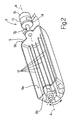
Figure 2 shows a schematic view in perspective of a tray of the ice-making device of theFigure 1 refrigerator; -
Figure 3 shows a cross section of theFigure 2 tray; -
Figures 4 and 5 show two schematic views of theFigure 2 tray rotated in opposite directions about its longitudinal axis. - The present invention is substantially based on the principle of oscillating a water tray about a respective longitudinal axis as the water in the tray is cooling; and creating specific turbulent motion of the water/ice in the tray by means of fins or paddles mounted firmly to the bottom of the tray and parallel to the longitudinal axis.
- The paddles, in fact, advantageously produce rapid movement of the water/ice in the tray in the current oscillation direction, to separate air bubbles and/or salts from the ice more effectively than known devices.
- Number 1 in
Figure 1 indicates as a whole a preferably, though not necessarily, household refrigerator (shown only partly for the sake of clarity) comprising, inside, one or more refrigeration compartments 2. - Refrigerator 1 comprises a fast-operating device 3 for producing clear ice, and which is housed inside one of refrigeration compartments 2 of the refrigerator - preferably, though not necessarily, the fresh-food compartment.
- Device 3 substantially comprises a box-shaped container 4; a water and ice-forming
tray 5 fitted to container 4 to rotate freely about a respective longitudinal axis A; and adrive unit 6, which, on command, rotates tray 5 back and forth in opposite rotation directions about longitudinal axis A to produce a predetermined oscillating movement oftray 5 about longitudinal axis A. - Device 3 also comprises a
cooling device 7 located inside refrigeration compartment 2, attray 5, to cool the water intray 5; and afeed device 8 for feeding water intotray 5. - More specifically, with reference to the schematic example shown in
Figure 1 ,feed device 8 comprises awater tank 9; afeed conduit 10 connectingtank 9 totray 5; and apump 11 located alongfeed conduit 10 to pump water, on command, fromtank 9 intotray 5 alongfeed conduit 10.Feed device 8 is known and therefore not described in detail. - With reference to
Figures 2-5 ,tray 5 has a substantially semicircular cross section, crosswise to longitudinal axis A, and comprises abottom wall 5a extending along longitudinal axis A; and twolateral walls 5b extending crosswise to longitudinal axis A and defining the ends oftray 5. - Unlike the trays of known devices,
tray 5 of device 3 comprises a number of longitudinal fins orpaddles 12 fixed rigidly tobottom wall 5a and extending parallel to longitudinal axis A. More specifically,paddles 12 are spaced apart and project radially from the inner surface ofbottom wall 5a. - In the example shown in
Figures 2 and3 ,paddles 12 extend parallel to one another, are equally spaced, and are of a given height D with respect to the inner surface ofbottom wall 5a. - It should be pointed out that the location of
longitudinal paddles 12 insidetray 5 is extremely advantageous in forcibly moving, and so effectively agitating, the water intray 5 astray 5 oscillates about axis A. - That is, as
tray 5 rotates, paddles 12 draw along a given amount of water between them at high speed, i.e. at the same speed at which tray 5 oscillates, whereas the rest of the water, not located betweenpaddles 12, moves at a slower speed. The difference between the two speeds advantageously produces intray 5 a number of streams of water flowing at different speeds, and which enhance separation of air bubbles and salts from the ice. -
Drive unit 6 comprises anelectric motor 13; and atransmission mechanism 14 for transmitting the oscillating movement generated byelectric motor 13 on its output shaft to tray 5. - More specifically, in the example shown,
electric motor 13 is controlled by anelectric control unit 15 which, at predetermined intervals, changes the rotation direction of the output shaft ofelectric motor 13 to produce an oscillating movement oftray 5.Electric unit 15 may obviously comprise a number of position sensors (not shown) for communicating the position oftray 5 toelectric unit 15, which, in this case, could control the change in the rotation direction of the motion produced byelectric motor 13 as a function of the angular position oftray 5. -
Transmission mechanism 14 may comprise a system of gears (not shown) meshing with one another to transmit the motion produced byelectric motor 13 on its output shaft to arotation pin 5c fixed tolateral wall 5b oftray 5 and coaxial with longitudinal axis A. - Finally,
cooling device 7 comprises an evaporator, which is appropriately connected to a compression and condensing circuit (not shown), is housed inside container 4 and/or refrigeration compartment 2 of refrigerator 1, and is positioned facing the opening oftray 5 to freeze the water intray 5 into ice. -
Cooling device 7 comprises a finger evaporator, in turn comprising acoolant circulating conduit 18, which, in theFigure 1 example, has twoparallel branches 19 directly facing the opening oftray 5; and a number of ice-forming fingers or projectingmembers 20 extending fromconduit 18 towardstray 5 and immersed in the water in the tray. - More specifically, the two
branches 19 are series-connected, have acoolant inlet 18a andoutlet 18b, and extend parallel to longitudinal axis A; whereas the ice-forming fingers or projectingmembers 20 project fromrespective branches 19, in a direction substantially crosswise to longitudinal axis A, into the space insidetray 5 and towardsbottom wall 5a. - In actual use,
feed device 8 feeds water intotray 5. During formation of the ice,control unit 15 activateselectric motor 15 to oscillatetray 5 about longitudinal axis A, and, at the same time, activates cooling of the coolant of the evaporator which in turn cools/freezes the water surrounding projectingmembers 20. - As the tray oscillates, the evaporator remains in a predetermined position, i.e. stationary with respect to
tray 5, which, as it oscillates, produces a relative movement between the water/ice inside it, which tends to move in the current oscillation direction, and projectingmembers 20 of the evaporator, which are bathed repeatedly by the water/ice. - More specifically, "entrainment" of a certain amount of water/ice in the current oscillation direction is assisted by
paddles 12, which move the water intray 5 back and forth in one direction (Figure 4 ) and then another (Figure 5 ) to produce turbulent motion of the water in both directions. - The turbulent motion so formed improves separation of air bubbles and salts from the ice, thus making the ice clearer and more transparent.
- The ice-making method therefore substantially comprises the steps of:
- feeding a certain amount of water into
tray 5; - cooling the water in the tray by means of
cooling device 7 comprising a finger evaporator; - as the water in
tray 5 cools, rotatingtray 5 back and forth, about longitudinal axis A, between a first and second limit angular position. - More specifically,
tray 5 is rotated byelectric motor 13 back and forth to oscillate about axis A. And, astray 5 oscillates, paddles 12 move a given amount of water back and forth, in the two opposite rotation directions, at a faster speed than the rest of the water in the tray not located between thepaddles 12, so as to effectively stir the water/ice and achieve the formation of extremely clear, transparent ice. - The device described above is extremely advantageous, by virtue of
paddles 12 onbottom wall 5a oftray 5 producing rapid movement of the water intray 5, and hence turbulent motion which provides for obtaining clearer, more transparent ice than that produced by known ice-making devices. - Clearly, changes may be made to the device, to the refrigerator, and to the method of producing clear ice, as described and illustrated herein without, however, departing from the scope of the present invention as defined in the accompanying Claims.
Claims (6)
- A device (3) for automatically producing clear ice, comprising a water and ice-forming tray (5); and at least one cooling device (7) located at the tray (5) to cool the water in the tray (5) to a predetermined freezing temperature; said device (3) being characterized by comprising:- drive means (6) for oscillating the tray (5) about a longitudinal axis (A) of the tray (5); and- a number of paddles (12), which are fixed rigidly to the bottom wall (5a) of the tray (5), extend parallel to said longitudinal axis (A), and, as the tray (5) oscillates, move the water/ice in the tray (5) in the current oscillation direction.
- A device as claimed in Claim 1, wherein the tray (5) has a substantially semicircular cross section, crosswise to said longitudinal axis (A); said paddles (12) being parallel to and spaced apart from one another.
- A device as claimed in Claim 1 or 2, wherein said cooling device (7) comprises an evaporator, in turn comprising at least one coolant circulating conduit (18) located at the opening of said tray (5), and a number of projecting freezing members (20) projecting from said conduit (18) towards said tray (5) so as to contact the water/ice in the tray (5).
- A device as claimed in Claim 3, wherein the conduit (18) of said evaporator comprises at least one cooling branch (19), which extends facing and adjacent to the opening of said tray (5), extends parallel to the longitudinal axis (A), and supports said projecting freezing members (20).
- A refrigerator (1), characterized by comprising a device (3) for automatically producing clear ice, as claimed in any one of the foregoing Claims.
- A method of automatically producing clear ice, characterized by comprising the steps of :- cooling water in a tray (5) by means of a cooling device (7) comprising an evaporator located at the tray (5);- oscillating said tray (5) about a longitudinal axis (A) of the tray (5) during said step of cooling the water; and- as said tray oscillates (5), moving the water/ice in said tray (5) in the current oscillation direction by means of a number of paddles (12) which are rigidly fixed to the bottom wall (5a) of the tray (5) and extend parallel to said longitudinal axis (A).
Priority Applications (10)
| Application Number | Priority Date | Filing Date | Title |
|---|---|---|---|
| EP06123270A EP1918663B1 (en) | 2006-10-31 | 2006-10-31 | Device and method for automatically producing clear ice, and refrigerator featuring such a device |
| ES06123270T ES2351934T3 (en) | 2006-10-31 | 2006-10-31 | DEVICE AND METHOD FOR AUTOMATICALLY PRODUCING CLEAR ICE, AND REFRIGERATOR CHARACTERIZED BY A SUCH DEVICE. |
| DE602006016963T DE602006016963D1 (en) | 2006-10-31 | 2006-10-31 | Apparatus and method for the automatic production of transparent ice and refrigerator with such a device |
| AT06123270T ATE481605T1 (en) | 2006-10-31 | 2006-10-31 | DEVICE AND METHOD FOR AUTOMATICALLY PRODUCING TRANSPARENT ICE AND REFRIGERATOR COMPRISING SUCH DEVICE |
| PL06123270T PL1918663T3 (en) | 2006-10-31 | 2006-10-31 | Device and method for automatically producing clear ice, and refrigerator featuring such a device |
| AU2007315236A AU2007315236B2 (en) | 2006-10-31 | 2007-10-30 | Device and method for automatically producing clear ice, and refrigerator featuring such a device |
| US12/447,501 US10006688B2 (en) | 2006-10-31 | 2007-10-30 | Device and method for automatically producing clear ice, and refrigerator featuring such a device |
| PCT/EP2007/009385 WO2008052736A1 (en) | 2006-10-31 | 2007-10-30 | Device and method for automatically producing clear ice, and refrigerator featuring such a device |
| CN200780040824XA CN101535743B (en) | 2006-10-31 | 2007-10-30 | Device and method for automatically producing clear ice, and refrigerator featuring such a device |
| BRPI0717848-4A BRPI0717848A2 (en) | 2006-10-31 | 2007-10-30 | DEVICE FOR PRODUCING AUTOMATICALLY TRANSPARENT ICE, COOLER, AND METHOD FOR PRODUCING AUTOMATICALLY TRANSPARENT ICE |
Applications Claiming Priority (1)
| Application Number | Priority Date | Filing Date | Title |
|---|---|---|---|
| EP06123270A EP1918663B1 (en) | 2006-10-31 | 2006-10-31 | Device and method for automatically producing clear ice, and refrigerator featuring such a device |
Publications (2)
| Publication Number | Publication Date |
|---|---|
| EP1918663A1 EP1918663A1 (en) | 2008-05-07 |
| EP1918663B1 true EP1918663B1 (en) | 2010-09-15 |
Family
ID=38110464
Family Applications (1)
| Application Number | Title | Priority Date | Filing Date |
|---|---|---|---|
| EP06123270A Not-in-force EP1918663B1 (en) | 2006-10-31 | 2006-10-31 | Device and method for automatically producing clear ice, and refrigerator featuring such a device |
Country Status (10)
| Country | Link |
|---|---|
| US (1) | US10006688B2 (en) |
| EP (1) | EP1918663B1 (en) |
| CN (1) | CN101535743B (en) |
| AT (1) | ATE481605T1 (en) |
| AU (1) | AU2007315236B2 (en) |
| BR (1) | BRPI0717848A2 (en) |
| DE (1) | DE602006016963D1 (en) |
| ES (1) | ES2351934T3 (en) |
| PL (1) | PL1918663T3 (en) |
| WO (1) | WO2008052736A1 (en) |
Families Citing this family (35)
| Publication number | Priority date | Publication date | Assignee | Title |
|---|---|---|---|---|
| DE602006016963D1 (en) | 2006-10-31 | 2010-10-28 | Electrolux Home Prod Corp | Apparatus and method for the automatic production of transparent ice and refrigerator with such a device |
| BRPI0700975A (en) * | 2007-02-05 | 2008-09-23 | Whirlpool Sa | ice maker |
| JP5142835B2 (en) * | 2008-06-06 | 2013-02-13 | 日立アプライアンス株式会社 | Ice making device and refrigerator provided with the ice making device |
| WO2010099454A2 (en) * | 2009-02-28 | 2010-09-02 | Electrolux Home Products, Inc. | Method and apparatus for making clear ice |
| KR101665545B1 (en) * | 2009-06-23 | 2016-10-14 | 삼성전자 주식회사 | Ice maker unit and refrigerator having the same |
| KR101601653B1 (en) * | 2009-06-24 | 2016-03-10 | 삼성전자 주식회사 | Ice maker and refrigerator having the same |
| US9217596B2 (en) * | 2010-04-28 | 2015-12-22 | Electrolux Home Products, Inc. | Mechanism for ice creation |
| KR101264619B1 (en) * | 2010-06-24 | 2013-05-27 | 코웨이 주식회사 | Method for making ice |
| US8950197B2 (en) * | 2011-06-22 | 2015-02-10 | Whirlpool Corporation | Icemaker with swing tray |
| US9513045B2 (en) | 2012-05-03 | 2016-12-06 | Whirlpool Corporation | Heater-less ice maker assembly with a twistable tray |
| WO2014070512A1 (en) * | 2012-11-05 | 2014-05-08 | Illinois Tool Works Inc. | Ice-maker motor with integrated encoder and header |
| US8925335B2 (en) | 2012-11-16 | 2015-01-06 | Whirlpool Corporation | Ice cube release and rapid freeze using fluid exchange apparatus and methods |
| US9470448B2 (en) | 2012-12-13 | 2016-10-18 | Whirlpool Corporation | Apparatus to warm plastic side of mold |
| US9310115B2 (en) | 2012-12-13 | 2016-04-12 | Whirlpool Corporation | Layering of low thermal conductive material on metal tray |
| US9599388B2 (en) | 2012-12-13 | 2017-03-21 | Whirlpool Corporation | Clear ice maker with varied thermal conductivity |
| US9599385B2 (en) | 2012-12-13 | 2017-03-21 | Whirlpool Corporation | Weirless ice tray |
| US9518770B2 (en) | 2012-12-13 | 2016-12-13 | Whirlpool Corporation | Multi-sheet spherical ice making |
| US9476629B2 (en) | 2012-12-13 | 2016-10-25 | Whirlpool Corporation | Clear ice maker and method for forming clear ice |
| US9303903B2 (en) | 2012-12-13 | 2016-04-05 | Whirlpool Corporation | Cooling system for ice maker |
| US9410723B2 (en) | 2012-12-13 | 2016-08-09 | Whirlpool Corporation | Ice maker with rocking cold plate |
| US9273891B2 (en) | 2012-12-13 | 2016-03-01 | Whirlpool Corporation | Rotational ice maker |
| US9518773B2 (en) | 2012-12-13 | 2016-12-13 | Whirlpool Corporation | Clear ice maker |
| US9557087B2 (en) | 2012-12-13 | 2017-01-31 | Whirlpool Corporation | Clear ice making apparatus having an oscillation frequency and angle |
| US9500398B2 (en) | 2012-12-13 | 2016-11-22 | Whirlpool Corporation | Twist harvest ice geometry |
| WO2016065269A2 (en) | 2014-10-23 | 2016-04-28 | Whirlpool Corporation | Method and apparatus for increasing rate of ice production in an automatic ice maker |
| US9976788B2 (en) | 2016-01-06 | 2018-05-22 | Electrolux Home Products, Inc. | Ice maker with rotating ice tray |
| KR20180093666A (en) * | 2017-02-14 | 2018-08-22 | 삼성전자주식회사 | Refrigerator and controlling method thereof |
| US10739053B2 (en) | 2017-11-13 | 2020-08-11 | Whirlpool Corporation | Ice-making appliance |
| US10539354B2 (en) | 2017-12-22 | 2020-01-21 | Electrolux Home Products, Inc. | Direct cooling ice maker |
| US11181309B2 (en) | 2017-12-22 | 2021-11-23 | Electrolux Home Products, Inc. | Direct cooling ice maker |
| US10907874B2 (en) | 2018-10-22 | 2021-02-02 | Whirlpool Corporation | Ice maker downspout |
| CN111854250B (en) * | 2019-04-26 | 2022-05-20 | 青岛海尔电冰箱有限公司 | Ice making device |
| US11598566B2 (en) | 2020-04-06 | 2023-03-07 | Electrolux Home Products, Inc. | Revolving ice maker |
| KR102353703B1 (en) * | 2020-07-08 | 2022-01-20 | 에스케이매직 주식회사 | Ice maker |
| US20240027118A1 (en) | 2020-11-20 | 2024-01-25 | Abstract Ice, Inc. | Devices for producing clear ice products and related methods |
Family Cites Families (28)
| Publication number | Priority date | Publication date | Assignee | Title |
|---|---|---|---|---|
| US2233975A (en) * | 1939-12-09 | 1941-03-04 | Carl E Epperson | Electric refrigerator |
| US3740629A (en) | 1971-03-11 | 1973-06-19 | W Kohlhagen | A.c. motor drive circuit |
| DE2647541C3 (en) * | 1976-10-21 | 1979-11-08 | Theo 6751 Mackenbach Wessa | Method and device for producing clear small ice cubes |
| US4199956A (en) * | 1978-10-04 | 1980-04-29 | Lunde Howard L | Ice cube making machine |
| GB2189016B (en) | 1986-04-04 | 1991-03-27 | John James Brown | Ice-maker |
| US4943370A (en) * | 1988-05-16 | 1990-07-24 | Conoco Inc. | Method and apparatus for monitoring material in a liquid |
| DE3835132A1 (en) * | 1988-10-15 | 1990-04-19 | Gaggenau Werke | DEVICE FOR THE PRODUCTION OF CLEAR DISEASES |
| DE4012249A1 (en) * | 1990-04-14 | 1991-10-17 | Gaggenau Werke | DEVICE FOR THE PRODUCTION OF CLEAR TISSUES AND CONTROL CIRCUIT TO THEREFORE |
| US5297394A (en) * | 1991-12-31 | 1994-03-29 | Whirlpool Corporation | Clear cube ice maker |
| US5187948A (en) * | 1991-12-31 | 1993-02-23 | Whirlpool Corporation | Clear cube ice maker |
| IT1283195B1 (en) * | 1996-03-06 | 1998-04-16 | Castel Mac Spa | SINGLE MOTOR DEVICE FOR DRIVING THE AGITATOR AND WATER TANK IN A CUBE MAKING MACHINE |
| JP2001221543A (en) * | 2000-02-07 | 2001-08-17 | Matsushita Refrig Co Ltd | Refrigerator |
| US6571567B2 (en) * | 2001-09-07 | 2003-06-03 | Lg Electronics Inc. | Ice-making apparatus in refrigerator |
| JP2002350019A (en) * | 2002-04-10 | 2002-12-04 | Matsushita Refrig Co Ltd | Method for making transparent ice |
| KR20040039090A (en) * | 2002-10-31 | 2004-05-10 | 삼성광주전자 주식회사 | Ice making machine |
| KR20040039092A (en) * | 2002-10-31 | 2004-05-10 | 히데오 나까조 | Ice making machine |
| KR20040039089A (en) * | 2002-10-31 | 2004-05-10 | 삼성광주전자 주식회사 | Ice making machine |
| KR100565496B1 (en) * | 2003-10-07 | 2006-03-30 | 엘지전자 주식회사 | The speed icing control method of ice maker for refrigerator |
| JP4596867B2 (en) * | 2004-09-10 | 2010-12-15 | 日立アプライアンス株式会社 | refrigerator |
| US7487645B2 (en) * | 2004-12-28 | 2009-02-10 | Japan Servo Co., Ltd. | Automatic icemaker |
| DE102005003236A1 (en) * | 2005-01-24 | 2006-07-27 | BSH Bosch und Siemens Hausgeräte GmbH | Ice maker, tray and ice making process |
| JP4721409B2 (en) * | 2005-04-27 | 2011-07-13 | 日本電産サーボ株式会社 | Automatic ice making equipment |
| US7665316B2 (en) * | 2005-10-25 | 2010-02-23 | Japan Servo Co., Ltd. | Automatic icemaker |
| US7681406B2 (en) * | 2006-01-13 | 2010-03-23 | Electrolux Home Products, Inc. | Ice-making system for refrigeration appliance |
| DE602006016963D1 (en) | 2006-10-31 | 2010-10-28 | Electrolux Home Prod Corp | Apparatus and method for the automatic production of transparent ice and refrigerator with such a device |
| EP1925894A1 (en) | 2006-11-14 | 2008-05-28 | Eucore Enterprises Co., Ltd. | Icemaker |
| CA2634672C (en) | 2008-06-09 | 2013-03-12 | Jerry Hanna | Water reaction tank |
| US9217596B2 (en) * | 2010-04-28 | 2015-12-22 | Electrolux Home Products, Inc. | Mechanism for ice creation |
-
2006
- 2006-10-31 DE DE602006016963T patent/DE602006016963D1/en active Active
- 2006-10-31 ES ES06123270T patent/ES2351934T3/en active Active
- 2006-10-31 AT AT06123270T patent/ATE481605T1/en not_active IP Right Cessation
- 2006-10-31 PL PL06123270T patent/PL1918663T3/en unknown
- 2006-10-31 EP EP06123270A patent/EP1918663B1/en not_active Not-in-force
-
2007
- 2007-10-30 BR BRPI0717848-4A patent/BRPI0717848A2/en not_active Application Discontinuation
- 2007-10-30 CN CN200780040824XA patent/CN101535743B/en not_active Expired - Fee Related
- 2007-10-30 US US12/447,501 patent/US10006688B2/en not_active Expired - Fee Related
- 2007-10-30 WO PCT/EP2007/009385 patent/WO2008052736A1/en active Application Filing
- 2007-10-30 AU AU2007315236A patent/AU2007315236B2/en not_active Ceased
Also Published As
| Publication number | Publication date |
|---|---|
| BRPI0717848A2 (en) | 2013-10-29 |
| EP1918663A1 (en) | 2008-05-07 |
| AU2007315236A1 (en) | 2008-05-08 |
| AU2007315236B2 (en) | 2011-12-01 |
| PL1918663T3 (en) | 2011-05-31 |
| ATE481605T1 (en) | 2010-10-15 |
| US10006688B2 (en) | 2018-06-26 |
| CN101535743B (en) | 2010-11-17 |
| WO2008052736A1 (en) | 2008-05-08 |
| US20100139295A1 (en) | 2010-06-10 |
| CN101535743A (en) | 2009-09-16 |
| DE602006016963D1 (en) | 2010-10-28 |
| ES2351934T3 (en) | 2011-02-14 |
Similar Documents
| Publication | Publication Date | Title |
|---|---|---|
| EP1918663B1 (en) | Device and method for automatically producing clear ice, and refrigerator featuring such a device | |
| CN108444160B (en) | Refrigerator and control method thereof | |
| KR100982700B1 (en) | Water purifier having ice-maker | |
| EP2096384B1 (en) | Method of controlling ice making assembly for refrigerator | |
| EP1798503A2 (en) | Control method of refrigerator | |
| EP1798502B1 (en) | Control method of refrigerator | |
| JP3781767B2 (en) | refrigerator | |
| KR20190087237A (en) | Ice making device | |
| JP3574011B2 (en) | Ice making apparatus and refrigerator-freezer provided with the same | |
| JP2011185541A (en) | Ice making device | |
| KR100991799B1 (en) | Apparatus for making slush | |
| KR20100027955A (en) | Refrigerator | |
| KR100936610B1 (en) | Ice maker for refrigerator | |
| CN212778077U (en) | Transparent ice making device | |
| JP2002130883A (en) | Automatic ice making device and refrigerator having the same | |
| KR20120062498A (en) | Ice maker | |
| KR20120076327A (en) | Ice making apparatus for manufacturing different shape ices | |
| KR20050022067A (en) | ice-making apparatus in the refrigerator | |
| KR101259526B1 (en) | Ice maker | |
| JP5426254B2 (en) | refrigerator | |
| KR102449342B1 (en) | ice maker for making transparent ice | |
| JP2008196737A (en) | Ice-making device and refrigerator-freezer comprising the same | |
| KR102226421B1 (en) | Ice maker | |
| KR100565615B1 (en) | ice-maker in the refrigerator | |
| KR20180009507A (en) | Ice maker and refrigerator including same |
Legal Events
| Date | Code | Title | Description |
|---|---|---|---|
| PUAI | Public reference made under article 153(3) epc to a published international application that has entered the european phase |
Free format text: ORIGINAL CODE: 0009012 |
|
| AK | Designated contracting states |
Kind code of ref document: A1 Designated state(s): AT BE BG CH CY CZ DE DK EE ES FI FR GB GR HU IE IS IT LI LT LU LV MC NL PL PT RO SE SI SK TR |
|
| AX | Request for extension of the european patent |
Extension state: AL BA HR MK RS |
|
| 17P | Request for examination filed |
Effective date: 20081106 |
|
| 17Q | First examination report despatched |
Effective date: 20081211 |
|
| AKX | Designation fees paid |
Designated state(s): AT BE BG CH CY CZ DE DK EE ES FI FR GB GR HU IE IS IT LI LT LU LV MC NL PL PT RO SE SI SK TR |
|
| GRAP | Despatch of communication of intention to grant a patent |
Free format text: ORIGINAL CODE: EPIDOSNIGR1 |
|
| GRAS | Grant fee paid |
Free format text: ORIGINAL CODE: EPIDOSNIGR3 |
|
| GRAA | (expected) grant |
Free format text: ORIGINAL CODE: 0009210 |
|
| AK | Designated contracting states |
Kind code of ref document: B1 Designated state(s): AT BE BG CH CY CZ DE DK EE ES FI FR GB GR HU IE IS IT LI LT LU LV MC NL PL PT RO SE SI SK TR |
|
| REG | Reference to a national code |
Ref country code: CH Ref legal event code: EP Ref country code: GB Ref legal event code: FG4D |
|
| REG | Reference to a national code |
Ref country code: IE Ref legal event code: FG4D |
|
| REF | Corresponds to: |
Ref document number: 602006016963 Country of ref document: DE Date of ref document: 20101028 Kind code of ref document: P |
|
| REG | Reference to a national code |
Ref country code: NL Ref legal event code: VDEP Effective date: 20100915 |
|
| PG25 | Lapsed in a contracting state [announced via postgrant information from national office to epo] |
Ref country code: FI Free format text: LAPSE BECAUSE OF FAILURE TO SUBMIT A TRANSLATION OF THE DESCRIPTION OR TO PAY THE FEE WITHIN THE PRESCRIBED TIME-LIMIT Effective date: 20100915 Ref country code: AT Free format text: LAPSE BECAUSE OF FAILURE TO SUBMIT A TRANSLATION OF THE DESCRIPTION OR TO PAY THE FEE WITHIN THE PRESCRIBED TIME-LIMIT Effective date: 20100915 Ref country code: LT Free format text: LAPSE BECAUSE OF FAILURE TO SUBMIT A TRANSLATION OF THE DESCRIPTION OR TO PAY THE FEE WITHIN THE PRESCRIBED TIME-LIMIT Effective date: 20100915 |
|
| REG | Reference to a national code |
Ref country code: ES Ref legal event code: FG2A Effective date: 20110202 |
|
| LTIE | Lt: invalidation of european patent or patent extension |
Effective date: 20100915 |
|
| PG25 | Lapsed in a contracting state [announced via postgrant information from national office to epo] |
Ref country code: SI Free format text: LAPSE BECAUSE OF FAILURE TO SUBMIT A TRANSLATION OF THE DESCRIPTION OR TO PAY THE FEE WITHIN THE PRESCRIBED TIME-LIMIT Effective date: 20100915 Ref country code: CY Free format text: LAPSE BECAUSE OF FAILURE TO SUBMIT A TRANSLATION OF THE DESCRIPTION OR TO PAY THE FEE WITHIN THE PRESCRIBED TIME-LIMIT Effective date: 20100915 |
|
| RAP2 | Party data changed (patent owner data changed or rights of a patent transferred) |
Owner name: ELECTROLUX HOME PRODUCTS CORPORATION N.V. |
|
| REG | Reference to a national code |
Ref country code: HU Ref legal event code: AG4A Ref document number: E009430 Country of ref document: HU |
|
| PG25 | Lapsed in a contracting state [announced via postgrant information from national office to epo] |
Ref country code: SE Free format text: LAPSE BECAUSE OF FAILURE TO SUBMIT A TRANSLATION OF THE DESCRIPTION OR TO PAY THE FEE WITHIN THE PRESCRIBED TIME-LIMIT Effective date: 20100915 Ref country code: GR Free format text: LAPSE BECAUSE OF FAILURE TO SUBMIT A TRANSLATION OF THE DESCRIPTION OR TO PAY THE FEE WITHIN THE PRESCRIBED TIME-LIMIT Effective date: 20101216 Ref country code: LV Free format text: LAPSE BECAUSE OF FAILURE TO SUBMIT A TRANSLATION OF THE DESCRIPTION OR TO PAY THE FEE WITHIN THE PRESCRIBED TIME-LIMIT Effective date: 20100915 |
|
| PG25 | Lapsed in a contracting state [announced via postgrant information from national office to epo] |
Ref country code: EE Free format text: LAPSE BECAUSE OF FAILURE TO SUBMIT A TRANSLATION OF THE DESCRIPTION OR TO PAY THE FEE WITHIN THE PRESCRIBED TIME-LIMIT Effective date: 20100915 Ref country code: MC Free format text: LAPSE BECAUSE OF NON-PAYMENT OF DUE FEES Effective date: 20101031 Ref country code: RO Free format text: LAPSE BECAUSE OF FAILURE TO SUBMIT A TRANSLATION OF THE DESCRIPTION OR TO PAY THE FEE WITHIN THE PRESCRIBED TIME-LIMIT Effective date: 20100915 Ref country code: NL Free format text: LAPSE BECAUSE OF FAILURE TO SUBMIT A TRANSLATION OF THE DESCRIPTION OR TO PAY THE FEE WITHIN THE PRESCRIBED TIME-LIMIT Effective date: 20100915 Ref country code: CZ Free format text: LAPSE BECAUSE OF FAILURE TO SUBMIT A TRANSLATION OF THE DESCRIPTION OR TO PAY THE FEE WITHIN THE PRESCRIBED TIME-LIMIT Effective date: 20100915 Ref country code: SK Free format text: LAPSE BECAUSE OF FAILURE TO SUBMIT A TRANSLATION OF THE DESCRIPTION OR TO PAY THE FEE WITHIN THE PRESCRIBED TIME-LIMIT Effective date: 20100915 Ref country code: PT Free format text: LAPSE BECAUSE OF FAILURE TO SUBMIT A TRANSLATION OF THE DESCRIPTION OR TO PAY THE FEE WITHIN THE PRESCRIBED TIME-LIMIT Effective date: 20110117 Ref country code: IS Free format text: LAPSE BECAUSE OF FAILURE TO SUBMIT A TRANSLATION OF THE DESCRIPTION OR TO PAY THE FEE WITHIN THE PRESCRIBED TIME-LIMIT Effective date: 20110115 |
|
| REG | Reference to a national code |
Ref country code: CH Ref legal event code: PL Ref country code: PL Ref legal event code: T3 |
|
| PG25 | Lapsed in a contracting state [announced via postgrant information from national office to epo] |
Ref country code: BE Free format text: LAPSE BECAUSE OF FAILURE TO SUBMIT A TRANSLATION OF THE DESCRIPTION OR TO PAY THE FEE WITHIN THE PRESCRIBED TIME-LIMIT Effective date: 20100915 |
|
| RAP2 | Party data changed (patent owner data changed or rights of a patent transferred) |
Owner name: ELECTROLUX HOME PRODUCTS CORPORATION N.V. |
|
| PLBE | No opposition filed within time limit |
Free format text: ORIGINAL CODE: 0009261 |
|
| STAA | Information on the status of an ep patent application or granted ep patent |
Free format text: STATUS: NO OPPOSITION FILED WITHIN TIME LIMIT |
|
| PG25 | Lapsed in a contracting state [announced via postgrant information from national office to epo] |
Ref country code: LI Free format text: LAPSE BECAUSE OF NON-PAYMENT OF DUE FEES Effective date: 20101031 Ref country code: CH Free format text: LAPSE BECAUSE OF NON-PAYMENT OF DUE FEES Effective date: 20101031 |
|
| 26N | No opposition filed |
Effective date: 20110616 |
|
| PG25 | Lapsed in a contracting state [announced via postgrant information from national office to epo] |
Ref country code: DK Free format text: LAPSE BECAUSE OF FAILURE TO SUBMIT A TRANSLATION OF THE DESCRIPTION OR TO PAY THE FEE WITHIN THE PRESCRIBED TIME-LIMIT Effective date: 20100915 |
|
| REG | Reference to a national code |
Ref country code: DE Ref legal event code: R097 Ref document number: 602006016963 Country of ref document: DE Effective date: 20110616 |
|
| PG25 | Lapsed in a contracting state [announced via postgrant information from national office to epo] |
Ref country code: IE Free format text: LAPSE BECAUSE OF NON-PAYMENT OF DUE FEES Effective date: 20101031 |
|
| PG25 | Lapsed in a contracting state [announced via postgrant information from national office to epo] |
Ref country code: LU Free format text: LAPSE BECAUSE OF NON-PAYMENT OF DUE FEES Effective date: 20101031 Ref country code: BG Free format text: LAPSE BECAUSE OF FAILURE TO SUBMIT A TRANSLATION OF THE DESCRIPTION OR TO PAY THE FEE WITHIN THE PRESCRIBED TIME-LIMIT Effective date: 20100915 |
|
| PG25 | Lapsed in a contracting state [announced via postgrant information from national office to epo] |
Ref country code: BG Free format text: LAPSE BECAUSE OF FAILURE TO SUBMIT A TRANSLATION OF THE DESCRIPTION OR TO PAY THE FEE WITHIN THE PRESCRIBED TIME-LIMIT Effective date: 20101215 |
|
| REG | Reference to a national code |
Ref country code: FR Ref legal event code: PLFP Year of fee payment: 10 |
|
| PGFP | Annual fee paid to national office [announced via postgrant information from national office to epo] |
Ref country code: ES Payment date: 20151028 Year of fee payment: 10 Ref country code: HU Payment date: 20151021 Year of fee payment: 10 |
|
| REG | Reference to a national code |
Ref country code: FR Ref legal event code: PLFP Year of fee payment: 11 |
|
| PG25 | Lapsed in a contracting state [announced via postgrant information from national office to epo] |
Ref country code: HU Free format text: LAPSE BECAUSE OF NON-PAYMENT OF DUE FEES Effective date: 20161101 |
|
| REG | Reference to a national code |
Ref country code: FR Ref legal event code: PLFP Year of fee payment: 12 |
|
| PGFP | Annual fee paid to national office [announced via postgrant information from national office to epo] |
Ref country code: TR Payment date: 20151031 Year of fee payment: 10 |
|
| PG25 | Lapsed in a contracting state [announced via postgrant information from national office to epo] |
Ref country code: ES Free format text: LAPSE BECAUSE OF NON-PAYMENT OF DUE FEES Effective date: 20161031 |
|
| REG | Reference to a national code |
Ref country code: FR Ref legal event code: PLFP Year of fee payment: 13 |
|
| REG | Reference to a national code |
Ref country code: ES Ref legal event code: FD2A Effective date: 20181126 |
|
| PGFP | Annual fee paid to national office [announced via postgrant information from national office to epo] |
Ref country code: PL Payment date: 20180925 Year of fee payment: 13 |
|
| PGFP | Annual fee paid to national office [announced via postgrant information from national office to epo] |
Ref country code: DE Payment date: 20181019 Year of fee payment: 13 |
|
| PG25 | Lapsed in a contracting state [announced via postgrant information from national office to epo] |
Ref country code: ES Free format text: LAPSE BECAUSE OF NON-PAYMENT OF DUE FEES Effective date: 20161101 |
|
| PGFP | Annual fee paid to national office [announced via postgrant information from national office to epo] |
Ref country code: GB Payment date: 20181019 Year of fee payment: 13 Ref country code: IT Payment date: 20181024 Year of fee payment: 13 Ref country code: FR Payment date: 20181022 Year of fee payment: 13 |
|
| REG | Reference to a national code |
Ref country code: DE Ref legal event code: R119 Ref document number: 602006016963 Country of ref document: DE |
|
| PG25 | Lapsed in a contracting state [announced via postgrant information from national office to epo] |
Ref country code: DE Free format text: LAPSE BECAUSE OF NON-PAYMENT OF DUE FEES Effective date: 20200501 |
|
| GBPC | Gb: european patent ceased through non-payment of renewal fee |
Effective date: 20191031 |
|
| PG25 | Lapsed in a contracting state [announced via postgrant information from national office to epo] |
Ref country code: FR Free format text: LAPSE BECAUSE OF NON-PAYMENT OF DUE FEES Effective date: 20191031 Ref country code: IT Free format text: LAPSE BECAUSE OF NON-PAYMENT OF DUE FEES Effective date: 20191031 Ref country code: GB Free format text: LAPSE BECAUSE OF NON-PAYMENT OF DUE FEES Effective date: 20191031 |
|
| PG25 | Lapsed in a contracting state [announced via postgrant information from national office to epo] |
Ref country code: PL Free format text: LAPSE BECAUSE OF NON-PAYMENT OF DUE FEES Effective date: 20191031 |
|
| PG25 | Lapsed in a contracting state [announced via postgrant information from national office to epo] |
Ref country code: TR Free format text: LAPSE BECAUSE OF NON-PAYMENT OF DUE FEES Effective date: 20161031 |