EP2743565A1 - Dispositif d'éclairage avec un élément conducteur de lumière en forme de doigt et un réflecteur comportant deux facettes - Google Patents
Dispositif d'éclairage avec un élément conducteur de lumière en forme de doigt et un réflecteur comportant deux facettes Download PDFInfo
- Publication number
- EP2743565A1 EP2743565A1 EP12197421.6A EP12197421A EP2743565A1 EP 2743565 A1 EP2743565 A1 EP 2743565A1 EP 12197421 A EP12197421 A EP 12197421A EP 2743565 A1 EP2743565 A1 EP 2743565A1
- Authority
- EP
- European Patent Office
- Prior art keywords
- light
- reflector
- guide element
- light guide
- finger
- Prior art date
- Legal status (The legal status is an assumption and is not a legal conclusion. Google has not performed a legal analysis and makes no representation as to the accuracy of the status listed.)
- Granted
Links
- 230000003993 interaction Effects 0.000 claims abstract description 9
- 230000000644 propagated effect Effects 0.000 claims abstract description 5
- 230000006870 function Effects 0.000 claims description 32
- 238000010168 coupling process Methods 0.000 claims description 28
- 238000005859 coupling reaction Methods 0.000 claims description 28
- 230000008878 coupling Effects 0.000 claims description 27
- 239000000463 material Substances 0.000 claims description 14
- 230000007704 transition Effects 0.000 claims description 13
- 239000004020 conductor Substances 0.000 claims description 7
- 230000003287 optical effect Effects 0.000 abstract description 81
- 238000009826 distribution Methods 0.000 description 38
- 238000000605 extraction Methods 0.000 description 8
- 238000004519 manufacturing process Methods 0.000 description 6
- 239000013307 optical fiber Substances 0.000 description 6
- 238000005538 encapsulation Methods 0.000 description 5
- 230000004907 flux Effects 0.000 description 4
- 230000006872 improvement Effects 0.000 description 4
- 229920003023 plastic Polymers 0.000 description 3
- 230000009467 reduction Effects 0.000 description 3
- 238000000149 argon plasma sintering Methods 0.000 description 2
- 230000001419 dependent effect Effects 0.000 description 2
- 238000001746 injection moulding Methods 0.000 description 2
- 239000004033 plastic Substances 0.000 description 2
- 238000007493 shaping process Methods 0.000 description 2
- 238000005476 soldering Methods 0.000 description 2
- 238000003466 welding Methods 0.000 description 2
- 230000009471 action Effects 0.000 description 1
- 230000006978 adaptation Effects 0.000 description 1
- TZCXTZWJZNENPQ-UHFFFAOYSA-L barium sulfate Chemical compound [Ba+2].[O-]S([O-])(=O)=O TZCXTZWJZNENPQ-UHFFFAOYSA-L 0.000 description 1
- 230000015572 biosynthetic process Effects 0.000 description 1
- 239000000969 carrier Substances 0.000 description 1
- 239000011248 coating agent Substances 0.000 description 1
- 238000000576 coating method Methods 0.000 description 1
- 230000006866 deterioration Effects 0.000 description 1
- 238000007599 discharging Methods 0.000 description 1
- 230000000694 effects Effects 0.000 description 1
- 239000000446 fuel Substances 0.000 description 1
- 239000011521 glass Substances 0.000 description 1
- 238000002347 injection Methods 0.000 description 1
- 239000007924 injection Substances 0.000 description 1
- 238000009434 installation Methods 0.000 description 1
- 239000003550 marker Substances 0.000 description 1
- 239000000203 mixture Substances 0.000 description 1
- 230000001681 protective effect Effects 0.000 description 1
- 238000005096 rolling process Methods 0.000 description 1
- 239000004065 semiconductor Substances 0.000 description 1
- 230000009131 signaling function Effects 0.000 description 1
- 239000007787 solid Substances 0.000 description 1
- 239000000758 substrate Substances 0.000 description 1
Images


Classifications
-
- F—MECHANICAL ENGINEERING; LIGHTING; HEATING; WEAPONS; BLASTING
- F21—LIGHTING
- F21S—NON-PORTABLE LIGHTING DEVICES; SYSTEMS THEREOF; VEHICLE LIGHTING DEVICES SPECIALLY ADAPTED FOR VEHICLE EXTERIORS
- F21S43/00—Signalling devices specially adapted for vehicle exteriors, e.g. brake lamps, direction indicator lights or reversing lights
- F21S43/40—Signalling devices specially adapted for vehicle exteriors, e.g. brake lamps, direction indicator lights or reversing lights characterised by the combination of reflectors and refractors
-
- F—MECHANICAL ENGINEERING; LIGHTING; HEATING; WEAPONS; BLASTING
- F21—LIGHTING
- F21S—NON-PORTABLE LIGHTING DEVICES; SYSTEMS THEREOF; VEHICLE LIGHTING DEVICES SPECIALLY ADAPTED FOR VEHICLE EXTERIORS
- F21S43/00—Signalling devices specially adapted for vehicle exteriors, e.g. brake lamps, direction indicator lights or reversing lights
- F21S43/10—Signalling devices specially adapted for vehicle exteriors, e.g. brake lamps, direction indicator lights or reversing lights characterised by the light source
- F21S43/13—Signalling devices specially adapted for vehicle exteriors, e.g. brake lamps, direction indicator lights or reversing lights characterised by the light source characterised by the type of light source
- F21S43/14—Light emitting diodes [LED]
-
- F—MECHANICAL ENGINEERING; LIGHTING; HEATING; WEAPONS; BLASTING
- F21—LIGHTING
- F21S—NON-PORTABLE LIGHTING DEVICES; SYSTEMS THEREOF; VEHICLE LIGHTING DEVICES SPECIALLY ADAPTED FOR VEHICLE EXTERIORS
- F21S43/00—Signalling devices specially adapted for vehicle exteriors, e.g. brake lamps, direction indicator lights or reversing lights
- F21S43/20—Signalling devices specially adapted for vehicle exteriors, e.g. brake lamps, direction indicator lights or reversing lights characterised by refractors, transparent cover plates, light guides or filters
- F21S43/235—Light guides
- F21S43/236—Light guides characterised by the shape of the light guide
- F21S43/237—Light guides characterised by the shape of the light guide rod-shaped
-
- F—MECHANICAL ENGINEERING; LIGHTING; HEATING; WEAPONS; BLASTING
- F21—LIGHTING
- F21S—NON-PORTABLE LIGHTING DEVICES; SYSTEMS THEREOF; VEHICLE LIGHTING DEVICES SPECIALLY ADAPTED FOR VEHICLE EXTERIORS
- F21S43/00—Signalling devices specially adapted for vehicle exteriors, e.g. brake lamps, direction indicator lights or reversing lights
- F21S43/20—Signalling devices specially adapted for vehicle exteriors, e.g. brake lamps, direction indicator lights or reversing lights characterised by refractors, transparent cover plates, light guides or filters
- F21S43/235—Light guides
- F21S43/242—Light guides characterised by the emission area
- F21S43/243—Light guides characterised by the emission area emitting light from one or more of its extremities
Definitions
- the invention relates to a preferably provided for a motor vehicle light to fulfill a light function of the same bulbs with a finger-shaped light guide element according to the preamble of claim 1 and a motor vehicle light with one for fulfilling at least one of its one or more light functions provided such bulbs according to the preamble of claim 15th
- each motor vehicle light fulfills one or more tasks or functions, for the fulfillment of which at least one light function of the motor vehicle light is provided.
- Light functions are, for example, in a configuration as a headlamp a function illuminating the road surface, or in a configuration as a signal light, a signal function, such as a Wiederblinklichtfunktion to the direction indicator or a brake light function to indicate a braking action, or. a limiting light function, such as a taillight function, to ensure visibility of the vehicle during the day and / or night, such as in a taillight or daytime running light configuration.
- Each light function must fulfill an example prescribed by law light distribution. The light distribution sets at least to be observed, colloquially known as brightness luminous flux in at least to be observed solid angle ranges.
- motor vehicle lights are thesselbug, on the vehicle flanks and / or on the side mirrors and arranged at the rear of vehicle rear lights, exit lights, for example, ambient lighting, marker lights, brake lights, fog lamps, reversing lights, and typically high set third brake lights, so-called Central, High-Mounted Braking lights, daytime running lights, headlamps and fog lights used as turning or cornering lights, as well as combinations thereof.
- a motor vehicle luminaire essentially comprises a luminaire interior enclosed by a luminaire housing and a lens, and at least one at least one light source housed therein Illuminant for at least one light function of the motor vehicle light.
- LEDs As light sources come in motor vehicle lights, inter alia, because of their low power consumption and low space requirements LEDs increasingly used. These consist of at least one light-emitting diode semiconductor chip, short LED chip, as well as at least one, for example, molded by injection molding, the at least one LED chip completely or partially enveloping primary optics. Also, automotive lights are known in which pure LED chips are used without molded primary optics. In the following, therefore, for the sake of simplicity, no distinction is made between light-emitting diode and LED chip and, instead, the term LED is used uniformly for both embodiments, unless explicitly stated otherwise. Outstanding properties of LEDs compared to other, conventional light sources of bulbs are a much longer life and a significantly higher light output with the same power consumption. As a result, and among other things also because of their more compact dimensions can be realized by using LEDs as a light source of light bulbs particularly compact automotive lights, which can be adapted to almost every imaginable installation situation.
- At least one light source of the luminous means may be associated with one or more optical elements contributing to the shaping of, for example, a legally prescribed light distribution optical elements for directing light.
- the lens is formed by a transparent cover which is usually made of a plastic material today, which closes off the interior of the lamp and protects the components housed therein, such as one or more lamps, reflectors and alternatively or additionally provided optical elements against the effects of weathering.
- the luminaire housing or the interior of the luminaire can be subdivided into a plurality of chambers, each with its own light sources and / or illuminants and / or optical elements and, if appropriate, light disks, of which several chambers can be identical and / or each chamber can fulfill a different lighting function.
- the mentioned optical elements may be at least one reflector and / or at least one lens and / or one or more in the beam path act between at least one light source of the illuminant and the lens disc arranged optical discs or the like.
- At least one reflector arranged behind at least one light source of at least one luminous means can be accommodated in the luminaire interior.
- the reflector may be formed at least in part by a separate component and / or by at least one part of the luminaire housing itself, for example by means of an at least partially reflective coating.
- the lens itself may alternatively or additionally be formed as an optical element, for example by being preferably provided on the inside thereof with an optical structure contributing to the production of one or more of the aforementioned legally prescribed light distributions. This may possibly be dispensed with an optical disk.
- Each optical element even light sources, for example, the primary optic body of an LED or the glass bulb of a gas discharge or incandescent lamp, as well as form a flat lens and / or have optically effective surfaces, the beam path of the light from its formation at the site of light emission to affect the exit of the vehicle light.
- Optically effective surfaces on which an optical transition takes place between media with different optical refractive index are referred to herein as optical interfaces.
- each optical element, each optical interface and any other optically active surface in the beam path of the light of a light function from the location of the light emission to the exit through the lens of the motor vehicle light so their part to comply with a desired and / or for example legally prescribed light distribution that on End, when the light has left the motor vehicle light after passing the lens, the corresponding light distribution of the corresponding light function is fulfilled, regardless of whether a more or less large part of the case expended light emerges differently from the predetermined light distribution from the motor vehicle light.
- optical fibers and / or light-conducting optical bodies increasingly used in motor vehicle lights for the purpose of light control, for example because they allow a hidden arrangement of the light source for a viewer.
- optical fiber elements With optical fiber elements, an improvement in the optical quality can be obtained in comparison to several individually or in groups mounted in the luminaire interior optical elements.
- a light guide element consists of at least one Lichteinkoppelpartie and at least one Lichtauskoppelpartie.
- the light guide within the light guide element is virtually lossless by means of total internal reflection (TIR). Among other things, this can be at least partially dispensed with other optical elements.
- TIR total internal reflection
- the material used to make optical fiber elements is predominantly transparent plastics. The production of the light guide elements can be done inexpensively and automatically by injection molding.
- the Lichteinkoppelpartie comprises at least one for light coupling of at least one light source of at least one light emitting means provided Lichteinkoppel construction.
- the Lichtauskoppelpartie comprises at least one for light decoupling of the light coupled into the light guide element light, preferably arranged on the light guide front side, different from the Lichteinkoppel structure light exit surface, and optionally at least one at least one light exit surface associated, different from the associated light exit surface, for example, on the light guide backside opposite the light exit surface arranged light deflection.
- a light guide element in the light of at least one light source at least a light incoupling surface on and at at least one of the light incoupling surface different light exit surface is coupled out again, it can be housed as a separate component, for example in the interior of a motor vehicle lamp or part of a light source.
- a luminous means may include one or more lightguide elements and one or more light sources emitting light from them, at least in part into the light sources that couple in at least one light guide.
- LEDs are preferably provided.
- one light guide element per LED, a plurality of LEDs per light guide element or a plurality of light guide elements per LED can be used.
- An optical waveguide element of such a luminous means can serve, for example, as a primary optic of one or more LEDs or be designed as such a primary optic, for example by the optical waveguide element being injection-molded directly onto one or more LEDs with its at least one light coupling surface.
- At least the light incoupling surface, the light exit surface and the optionally provided Lichtumlenkelles represent optically active surfaces of the light guide element.
- the light input surface and the light exit surface are optical interfaces as optically active surfaces.
- the remaining surfaces of the light guide element may also be optically active surfaces, provided that they contribute free from unwanted light extraction by total reflection for guiding light.
- finger-shaped light guide elements having a much elongated than flat expanded geometry, represent a special case, as apart from an optionally provided, in principle arbitrarily executable curvature, the light exit surface at least a portion of the light input surface in terms of the propagation of light in the light guide element opposite surface is.
- the base and top surfaces of the cylinder comprise the light exit and light coupling surfaces which are opposite in the direction of propagation of the light in the optical waveguide element.
- Examples of such geometric bodies are both straight or skewed general cylinders, cones, truncated cones, egg-shaped objects, ellipsoids and prisms in particular, as well as rotation bodies in general.
- rotational bodies are also included around curved curves.
- the term of the cylinder axis includes straight or curved curves that are formed by the centers of parallel cross-sectional planes through the geometric shape. Accordingly, in a curved optical waveguide element, the light accordingly propagates along the curved curve, wherein it is actually guided to this propagation by single or multiple total reflection on optically effective surfaces of the optical waveguide element.
- the base and top surfaces need not be parallel to one another in the case of finger-shaped optical waveguide elements, for example if the finger-shaped optical waveguide element is curved or spirally running, for example.
- the light exit surface and / or an optionally provided light redirecting surface can be provided with light outcoupling structures.
- Lichtauskoppel Concepten standing at an angle to the coupled into the light guide element light, in which no total reflection takes place and the light optionally refraction in the transition from the material of the light guide element to this surrounding medium in one or more, a predetermined light distribution sufficient or contributing directions emerges from the light exit surface.
- Lichtumlenk sequence Lichtauskoppel Alternatively or additionally provided on a Lichtumlenk sequence Lichtauskoppel devis, however, direct the light coupled into the light guide element at an angle to the light exit surface, in which there is no total reflection at this, so that the light the transition between the material of the light guide element and the surrounding medium in the area the light exit surface can happen.
- the light in turn optionally exits from the light exit surface under refraction during the transition from the material of the light guide element to the medium surrounding it in one or more directions sufficient or contributing to a given light distribution.
- These light extraction structures may include, for example, a plurality of prisms and / or pads and / or rollers as Lichtauskoppieri.
- one or more light exit surfaces and / or one or more optionally provided light deflection surfaces assigned to one or more light exit surfaces can be designed with light extraction structures and / or free of light extraction structures.
- JP 2-164612 A It is known to provide an arranged above a sun visor of a motor vehicle vanity mirror pivotally mounted above the vanity light guide element.
- the light guide element extends over the entire width of the make-up mirror.
- Light of a hidden in the sun visor light source is coupled both directly and indirectly via a reflector over the entire width of a light guide element engaging light input surface distributed in the light guide element.
- the reflector extends over the entire light input surface.
- the light source is placed in the center of the reflector.
- the reflector is V-shaped with flat legs.
- the light source is located directly opposite the light input surface.
- the optical waveguide element is arranged pivotable relative to the light source about an axis running parallel to the light coupling surface.
- the reflector is designed as a spring element, which spring-loaded the light guide element from a pivoted position, wherein the legs of the reflector are pressed into a common plane, back into a pivoted position. Due to the spring load, the light guide element pivots when opening a protective cap covering the make-up mirror.
- EP 1 801 492 A1 It is known to capture scattered light in a light coupling in a rod-shaped light guide element via a reflector, deflect and coupled via a second light function, further light input surface of the same light guide element in a different direction from the original light coupling direction.
- the light guide element fulfills different light functions in different directions.
- JP 6-203606 A It is known to arrange a reflector following a light guide element.
- the reflector is illuminated by means of an optical fiber element.
- the invention is based on the object to develop a light source with a finger-shaped light guide element, which on the one hand meets high quality requirements and a high optical quality, and on the other hand, the fulfillment of a predetermined light distribution of a light function, for example, a motor vehicle light contributes and thus suitable for use preferably in a motor vehicle light is, and moreover, as simple and inexpensive to produce. It is another object of the invention to provide a motor vehicle light comprising at least one such illuminant.
- a first subject of the invention accordingly relates to a luminous means comprising at least one finger-shaped, for example straight or preferably for example in a plane and / or particularly preferably three-dimensionally curved in space light guide element having a Lichteinkoppel reaction and one of the Lichteinkoppelization different light exit surface and one or more, the Lichteinkoppel requirements and the light exit surface interconnecting side walls, and at least one light source.
- the light emitted by the at least one light source enters the at least one finger-shaped light guide element exclusively via the light coupling surface.
- At least one reflector is arranged in the beam path of the light between the at least one light source and the light coupling surface of the at least one finger-shaped light guide element.
- the reflector deflects the light emitted by the at least one light source in its at least one light emission direction into at least one light input direction to the light input surface of the finger-shaped light conductor element.
- the reflector consists of at least two reflector sections, a first main reflector section and at least one second secondary reflector section, which is preferably angled relative to the main reflector section.
- the light exit surface of the finger-shaped light guide element is executed free of Lichtauskoppel Modellen.
- the reflector consists of three reflector parts.
- main reflector section and a secondary reflector section, for example, one side of the main reflector section or partially surrounding it and preferably angled relative to the main reflector section.
- the secondary reflector sections may be arranged symmetrically or asymmetrically around the one main reflector section and / or be angled differently from the main reflector section and / or form further secondary secondary reflector sections partially separated from the main reflector section by at least one secondary reflector section therebetween.
- the one or more outer secondary reflector sections no longer bound themselves directly to the main reflector section, but instead are arranged separated from the main reflector section by one or more secondary reflector sections.
- the central, for example, central reflector section collimates the light emitted by the light source and reflected in a Lichteinkoppelsch light such that it passes after its entry into the finger-shaped light guide element through the Lichteinkoppel constitutional this free of interaction, for example, by total reflection with the optically effective surfaces forming side walls of the finger-shaped light guide element and below Refraction or free thereof at the transition from the optical fiber material to the surrounding medium through the light exit surface of the finger-shaped Light guide element exits again.
- One or more adjacent sub-reflector portions direct the light in one or more Lichteinkoppelschen to the light input surface, so that this one or more times interacts with the side walls under total reflection after being coupled into the finger-shaped light guide element by its light coupling surface and finally deflected at an angle to that of the main reflector and by the finger-shaped optical waveguide element propagated freely from interaction propagates light with refraction during the transition from the optical waveguide material to the surrounding medium and / or free from refraction from the light exit surface.
- the one or more secondary reflector sections adjacent to the main reflector section may be designed such that they cover different light exit angle areas from the light exit area, the light exit angle areas overlap one another and / or smoothly, merge seamlessly into one another and / or adjoin one another and / or are separated from one another.
- the light input surface of the finger-shaped light guide element may be flat, spherical or formed as a free-form surface.
- the light incoupling surface designed with or without light-out coupling elements can therefore be curved flat or curved one or two-dimensionally or curved.
- the one-dimensional curved design it is curved in one direction only, whereas in the case of a two-dimensional arched design, it is also arched in the remaining direction.
- the light exit surface of the finger-shaped optical waveguide element may be flat or curved in one or two dimensions.
- the light exit surface which is designed to be free of light output elements, can be curved in a straight direction or curved in one direction or curved / curved in both directions.
- the side walls may be conical, cylindrical or rectangular.
- the side walls may be provided with Lichtauskoppel Weg, which in the finger-shaped light guide element deflected light at an angle to the light exit surface, in which no total reflection occurs at this, so that the light can pass through the transition between the material of the finger-shaped light guide element and the surrounding medium in the region of the light exit surface.
- Lichtauskoppel Modellen which in the finger-shaped light guide element deflected light at an angle to the light exit surface, in which no total reflection occurs at this, so that the light can pass through the transition between the material of the finger-shaped light guide element and the surrounding medium in the region of the light exit surface.
- the light in turn optionally exits from the light exit surface under refraction during the transition from the material of the light guide element to the medium surrounding it in one or more directions sufficient or contributing to a given light distribution.
- the side walls may be grained, for example.
- At least the one or more secondary reflector parts may be provided with a roll and / or cushion and / or prism structure.
- One or more reflector sections preferably one or more secondary reflector sections, can be structured, for example, with scattering elements.
- the at least one light source that injects light into the finger-shaped light guide element is preferably an LED with the advantages described above.
- the invention provides an arrangement of a reflector between one or more light sources and the light input surface of a finger-shaped light guide element realized.
- the at least one light emission direction of the light source is directed transversely to the Lichteinkoppelides via the light input surface of the light guide.
- the reflector deflects the light by reflection from the at least one light emission direction in Lichteinkoppelcardi.
- the reflector obtains a targeted shaping of the light bundle deflected in the light-incoupling direction, so that the light when discharging from the remote light exit surface of the finger-shaped light guide element contributes to the fulfillment of a light distribution of a light means to be filled by means of the illuminant comprising the finger-shaped light guide element.
- the reflector is divided into different parts.
- a central main reflector section collimates the light in such a way that, after it has entered the finger-shaped optical waveguide element, it is free of light by its light input surface Interaction, for example, by total reflection with the optically effective surfaces forming side walls of the finger-shaped light guide element happens and exits under refraction or free thereof through the light exit surface of the finger-shaped light guide element again.
- One or more adjacent sub-reflector portions direct the light in a direction to the light incoupling surface, that this one or more times interacts with the side walls under total reflection after coupling into the finger-shaped light guide element and finally exits at an angle from the light exit surface under refraction from the light guide material to the surrounding medium again ,
- the invention provides a simplification of the geometry of the light exit surface of a finger-shaped light guide element of a light source comprising at least the finger-shaped light guide element and a light source by using a reflector for light deflection and subsequent light coupling of the light emitted by a light source via the light coupling surface of the finger-shaped light guide element.
- the simplification of the geometry includes the omission of a structuring of the light exit surface previously required for obtaining a legally prescribed light distribution, for example by means of a cushion or roller structure.
- Additional advantages result from obtaining a light distribution that can be adapted to a given light distribution, for example, to legal requirements such as various light functions. Unnecessary areas outside the given light distribution are not illuminated. Otherwise given away light can be used targeted and optimized.
- a second subject of the invention relates to a motor vehicle light with a lamp housing enclosed by a lamp housing and a lens, and at least one lamp accommodated in the lamp interior for fulfilling at least one light function of the motor vehicle lamp.
- a lamp housing enclosed by a lamp housing and a lens
- at least one lamp accommodated in the lamp interior for fulfilling at least one light function of the motor vehicle lamp.
- bulbs is a previously described light source with a light source, a finger-shaped light guide element and arranged between the light source and the light input surface of the finger-shaped light guide element reflector.
- the Reflector deflects the light emitted by the light source in the light emission direction in the light input direction to the light input surface of the finger-shaped light guide element.
- the motor vehicle light allows the use of the advantages of the above-described light source in the field of vehicle lighting.
- the motor vehicle light may be formed, for example, as a tail lamp for a motor vehicle.
- the motor vehicle light can be configured as a high set third brake light.
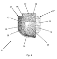
- a motor vehicle light bulbs 01 comprises at least one preferably as an LED light source 02, at least one, for example, straight or in a plane and / or curved in space three-dimensionally extending finger-shaped light guide element 03 and at least one arranged in the beam path of the light between the light source 02 and the finger-shaped light guide element 03 reflector 07th
- One or more light sources 02 may be associated with a finger-shaped light guide element 03 or a plurality of finger-shaped light guide elements 03 of one or more light sources 02, even if only one light source 02 and / or only one finger-shaped light guide element 03 is discussed later.
- the light source 01 can also have a plurality of reflectors 07, each of which reflects light to a finger-shaped light guide element 03. If the light source 01 has a plurality of finger-shaped optical waveguide elements 03, then it also requires a plurality of reflectors 07, one per finger-shaped optical waveguide element 03. If there are several light sources 02 per finger-shaped optical waveguide element 03, a reflector 07 per finger-shaped optical waveguide element 03 can, but is not necessarily, sufficient.
- the finger-shaped optical waveguide element 03 has a light input surface 04 associated with at least one light source 02 and a light exit surface 05 different from the light coupling surface 04.
- the finger-shaped light guide element 03 furthermore has one or more side walls 06 which connect the light input surface 04 and the light exit surface 05 to one another.
- the light emitted by the light source 02 in its at least one light emission direction LA enters the finger-shaped light guide element 03 exclusively via the light coupling surface 04.
- the reflector 07 is arranged in the beam path of the light between the light source 02 and the light input surface 04 of the finger-shaped light guide element 03.
- the reflector 07 redirects the light emitted by the at least one light source 02 in its at least one light emission direction LA into at least one light input direction LE to the light coupling surface 04 of the finger-shaped light conductor element 03.
- the reflector 07 consists of at least two reflector parts 08, 09.
- the Reflector sections 08, 09 are a main reflector section 08 forming a first reflector section and at least one secondary reflector section 09 forming a second reflector section, preferably angled relative to the main reflector section 08.
- the main reflector section 08 reflects and collimates the light emitted by the light source 02 in one or more light emission directions LA during the deflection in at least one Lichteinkoppelsch such that it after its entry into the finger-shaped light guide element 03 by the Lichteinkoppel configuration 04 this free of interaction, for example by Total reflection with the optically effective surfaces forming side walls 06 of the finger-shaped light guide element 03 as through the beam path LH in Fig. 1 shown passes and with refraction at the transition from the light guide material to the surrounding medium or free thereof exits through the light exit surface 05 from the finger-shaped light guide element 03 again.
- the at least one secondary reflector section 09 adjacent to the main reflector section 08 reflects and deflects the light emitted by the light source 02 in one or more light emission directions LA during the deflection in at least one light input direction LE to the light input surface 04 such that this enters the finger-shaped light guide element 03 after it has entered its light coupling surface 04 one or more times with the side walls 06 of the finger-shaped optical waveguide element 03 as through the beam path LN in Fig.
- This angle can contribute to the fulfillment of a given light distribution.
- the angle can be an angular range.
- Fig. 1 It is to be shown in Fig. 1 to hold that in the light incidence direction LE supposedly from the light source 02 to the light incidence surface 04 extending light only seems to come directly from the light source 02, but in fact has already been reflected by the reflector 07.
- Fig. 2 shows in the side view of the page, on which the supposedly wrong representation is based.
- the light exit surface 05 of the finger-shaped light guide element 03 is designed to be free of light extraction structures.
- At least one secondary reflector section 09 can be angled relative to the main reflector section 08.
- all secondary reflector sections 09 are angled relative to the main reflector section 08.
- the light input surface 04 of the finger-shaped light guide element 03 may be flat, spherical or formed as a free-form surface.
- the light coupling-in surface 04 which is designed with or without light-outcoupling elements, can be curved flat or curved in one or two dimensions or curved.
- the light incoupling surface 04 is curved in only one direction, corresponding to only one curvature about a first axis, whereas the light incoupling surface 04 is arched in a two-dimensional curved embodiment in the remaining direction, corresponding to a further curvature by a second, for example skewed to the first axis or this intersecting axis.
- the light exit surface 05 of the finger-shaped optical waveguide element 03 may be flat or curved in one or two dimensions.
- the light exit surface 05 is curved in only one direction, corresponding to only one curvature about a first axis, whereas the light exit surface 05 is arched in a two-dimensional curved embodiment in the remaining direction, corresponding to a further curvature to a second, for example skewed to the first axis or this intersecting axis.
- the side walls 06 of the finger-shaped light guide element 03 may be conical, cylindrical or rectangular.
- the side walls 06 of the finger-shaped light guide element 03 may be provided with Lichtauskoppel Modellen which direct into the finger-shaped light guide element 03 coupled light at an angle to the light exit surface 05, in which no total reflection occurs at this, so that the light the transition between the material of the finger-shaped light guide element 03 and the surrounding medium in the region of the light exit surface 05 can happen.
- the light in turn optionally exits from the light exit surface 05, with refraction when passing from the material of the finger-shaped light guide element 03 to the surrounding medium in one or more directions, for example a predetermined light distribution.
- the side walls 06 may be grained.
- At least one secondary reflector section 09 can be provided with a roll and / or cushion and / or prism structure 10 in order to deflect the light in one or more desired Lichteinkoppelschen LE.
- At least one reflector section 08, 09 can be structured with scattering elements, for example in the form of the aforementioned roll and / or cushion and / or prism structure 10. These may be provided to contribute to one or more particular Lichteinkoppelschen LE.
- the reflector 07 of the lamp 01 may comprise only two reflector sections 08, 09, a main reflector section 08 and a secondary reflector section 09 preferably angled relative to the main reflector section 08.
- the secondary reflector section 09 is arranged on one side of the main reflector section 08 or partially surrounding it.
- the reflector 07 of the luminous means 01 can consist of three reflector sections, a first, central main reflector section 08 and, on both sides of the main reflector section 08, a second secondary reflector section 09 preferably angled relative to the main reflector section 08.
- the illuminant 01 can be provided for use in a motor vehicle luminaire with a luminaire interior enclosed by a luminaire housing and a lens, in the luminaire interior of which at least one illuminant 01 fulfills at least one light function of the motor vehicle luminaire is housed.
- the light coupling takes place in the finger-shaped light guide element 03 by the finger-shaped light guide element 03 is attached to a reflector 07 denoted as indirectly.
- the reflector 07 in turn may be directly connected to a light source 02, for example an LED.
- the reflector 07 is specially adapted to the geometry of the finger-shaped light guide element 03 and converges the light accordingly, before it enters the finger-shaped light guide element 03 via the light coupling surface 04.
- the light exit surface 05 of the finger-shaped optical waveguide element 03 is little or not curved and executed free of optical elements. Nevertheless, for example, a legally prescribed light distribution is made possible.
- Light from the light exit surface 05 of the finger-shaped light guide element 03 is thereby also of angular ranges greater than 45 ° to the in Fig. 1 still visible with the optical axis coincident with the optical path LH.
- the reflector 07 covers the light incoupling surface 04 of the finger-shaped light guide element 03 in whole or in part.
- the reflector 07 consists of a centered main reflector section 08 and these surrounding angled parabolic or disorder secondary reflector sections 09.
- the main reflector section 08 and the preferably angled secondary reflector sections 09 can in turn be made with optical structures, for example with cushions, preferably with a roll and / or cushion and / or Prism structure 10 be damaged.
- Light coming from the central main reflector section 08 enters via the light coupling surface 04 in the finger-shaped light guide element 03 and passes this according to the beam path LH at least for the most part without interacting with the side walls 06.
- the light exit surface 05 At the light exit surface 05 only little or no refraction of light takes place. The latter is dependent on the curvature of the light exit surface 05.
- Light from the preferably angled secondary reflector sections 09 enters the finger-shaped optical waveguide element 03 via the light coupling surface 04 and passes this in accordance with the beam path LN with one or more interactions with the side walls 06 of the finger-shaped optical waveguide element 03.
- the angle of incidence of the light is selected such that Total reflection takes place and the light in a to optical axis steeper angle on the light exit surface 05 occurs, as is the case with the beam path LH.
- the light exit surface 05 occurs, depending on the curvature, another refraction of light instead. This light thus operates the outer or inner angular ranges of a given or desired light distribution.
- the curvature of the light exit surface 05 and optionally the scattering means arranged on the reflector 07 roll and / or cushion and / or prism structures 10 and / or scattering elements can be a uniform, seamless course of the finger-shaped light guide element 03 corresponding to the beam path LH directly passing light and the finger-shaped light guide element 03 corresponding to the beam path LN on the side walls 06 by total reflection or multiple deflected light can be achieved.
- the finger-shaped light guide element 03 thereby scatters the light into wide angular ranges of more than 45 ° with simultaneously only slightly curved light exit surface 05 and without visible optical elements on the light exit surface 05.
- the light input surface 04 of the finger-shaped light guide element 03 may be planar, spherical or designed as a free-form surface.
- the side walls 06 may be conical, cylindrical or rectangular.
- the light exit surface 05 of the finger-shaped light guide element 03 can be designed as described above.
- the side walls 06 of the finger-shaped light guide element 03 may be grained.
- the reflector 07 can also be designed as a direct reflector 07 or as a free-form surface.
- the surface of the reflector 07 may be grained or provided with scattering elements, for example with a roll and / or cushion and / or prism structure 10.
- the optical quality achievable with the invention can be further increased, because such a light source an optimal design of the entire Beam path of the light generation until it leaves the light source 01 through the light exit surface 05 of the finger-shaped light guide element 03 allows. In this way, the unwanted leakage of light at other than the intended locations of the finger-shaped optical waveguide element 03, the so-called leakage light, at least approximately completely avoided, regardless of which type LED is used as the light source 02.
- An LED comprises in addition to the already mentioned at least one LED chip and at least one contact means for electrically contacting the LED chip.
- each LED has a bonding wire per LED chip, which each electrically contacts a LED chip.
- This bonding wire forms a first contact means for the LED chip of the LED.
- the bonding wire may be connected to a first electrical connection, which may be provided for electrical contacting of the LED, for example with a first conductor track of a luminous means carrier.
- a second contact means for the LED chip of the LED forms the LED chip itself.
- For electrical contacting of the LED chip may be connected to a second electrical connection, which may be provided for electrical contacting of the LED, for example with a second conductor of a lamp carrier.
- the LED can have a primary reflector directly surrounding the LED chip.
- This primary reflector can be formed, for example, by walls of a recess surrounding the LED chip and / or by a cup in which the LED chip is arranged.
- the cup may be connected to, form or include the mentioned second port or be encompassed by it.
- LEDs are known for through-hole mounting (THT), Surface Mounted Device (SMD) LEDs and LEDs where the bare-chip LED chip (Chip On Board) is bonded directly to the illuminant carrier.
- TCT through-hole mounting
- SMD Surface Mounted Device
- LEDs where the bare-chip LED chip (Chip On Board) is bonded directly to the illuminant carrier.
- THT LEDs are the commonly known type LEDs. They are also referred to as leaded LEDs, since they are made of a transparent at least in a desired emission direction encapsulation, e.g. in the form of an encapsulation or an encapsulation, which includes a LED chip with a first electrical connection, for example in the form of an anode terminal connecting bonding wire and connected to a second electrical connection, for example in the form of a cathode terminal, LED chip. From the encapsulation protrude only the designated as little legs wires of the first electrical connection and the second electrical connection as the anode and cathode terminals of the THT-LED.
- the second electrical connection embodied, for example, as a cathode connection can in this case be provided with a cup mentioned above, in which the LED chip is arranged.
- the bonding wire leads from the example executed as an anode terminal first connection from outside the cup coming to the LED chip.
- SMD LEDs consist of a leadframe with at least one mounting surface for at least one LED chip and electrical connection surfaces.
- the leadframe is partially encapsulated by a plastic body with at least one recess freeing at least one mounting surface.
- the electrical connection surfaces of the leadframe are also kept free as the electrical connections of the SMD LED for later surface mounting.
- the at least one LED chip is arranged and electrically contacted at the bottom of the at least one recess extending to the at least one mounting surface.
- the LED chip is arranged on a first portion of the leadframe connected to at least one first electrical connection area.
- a bonding wire connects the LED chip to a second portion of the leadframe, which in turn is connected to at least one second electrical pad.
- the reaching at its base to the mounting surface recess may be designed reflector-like.
- the walls of the recess form the above-mentioned primary reflector. Here, the walls can be coated reflective.
- COB LEDs consist of one directly on a light source carrier to be arranged, unhoused LED chip and a bonding wire.
- the back side of the LED chip forms the first electrical connection of the COB LED.
- For electrical contacting of the LED chip is electrically connected on its back directly to a first conductor of a light source carrier, for example by soldering or welding.
- the bonding wire forming the second electrical connection of the COB LED is also electrically connected to a second conductor track of the illuminant carrier, for example by soldering or welding.
- One or more of the aforementioned light source carriers may be part of a light source 01.
- the invention is particularly applicable in the field of the production of light sources, as may be provided, for example, for motor vehicle lights, as well as in the field of production of motor vehicle lights industrially applicable.
Landscapes
- Engineering & Computer Science (AREA)
- General Engineering & Computer Science (AREA)
- Physics & Mathematics (AREA)
- Microelectronics & Electronic Packaging (AREA)
- Optics & Photonics (AREA)
- Planar Illumination Modules (AREA)
- Arrangements Of Lighting Devices For Vehicle Interiors, Mounting And Supporting Thereof, Circuits Therefore (AREA)
Priority Applications (2)
| Application Number | Priority Date | Filing Date | Title |
|---|---|---|---|
| EP12197421.6A EP2743565B1 (fr) | 2012-12-17 | 2012-12-17 | Dispositif d'éclairage avec un élément conducteur de lumière en forme de doigt et un réflecteur comportant deux facettes |
| SI201230688A SI2743565T1 (sl) | 2012-12-17 | 2012-12-17 | Svetilna naprava z vodilnim elementom svetlobe v obliki prsta in pripadajoč reflektor z dvema reflektorskima deloma |
Applications Claiming Priority (1)
| Application Number | Priority Date | Filing Date | Title |
|---|---|---|---|
| EP12197421.6A EP2743565B1 (fr) | 2012-12-17 | 2012-12-17 | Dispositif d'éclairage avec un élément conducteur de lumière en forme de doigt et un réflecteur comportant deux facettes |
Publications (2)
| Publication Number | Publication Date |
|---|---|
| EP2743565A1 true EP2743565A1 (fr) | 2014-06-18 |
| EP2743565B1 EP2743565B1 (fr) | 2016-06-01 |
Family
ID=47709761
Family Applications (1)
| Application Number | Title | Priority Date | Filing Date |
|---|---|---|---|
| EP12197421.6A Active EP2743565B1 (fr) | 2012-12-17 | 2012-12-17 | Dispositif d'éclairage avec un élément conducteur de lumière en forme de doigt et un réflecteur comportant deux facettes |
Country Status (2)
| Country | Link |
|---|---|
| EP (1) | EP2743565B1 (fr) |
| SI (1) | SI2743565T1 (fr) |
Cited By (4)
| Publication number | Priority date | Publication date | Assignee | Title |
|---|---|---|---|---|
| WO2017015684A1 (fr) * | 2015-07-28 | 2017-02-02 | Zkw Group Gmbh | Dispositif d'éclairage destiné à un phare de véhicule à moteur |
| CN108302471A (zh) * | 2016-09-14 | 2018-07-20 | 英属维尔京群岛商博伦思国际股份有限公司 | 光学模块及光学元件 |
| WO2021205084A1 (fr) * | 2020-04-09 | 2021-10-14 | Psa Automobiles Sa | Dispositif optique pour véhicule automobile présentant un aspect de guide plat de lumière |
| DE102022106420A1 (de) | 2022-03-18 | 2023-09-21 | Marelli Automotive Lighting Reutlingen (Germany) GmbH | Signalleuchte für eine Kraftfahrzeugbeleuchtungseinrichtung |
Citations (8)
| Publication number | Priority date | Publication date | Assignee | Title |
|---|---|---|---|---|
| JPH02164612A (ja) | 1988-12-16 | 1990-06-25 | Nissan Motor Co Ltd | 自動車用サンバイザー |
| JPH06203606A (ja) | 1992-09-10 | 1994-07-22 | General Electric Co <Ge> | 光ガイドを用いた照明装置 |
| EP1152188A2 (fr) * | 2000-04-05 | 2001-11-07 | Philips Corporate Intellectual Property GmbH | Dispositif d'éclairage et méthode pour son exploitation |
| US20040012976A1 (en) * | 2002-07-15 | 2004-01-22 | Koito Manufacturing Co., Ltd. | Vehicular lamp |
| EP1801492A1 (fr) | 2005-12-20 | 2007-06-27 | Valeo Vision | Dispositif d'éclairage ou de signalisation à guide optique pour véhicule automobile |
| EP1881258A1 (fr) | 2006-07-20 | 2008-01-23 | Schefenacker Vision Systems Germany GmbH | Unité d'éclairage dotée d'une diode à corps de changement de direction de la lumière intégré |
| EP2372235A2 (fr) * | 2010-03-27 | 2011-10-05 | Automotive Lighting Reutlingen GmbH | Lampe de véhicule dotée d'une optique de montage conductrice de lumière |
| DE102010041096A1 (de) * | 2010-09-21 | 2012-03-22 | Osram Ag | Leuchtvorrichtung |
-
2012
- 2012-12-17 SI SI201230688A patent/SI2743565T1/sl unknown
- 2012-12-17 EP EP12197421.6A patent/EP2743565B1/fr active Active
Patent Citations (9)
| Publication number | Priority date | Publication date | Assignee | Title |
|---|---|---|---|---|
| JPH02164612A (ja) | 1988-12-16 | 1990-06-25 | Nissan Motor Co Ltd | 自動車用サンバイザー |
| JPH06203606A (ja) | 1992-09-10 | 1994-07-22 | General Electric Co <Ge> | 光ガイドを用いた照明装置 |
| EP1152188A2 (fr) * | 2000-04-05 | 2001-11-07 | Philips Corporate Intellectual Property GmbH | Dispositif d'éclairage et méthode pour son exploitation |
| US20040012976A1 (en) * | 2002-07-15 | 2004-01-22 | Koito Manufacturing Co., Ltd. | Vehicular lamp |
| EP1801492A1 (fr) | 2005-12-20 | 2007-06-27 | Valeo Vision | Dispositif d'éclairage ou de signalisation à guide optique pour véhicule automobile |
| EP1881258A1 (fr) | 2006-07-20 | 2008-01-23 | Schefenacker Vision Systems Germany GmbH | Unité d'éclairage dotée d'une diode à corps de changement de direction de la lumière intégré |
| DE102006034070A1 (de) | 2006-07-20 | 2008-01-31 | Schefenacker Vision Systems Germany Gmbh | Leuchteinheit mit einer Leuchtdiode mit integriertem Lichtumlenkkörper |
| EP2372235A2 (fr) * | 2010-03-27 | 2011-10-05 | Automotive Lighting Reutlingen GmbH | Lampe de véhicule dotée d'une optique de montage conductrice de lumière |
| DE102010041096A1 (de) * | 2010-09-21 | 2012-03-22 | Osram Ag | Leuchtvorrichtung |
Cited By (7)
| Publication number | Priority date | Publication date | Assignee | Title |
|---|---|---|---|---|
| WO2017015684A1 (fr) * | 2015-07-28 | 2017-02-02 | Zkw Group Gmbh | Dispositif d'éclairage destiné à un phare de véhicule à moteur |
| US10018317B2 (en) | 2015-07-28 | 2018-07-10 | Zkw Group Gmbh | Lighting device for a motor vehicle headlamp |
| CN108302471A (zh) * | 2016-09-14 | 2018-07-20 | 英属维尔京群岛商博伦思国际股份有限公司 | 光学模块及光学元件 |
| WO2021205084A1 (fr) * | 2020-04-09 | 2021-10-14 | Psa Automobiles Sa | Dispositif optique pour véhicule automobile présentant un aspect de guide plat de lumière |
| FR3109203A1 (fr) * | 2020-04-09 | 2021-10-15 | Psa Automobiles Sa | Dispositif optique pour phare présentant un aspect de guide plat de lumière. |
| DE102022106420A1 (de) | 2022-03-18 | 2023-09-21 | Marelli Automotive Lighting Reutlingen (Germany) GmbH | Signalleuchte für eine Kraftfahrzeugbeleuchtungseinrichtung |
| US11906127B2 (en) | 2022-03-18 | 2024-02-20 | Marelli Automotive Lighting Reutlingen (Germany) GmbH | Signal lights for a motor vehicle lighting system |
Also Published As
| Publication number | Publication date |
|---|---|
| EP2743565B1 (fr) | 2016-06-01 |
| SI2743565T1 (sl) | 2016-10-28 |
Similar Documents
| Publication | Publication Date | Title |
|---|---|---|
| EP2587120B1 (fr) | Conduit de lumière et vèhicule automobile muni d'un tel conduit de lumière | |
| EP2889529B1 (fr) | Éclairage de véhicule automobile doté d'une apparence extensive ou linéaire | |
| EP1886871B1 (fr) | Feu de signalisation pour véhicules | |
| EP2607774B1 (fr) | Dispositif d'éclairage d'un véhicule automobile avec une surface lumineuse longue et plane | |
| DE102013212353B4 (de) | Kraftfahrzeugbeleuchtungseinrichtung mit einer eine Einkoppeloptik und eine Transport- und Umformoptik aufweisenden Lichtleiteranordnung | |
| DE102010018119B4 (de) | Optikelement für eine Beleuchtungseinrichtung eines Fahrzeugs | |
| EP1327558A2 (fr) | Lampe pour véhicule | |
| EP2428724A1 (fr) | Couplage de lumière optimal pour dispositifs rétroviseurs | |
| EP2527722A2 (fr) | Dispositif d'éclairage pour un véhicule automobile | |
| EP2784379A1 (fr) | Conducteur lumineux doté d'une surface de sortie de lumière en forme de bande | |
| EP3015761B1 (fr) | Dispositif d'éclairage avec élément optique | |
| DE102006062272A1 (de) | Fahrzeugleuchte | |
| EP2384934A1 (fr) | Lampe de véhicule automobile avec plusieurs fonctions d'éclairage | |
| DE102012202508A1 (de) | Lichtleitervorrichtung für eine Kraftfahrzeugleuchte | |
| EP2500753B1 (fr) | Conducteur lumineux doté d'éléments de déclenchement déclenchés à lumière directe | |
| EP2618045A1 (fr) | Dispositif dýéclairage pour un véhicule automobile | |
| EP1826475A1 (fr) | Système d'éclairage plat avec LED et guide d'onde | |
| EP2743565B1 (fr) | Dispositif d'éclairage avec un élément conducteur de lumière en forme de doigt et un réflecteur comportant deux facettes | |
| DE102008061716A1 (de) | Fahrzeugleuchte und Leuchtensystem | |
| DE10311317A1 (de) | Leuchteinrichtung für Fahrzeuge | |
| DE112018004747T5 (de) | Leuchtvorrichtung eines Kraftfahrzeugs | |
| EP2490052B1 (fr) | Dispositif d'éclairage d'un véhicule automobile | |
| EP1464888B1 (fr) | Feu pour véhicule | |
| DE102011051541B4 (de) | Beleuchtungsvorrichtung für Fahrzeuge | |
| DE102017105838A1 (de) | Beleuchtungseinrichtung eines Kraftfahrzeugs mit einer Lichtleiteranordnung |
Legal Events
| Date | Code | Title | Description |
|---|---|---|---|
| PUAI | Public reference made under article 153(3) epc to a published international application that has entered the european phase |
Free format text: ORIGINAL CODE: 0009012 |
|
| 17P | Request for examination filed |
Effective date: 20130828 |
|
| AK | Designated contracting states |
Kind code of ref document: A1 Designated state(s): AL AT BE BG CH CY CZ DE DK EE ES FI FR GB GR HR HU IE IS IT LI LT LU LV MC MK MT NL NO PL PT RO RS SE SI SK SM TR |
|
| AX | Request for extension of the european patent |
Extension state: BA ME |
|
| RAP1 | Party data changed (applicant data changed or rights of an application transferred) |
Owner name: ODELO GMBH |
|
| GRAP | Despatch of communication of intention to grant a patent |
Free format text: ORIGINAL CODE: EPIDOSNIGR1 |
|
| INTG | Intention to grant announced |
Effective date: 20160118 |
|
| GRAS | Grant fee paid |
Free format text: ORIGINAL CODE: EPIDOSNIGR3 |
|
| GRAA | (expected) grant |
Free format text: ORIGINAL CODE: 0009210 |
|
| AK | Designated contracting states |
Kind code of ref document: B1 Designated state(s): AL AT BE BG CH CY CZ DE DK EE ES FI FR GB GR HR HU IE IS IT LI LT LU LV MC MK MT NL NO PL PT RO RS SE SI SK SM TR |
|
| REG | Reference to a national code |
Ref country code: GB Ref legal event code: FG4D Free format text: NOT ENGLISH |
|
| REG | Reference to a national code |
Ref country code: CH Ref legal event code: EP Ref country code: AT Ref legal event code: REF Ref document number: 804108 Country of ref document: AT Kind code of ref document: T Effective date: 20160615 |
|
| REG | Reference to a national code |
Ref country code: IE Ref legal event code: FG4D Free format text: LANGUAGE OF EP DOCUMENT: GERMAN |
|
| REG | Reference to a national code |
Ref country code: DE Ref legal event code: R096 Ref document number: 502012007290 Country of ref document: DE |
|
| REG | Reference to a national code |
Ref country code: LT Ref legal event code: MG4D |
|
| REG | Reference to a national code |
Ref country code: NL Ref legal event code: MP Effective date: 20160601 |
|
| PG25 | Lapsed in a contracting state [announced via postgrant information from national office to epo] |
Ref country code: LT Free format text: LAPSE BECAUSE OF FAILURE TO SUBMIT A TRANSLATION OF THE DESCRIPTION OR TO PAY THE FEE WITHIN THE PRESCRIBED TIME-LIMIT Effective date: 20160601 Ref country code: NO Free format text: LAPSE BECAUSE OF FAILURE TO SUBMIT A TRANSLATION OF THE DESCRIPTION OR TO PAY THE FEE WITHIN THE PRESCRIBED TIME-LIMIT Effective date: 20160901 Ref country code: FI Free format text: LAPSE BECAUSE OF FAILURE TO SUBMIT A TRANSLATION OF THE DESCRIPTION OR TO PAY THE FEE WITHIN THE PRESCRIBED TIME-LIMIT Effective date: 20160601 |
|
| PG25 | Lapsed in a contracting state [announced via postgrant information from national office to epo] |
Ref country code: HR Free format text: LAPSE BECAUSE OF FAILURE TO SUBMIT A TRANSLATION OF THE DESCRIPTION OR TO PAY THE FEE WITHIN THE PRESCRIBED TIME-LIMIT Effective date: 20160601 Ref country code: LV Free format text: LAPSE BECAUSE OF FAILURE TO SUBMIT A TRANSLATION OF THE DESCRIPTION OR TO PAY THE FEE WITHIN THE PRESCRIBED TIME-LIMIT Effective date: 20160601 Ref country code: NL Free format text: LAPSE BECAUSE OF FAILURE TO SUBMIT A TRANSLATION OF THE DESCRIPTION OR TO PAY THE FEE WITHIN THE PRESCRIBED TIME-LIMIT Effective date: 20160601 Ref country code: GR Free format text: LAPSE BECAUSE OF FAILURE TO SUBMIT A TRANSLATION OF THE DESCRIPTION OR TO PAY THE FEE WITHIN THE PRESCRIBED TIME-LIMIT Effective date: 20160902 Ref country code: RS Free format text: LAPSE BECAUSE OF FAILURE TO SUBMIT A TRANSLATION OF THE DESCRIPTION OR TO PAY THE FEE WITHIN THE PRESCRIBED TIME-LIMIT Effective date: 20160601 Ref country code: SE Free format text: LAPSE BECAUSE OF FAILURE TO SUBMIT A TRANSLATION OF THE DESCRIPTION OR TO PAY THE FEE WITHIN THE PRESCRIBED TIME-LIMIT Effective date: 20160601 Ref country code: ES Free format text: LAPSE BECAUSE OF FAILURE TO SUBMIT A TRANSLATION OF THE DESCRIPTION OR TO PAY THE FEE WITHIN THE PRESCRIBED TIME-LIMIT Effective date: 20160601 |
|
| REG | Reference to a national code |
Ref country code: FR Ref legal event code: PLFP Year of fee payment: 5 |
|
| PG25 | Lapsed in a contracting state [announced via postgrant information from national office to epo] |
Ref country code: RO Free format text: LAPSE BECAUSE OF FAILURE TO SUBMIT A TRANSLATION OF THE DESCRIPTION OR TO PAY THE FEE WITHIN THE PRESCRIBED TIME-LIMIT Effective date: 20160601 Ref country code: SK Free format text: LAPSE BECAUSE OF FAILURE TO SUBMIT A TRANSLATION OF THE DESCRIPTION OR TO PAY THE FEE WITHIN THE PRESCRIBED TIME-LIMIT Effective date: 20160601 Ref country code: EE Free format text: LAPSE BECAUSE OF FAILURE TO SUBMIT A TRANSLATION OF THE DESCRIPTION OR TO PAY THE FEE WITHIN THE PRESCRIBED TIME-LIMIT Effective date: 20160601 Ref country code: IS Free format text: LAPSE BECAUSE OF FAILURE TO SUBMIT A TRANSLATION OF THE DESCRIPTION OR TO PAY THE FEE WITHIN THE PRESCRIBED TIME-LIMIT Effective date: 20161001 Ref country code: CZ Free format text: LAPSE BECAUSE OF FAILURE TO SUBMIT A TRANSLATION OF THE DESCRIPTION OR TO PAY THE FEE WITHIN THE PRESCRIBED TIME-LIMIT Effective date: 20160601 Ref country code: IT Free format text: LAPSE BECAUSE OF FAILURE TO SUBMIT A TRANSLATION OF THE DESCRIPTION OR TO PAY THE FEE WITHIN THE PRESCRIBED TIME-LIMIT Effective date: 20160601 |
|
| PG25 | Lapsed in a contracting state [announced via postgrant information from national office to epo] |
Ref country code: PL Free format text: LAPSE BECAUSE OF FAILURE TO SUBMIT A TRANSLATION OF THE DESCRIPTION OR TO PAY THE FEE WITHIN THE PRESCRIBED TIME-LIMIT Effective date: 20160601 Ref country code: SM Free format text: LAPSE BECAUSE OF FAILURE TO SUBMIT A TRANSLATION OF THE DESCRIPTION OR TO PAY THE FEE WITHIN THE PRESCRIBED TIME-LIMIT Effective date: 20160601 Ref country code: PT Free format text: LAPSE BECAUSE OF FAILURE TO SUBMIT A TRANSLATION OF THE DESCRIPTION OR TO PAY THE FEE WITHIN THE PRESCRIBED TIME-LIMIT Effective date: 20161003 |
|
| REG | Reference to a national code |
Ref country code: DE Ref legal event code: R097 Ref document number: 502012007290 Country of ref document: DE |
|
| PLBE | No opposition filed within time limit |
Free format text: ORIGINAL CODE: 0009261 |
|
| STAA | Information on the status of an ep patent application or granted ep patent |
Free format text: STATUS: NO OPPOSITION FILED WITHIN TIME LIMIT |
|
| 26N | No opposition filed |
Effective date: 20170302 |
|
| PG25 | Lapsed in a contracting state [announced via postgrant information from national office to epo] |
Ref country code: DK Free format text: LAPSE BECAUSE OF FAILURE TO SUBMIT A TRANSLATION OF THE DESCRIPTION OR TO PAY THE FEE WITHIN THE PRESCRIBED TIME-LIMIT Effective date: 20160601 Ref country code: BE Free format text: LAPSE BECAUSE OF NON-PAYMENT OF DUE FEES Effective date: 20161231 |
|
| REG | Reference to a national code |
Ref country code: CH Ref legal event code: PL |
|
| GBPC | Gb: european patent ceased through non-payment of renewal fee |
Effective date: 20161217 |
|
| PG25 | Lapsed in a contracting state [announced via postgrant information from national office to epo] |
Ref country code: MC Free format text: LAPSE BECAUSE OF FAILURE TO SUBMIT A TRANSLATION OF THE DESCRIPTION OR TO PAY THE FEE WITHIN THE PRESCRIBED TIME-LIMIT Effective date: 20160601 |
|
| REG | Reference to a national code |
Ref country code: IE Ref legal event code: MM4A |
|
| PG25 | Lapsed in a contracting state [announced via postgrant information from national office to epo] |
Ref country code: CH Free format text: LAPSE BECAUSE OF NON-PAYMENT OF DUE FEES Effective date: 20161231 Ref country code: LI Free format text: LAPSE BECAUSE OF NON-PAYMENT OF DUE FEES Effective date: 20161231 Ref country code: LU Free format text: LAPSE BECAUSE OF NON-PAYMENT OF DUE FEES Effective date: 20161217 |
|
| REG | Reference to a national code |
Ref country code: DE Ref legal event code: R079 Ref document number: 502012007290 Country of ref document: DE Free format text: PREVIOUS MAIN CLASS: F21S0008100000 Ipc: F21S0043000000 |
|
| PG25 | Lapsed in a contracting state [announced via postgrant information from national office to epo] |
Ref country code: IE Free format text: LAPSE BECAUSE OF NON-PAYMENT OF DUE FEES Effective date: 20161217 Ref country code: GB Free format text: LAPSE BECAUSE OF NON-PAYMENT OF DUE FEES Effective date: 20161217 |
|
| REG | Reference to a national code |
Ref country code: FR Ref legal event code: PLFP Year of fee payment: 6 |
|
| REG | Reference to a national code |
Ref country code: BE Ref legal event code: MM Effective date: 20161231 |
|
| PG25 | Lapsed in a contracting state [announced via postgrant information from national office to epo] |
Ref country code: HU Free format text: LAPSE BECAUSE OF FAILURE TO SUBMIT A TRANSLATION OF THE DESCRIPTION OR TO PAY THE FEE WITHIN THE PRESCRIBED TIME-LIMIT; INVALID AB INITIO Effective date: 20121217 |
|
| PG25 | Lapsed in a contracting state [announced via postgrant information from national office to epo] |
Ref country code: MK Free format text: LAPSE BECAUSE OF FAILURE TO SUBMIT A TRANSLATION OF THE DESCRIPTION OR TO PAY THE FEE WITHIN THE PRESCRIBED TIME-LIMIT Effective date: 20160601 Ref country code: CY Free format text: LAPSE BECAUSE OF FAILURE TO SUBMIT A TRANSLATION OF THE DESCRIPTION OR TO PAY THE FEE WITHIN THE PRESCRIBED TIME-LIMIT Effective date: 20160601 |
|
| PG25 | Lapsed in a contracting state [announced via postgrant information from national office to epo] |
Ref country code: BG Free format text: LAPSE BECAUSE OF FAILURE TO SUBMIT A TRANSLATION OF THE DESCRIPTION OR TO PAY THE FEE WITHIN THE PRESCRIBED TIME-LIMIT Effective date: 20160601 |
|
| PG25 | Lapsed in a contracting state [announced via postgrant information from national office to epo] |
Ref country code: MT Free format text: LAPSE BECAUSE OF FAILURE TO SUBMIT A TRANSLATION OF THE DESCRIPTION OR TO PAY THE FEE WITHIN THE PRESCRIBED TIME-LIMIT Effective date: 20160601 |
|
| PG25 | Lapsed in a contracting state [announced via postgrant information from national office to epo] |
Ref country code: AL Free format text: LAPSE BECAUSE OF FAILURE TO SUBMIT A TRANSLATION OF THE DESCRIPTION OR TO PAY THE FEE WITHIN THE PRESCRIBED TIME-LIMIT Effective date: 20160601 Ref country code: TR Free format text: LAPSE BECAUSE OF FAILURE TO SUBMIT A TRANSLATION OF THE DESCRIPTION OR TO PAY THE FEE WITHIN THE PRESCRIBED TIME-LIMIT Effective date: 20160601 |
|
| REG | Reference to a national code |
Ref country code: AT Ref legal event code: MM01 Ref document number: 804108 Country of ref document: AT Kind code of ref document: T Effective date: 20171217 |
|
| PG25 | Lapsed in a contracting state [announced via postgrant information from national office to epo] |
Ref country code: AT Free format text: LAPSE BECAUSE OF NON-PAYMENT OF DUE FEES Effective date: 20171217 |
|
| PGFP | Annual fee paid to national office [announced via postgrant information from national office to epo] |
Ref country code: SI Payment date: 20231207 Year of fee payment: 12 Ref country code: FR Payment date: 20231221 Year of fee payment: 12 Ref country code: DE Payment date: 20231214 Year of fee payment: 12 |