EP2742916B1 - Medizinisches Implantat, Behandlungssystem mit einem derartigen Implantat und Verfahren zum Herstellen eines Implantats - Google Patents
Medizinisches Implantat, Behandlungssystem mit einem derartigen Implantat und Verfahren zum Herstellen eines Implantats Download PDFInfo
- Publication number
- EP2742916B1 EP2742916B1 EP13197735.7A EP13197735A EP2742916B1 EP 2742916 B1 EP2742916 B1 EP 2742916B1 EP 13197735 A EP13197735 A EP 13197735A EP 2742916 B1 EP2742916 B1 EP 2742916B1
- Authority
- EP
- European Patent Office
- Prior art keywords
- peripheral wall
- webs
- implant
- cross
- radially
- Prior art date
- Legal status (The legal status is an assumption and is not a legal conclusion. Google has not performed a legal analysis and makes no representation as to the accuracy of the status listed.)
- Active
Links
Images




Classifications
-
- A—HUMAN NECESSITIES
- A61—MEDICAL OR VETERINARY SCIENCE; HYGIENE
- A61F—FILTERS IMPLANTABLE INTO BLOOD VESSELS; PROSTHESES; DEVICES PROVIDING PATENCY TO, OR PREVENTING COLLAPSING OF, TUBULAR STRUCTURES OF THE BODY, e.g. STENTS; ORTHOPAEDIC, NURSING OR CONTRACEPTIVE DEVICES; FOMENTATION; TREATMENT OR PROTECTION OF EYES OR EARS; BANDAGES, DRESSINGS OR ABSORBENT PADS; FIRST-AID KITS
- A61F2/00—Filters implantable into blood vessels; Prostheses, i.e. artificial substitutes or replacements for parts of the body; Appliances for connecting them with the body; Devices providing patency to, or preventing collapsing of, tubular structures of the body, e.g. stents
- A61F2/82—Devices providing patency to, or preventing collapsing of, tubular structures of the body, e.g. stents
- A61F2/86—Stents in a form characterised by the wire-like elements; Stents in the form characterised by a net-like or mesh-like structure
- A61F2/90—Stents in a form characterised by the wire-like elements; Stents in the form characterised by a net-like or mesh-like structure characterised by a net-like or mesh-like structure
- A61F2/91—Stents in a form characterised by the wire-like elements; Stents in the form characterised by a net-like or mesh-like structure characterised by a net-like or mesh-like structure made from perforated sheets or tubes, e.g. perforated by laser cuts or etched holes
-
- A—HUMAN NECESSITIES
- A61—MEDICAL OR VETERINARY SCIENCE; HYGIENE
- A61F—FILTERS IMPLANTABLE INTO BLOOD VESSELS; PROSTHESES; DEVICES PROVIDING PATENCY TO, OR PREVENTING COLLAPSING OF, TUBULAR STRUCTURES OF THE BODY, e.g. STENTS; ORTHOPAEDIC, NURSING OR CONTRACEPTIVE DEVICES; FOMENTATION; TREATMENT OR PROTECTION OF EYES OR EARS; BANDAGES, DRESSINGS OR ABSORBENT PADS; FIRST-AID KITS
- A61F2/00—Filters implantable into blood vessels; Prostheses, i.e. artificial substitutes or replacements for parts of the body; Appliances for connecting them with the body; Devices providing patency to, or preventing collapsing of, tubular structures of the body, e.g. stents
- A61F2/01—Filters implantable into blood vessels
- A61F2/0105—Open ended, i.e. legs gathered only at one side
-
- A—HUMAN NECESSITIES
- A61—MEDICAL OR VETERINARY SCIENCE; HYGIENE
- A61F—FILTERS IMPLANTABLE INTO BLOOD VESSELS; PROSTHESES; DEVICES PROVIDING PATENCY TO, OR PREVENTING COLLAPSING OF, TUBULAR STRUCTURES OF THE BODY, e.g. STENTS; ORTHOPAEDIC, NURSING OR CONTRACEPTIVE DEVICES; FOMENTATION; TREATMENT OR PROTECTION OF EYES OR EARS; BANDAGES, DRESSINGS OR ABSORBENT PADS; FIRST-AID KITS
- A61F2/00—Filters implantable into blood vessels; Prostheses, i.e. artificial substitutes or replacements for parts of the body; Appliances for connecting them with the body; Devices providing patency to, or preventing collapsing of, tubular structures of the body, e.g. stents
- A61F2/01—Filters implantable into blood vessels
-
- A—HUMAN NECESSITIES
- A61—MEDICAL OR VETERINARY SCIENCE; HYGIENE
- A61F—FILTERS IMPLANTABLE INTO BLOOD VESSELS; PROSTHESES; DEVICES PROVIDING PATENCY TO, OR PREVENTING COLLAPSING OF, TUBULAR STRUCTURES OF THE BODY, e.g. STENTS; ORTHOPAEDIC, NURSING OR CONTRACEPTIVE DEVICES; FOMENTATION; TREATMENT OR PROTECTION OF EYES OR EARS; BANDAGES, DRESSINGS OR ABSORBENT PADS; FIRST-AID KITS
- A61F2/00—Filters implantable into blood vessels; Prostheses, i.e. artificial substitutes or replacements for parts of the body; Appliances for connecting them with the body; Devices providing patency to, or preventing collapsing of, tubular structures of the body, e.g. stents
- A61F2/01—Filters implantable into blood vessels
- A61F2002/018—Filters implantable into blood vessels made from tubes or sheets of material, e.g. by etching or laser-cutting
-
- A—HUMAN NECESSITIES
- A61—MEDICAL OR VETERINARY SCIENCE; HYGIENE
- A61F—FILTERS IMPLANTABLE INTO BLOOD VESSELS; PROSTHESES; DEVICES PROVIDING PATENCY TO, OR PREVENTING COLLAPSING OF, TUBULAR STRUCTURES OF THE BODY, e.g. STENTS; ORTHOPAEDIC, NURSING OR CONTRACEPTIVE DEVICES; FOMENTATION; TREATMENT OR PROTECTION OF EYES OR EARS; BANDAGES, DRESSINGS OR ABSORBENT PADS; FIRST-AID KITS
- A61F2230/00—Geometry of prostheses classified in groups A61F2/00 - A61F2/26 or A61F2/82 or A61F9/00 or A61F11/00 or subgroups thereof
- A61F2230/0002—Two-dimensional shapes, e.g. cross-sections
- A61F2230/0017—Angular shapes
- A61F2230/0023—Angular shapes triangular
-
- A—HUMAN NECESSITIES
- A61—MEDICAL OR VETERINARY SCIENCE; HYGIENE
- A61F—FILTERS IMPLANTABLE INTO BLOOD VESSELS; PROSTHESES; DEVICES PROVIDING PATENCY TO, OR PREVENTING COLLAPSING OF, TUBULAR STRUCTURES OF THE BODY, e.g. STENTS; ORTHOPAEDIC, NURSING OR CONTRACEPTIVE DEVICES; FOMENTATION; TREATMENT OR PROTECTION OF EYES OR EARS; BANDAGES, DRESSINGS OR ABSORBENT PADS; FIRST-AID KITS
- A61F2230/00—Geometry of prostheses classified in groups A61F2/00 - A61F2/26 or A61F2/82 or A61F9/00 or A61F11/00 or subgroups thereof
- A61F2230/0002—Two-dimensional shapes, e.g. cross-sections
- A61F2230/0017—Angular shapes
- A61F2230/0026—Angular shapes trapezoidal
-
- A—HUMAN NECESSITIES
- A61—MEDICAL OR VETERINARY SCIENCE; HYGIENE
- A61F—FILTERS IMPLANTABLE INTO BLOOD VESSELS; PROSTHESES; DEVICES PROVIDING PATENCY TO, OR PREVENTING COLLAPSING OF, TUBULAR STRUCTURES OF THE BODY, e.g. STENTS; ORTHOPAEDIC, NURSING OR CONTRACEPTIVE DEVICES; FOMENTATION; TREATMENT OR PROTECTION OF EYES OR EARS; BANDAGES, DRESSINGS OR ABSORBENT PADS; FIRST-AID KITS
- A61F2240/00—Manufacturing or designing of prostheses classified in groups A61F2/00 - A61F2/26 or A61F2/82 or A61F9/00 or A61F11/00 or subgroups thereof
- A61F2240/001—Designing or manufacturing processes
-
- A—HUMAN NECESSITIES
- A61—MEDICAL OR VETERINARY SCIENCE; HYGIENE
- A61F—FILTERS IMPLANTABLE INTO BLOOD VESSELS; PROSTHESES; DEVICES PROVIDING PATENCY TO, OR PREVENTING COLLAPSING OF, TUBULAR STRUCTURES OF THE BODY, e.g. STENTS; ORTHOPAEDIC, NURSING OR CONTRACEPTIVE DEVICES; FOMENTATION; TREATMENT OR PROTECTION OF EYES OR EARS; BANDAGES, DRESSINGS OR ABSORBENT PADS; FIRST-AID KITS
- A61F2250/00—Special features of prostheses classified in groups A61F2/00 - A61F2/26 or A61F2/82 or A61F9/00 or A61F11/00 or subgroups thereof
- A61F2250/0014—Special features of prostheses classified in groups A61F2/00 - A61F2/26 or A61F2/82 or A61F9/00 or A61F11/00 or subgroups thereof having different values of a given property or geometrical feature, e.g. mechanical property or material property, at different locations within the same prosthesis
- A61F2250/0032—Special features of prostheses classified in groups A61F2/00 - A61F2/26 or A61F2/82 or A61F9/00 or A61F11/00 or subgroups thereof having different values of a given property or geometrical feature, e.g. mechanical property or material property, at different locations within the same prosthesis differing in radiographic density
-
- A—HUMAN NECESSITIES
- A61—MEDICAL OR VETERINARY SCIENCE; HYGIENE
- A61F—FILTERS IMPLANTABLE INTO BLOOD VESSELS; PROSTHESES; DEVICES PROVIDING PATENCY TO, OR PREVENTING COLLAPSING OF, TUBULAR STRUCTURES OF THE BODY, e.g. STENTS; ORTHOPAEDIC, NURSING OR CONTRACEPTIVE DEVICES; FOMENTATION; TREATMENT OR PROTECTION OF EYES OR EARS; BANDAGES, DRESSINGS OR ABSORBENT PADS; FIRST-AID KITS
- A61F2250/00—Special features of prostheses classified in groups A61F2/00 - A61F2/26 or A61F2/82 or A61F9/00 or A61F11/00 or subgroups thereof
- A61F2250/0014—Special features of prostheses classified in groups A61F2/00 - A61F2/26 or A61F2/82 or A61F9/00 or A61F11/00 or subgroups thereof having different values of a given property or geometrical feature, e.g. mechanical property or material property, at different locations within the same prosthesis
- A61F2250/0043—Special features of prostheses classified in groups A61F2/00 - A61F2/26 or A61F2/82 or A61F9/00 or A61F11/00 or subgroups thereof having different values of a given property or geometrical feature, e.g. mechanical property or material property, at different locations within the same prosthesis differing in electric properties, e.g. in electrical conductivity, in galvanic properties
Definitions
- the invention relates to a medical implant, a treatment system with such an implant and a method for producing a medical implant.
- Medical implants with a radially compressible and radially expandable peripheral wall are usually formed from a mesh of wires or a cell structure, wherein the cells are delimited by webs.
- the webs are integrally connected to each other and thus form the peripheral wall whose cross-sectional diameter is variable.
- the production of peripheral walls formed by webs is carried out by a cutting process, wherein a tube is provided, from the wall of which the cells of the peripheral wall to be produced are cut out. By cutting out the cells, the webs are formed, which have a rectangular or trapezoidal cross-sectional contour.
- the trapezoidal cross-sectional contour of the webs limits the compressibility.
- the smallest possible compressed cross-sectional diameter substantially corresponds to the cross-sectional diameter of the tube which forms the template for the stent.
- the tube must have a minimum diameter in order to provide the desired wall thickness for the stent on the one hand and on the other hand to leave open a passageway which penetrates the tube longitudinally.
- the device comprises an expandable catch element formed by longitudinal cuts in a wire, the wire, in use, leading out of the body of a patient to permit extraction of the catch element.
- a disadvantage of the known device that the movement and arrangement of Fangelements within the body of the patient because of limited radiopaque properties is difficult to observe and control.
- the device is not suitable for remaining within the body and therefore can not be used as an implant.
- the invention has for its object to provide a medical implant that can be easily manufactured and has the smallest possible compressed cross-sectional diameter. It is another object of the invention to provide a treatment system with such an implant and a method for producing a medical implant.
- this object is achieved with regard to the medical implant by the subject-matter of claim 1, with regard to the treatment system by the subject-matter of patent claim 5 and with regard to the method by the subject-matter of patent claim 6.
- the invention is based on the idea to provide a medical implant with a radially compressible and radially expandable circular cylindrical peripheral wall, which is integrally formed from webs.
- the webs have (essentially) a cake-piece-like cross-sectional shape.
- a medical device such as a thrombectomy device, a flow diverter, or a blood filter.
- a medical device such as a thrombectomy device, a flow diverter, or a blood filter.
- Such devices usually have an expandable portion which behaves analogously to the implant described in detail herein.
- the expandable portion is fixed, in particular monolithic, connected to a transport element or forms a distal end portion of the transport element.
- the inventive medical implant or its circular cylindrical peripheral wall can be compressed to a particularly small cross-sectional diameter. This facilitates the delivery of the medical implant into small hollow organs of the body, for example into small blood vessels.
- the cross-sectional shape of the medical implant also offers an extremely low flow resistance, so that a fluid flow in the hollow organs of the body is hardly affected.
- the production of the medical implant according to the invention is simplified because no tube but a solid material is used as the starting material.
- material inaccuracies, such as irregular surface texture, that may occur with tubular starting materials on the inner peripheral surface can be avoided.
- the medical implant according to the invention therefore has a particularly high production accuracy.
- the webs of the circular-cylindrical circumferential wall each have a curved outer surface which forms an outer cylinder jacket surface of the circumferential wall in the compressed state of the circumferential wall.
- the radially compressed state of the circumferential wall describes the maximum compressed state, unless stated otherwise.
- the radially expandable state of the circular cylindrical peripheral wall denotes the maximum expanded state, unless otherwise specified.
- the peripheral wall Due to the curved outer surface of the webs whose radius of curvature (substantially) corresponds to the radius of curvature of the outer cylindrical surface of the peripheral wall when the peripheral wall is in the compressed state, a particularly easy delivery of the implant is achieved via a feed device.
- the peripheral wall In the compressed state, the peripheral wall on a uniform, circular cylindrical surface, so that the implant can easily through the circular cylindrical, inner passage of a feeder, such as a catheter lead.
- the webs of the peripheral wall according to the invention each have two converging to the longitudinal axis of the peripheral wall side surfaces.
- the side surfaces extend parallel to a radius of the peripheral wall.
- the side surfaces of the individual webs preferably extend converging in the direction of the longitudinal axis of the circumferential wall in such a way that the respective web forms in cross-section substantially a point which points in the direction of the center of the circumferential wall.
- the tip corresponds to the cake piece tip of the cake piece-like cross-sectional shape.
- the side surfaces extend parallel to the radius of the peripheral wall, in particular along the radius of the peripheral wall. This has the advantage that the side surfaces of adjacent webs in the compressed state of the peripheral wall can abut each other flat and thus the webs can be supported over the entire surface against each other. This increases the stability of the peripheral wall in the compressed state.
- the side surfaces of immediately adjacent webs converge toward one another in the direction of the outer circumference of the circumferential wall. Regardless of how the side surfaces of immediately adjacent webs are aligned with each other, converge the webs of a single web in the direction of the longitudinal axis of the peripheral wall.
- the webs in the implant according to the invention or the device according to the invention each have a (single) inner edge which connects the side surfaces.
- the inner edge is arranged radially inside the outer cylindrical surface and forms a tip of the cake piece-like cross-sectional shape of the webs.
- the side surfaces converging to the longitudinal axis meet at the inner edge of the webs.
- the inner edge preferably extends in the longitudinal direction of the peripheral wall or has at least one main direction component which is oriented in the longitudinal direction of the circumferential wall.
- the webs, in particular the inner edges of the circumferential wall define a circular cylindrical through-channel.
- the ratio between an inner diameter of the through-channel and an outer diameter of the peripheral wall, in particular the cylinder jacket surface, in the compressed state of the peripheral wall can be at most 1/20, in particular at most 1/10, in particular at most 1/7, in particular at most 1/2.
- the ratio between inner diameter and outer diameter may be at most 1/100, in particular at most 1/80, in particular at most 1/60, in particular at most 1/40.
- the webs of the peripheral wall may have a web thickness or the peripheral wall may have a wall thickness which is at most 0.15 mm, in particular at most 0.1 mm, in particular at most 0.075 mm, in particular at most 0.05 mm, in particular at most 0.03 mm ,
- medical implants can be produced which, on the one hand, have sufficient wall thickness to securely support a blood vessel and, on the other hand, have an extremely small cross-sectional diameter in the compressed state in order to be inserted into small blood vessels, for example cerebral blood vessels.
- the peripheral wall can basically be formed from a plurality of webs, which are arranged uniformly spaced from each other in the circumferential direction.
- the circumferential wall may have a plurality of longitudinal sections which each comprise a series of webs arranged adjacent to one another in the circumferential direction. The webs in the longitudinal direction of adjacent longitudinal sections are preferably offset from each other in the circumferential direction, in particular so that in each case a web of a first longitudinal section is connected to two webs of an adjacent second longitudinal section of the peripheral wall.
- the webs each comprise a composite material which is formed from at least two material components.
- the two material components have different radiopacity and / or different electrical conductivity.
- a first material component may have a higher radiopacity or electrical conductivity than a second material component.
- a beneficial increase in radiopacity can be achieved, although the ridges provide a reduced, visible area because of the pie-like cross-sectional shape.
- the peripheral wall may be laser cut from a composite wire having a core wire of a first material component and a cladding of a second material component.
- the core wire may have higher radiopacity than the cladding.
- the core wire may comprise platinum or a platinum alloy or tantalum or a tantalum alloy. The use of platinum is particularly advantageous for increasing the electrical conductivity.
- the sheath can also consist of platinum or a platinum alloy.
- the enclosure may comprise a nickel-titanium alloy, the enclosure having substantially load-bearing properties, that is to say the mechanical stability of the peripheral wall. Other material combinations are possible.
- the invention is based on the idea of specifying a treatment system with a previously described implant or device and a delivery device for delivering the implant into a body hollow organ, in particular a blood vessel.
- the delivery device can in particular be designed as a catheter which is adapted for delivery into the human body.
- the implant may be arranged in the delivery system in the treatment system.
- the treatment system it is possible for the treatment system to be present as a sterile set, in which the implant shares a sterile-product packaging with the delivery device.
- the delivery device may also form a sheath that is connectable to a catheter to transfer the device or implant to the catheter.
- Another subsidiary aspect of the invention relates to a method for producing a medical implant, in particular of the previously described Implant, from a circular cylindrical solid material.
- the solid material is severed radially completely in at least one longitudinal section with a cutting tool, so that a radially compressible and radially expandable peripheral wall is formed by webs with a cake-piece-like cross-sectional shape.
- the method according to the invention makes possible a considerable simplification in the production of implants that are adapted for delivery into small blood vessels, for example cerebral blood vessels.
- the process of the invention avoids the use of tubular starting materials. Manufacturing tolerances, which affect the inner diameter of tubular starting materials, therefore play no role in the inventive method.
- the method allows a particularly accurate production of peripheral walls.
- longitudinal slots are formed with the cutting tool, which penetrate the solid material radially completely.
- the longitudinal slots have a length which is smaller than a total length of the solid material.
- the solid material or raw material (solid cylinder) in the longitudinal direction i. along the longitudinal axis to divide into several sections.
- at least one longitudinal slot can be introduced, wherein the longitudinal slots of adjacent longitudinal sections are arranged offset from one another in the circumferential direction of the solid material. This will ensure that a continuous peripheral wall is made.
- a plurality of longitudinal slots are formed along a longitudinal axis of the solid material, which are arranged offset in the circumferential direction to each other.
- the longitudinal slots are preferably introduced in the circumferential direction uniformly spaced from each other in the solid material.
- the standing between the longitudinal slots material forms the webs of the peripheral wall.
- the longitudinal slots are arranged distributed uniformly spaced over the circumference, uniform webs are exposed.
- the cutting tool is a laser beam.
- particularly accurate and small longitudinal slots are introduced into the solid material.
- the laser beam allows the processing of solid material, which has a very small cross-sectional diameter.
- the laser beam can be guided or focused in such a way that substantially parallel cut edges result.
- This webs are exposed whose side surfaces are aligned parallel to the radius of the peripheral wall in the compressed state. This favors a full-surface contact of the side surfaces of adjacent webs in the compressed state of the peripheral wall.
- the laser beam may have a beam guide that widens toward the center of the solid material. This ensures that the inner edges of the webs are arranged spaced from each other in the compressed state of the peripheral wall. There is thus no full-surface, but rather line-like contact between the webs. In particular, the webs touch in the region of the outer circumference of the peripheral wall when the peripheral wall is compressed.
- the webs of the peripheral wall or, in general, the circumferential wall are subsequently polished, in particular after machining with the cutting tool.
- a particularly smooth surface of the webs is produced, so that the influence of the implant on a fluid flow in a blood vessel is further reduced.
- the solid material from which the expandable peripheral wall is formed is a composite material comprising at least two material components.
- the material components have different radioprotectivities and / or electrical conductivities.
- a first material component has a higher radiopacity and / or electrical conductivity than a second material component.
- the embodiments described in more detail below each show a medical implant, in particular a stent, which has a circular cylindrical circumferential wall 10.
- the circular cylindrical peripheral wall 10 defines a passageway 17 which extends longitudinally through the entire circumferential wall 10.
- the medical implant or the stent thus has two axial, open ends.
- the peripheral wall 10 of the implant is formed of webs 11 which are integrally connected to each other.
- the peripheral wall 10 is integrally formed, preferably of the same material.
- Preferred materials are metals, in particular shape memory alloys. Particularly preferred is the use of a nickel-titanium alloy, such as nitinol, to provide a self-expandable peripheral wall 10.
- the peripheral wall 10 is radially compressible and expandable. This means that the circumferential wall 10 can be expanded from a maximum small cross-sectional diameter to a maximum cross-sectional diameter. The widening of the circumferential wall 10 preferably takes place automatically, in particular due to shape memory properties.
- the implant or the stent is used in particular in blood vessels.
- the implant essentially forms a vascular support, which serves to keep the blood vessel open or expand.
- the webs 11 of the peripheral wall 10 a cake-piece-like cross-sectional shape exhibit.
- the cross-sectional areas of the individual webs 11 form a circle segment.
- the terms "cake-like” and “circular segment-like” are thus interchangeable. All circular segment-shaped cross-sectional surfaces of the webs 11 together form the circular overall cross-sectional area of the circumferential wall 10 when the peripheral wall 10 is in the compressed state. This is true at least within tolerance ranges that result from the fact that a small amount of material is removed by a cutting tool.
- the webs 11 generally have an outer surface 12.
- the outer surface 12 extends along the circumference of the peripheral wall 10.
- the outer surface 12 is curved.
- the outer surface 12 is curved in such a way that its radius of curvature corresponds to the radius of curvature of a cylinder jacket surface 13 of the circumferential wall 10.
- the circumferential wall 10 in the fully compressed state has an outer diameter corresponding to the outer diameter of the webs 11.
- the outer surfaces 12 of the webs 11 extend along the cylinder jacket surface 13 of the peripheral wall 10.
- the cylinder jacket surface 13 spanned by the webs 11 is in Fig. 4 represented by a dashed circumferential line.
- the dashed perimeter line is for illustrative purposes only and does not form a real device of the implant.
- the webs 11 comprise two side surfaces 14, 15 which extend from the outer surface 12 in the direction of the center, in particular to a longitudinal axis, of the peripheral wall 10.
- the side surfaces 14, 15 converge in the direction of the longitudinal axis of the peripheral wall 10.
- the longitudinal axis of the peripheral wall 10 corresponds to the cylinder axis of the circular cylindrical peripheral wall 10.
- the side surfaces 14, 15 of the webs 11 are substantially parallel to a radius of the peripheral wall 10. It follows that the side surfaces 14, 15 of adjacent webs 11 in the fully compressed state of the peripheral wall 10 substantially abut each other over the entire surface.
- each web 11 has a first side surface 14 and a second side surface 15.
- first side surface 14 of a web 11 rests on the second side surface 15 of a web 11 immediately adjacent in the circumferential direction.
- second side surface 15 of the web 11 lies over the entire surface on a first side surface 14 of a in the circumferential direction immediately adjacent web 11 at.
- the webs 11 may ideally have full-area contact with each other.
- full-surface contact between the side surfaces 14, 15 is also understood to be a contact which results when the webs are uncovered by cutting with a cutting tool aligned in parallel, for example a laser beam. It is clear that the side surfaces 14, 15 of adjacent webs 11 run in this case parallel to each other and at a minimum radial compression to compensate for the slots introduced into the solid material at a minimum angle to each other. A minimal deviation from an ideal parallelism can also be achieved by post-processing processes, for example inhomogeneous polishing processes. In the context of the application, this is also understood as full-surface contact between the first and second side surfaces 14, 15. In general, the webs 11 in the fully compressed state at least partially touch.
- the side surfaces 14, 15 of a single web converge toward one another in the direction of the longitudinal axis of the peripheral wall 10 and are interconnected by an inner edge 16.
- the inner edge 16 may have a planar extension and, in the context of the application, also comprises rounded surface sections which connect the side surfaces 14, 15 to one another.
- the inner edge 16 extends substantially in the longitudinal direction of the peripheral wall 10. At least the inner edge 16 has a main direction component which extends in the longitudinal direction of the circumferential wall 10.
- the inner edge 16 essentially forms a tip of the cake-piece-like cross-sectional shape of the webs 11.
- the inner edge 16 further defines a through-channel, which can be seen both in the compressed state and in the expanded state of the peripheral wall 10.
- the passage 17 in the compressed state of the peripheral wall 10 arises due to the manufacturing process described in more detail below.
- the passageway 17 is therefore not available before the formation of the webs 11. Rather, the starting material, which is used to form the peripheral wall 10, formed as a solid material. In other words, the starting material prior to machining for the formation of the webs 11 has a full surface filled, circular cross-section. The starting material is thus formed by a solid cylinder.
- the implant is produced by a cutting process, preferably by a laser beam, of a fully cylindrical starting material.
- the starting material is preferably a metal, in particular a shape memory alloy.
- the starting material may be a solid wire.
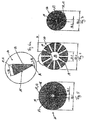
- Fig. 1 shows a first step of the manufacturing process.
- the solid wire which has a circular cross-section, contoured along the radius by the laser beam L, in particular completely severed.
- a plurality of longitudinal slots 18 are introduced, so that the webs 11 of the peripheral wall 10 are cut free.
- the laser beam L penetrates the starting material radially, in particular along several radii.
- the starting material can be severed by the laser beam L star-shaped. In this way, the cake piece-like or circular segment-shaped webs 11.
- the laser beam is applied to twelve different radii of the starting material or the peripheral wall 10, so that a total of twelve distributed over the circumference longitudinal slots 18 result.
- the material removal thus takes place up to the middle of the starting material. This avoids a greater cutting depth, which can lead to an inaccurate cutting process. This increases the accuracy and quality of the manufacturing process.
- twelve webs 11 are exposed, which are distributed over the circumference of the peripheral wall 10.
- the distance between the radii along which the laser beam L cuts the material is preferably the same in each case.
- the longitudinal slots 18 are thus distributed at regular intervals over the circumference of the peripheral wall 10 introduced.
- the passage 17 is formed due to the width or diameter of the laser beam L.
- the passage 17 has an inner circumference in the fully compressed state of the circumferential wall 10, which is a multiple of the beam width of the Laser beam L corresponds.
- the circumference of the through-channel 17 is substantially equal to twelve times the beam width of the laser beam L. This includes the width of the inner edges 16, which also contribute to the circumference of the through-channel 16.
- Fig. 2 shows the medical implant after machining with the cutting tool.
- Well recognizable are the cake piece-like webs 11 of the peripheral wall 10 and the passageway 17 resulting from the manufacturing process.
- the webs 11 of the peripheral wall 10 are preferably post-processed to have a desired surface finish.
- the webs 11 of the peripheral wall 10 are polished or etched to compensate for surface inaccuracies or roughness.
- the webs 11 lose further material, so that the cross-sectional area of the webs 11 is reduced overall.
- Fig. 3 shows the peripheral wall 10 with webs 11 after the polishing step.
- Fig. 4 illustrates the behavior of the peripheral wall 10 in use.
- Fig. 4 a cross-sectional view of the peripheral wall 10 and generally of the implant or stent in the fully compressed state.
- the inner representation corresponds to Fig. 4 according to the representation Fig. 3
- Fig. 4 a cross-sectional view of the peripheral wall 10 in the fully expanded state.
- the superimposed representation in which the completely compressed and the completely expanded peripheral wall 10 are arranged concentrically with one another, clearly illustrates that the implant according to the invention can be compressed from a comparatively large expanded cross-sectional diameter to an extremely small, compressed cross-sectional diameter.
- the implant according to the invention can be guided via small feeders to the treatment site.
- the preferred dimensions of the medical implant are determined by considering the Fig. 5-7 clear. This shows different dimensions of the implant.
- Fig. 5 shows the peripheral wall 10 and the implant in the compressed state immediately after processing with the cutting tool, in particular the laser beam L.
- the peripheral wall 10 has an outer diameter OD-1.
- the passageway 17, which results through the longitudinal slots 18 striking the center, has an inner diameter ID-1.
- the inner diameter ID-1 and the outer diameter OD-1 are so before the post-processing, in particular before the surface treatment of the webs 11, specifically the polishing of the webs 11, determined.
- the through-passage 17 preferably has an inner diameter ID-1 which is at most 0.1 mm, in particular at most 0.06, in particular at most 0.045 mm, in particular at most 0.03 mm.
- the inner diameter ID-1 of the through-channel 17 immediately after the insertion of the longitudinal slots 18 into the starting material is influenced in particular by the beam width or the width of the laser beam L and / or the beam shape of the laser beam L.
- the peripheral wall 10 at this stage of the manufacturing process i. immediately after the introduction of the laser slits 18 into the starting material, an outer diameter OD-1 which is at most 1.1 mm, in particular at most 0.9 mm, in particular at most 0.8 mm, in particular at most 0.5 mm, in particular at most 0, 4 mm, in particular at most 0.3 mm, in particular at most 0.2 mm.
- the outer diameter OD-1 of the circumferential wall 10 is influenced in particular by the choice of the starting material. Concretely, the outer diameter OD-1 may correspond to the wire diameter of the solid wire used, which is the starting material for the production of the peripheral wall 10.
- the implant After the post-processing step, which is intended to influence the surface structure of the webs 11, in particular after the polishing of the webs 11, the implant has changed dimensions in the completely compressed state.
- the through-channel 17 may have an inner diameter ID-2 which is at most 0.105 mm, in particular at most 0.065 mm, in particular at most 0.05 mm, in particular at most 0.035 mm. Because of the material removal during polishing of the webs 11 so the inner diameter ID-2 of the through-channel 17 increases after polishing. Conversely, the outer diameter OD-2 of the peripheral wall 10 may be reduced after polishing.
- the outer diameter OD-2 of the peripheral wall 10 after polishing the webs 11 at most 0.9 mm, in particular at most 0.88 mm, in particular at most 0.78 mm, in particular at most 0.38 mm, in particular at most 0 28 mm, in particular at most 0.18 mm, in particular at most 0.13 mm.
- the enlargement of the inner diameter ID-2 and the outer diameter OD-2 is achieved by the post-processing method used, in particular the polishing method used, affected.
- the outer diameter OD-2 is reduced by the polishing by at most 0.2 mm, in particular at most 0.15 mm, in particular at most 0.1 mm, in particular at most 0.05 mm, in particular at most 0.1 mm, in particular at most 0.05 mm, in particular at most 0.02 mm.
- the inner diameter ID-2 of the through-channel 17 after polishing preferably increases by at most 0.005 mm, in particular at most 0.0025 mm, in particular at most 0.002 mm with respect to the inner diameter ID-1 before polishing.
- the wall thickness W of the peripheral wall 10, which essentially corresponds to the web thickness of the webs 11, is in preferred embodiments at most 0.15 mm, in particular at most 0.1 mm, in particular at most 0.075 mm, in particular at most 0.05 mm, in particular at most 0, 03 mm.
- the wall thickness W is influenced by the choice of the starting material, by the width or transverse extent of the laser beam L and / or by the beam shape of the laser beam L. Considerable influence on the wall thickness W also has the choice of the post-processing process.
- Fig. 6a shows a cross-sectional view of a single web 11 in detail. It can be seen that the web 11 has a web width S-ID at the inner diameter of the passage channel 17 and a deviating web width S-OD at the outer diameter of the peripheral wall 10.
- the web width S-ID at the inner diameter is preferably at most 0.075 mm, in particular at most 0.05 mm, in particular at most 0.03 mm, in particular at most 0.015 mm, in particular at most 0.01 mm, in particular at most 0.009 mm, in particular at most 0.0075 mm ,
- the choice of the starting material, the beam width and / or beam shape of the laser beam L, the type of post-processing and the angle of the flanks, ie the angle which the two side surfaces 14 have influence the web width S-ID at the inner diameter of the through-channel 17 , 15 of the bridge 11 with each other.
- the latter is influenced in particular by the number of webs 11 over the circumference of the circumferential wall 10. Specifically, the first and second side surface 14, 15 to each other at an angle which is greater, the fewer webs 11 are arranged distributed over the circumference of the peripheral wall 10.
- the web width S-OD at the outer diameter of the circumferential wall 10 is in preferred embodiments at most 0.15 mm, in particular at most 0.1 mm, in particular not more than 0.09 mm, in particular not more than 0.08 mm, in particular not more than 0.07 mm, in particular not more than 0.05 mm, in particular not more than 0.03 mm, in particular not more than 0.025 mm.
- the web width S-OD on the outer diameter of the peripheral wall 10 and the cylindrical surface 13 is mainly by the choice of finishing steps, such as the choice of polishing process, and / or the angle of the flanks or the side surfaces 14, 15 to each other, ie the number of webs 11 along the circumference of the peripheral wall 10, influenced.
- the inner diameter ID-1 and the outer diameter OD-2 are preferably in a particular relationship to one another in order to provide the sufficient radial force for the implant on the one hand and to achieve the lowest possible compressed cross-sectional diameter before reworking or polishing the peripheral wall 10.
- the ratio ID-1 / OD-1 between the inner diameter ID-1 of the through-channel 17 and the outer diameter OD-1 of the peripheral wall 10 or the cylinder jacket surface 13 before re-machining or polishing the peripheral wall 10 is at most 1 / 40, in particular at most 1/20, in particular at most 1/10, in particular at most 1/5, in particular at most 1/2.
- the ratio ID-2 / OD-2 between the inner diameter ID-2 of the through-channel 17 and the outer diameter OD-2 of the peripheral wall 10 after the post-processing step (after polishing), i. in the finished state at most 1/20, in particular at most 1/10, in particular at most 1/5, in particular 1/2.
- FIG. 7 shows a cross-sectional view through the implant or the stent according to FIG. 6 in the fully compressed state. It can be clearly seen that the webs 11 lie flush against each other or the entire surface. In this respect, the implant yields in the fully compressed state FIG. 7 a smaller outer diameter OD-3 than in the manufacturing state according to FIG. 6 on.
- the outer diameter OD-3 of the circumferential wall 10 in the fully compressed state is preferably at most 0.87 mm, in particular at most 0.85 mm, in particular at most 0.75 mm, in particular at most 0.35 mm, in particular at most 0.28 mm, in particular at most 0.25 mm, in particular at most 0.15 mm, in particular at most 0.1 mm.
- the inner diameter ID-3 of the peripheral wall 10 is in the fully compressed state according to FIG. 7 smaller than in the manufacturing state according to FIG. 6 .
- a laser beam L that is parallel to one another is used for the formation of the longitudinal slots 18 that penetrate the starting material.
- the laser beam L has a substantially constant beam cross-section.
- the laser beam L has a beam cross-section which widens in the direction of the center of the peripheral wall 10.
- FIGS 8 and 9 An exemplary embodiment for the production of the medical implant with a laser beam L that widens up to the center of the peripheral wall 10 is shown in FIGS 8 and 9 shown.
- FIG. 8 shows the laser beam L at different radii of the peripheral wall 10 and the starting material, from which the peripheral wall 10 is formed. It can be clearly seen that the inner diameter D-1 of the through-channel 17 increases in the compressed state of the circumferential wall 10 as a result of the laser beam L expanding with increasing proximity to the center of the peripheral wall 10 compared with a production method in which a laser beam L with parallel beam guidance is used becomes. At the same time, the ratio between the web width S-OD at the outer diameter and the web width S-ID at the inner diameter is reduced compared with a production method in which a laser beam L with parallel beam guidance is used. Consequently, the wall thickness W is smaller when using a laser beam L with widening beam guidance than when using a laser beam L with parallel beam guidance.
- FIG. 9 shows the implant according to Fig. 8 wherein the peripheral wall 10 has been polished. The polishing results in the rounding of the inner edge 16 of the webs 11th
- the starting material in particular a solid wire, is preferably subdivided into a plurality of longitudinal sections.
- Each of the longitudinal sections comprises a plurality of longitudinal slots 18.
- the longitudinal slots 18 are preferably distributed in the longitudinal sections at regular intervals over the circumference of the peripheral wall 10 and penetrate the starting material or the peripheral wall 10 completely.
- the longitudinal slots 18 of adjacent circumferential segments are preferably arranged offset from one another, so that the overall result is an integrally connected circumferential wall 10.
- the offset of the longitudinal slots 18 adjacent longitudinal sections is preferably carried out in the circumferential direction.
- the sum of the lengths of the longitudinal slots 18 corresponds to the total length of the circumferential wall 10.
- the laser beam L When cutting takes place by means of the laser beam L, the laser beam L or a first laser beam L extends like a spoke to the center of the solid material, in particular the solid wire, to form a side surface 14, 15 of the web 11.
- the other side surface 15, 14 is formed by a extending to the center of the solid material, in particular the solid wire, second laser beam L, which intersects the beam path of the first laser beam L.
- the intersection of the laser beams L is preferably in the longitudinal axis of the peripheral wall 10.
- the first and second laser beam L can process the material simultaneously or in succession.
- Fig. 10 shows a perspective view of a medical device having a distal end portion 19 which is formed substantially analogous to the previously described in detail implant.
- the distal end portion 19 is formed integrally or monolithically with a proximal transport element 20.
- the transport element 20 is formed in the present embodiment as a hollow wire, but may also have a solid material.
- the distal end portion 19 forms a peripheral wall 10 which is radially expandable.
- the peripheral wall 10 is formed of a plurality of webs 11 which are shaped like a cake piece.
- the entire device is according to Fig. 10 from a single raw material, for example a hollow wire or a solid wire.
- longitudinal slots 18 are introduced in the manufacture, which are each arranged offset from one another in such a way that a grid structure 21 is formed.
- the grid structure 21 is expandable and integrally connected to the transport element 20.
- the apparatus shown can be used, for example, as a thrombectomy device, ie for removing thrombi from blood vessels. Further possible uses of devices designed according to the invention are blood filters.
- the medical device or the medical implant according to the invention is suitable for use in blood vessels.
- Fig. 11 shows a cross section through the peripheral wall 10 of a medical device or a medical implant according to the invention.
- the illustration corresponds to Fig. 11 according to the representation Fig. 4 , wherein the peripheral wall 10 is shown in the expanded state.
- the peripheral wall is formed of a composite material.
- the composite material includes two or more material components 22, 23 that differ in radiopacity and / or electrical conductivity.
- the expandable peripheral wall is made of a single wire, which is formed as a composite wire, that has a composite material.
- the wire may comprise a core wire made of a first material component 22 and a sheath made of a second material component 23.
- the first material component 22 preferably has a higher radiopacity than the second material component 23. In this way results in a peripheral wall 10, which is constructed in multiple layers, wherein the individual layers are arranged concentrically or coaxially to each other.
- Fig. 12 shows in detail a cross section through a web 11 of the peripheral wall 10 according to Fig. 11 , It can be clearly seen that the web 11 has a first material component 22 and a second material component 23. The first material component 22 is arranged radially inside the second material component 23. Furthermore, it is off Fig. 12 clearly seen that the side surfaces 14, 15 of the web 11 converge to each other and are connected to each other on an inner periphery of the peripheral wall 10 by an inner surface 24. In other words, the web 11 forms a cake-like cross-section with a flattened tip, wherein the flattened tip is formed by the inner surface 24. For reasons of clarity, in the schematic representation of the web 11 according to Fig. 12 the rounding of the edges is not shown.
- peripheral wall 10 With reference to the FIGS. 11 and 12 In the following some preferred dimensions of the peripheral wall 10 are given, which generally apply to all embodiments of the invention.
- the peripheral wall 10 in the expanded state preferably has an outer diameter OD EXP which is between 2.5 mm and 8 mm, in particular between 3 mm and 7 mm, in particular between 3.5 mm and 6 mm, in particular 4.5 mm.
- the ratio between the wall thickness W of the circumferential wall 10 or the web thickness and the outer diameter OD EXP of the peripheral wall 10 in the expanded state, ie the ratio W / D, is preferably between 0.00625 and 0.04, in particular between 0.008 and 0.03 , in particular 0.01 to 0.02.
- the distance between the outer surface 12 of the web 11 and an intersection of the side surfaces 14, 15 is referred to as cutting depth r.
- the cutting depth r corresponds to the ratio between half the diameter of a catheter through which the device or the implant can be pushed, and the outer diameter of the circumferential wall 10 in the expanded state.
- the ratio between the cutting depth r and the outer diameter OD EXP of the circumferential wall 10 in the expanded state, ie the ratio r / D, is preferably between 0.025 and 0.08, in particular between 0.03 and 0.06, in particular between 0.04 and 0.05.
- the outer diameter of the wire, from which the peripheral wall 10 is produced by laser cutting is r uncut in the double depth of cut r.
- the outer diameter of the wire, which is used for the production of the peripheral wall 10 (2 ⁇ r) between 0.2 mm and 0.5 mm, in particular between 0.3 mm and 0.4 mm.
- Fig. 12 shows the web 11 with an inner surface 24.
- the web 11 has an inner edge 16 which connects the two side surfaces 14, 15 directly to each other.
- the inner edge 16 may be completely rounded, so that the inner edge 16 is slimmed with an inner surface 24.
- the jetty according to Fig. 12 has two material components 22, 23. These each form a material layer, the layer thickness a of the first material component 22 preferably being between 5 ⁇ m and 20 ⁇ m, in particular between 6 ⁇ m and 15 ⁇ m, in particular between 8 ⁇ m and 12 ⁇ m, preferably 10 ⁇ m.
- the total web thickness or wall thickness W is preferably between 30 ⁇ m and 100 ⁇ m, in particular between 40 ⁇ m and 80 ⁇ m, in particular between 50 ⁇ m and 70 ⁇ m, preferably 60 ⁇ m.
- the ratio between the layer thickness a of the first material component 22 and the wall thickness W is preferably between 5% and 40%, in particular between 10% and 30%, in particular between 15% and 25%, preferably 20%.
- the abovementioned values apply in particular if the first material component 22 has a radiopaque material or has a higher radiopacity than the second material component 23.
- the first material component 22 is disposed on an inner periphery of the peripheral wall 10. It is also possible that the first material component, preferably including the aforementioned dimensions of the layer thickness a, is located on an outer circumference of the circumferential wall 10.
- the arrangement of the first material component 22 on the outer circumference is particularly preferred when the first material component 22 has a higher electrical conductivity than the second material component 23.
- the first material component 22 may form an intermediate layer which is embedded between two further layers.
- the intermediate layer may comprise an electrically insulating material.
- the first material component 22 is then preferably arranged on the outer circumference and through the intermediate layer of the second material component 23 separated, which is arranged on the inner circumference and assumes a supporting function.
- the wire from which the peripheral wall 10 is cut has a volume ratio between the first material component 22 and the second material component 23 that is between 10% and 50%, in particular between 12% and 40%, in particular between 15% and 30%. , preferably 20%.
- the first material component 22 is provided with a higher radiopacity than the second material component 23.
- the web width S-OD at the outer diameter of the circumferential wall 10 is preferably between 20 ⁇ m and 75 ⁇ m, in particular between 22 ⁇ m and 50 ⁇ m, in particular between 25 ⁇ m and 45 ⁇ m, in particular between 30 ⁇ m and 40 ⁇ m.
- the web width S-ID at the inner diameter of the peripheral wall 10 is preferably between 10 .mu.m and 50 .mu.m, in particular between 15 .mu.m and 30 .mu.m, in particular between 18 .mu.m and 25 .mu.m.
- the above-mentioned values preferably correspond to the maximum possible rounding on the inner circumference of the peripheral wall 10.
- the ratio between the web width S-ID inner diameter of the circumferential wall 10 to the web width S-OD on the outer surface 12 of the peripheral wall 10, ie the ratio S-ID / S-OD , is preferably less than 0.8, in particular less than 0.6, in particular less than 0.4, in particular less than 0.3, but greater than 0.1.
- Fig. 12 also shows an intermediate width p, which corresponds to the web width in the region of the transition between the two material components 22, 23.
- the intermediate width p is preferably between 20 ⁇ m and 60 ⁇ m, in particular between 25 ⁇ m and 35 ⁇ m.
- the ratio p / S-OD between the intermediate width p and the web width S-OD at the outer diameter of the circumferential wall 10 is preferably less than 0.8, in particular less than 0.7, in particular less than 0.6, in particular less than 0.5 , but greater than 0.2.
- Fig. 13 is a plan view of a portion of a grid structure 21, which is produced by the method according to the invention.
- the grid structure 21 has a plurality of webs 11, the cells 25 limit.
- the webs 11 have a cake-piece-like cross-sectional shape.
- Fig. 14a For example, a cross section of the web 11 along the line AA in Fig. 13 , It can be seen that the web 11 has two material components 22, 23, wherein a first material component 22 with a relatively higher radiopacity is arranged radially inside the second material component 23 with the relatively lower radiopacity. Essentially, the lattice structure 21 or peripheral wall 10 is thus formed in two layers, wherein a radially inner layer has a higher radiopacity than a radially outer layer.
- Fig. 14b shows a sectional view through the grid structure 21 along the line BB in Fig. 13 , Due to the coincidence of a plurality of webs 11 in the region of a connection point 26 of the lattice structure 21, the cross-sectional view according to FIG Fig. 14b a flattened tip of the per se cake piece-like cross-section.
- Fig. 14c shows a longitudinal sectional view of the peripheral wall 10 along the line CC in Fig. 13 , It can easily be seen that the individual webs 11 are formed entirely from two material components 22, 23. The two material components 22, 23 together form a composite material.
- Fig. 15 shows an X-ray of the lattice structure section according to Fig. 13 .
- the radiopacity is influenced in particular by the material volume of the first material component 22.
- a smaller volume of material of the first material component 22 is present in the region of the webs 11 because of the cake-like cross-sectional shape than in the region of the junction 26.
- the junction 26 is therefore better visible under X-radiation than the webs 11.
- the radiopacity can thus over the entire peripheral wall 10 different Be pronounced.
- an implant or a device which in each case has at least one web 11 which has a cake-piece-shaped cross-sectional shape.
- a tip of the cake-piece-like cross-sectional shape is directed inwards.
- the side surfaces 14, 15 of the web 11 converge radially inwardly to a longitudinal axis of the peripheral wall 10.
- the web 11 at least two material components 22, 23, wherein a first material component 22 has a higher radiopacity than a second material component 23. It is also possible that the first material component has a higher electrical conductivity than the second material component 23.
- the first material component 22 with the higher radiopacity is disposed radially within the second material component 23.
- the implant or the device may have a plurality of webs 11.
- the webs 11 together form a peripheral wall 10 and a grid structure 21.
- the peripheral wall 10 and the grid structure 21 is radially expandable.
- the webs 11 extend mainly in the longitudinal direction of the peripheral wall 10 or helically around a longitudinal axis of the peripheral wall 10.
- Such a configuration of the peripheral wall 10 is particularly suitable for blood filters and Thrombectomiedevices.
- the webs 11 can generally form a lattice structure, which is advantageous in particular for the use of the medical device as a stent, flow diverter or thrombectomy device.
- a part of the medical device may be unstructured, that is not be processed by laser cutting.
- Such a region of the device preferably forms a transport element, which is formed substantially diameter-stable.
- a distal end portion 19, which is formed as an expandable peripheral wall 10 are guided to the treatment location.
- a medical device, which is intended for temporary use in blood vessels and has a radially expandable distal end portion 19 and a proximal, diameter-stable portion serving as a transport element 20 can be used in particular as Thrombectomiedevice, blood filter or as an electrode for stimulation or ablation.
- a medical device can be formed, which is formed of a plurality of longitudinal axial successively arranged, expandable peripheral walls 10. Between the individual peripheral walls 10 articulated elements can be arranged.
- the hinge-like elements may be formed by diameter-stable sections.
- the entire medical device is monolithically formed, wherein the expandable peripheral walls 10 or lattice structures 21 are produced by structuring a single output wire.
- the implant according to the invention or the device according to the invention are preferably insertable into the human body via a catheter whose inside diameter is at most 0.7 mm, in particular at most 0.51 mm, in particular at most 0.42 mm.
- the invention is also applicable to medical devices that are temporarily inserted in a body cavity.
- the invention is also applicable to thrombectomy devices or blood filters having an expandable portion.
- the expandable portion is similar to the implant structure described in detail herein and fixed, in particular monolithic, connected to a transport element, such as a guide wire.
- the expandable portion preferably forms a distal end portion of the transport element.
- the transport element may be formed as a solid wire or as a hollow wire. Overall, the entire medical device can be formed monolithically from a solid or hollow wire.
- the solid or hollow wire may consist of a composite material containing at least two different material components.
- a core wire can be provided with a sheath, wherein the core wire contains a first material component and the sheath contains a second material component.
- the first material component may have a higher radiopacity and / or electrical conductivity than the second material component.
- the grid structure 21 has webs 11 and cells 25, wherein the webs 11 completely delimit the cells 25.
- the number of cells 25 in the circumferential direction of the lattice structure 21 may be different. In particular, the number of cells can be adjusted depending on the intended use of the implant or the device.
- the number of cells 25 in the circumferential direction between 3 and 12, in particular between 4 and 9, preferably 6, amount.
- Such a number of cells is suitable for the protection of intracranial aneurysms.
- the number of cells 25 in the circumferential direction between 6 and 24, in particular between 9 and 18, preferably 12, amount.
- a number of cells between 4 and 16, in particular between 6 and 12, preferably 9, has proved to be advantageous.
- a circumferential wall 10 may also be provided, which has longitudinally and / or helically extending webs 11 extending around the longitudinal axis of the circumferential wall 10.
- the peripheral wall 10 preferably forms between 4 and 24, in particular between 6 and 18, in particular between 9 and 12, cells in the circumferential direction.
Landscapes
- Health & Medical Sciences (AREA)
- Engineering & Computer Science (AREA)
- Biomedical Technology (AREA)
- Life Sciences & Earth Sciences (AREA)
- Transplantation (AREA)
- Oral & Maxillofacial Surgery (AREA)
- Heart & Thoracic Surgery (AREA)
- Vascular Medicine (AREA)
- Cardiology (AREA)
- Animal Behavior & Ethology (AREA)
- General Health & Medical Sciences (AREA)
- Public Health (AREA)
- Veterinary Medicine (AREA)
- Physics & Mathematics (AREA)
- Optics & Photonics (AREA)
- Prostheses (AREA)
Description
- Die Erfindung betrifft ein medizinisches Implantat, ein Behandlungssystem mit einem derartigen Implantat sowie ein Verfahren zum Herstellen eines medizinischen Implantats.
- Medizinische Implantate mit einer radial komprimierbaren und radial expandierbaren Umfangswandung, beispielsweise Stents, werden meist aus einem Geflecht aus Drähten oder einer Zellenstruktur gebildet, wobei die Zellen durch Stege begrenzt sind. Die Stege sind einstückig miteinander verbunden und bilden so die Umfangswandung, deren Querschnittsdurchmesser variabel ist. Die Herstellung von aus Stegen gebildeten Umfangswandungen erfolgt durch einen schneidenden Prozess, wobei ein Röhrchen bereitgestellt wird, aus dessen Wandung die Zellen der herzustellenden Umfangswandung ausgeschnitten werden. Durch das Ausschneiden der Zellen werden die Stege gebildet, die eine rechteckige oder trapezförmige Querschnittskontur aufweisen.
- Die trapezförmige Querschnittskontur der Stege begrenzt die Komprimierbarkeit. Der kleinstmögliche komprimierte Querschnittsdurchmesser entspricht im Wesentlichen dem Querschnittsdurchmesser des Röhrchens, das die Vorlage für den Stent bildet. Das Röhrchen muss jedoch einen Mindestdurchmesser aufweisen, um einerseits die gewünschte Wandstärke für den Stent bereitzustellen und andererseits einen Durchgangskanal offen zu lassen, der das Röhrchen in Längsrichtung durchdringt.
- Bei der Herstellung eines Implantats aus einem Röhrchen ergibt sich die Schwierigkeit, dass das Röhrchen wegen der meist gewünschten geringen Wandstärke, vergleichsweise instabil ist. Dies stellt hohe Anforderungen an eine Halterung bzw. Lagerung dar. Das entsprechende Werkzeug zur schneidenden Bearbeitung des Röhrchens ist daher so auszulegen, dass die Röhrchenform beim Greifen des Röhrchens nicht verändert, gleichzeitig aber das Röhrchen ausreichend fest gehalten wird, um die Zellen aus der Wandung des Röhrchens auszuschneiden.
-
DE 197 22 429 A1 beschreibt eine Vorrichtung zum Entfernen von Gallensteinen. Die Vorrichtung umfasst ein expandierbares Fangelement, das durch Längsschnitte in einem Draht gebildet ist, wobei der Draht im Gebrauch aus dem Körper eines Patienten führt, um ein Herausziehen des Fangelements zu ermöglichen. Nachteilig ist bei der bekannten Vorrichtung, dass die Bewegung und Anordnung des Fangelements innerhalb des Körpers des Patienten wegen eingeschränkter röntgensichtbarer Eigenschaften nur schwer beobachtet und kontrolliert werden kann. Außerdem eignet sich die Vorrichtung nicht zum Verbleib innerhalb des Körpers und ist daher nicht als Implantat einsetzbar. - Der Erfindung liegt die Aufgabe zugrunde, ein medizinisches Implantat anzugeben, das sich einfach herstellen lässt und einen möglichst kleinen komprimierten Querschnittsdurchmesser aufweist. Ferner ist es Aufgabe der Erfindung, ein Behandlungssystem mit einem derartigen Implantat und ein Verfahren zum Herstellen eines medizinischen Implantats anzugeben.
- Erfindungsgemäß wird diese Aufgabe im Hinblick auf das medizinische Implantat durch den Gegenstand des Patentanspruchs 1, im Hinblick auf das Behandlungssystem durch den Gegenstand des Patentanspruchs 5 und im Hinblick auf das Verfahren durch den Gegenstand des Patentanspruchs 6 gelöst.
- So beruht die Erfindung auf dem Gedanken, ein medizinisches Implantat mit einer radial komprimierbaren und radial expandierbaren kreiszylinderförmigen Umfangswandung anzugeben, die einstückig aus Stegen gebildet ist. Die Stege weisen (im Wesentlichen) eine kuchenstückartige Querschnittsform auf.
- Die nachfolgende Erfindungsbeschreibung erläutert bevorzugte Ausgestaltungen der konstruktiven Gestaltung des medizinischen Implantats. Diese Merkmale des medizinischen Implantats gelten gleichermaßen für eine medizinische Vorrichtung, beispielsweise ein Thrombektomiedevice, ein Flow Diverter oder einen Blutfilter. Derartige Vorrichtungen weisen üblicherweise einen expandierbaren Abschnitt auf, der sich analog zu dem hier detailliert beschriebenen Implantat verhält. Der expandierbare Abschnitt ist fest, insbesondere monolithisch, mit einem Transportelement verbunden bzw. bildet einen distalen Endabschnitt des Transportelements.
- Durch die kuchenstückartige Querschnittsform der Stege lässt sich das erfindungsgemäße medizinische Implantat bzw. dessen kreiszylinderförmige Umfangswandung auf einen besonders kleinen Querschnittsdurchmesser komprimieren. Das erleichtert die Zuführung des medizinischen Implantats in kleine Körperhohlorgane, beispielsweise in kleine Blutgefäße. Im implantierten Zustand bietet die Querschnittsform des medizinischen Implantats zudem einen äußerst geringen Strömungswiderstand, so dass eine Fluidströmung in den Körperhohlorganen kaum beeinflusst wird.
- Überdies ist die Herstellung des erfindungsgemäßen medizinischen Implantats vereinfacht, da als Ausgangsmaterial kein Röhrchen, sondern ein Vollmaterial verwendet wird. Somit können Materialungenauigkeiten, beispielsweise eine unregelmäßige Oberflächenbeschaffenheit, die bei röhrchenförmigen Ausgangsmaterialien auf der Innenumfangsfläche auftreten können, vermieden werden. Das erfindungsgemäße medizinische Implantat weist daher eine besonders hohe Fertigungsgenauigkeit auf.
- Erfindungsgemäß weisen die Stege der kreiszylinderförmigen Umfangswandung jeweils eine gekrümmte Außenfläche auf, die im komprimierten Zustand der Umfangswandung eine äußere Zylindermantelfläche der Umfangswandung bildet. In diesem Zusammenhang wird darauf hingewiesen, dass der radial komprimierte Zustand der Umfangswandung den maximal komprimierten Zustand beschreibt, soweit nichts anderes angegeben ist. Entsprechend bezeichnet der radial expandierbare Zustand der kreiszylinderförmigen Umfangswandung den maximal expandierten Zustand, falls nichts anderes angegeben ist.
- Durch die gekrümmte Außenfläche der Stege, deren Krümmungsradius (im Wesentlichen) dem Krümmungsradius der äußeren Zylindermantelfläche der Umfangswandung entspricht, wenn die Umfangswandung im komprimierten Zustand vorliegt, wird eine besonders leichte Zuführung des Implantats über eine Zuführeinrichtung erreicht. Im komprimierten Zustand weist die Umfangswandung eine gleichmäßige, kreiszylinderförmige Mantelfläche auf, so dass sich das Implantat leicht durch den kreiszylinderförmigen, inneren Durchgangskanal einer Zuführeinrichtung, beispielsweise eines Katheters, führen lässt.
- Die Stege der Umfangswandung weisen erfindungsgemäß jeweils zwei zur Längsachse der Umfangswandung konvergierende Seitenflächen auf. Die Seitenflächen erstrecken sich parallel zu einem Radius der Umfangswandung.
- Die Seitenflächen der einzelnen Stege verlaufen vorzugsweise derart konvergierend in Richtung der Längsachse der Umfangswandung, dass der jeweilige Steg im Querschnitt im Wesentlichen eine Spitze bildet, die in Richtung des Zentrums der Umfangswandung zeigt. Die Spitze entspricht der Kuchenstückspitze der kuchenstückartigen Querschnittsform. Vorzugsweise erstrecken sich die Seitenflächen parallel zum Radius der Umfangswandung, insbesondere entlang des Radius der Umfangswandung. Das hat den Vorteil, dass die Seitenflächen benachbarter Stege im komprimierten Zustand der Umfangswandung aneinander flächig anliegen können und sich somit die Stege vollflächig gegeneinander abstützen können. Das erhöht die Stabilität der Umfangswandung im komprimierten Zustand.
- Alternativ kann vorgesehen sein, dass die Seitenflächen unmittelbar benachbarter Stege in Richtung zum Außenumfang der Umfangswandung zueinander konvergieren. Unbeschadet davon, wie die Seitenflächen unmittelbar benachbarter Stege zueinander ausgerichtet sind, konvergieren die Stege eines einzelnen Stegs in Richtung zur Längsachse der Umfangswandung.
- Erfindungsgemäß weisen die Stege bei dem erfindungsgemäßen Implantat bzw. der erfindungsgemäßen Vorrichtung jeweils eine (einzelne) Innenkante auf, die die Seitenflächen verbindet. Die Innenkante ist radial innerhalb der äußeren Zylindermantelfläche angeordnet und bildet eine Spitze der kuchenstückartigen Querschnittsform der Stege.
- Mit anderen Worten treffen sich die zur Längsachse konvergierenden Seitenflächen an der Innenkante der Stege. Die Innenkante erstreckt sich vorzugsweise in Längsrichtung der Umfangswandung bzw. weist zumindest eine Hauptrichtungskomponente auf, die in Längsrichtung der Umfangswandung orientiert ist.
- Bei einer bevorzugten Ausführungsform des medizinischen Implantats begrenzen die Stege, insbesondere die Innenkanten der Umfangswandung einen kreiszylinderförmigen Durchgangskanal. Das Verhältnis zwischen einem Innendurchmesser des Durchgangskanals und einem Außendurchmesser der Umfangswandung, insbesondere der Zylindermantelfläche, kann im komprimierten Zustand der Umfangswandung höchstens 1/20, insbesondere höchstens 1/10, insbesondere höchstens 1/7, insbesondere höchstens 1/2, betragen. Im expandierten Zustand der Umfangswanderung kann das Verhältnis zwischen Innendurchmesser und Außendurchmesser höchstens 1/100, insbesondere höchstens 1/80, insbesondere höchstens 1/60, insbesondere höchstens 1/40, betragen. Die Stege der Umfangswandung können eine Stegdicke bzw. die Umfangswandung kann eine Wandstärke aufweisen, die höchstens 0,15 mm, insbesondere höchstens 0,1 mm, insbesondere höchstens 0,075 mm, insbesondere höchstens 0,05 mm, insbesondere höchstens 0,03 mm, beträgt. Mit den zuvor genannten Werten sind medizinische Implantate herstellbar, die einerseits eine ausreichende Wandstärke aufweisen, um ein Blutgefäß sicher zu stützen und andererseits einen äußerst kleinen Querschnittsdurchmesser im komprimierten Zustand aufweisen, um in kleine Blutgefäße, beispielsweise cerebrale Blutgefäße, eingesetzt zu werden.
- Vorzugsweise sind alle Stege der Umfangswandung, die in Umfangsrichtung und/oder Längsrichtung benachbart zueinander angeordnet sind, gleichartig ausgebildet. Insbesondere sind alle Stege der Umfangswandung gleichartig ausgebildet, weisen also eine kuchenstückartige Querschnittsform auf. Dabei kann die Umfangswandung grundsätzlich aus mehreren Stegen gebildet sein, die in Umfangsrichtung zueinander gleichmäßig beabstandet angeordnet sind. Insbesondere kann die Umfangswandung mehrere Längsabschnitte aufweisen, die jeweils durch eine Reihe von in Umfangsrichtung benachbart angeordneten Stegen umfassen. Die Stege in Längsrichtung benachbarter Längsabschnitte sind vorzugsweise in Umfangsrichtung zueinander versetzt angeordnet, insbesondere so dass jeweils ein Steg eines ersten Längsabschnitts mit zwei Stegen eines benachbarten zweiten Längsabschnitts der Umfangswandung verbunden ist.
- Bei der Erfindung ist ferner vorgesehen, dass die Stege jeweils ein Verbundmaterial aufweisen, das aus wenigstens zwei Materialkomponenten gebildet ist. Die zwei Materialkomponenten weisen unterschiedliche Röntgensichtbarkeit und/oder unterschiedliche elektrische Leitfähigkeit auf.
- Insbesondere kann eine erste Materialkomponente eine höhere Röntgensichtbarkeit oder elektrische Leitfähigkeit als eine zweite Materialkomponente aufweisen. Durch die Verwendung eines Verbundmaterials kann eine vorteilhafte Erhöhung der Röntgensichtbarkeit erreicht werden, obwohl die Stege wegen der kuchenstückartigen Querschnittsform eine reduzierte, sichtbare Fläche bieten. Durch eine geeignete Materialkombination kann dies ausgeglichen werden. Beispielweise kann die Umfangswandung durch Laserschneiden aus einem Verbunddraht hergestellt sein, der einen Kerndraht aus einer ersten Materialkomponente und eine Umhüllung aus einer zweiten Materialkomponente aufweist. Der Kerndraht kann eine höhere Röntgensichtbarkeit als die Umhüllung aufweisen. Beispielsweise kann der Kerndraht Platin oder eine Platinlegierung oder Tantal oder eine Tantallegierung aufweisen. Die Verwendung von Platin ist insbesondere zur Erhöhung der elektrischen Leitfähigkeit vorteilhaft. Dabei kann auch die Umhüllung aus Platin oder einer Platinlegierung bestehen. Die Umhüllung kann eine Nickel-Titan-Legierung aufweisen, wobei die Umhüllung im Wesentlichen tragende Eigenschaften hat, also die mechanische Stabilität der Umfangswandung gestaltet. Andere Materialkombinationen sind möglich.
- Gemäß einem nebengeordneten Aspekt beruht die Erfindung auf dem Gedanken, ein Behandlungssystem mit einem zuvor beschriebenen Implantat oder der Vorrichtung und einer Zuführeinrichtung zur Zufuhr des Implantats in ein Körperhohlorgan, insbesondere ein Blutgefäß, anzugeben. Die Zuführeinrichtung kann insbesondere als Katheter ausgebildet sein, der zur Zufuhr in den menschlichen Körper angepasst ist. Das Implantat kann bei dem Behandlungssystem in der Zuführeinrichtung angeordnet sein. Alternativ ist es möglich, dass das Behandlungssystem als Sterilset vorliegt, bei dem sich das Implantat mit der Zuführeinrichtung eine Sterilgutverpackung teilt. Die Zuführeinrichtung kann auch eine Schleuse bilden, die mit einem Katheter verbindbar ist, um die Vorrichtung oder das Implantat an den Katheter zu übergeben.
- Ein weiterer nebengeordneter Aspekt der Erfindung betrifft ein Verfahren zur Herstellung eines medizinischen Implantats, insbesondere des zuvor beschriebenen Implantats, aus einem kreiszylinderförmigen Vollmaterial. Das Vollmaterial wird in wenigstens einem Längsabschnitt mit einem Schneidwerkzeug radial vollständig durchtrennt, so dass eine radial komprimierbare und radial expandierbare Umfangswandung aus Stegen mit einer kuchenstückartigen Querschnittsform gebildet wird.
- Das erfindungsgemäße Verfahren ermöglicht eine erhebliche Erleichterung bei der Herstellung von Implantaten, die zur Zufuhr in kleine Blutgefäße, beispielsweise cerebrale Blutgefäße, angepasst sind. Mit dem erfindungsgemäßen Verfahren wird die Verwendung von röhrchenförmigen Ausgangsmaterialien vermieden. Fertigungstoleranzen, die sich auf den Innendurchmesser von röhrchenförmigen Ausgangsmaterialen auswirken, spielen daher bei dem erfindungsgemäßen Verfahren keine Rolle. Somit ermöglicht das Verfahren eine besonders genaue Herstellung von Umfangswandungen.
- Bei dem erfindungsgemäßen Verfahren werden mit dem Schneidwerkzeug Längsschlitze gebildet, die das Vollmaterial radial vollständig durchdringen. Insbesondere weisen die Längsschlitze eine Länge auf, die kleiner als eine Gesamtlänge des Vollmaterials ist. Konkret ist vorgesehen, das Vollmaterial bzw. Ausgangsmaterial (Vollzylinder) in Längsrichtung, d.h. entlang der Längsachse, in mehrere Abschnitte zu unterteilen. In jeden der Längsabschnitte kann wenigstens ein Längsschlitz eingebracht werden, wobei die Längsschlitze benachbarter Längsabschnitte in Umfangsrichtung des Vollmaterials versetzt zueinander angeordnet werden. Dadurch wird sichergestellt, dass eine zusammenhängende Umfangswandung hergestellt wird.
- Vorzugsweise werden entlang einer Längsachse des Vollmaterials mehrere Längsschlitze ausgeformt, die in Umfangsrichtung versetzt zueinander angeordnet sind.
- Die Längsschlitze werden vorzugsweise in Umfangsrichtung in gleichmäßigen Abständen zueinander in das Vollmaterial eingebracht. Das zwischen den Längsschlitzen stehenbleibende Material bildet die Stege der Umfangswandung. Indem die Längsschlitze in gleichmäßigen Abständen zueinander über den Umfang verteilt angeordnet werden, werden gleichmäßige Stege freigelegt. Für das so hergestellte Implantat ergibt sich der Vorteil, dass durch die Identität der Stege in Umfangsrichtung auch die Radialkraft, die das Implantat auf eine Gefäßwand eines Körperhohlorgans, beispielsweise eines Blutgefäßes, ausübt, gleichmäßig über den gesamten Umfang ist.
- Vorzugsweise ist das Schneidwerkzeug ein Laserstrahl. Damit werden besonders exakte und kleine Längsschlitze in das Vollmaterial eingebracht. Insbesondere ermöglicht der Laserstrahl die Bearbeitung von Vollmaterial, das einen sehr kleinen Querschnittsdurchmesser aufweist.
- Der Laserstrahl kann derart geführt bzw. fokussiert sein, dass sich im Wesentlichen parallele Schnittkanten ergeben. Damit werden Stege freigelegt, deren Seitenflächen parallel zum Radius der Umfangswandung im komprimierten Zustand ausgerichtet sind. Dies begünstigt eine vollflächige Anlage der Seitenflächen benachbarter Stege im komprimierten Zustand der Umfangswandung. Alternativ kann der Laserstrahl eine zum Zentrum des Vollmaterials sich aufweitende Strahlführung aufweisen. Dadurch wird erreicht, dass die Innenkanten der Stege im komprimierten Zustand der Umfangswandung voneinander beabstandet angeordnet sind. Es besteht somit keine vollflächige, sondern vielmehr linienartige Berührung zwischen den Stegen. Insbesondere berühren sich die Stege im Bereich des Außenumfangs der Umfangswandung, wenn die Umfangswandung komprimiert ist.
- In bevorzugter Weise ist vorgesehen, dass die Stege der Umfangswandung bzw. allgemein die Umfangswandung anschließend, insbesondere nach der Bearbeitung mit dem Schneidwerkzeug, poliert werden bzw. wird. Auf diese Weise wird eine besonders glatte Oberfläche der Stege hergestellt, so dass der Einfluss des Implantats auf eine Fluidströmung in einem Blutgefäß weiter reduziert wird.
- Das Vollmaterial, aus welchem die expandierbare Umfangswandung gebildet wird, ist ein Verbundmaterial, das wenigstens zwei Materialkomponenten aufweist. Die Materialkomponenten weisen unterschiedliche Röntgensichtbarkeiten und/oder elektrische Leitfähigkeiten auf. Vorzugsweise weist eine erste Materialkomponente eine höhere Röntgensichtbarkeit und/oder elektrische Leitfähigkeit als eine zweite Materialkomponente auf. Durch das Schneiden des Verbundmaterials entstehen einzelne Stege, die jeweils aus wenigstens zwei Schichten aufgebaut sind, wobei jede Schicht eine Materialkomponente bildet. Vorzugsweise sind die Schichten bzw. Materialkomponenten mit Bezug auf eine Längsachse der Umfangswandung konzentrisch zueinander angeordnet.
- Die Erfindung wird im Folgenden anhand von Ausführungsbeispielen unter Bezugnahme auf die beigefügten, schematischen Zeichnungen näher erläutert. Darin zeigen
-
Fig. 1-3 jeweils eine Querschnittsansicht eines medizinischen Implantats nach einem bevorzugten Ausführungsbeispiel in unterschiedlichen Herstellungsstadien; -
Fig. 4 eine kombinierte Querschnittsdarstellung des medizinischen Implantats gemäßFig. 1-3 sowohl im Herstellzustand, als auch im vollständig expandierten Zustand; -
Fig. 5 eine Querschnittsansicht des medizinischen Implantats gemäßFig. 1-4 unmittelbar nach der schneidenden Bearbeitung eines Vollmaterials, das als Ausgangsmaterial für die Umfangswandung des medizinischen Implantats dient; -
Fig. 6 eine Querschnittsansicht durch das medizinische Implantat gemäßFig. 1-5 nach einem Endbearbeitungsschritt, insbesondere einem Polierschritt; -
Fig. 6a eine Querschnittsansicht eines einzelnen Stegs der Umfangswandung des medizinischen Implantats gemäßFig. 6 ; und -
Fig. 7 eine Querschnittsdarstellung durch das medizinische Implantat gemäßFig. 6 im vollständig komprimierten Zustand; -
Fig. 8 und 9 eine Querschnittsansicht einer erfindungsgemäßen medizinischen Vorrichtung nach einem weiteren bevorzugten Ausführungsbeispiel, wobei bei der Herstellung ein Laserstrahl mit zum Zentrum des Vollmaterials sich aufweitender Strahlführung eingesetzt wird; -
Fig. 10 eine perspektivische Ansicht einer erfindungsgemäßen medizinischen Vorrichtung nach einem bevorzugten Ausführungsbeispiel; -
Fig. 11 eine Querschnittsansicht einer Umfangswandung der Erfindung aus einem Verbundmaterial gemäß einem bevorzugten Ausführungsbeispiel; -
Fig. 12 eine Querschnittsansicht eines Stegs der Umfangswandung gemäßFig. 11 ; -
Fig. 13 eine Draufsicht auf einen Teil der Umfangswandung gemäßFig. 11 ; -
Fig. 14a-c Schnittdarstellungen der Umfangswandung gemäßFig. 13 ; und -
Fig. 15 eine Röntgendarstellung der Umfangswandung gemäßFig. 13 . - Die nachfolgend näher beschriebenen Ausführungsbeispiele zeigen jeweils ein medizinisches Implantat, insbesondere einen Stent, der eine kreiszylinderförmige Umfangswandung 10 aufweist. Die kreiszylinderförmige Umfangswandung 10 begrenzt einen Durchgangskanal 17, der sich längsaxial durch die gesamte Umfangswandung 10 erstreckt. Das medizinische Implantat bzw. der Stent weist also zwei axiale, offene Enden auf. Die Umfangswandung 10 des Implantats ist aus Stegen 11 gebildet, die einstückig miteinander verbunden sind. Insgesamt ist die Umfangswandung 10 einstückig, vorzugsweise aus demselben Material, ausgebildet. Bevorzugte Materialien sind Metalle, insbesondere Formgedächtnislegierungen. Besonders bevorzugt ist der Einsatz einer Nickel-Titan-Legierung, wie Nitinol, um eine selbstexpandierbare Umfangswandung 10 bereitzustellen.
- Generell ist die Umfangswandung 10 radial komprimierbar und expandierbar. Das bedeutet, dass die Umfangswandung 10 von einem maximal kleinen Querschnittsdurchmesser zu einem maximal großen Querschnittsdurchmesser aufweitbar ist. Die Aufweitung der Umfangswandung 10 erfolgt vorzugsweise selbsttätig, insbesondere aufgrund von Formgedächtniseigenschaften. Das Implantat bzw. der Stent kommt insbesondere in Blutgefäßen zum Einsatz. Dabei bildet das Implantat im Wesentlichen eine Gefäßstütze, die dazu dient, das Blutgefäß offen zu halten oder zu erweitern.
- Bei allen Ausführungsbeispielen des erfindungsgemäßen Implantats ist vorgesehen, dass die Stege 11 der Umfangswandung 10 eine kuchenstückartige Querschnittsform aufweisen. Mit anderen Worten bilden die Querschnittsflächen der einzelnen Stege 11 ein Kreissegment. Die Begriffe "kuchenstückartig" und "kreissegmentartig" sind insofern austauschbar. Alle kreissegmentförmigen Querschnittsflächen der Stege 11 bilden gemeinsam die kreisrunde Gesamtquerschnittsfläche der Umfangswandung 10, wenn die Umfangswandung 10 im komprimierten Zustand vorliegt. Dies gilt zumindest innerhalb von Toleranzbereichen, die dadurch entstehen, dass durch ein Schneidwerkzeug eine geringe Menge an Material abgetragen wird.
- Die Stege 11 weisen im Allgemeinen eine Außenfläche 12 auf. Die Außenfläche 12 erstreckt sich entlang des Umfangs der Umfangswandung 10. Die Außenfläche 12 ist gekrümmt. Insbesondere ist die Außenfläche 12 derart gekrümmt, dass ihr Krümmungsradius dem Krümmungsradius einer Zylindermantelfläche 13 der Umfangswandung 10 entspricht. Konkret weist die Umfangswandung 10 im vollständig komprimierten Zustand einen Außendurchmesser auf, der dem Außendurchmesser der Stege 11 entspricht. Die Außenflächen 12 der Stege 11 verlaufen entlang der Zylindermantelfläche 13 der Umfangswandung 10. Die durch die Stege 11 aufgespannte Zylindermantelfläche 13 ist in
Fig. 4 durch eine gestrichelte Umfangslinie dargestellt. Die gestrichelte Umfanglinie dient nur der graphischen Veranschaulichung und bildet kein reales Bauelement des Implantats. - Ferner umfassen die Stege 11 zwei Seitenflächen 14, 15, die von der Außenfläche 12 in Richtung zum Zentrum, insbesondere zu einer Längsachse, der Umfangswandung 10 verlaufen. Die Seitenflächen 14, 15 konvergieren in Richtung zur Längsachse der Umfangswandung 10. Die Längsachse der Umfangswandung 10 entspricht der Zylinderachse der kreiszylinderförmigen Umfangswandung 10. Vorzugsweise, wie in den
Fig. 1-3 dargestellt ist, verlaufen die Seitenflächen 14, 15 der Stege 11 im Wesentlichen parallel zu einem Radius der Umfangswandung 10. Daraus ergibt sich, dass die Seitenflächen 14, 15 benachbarter Stege 11 im vollständig komprimierten Zustand der Umfangswandung 10 im Wesentlichen vollflächig aneinander anliegen. - Konkret weist jeder Steg 11 eine erste Seitenfläche 14 und eine zweite Seitenfläche 15 auf. Im vollständig komprimierten Zustand liegt die erste Seitenfläche 14 eines Stegs 11 auf der zweiten Seitenfläche 15 eines unmittelbar in Umfangsrichtung benachbarten Stegs 11 auf. Ebenso liegt die zweite Seitenfläche 15 des Stegs 11 vollflächig an einer ersten Seitenfläche 14 eines in Gegenumfangsrichtung unmittelbar benachbarten Stegs 11 an. Die Stege 11 können im Idealfall vollflächigen Kontakt zueinander haben.
- In diesem Zusammenhang wird darauf hingewiesen, dass als vollflächiger Kontakt zwischen den Seitenflächen 14, 15 auch ein Kontakt verstanden wird, der sich ergibt, wenn die Stege durch Einschneiden mit einem parallel ausgerichteten Schneidwerkzeug, beispielsweise einem Laserstrahl, freigelegt werden. Es ist klar, dass die Seitenflächen 14, 15 benachbarter Stege 11 in diesem Fall parallel zueinander verlaufen und bei weiterer radialer Kompression zum Ausgleich der in das Vollmaterial eingebrachten Schlitze sich minimal winklig zueinander anstellen. Eine minimale Abweichung von einer idealen Parallelität kann sich auch durch Nachbearbeitungsprozesse, beispielsweise inhomogene Polierprozesse, einstellen. Im Rahmen der Anmeldung wird dies ebenfalls als vollflächiger Kontakt zwischen den ersten und zweiten Seitenflächen 14, 15 verstanden. Generell berühren sich die Stege 11 im vollständig komprimierten Zustand zumindest teilweise.
- Die Seitenflächen 14, 15 eines einzelnen Stegs konvergieren zueinander in Richtung zur Längsachse der Umfangswandung 10 und sind durch eine Innenkante 16 miteinander verbunden. Die Innenkante 16 kann eine flächige Erstreckung aufweisen und umfasst im Sinne der Anmeldung auch abgerundete Flächenabschnitte, die die Seitenflächen 14, 15 miteinander verbinden. Die Innenkante 16 erstreckt sich im Wesentlichen in Längsrichtung der Umfangswandung 10. Zumindest weist die Innenkante 16 eine Hauptrichtungskomponente auf, die sich in Längsrichtung der Umfangswandung 10 erstreckt. Die Innenkante 16 bildet im Wesentlichen eine Spitze der kuchenstückartigen Querschnittsform der Stege 11. Die Innenkante 16 begrenzt ferner einen Durchgangskanal, der sowohl im komprimierten Zustand, als auch im expandierten Zustand der Umfangswandung 10 erkennbar ist.
- Dabei ist anzumerken, dass der Durchgangskanal 17 im komprimierten Zustand der Umfangswandung 10 (ausschließlich) aufgrund des nachfolgend näher beschriebenen Herstellungsverfahrens entsteht. Der Durchgangskanal 17 liegt also vor der Ausformung der Stege 11 nicht vor. Vielmehr ist das Ausgangsmaterial, das zur Bildung der Umfangswandung 10 eingesetzt wird, als Vollmaterial ausgebildet. Mit anderen Worten weist das Ausgangsmaterial vor der Bearbeitung zur Ausformung der Stege 11 einen vollflächig gefüllten, kreisförmigen Querschnitt auf. Das Ausgangsmaterial ist also durch einen Vollzylinder gebildet.
- Die Herstellung des Implantats erfolgt durch eine schneidende Bearbeitung, vorzugsweise durch einen Laserstrahl, eines vollzylindrischen Ausgangsmaterials. Das Ausgangsmaterial ist vorzugsweise ein Metall, insbesondere eine Formgedächtnislegierung. Konkret kann das Ausgangsmaterial ein Volldraht sein.
Fig. 1 zeigt einen ersten Schritt des Herstellungsverfahrens. Dabei wird der Volldraht, der einen kreisförmigen Querschnitt aufweist, entlang des Radius durch den Laserstrahl L konturiert, insbesondere vollständig durchtrennt. In das Ausgangsmaterial werden mehrere Längsschlitze 18 eingebracht, so dass die Stege 11 der Umfangswandung 10 freigeschnitten werden. Der Laserstrahl L durchdringt das Ausgangsmaterial radial, insbesondere entlang mehrerer Radien. Konkret kann das Ausgangsmaterial durch den Laserstrahl L sternförmig durchtrennt werden. Auf diese Weise bilden sich die kuchenstückartigen bzw. kreissegmentförmigen Stege 11. - Bei dem Ausführungsbeispiel gemäß
Fig. 1 wird der Laserstrahl an zwölf unterschiedlichen Radien des Ausgangsmaterials bzw. der Umfangswandung 10 angesetzt, so dass sich insgesamt zwölf über den Umfang verteilte Längsschlitze 18 ergeben. Der Materialabtrag erfolgt also bis zur Mitte des Ausgangsmaterials. So wird eine größere Schnitttiefe vermieden, die zu einem ungenauen Schnittverlauf führen kann. Dies erhöht die Genauigkeit und Qualität des Herstellungsprozesses. Auf diese Weise werden zwölf Stege 11 freigelegt, die auf dem Umfang der Umfangswandung 10 verteilt angeordnet sind. Der Abstand zwischen den Radien, entlang derer der Laserstrahl L das Material schneidet, ist vorzugsweise jeweils gleich. Die Längsschlitze 18 werden also in regelmäßigen Abständen über den Umfang der Umfangswandung 10 verteilt eingebracht. Im Schnittpunkt der Längsschlitze 18, d.h. entlang der Längsachse der Umfangswandung 10 entsteht dabei aufgrund der Breite bzw. des Durchmessers des Laserstrahls L der Durchgangskanal 17. Der Durchgangskanal 17 weist im vollständig komprimierten Zustand der Umfangswandung 10 einen Innenumfang auf, der einem Vielfachen der Strahlbreite des Laserstrahls L entspricht. Bei dem Ausführungsbeispiel gemäßFig. 1 entspricht der Umfang des Durchgangskanals 17 im Wesentlichen dem zwölffachen der Strahlbreite des Laserstrahls L. Dies beinhaltet die Breite der Innenkanten 16, die ebenfalls zum Umfang des Durchgangskanals 16 beitragen. -
Fig. 2 zeigt das medizinische Implantat nach der Bearbeitung mit dem Schneidwerkzeug. Gut erkennbar sind die kuchenstückartigen Stege 11 der Umfangswandung 10 und der Durchgangskanal 17, der sich durch das Herstellungsverfahren ergibt. - Nach dem Einsatz des Schneidwerkzeugs, insbesondere nach der Laserkonturierung, werden die Stege 11 der Umfangswandung 10 vorzugsweise nachbearbeitet, um eine gewünschte Oberflächenbeschaffenheit aufzuweisen. Vorzugsweise werden die Stege 11 der Umfangswandung 10 poliert oder geätzt, um Oberflächenungenauigkeiten bzw. Rauheiten auszugleichen. Dabei verlieren die Stege 11 weiteres Material, so dass sich die Querschnittsfläche der Stege 11 insgesamt reduziert.
Fig. 3 zeigt die Umfangswandung 10 mit Stegen 11 nach dem Schritt des Polierens. -
Fig. 4 macht das Verhalten der Umfangswandung 10 im Gebrauch deutlich. Zum besseren Verständnis sind inFig. 4 zwei Querschnittsansichten der Umfangswandung 10 überlagert dargestellt. Einerseits zeigtFig. 4 eine Querschnittsansicht der Umfangswandung 10 bzw. allgemein des Implantats oder Stents im vollständig komprimierten Zustand. Insofern entspricht die innere Darstellung inFig. 4 der Darstellung gemäßFig. 3 . Ferner zeigtFig. 4 eine Querschnittsansicht der Umfangswandung 10 im vollständig expandierten Zustand. Die überlagerte Darstellung, bei der die vollständig komprimierte und die vollständig expandierte Umfangswandung 10 konzentrisch zueinander angeordnet sind, verdeutlicht anschaulich, dass das erfindungsgemäße Implantat von einem vergleichsweise großen expandierten Querschnittsdurchmesser auf einen äußerst kleinen, komprimierten Querschnittsdurchmesser komprimierbar ist. Somit kann das erfindungsgemäße Implantat über kleine Zuführeinrichtungen an den Behandlungsort geführt werden. - Die bevorzugten Dimensionen des medizinischen Implantats werden durch Betrachtung der
Fig. 5-7 deutlich. Darin sind unterschiedliche Maße des Implantats dargestellt. -
Fig. 5 zeigt die Umfangswandung 10 bzw. das Implantat im komprimierten Zustand unmittelbar nach der Bearbeitung mit dem Schneidwerkzeug, insbesondere dem Laserstrahl L. In diesem Herstellzustand weist die Umfangswandung 10 einen Außendurchmesser OD-1 auf. Der Durchgangskanal 17, der sich durch die im Zentrum treffenden Längsschlitze 18 ergibt, weist einen Innendurchmesser ID-1 auf. Der Innendurchmesser ID-1 und der Außendurchmesser OD-1 werden also vor der Nachbearbeitung, insbesondere vor der Oberflächenbearbeitung der Stege 11, konkret dem Polieren der Stege 11, ermittelt. - Der Durchgangskanal 17 weist vorzugsweise einen Innendurchmesser ID-1 auf, der höchstens 0,1 mm, insbesondere höchstens 0,06, insbesondere höchstens 0,045 mm, insbesondere höchstens 0,03 mm, beträgt. Der Innendurchmesser ID-1 des Durchgangskanals 17 unmittelbar nach dem Einbringen der Längsschlitze 18 in das Ausgangsmaterial wird insbesondere durch die Strahlweite bzw. die Breite des Laserstrahls L und/oder die Strahlform des Laserstrahls L beeinflusst.
- Die Umfangswandung 10 weist in diesem Stadium des Herstellprozesses, d.h. unmittelbar nach dem Einbringen der Laserschlitze 18 in das Ausgangsmaterial, einen Außendurchmesser OD-1 auf, der höchstens 1,1 mm, insbesondere höchstens 0,9 mm, insbesondere höchstens 0,8 mm, insbesondere höchstens 0,5 mm, insbesondere höchstens 0,4 mm, insbesondere höchstens 0,3 mm, insbesondere höchstens 0,2 mm, beträgt. Der Außendurchmesser OD-1 der Umfangswandung 10 wird insbesondere durch die Wahl des Ausgangsmaterials beeinflusst. Konkret kann der Außendurchmesser OD-1 dem Drahtdurchmesser des verwendeten Volldrahts entsprechen, der das Ausgangsmaterial für die Herstellung der Umfangswandung 10 bildet.
- Nach dem Nachbearbeitungsschritt, der die Oberflächenstruktur der Stege 11 beeinflussen soll, insbesondere nach dem Polieren der Stege 11, weist das Implantat im vollständig komprimierten Zustand veränderte Maße auf. Insbesondere kann der Durchgangskanal 17 nach dem Polieren der Stege 17 einen Innendurchmesser ID-2 aufweisen, der höchstens 0,105 mm, insbesondere höchstens 0,065 mm, insbesondere höchstens 0,05 mm, insbesondere höchstens 0,035 mm, beträgt. Wegen des Materialabtrags beim Polieren der Stege 11 vergrößert sich also der Innendurchmesser ID-2 des Durchgangskanals 17 nach dem Polieren. Umgekehrt kann sich der Außendurchmesser OD-2 der Umfangswandung 10 nach dem Polieren reduzieren. So ist vorgesehen, dass der Außendurchmesser OD-2 der Umfangswandung 10 nach dem Polieren der Stege 11 höchstens 0,9 mm, insbesondere höchstens 0,88 mm, insbesondere höchstens 0,78 mm, insbesondere höchstens 0,38 mm, insbesondere höchstens 0,28 mm, insbesondere höchstens 0,18 mm, insbesondere höchstens 0,13 mm, beträgt. Die Vergrößerung des Innendurchmessers ID-2 und des Außendurchmessers OD-2 wird durch das eingesetzte Nachbearbeitungsverfahren, insbesondere das eingesetzte Polierverfahren, beeinflusst. Bei bevorzugten Ausführungsbeispielen reduziert sich der Außendurchmesser OD-2 durch das Polieren um höchstens 0,2 mm, insbesondere höchstens 0,15 mm, insbesondere höchstens 0,1 mm, insbesondere höchstens 0,05 mm, insbesondere höchstens 0,1 mm, insbesondere höchstens 0,05 mm, insbesondere höchstens 0,02 mm. Entsprechend vergrößert sich der Innendurchmesser ID-2 des Durchgangskanals 17 nach dem Polieren vorzugsweise um höchstens 0,005 mm, insbesondere höchstens 0,0025 mm, insbesondere höchstens 0,002 mm gegenüber dem Innendurchmesser ID-1 vor dem Polieren.
- Die Wandstärke W der Umfangswandung 10, die im Wesentlichen der Stegdicke der Stege 11 entspricht, beträgt bei bevorzugten Ausführungsformen höchstens 0,15 mm, insbesondere höchstens 0,1 mm, insbesondere höchstens 0,075 mm, insbesondere höchstens 0,05 mm, insbesondere höchstens 0,03 mm. Die Wandstärke W wird durch die Wahl des Ausgangsmaterials, durch die Breite bzw. Querausdehnung des Laserstrahls L und/oder durch die Strahlform des Laserstrahls L beeinflusst. Erheblichen Einfluss auf die Wandstärke W hat auch die Wahl des Nachbearbeitungsprozesses.
-
Fig. 6a zeigt eine Querschnittsansicht eines einzelnen Stegs 11 im Detail. Es ist erkennbar, dass der Steg 11 eine Stegbreite S-ID am Innendurchmesser des Durchgangskanals 17 und eine davon abweichende Stegbreite S-OD am Außendurchmesser der Umfangswandung 10 aufweist. Die Stegbreite S-ID am Innendurchmesser beträgt vorzugsweise höchstens 0,075 mm, insbesondere höchstens 0,05 mm, insbesondere höchstens 0,03 mm, insbesondere höchstens 0,015 mm, insbesondere höchstens 0,01 mm, insbesondere höchstens 0,009 mm, insbesondere höchstens 0,0075 mm. Einfluss auf die Stegbreite S-ID am Innendurchmesser des Durchgangskanals 17 haben insbesondere die Wahl des Ausgangsmaterials, die Strahlbreite und/oder Strahlform des Laserstrahls L, die Art und Weise der Nachbearbeitung sowie der Winkel der Flanken, d.h. der Winkel, den die beiden Seitenflächen 14, 15 des Stegs 11 miteinander einschließen. Letzterer wird insbesondere durch die Anzahl der Stege 11 über den Umfang der Umfangswandung 10 beeinflusst. Konkret weisen die erste und zweite Seitenfläche 14, 15 zueinander einen Winkel auf, der umso größer wird, je weniger Stege 11 über den Umfang der Umfangswandung 10 verteilt angeordnet sind. - Die Stegbreite S-OD am Außendurchmesser der Umfangswandung 10 beträgt bei bevorzugten Ausführungsformen höchstens 0,15 mm, insbesondere höchstens 0,1 mm, insbesondere höchstens 0,09 mm, insbesondere höchstens 0,08 mm, insbesondere höchstens 0,07 mm, insbesondere höchstens 0,05 mm, insbesondere höchstens 0,03 mm, insbesondere höchstens 0,025 mm. Die Stegbreite S-OD am Außendurchmesser der Umfangswandung 10 bzw. der Zylindermantelfläche 13 wird hauptsächlich durch die Wahl der Endbearbeitungsschritte, beispielsweise die Wahl des Polierverfahrens, und/oder den Winkel der Flanken bzw. der Seitenflächen 14, 15 zueinander, also die Anzahl der Stege 11 entlang des Umfangs der Umfangswandung 10, beeinflusst.
- Vorzugsweise stehen der Innendurchmesser ID-1 und der Außendurchmesser OD-2 vor dem Nachbearbeiten bzw. Polieren der Umfangswandung 10 in einem besonderen Verhältnis zueinander, um einerseits die ausreichende Radialkraft für das Implantat bereitzustellen und andererseits einen geringstmöglichen komprimierten Querschnittsdurchmesser zu erreichen. Insbesondere kann vorgesehen sein, dass das Verhältnis ID-1/OD-1 zwischen dem Innendurchmesser ID-1 des Durchgangskanals 17 und dem Außendurchmesser OD-1 der Umfangswandung 10 bzw. der Zylindermantelfläche 13 vor dem Nachbearbeiten bzw. Polieren der Umfangswandung 10 höchstens 1/40, insbesondere höchstens 1/20, insbesondere höchstens 1/10, insbesondere höchstens 1/5, insbesondere höchstens 1/2, beträgt. Entsprechend kann vorgesehen sein, dass das Verhältnis ID-2/OD-2 zwischen dem Innendurchmesser ID-2 des Durchgangskanals 17 und dem Außendurchmesser OD-2 der Umfangswandung 10 nach dem Nachbearbeitungsschritt (nach dem Polieren), d.h. im fertiggestellten Zustand, höchstens 1/20, insbesondere höchstens 1/10, insbesondere höchstens 1/5, insbesondere 1/2, beträgt.
- Hinsichtlich des Verhältnisses des Außendurchmessers OD-2 der Umfangswandung 10 im fertiggestellten Zustand, insbesondere nach dem Polieren, zur Wandstärke W, also zur Stegdicke der Stege 11, ist ein Verhältnis von W/OD-2 von höchstens 0,45, insbesondere höchstens 0,3, insbesondere höchstens 0,2, insbesondere höchstens 0,15, insbesondere höchstens 0,1, insbesondere höchstens 0,05, vorgesehen.
- Vorzugsweise stehen die Stegbreite S-OD am Außendurchmesser der Umfangswandung 10 und die Stegbreite S-ID am Innendurchmesser des Durchgangskanals 17 in einem Verhältnis S-OD/S-ID zueinander, dass mindestens 2, insbesondere mindestens 5, insbesondere mindestens 10, insbesondere mindestens 20, insbesondere mindestens 50, beträgt.
-
Figur 7 zeigt eine Querschnittsansicht durch das Implantat bzw. den Stent gemäßFigur 6 im vollständig komprimierten Zustand. Es ist klar erkennbar, dass die Stege 11 bündig bzw. vollflächig aneinander anliegen. Insofern weist das Implantat im vollständig komprimierten Zustand nachFigur 7 einen kleineren Außendurchmesser OD-3 als im Herstellzustand gemäßFigur 6 auf. Konkret beträgt der Außendurchmesser OD-3 der Umfangswandung 10 im vollständig komprimierten Zustand vorzugsweise höchstens 0,87 mm, insbesondere höchstens 0,85 mm, insbesondere höchstens 0,75 mm, insbesondere höchstens 0,35 mm, insbesondere höchstens 0,28 mm, insbesondere höchstens 0,25 mm, insbesondere höchstens 0,15 mm, insbesondere höchstens 0,1 mm. - Auch der Innendurchmesser ID-3 der Umfangswandung 10 ist im vollständig komprimierten Zustand gemäß
Figur 7 kleiner als im Herstellzustand gemäßFigur 6 .
Im Allgemeinen kann für die Bildung der Längsschlitze 18, die das Ausgangsmaterial durchdringen, ein Laserstrahl L eingesetzt werden, der eine parallele Mit anderen Worten weist der Laserstrahl L im Wesentlichen einen konstanten Strahlquerschnitt auf. Alternativ kann vorgesehen sein, dass der Laserstrahl L einen Strahlquerschnitt aufweist, der sich in Richtung des Zentrums der Umfangswandung 10 aufweitet. Ein Ausführungsbeispiel für die Herstellung des medizinischen Implantats mit einem derartig sich zum Zentrum der Umfangswandung 10 aufweitenden Laserstrahl L ist in denFig. 8 und 9 gezeigt. -
Fig. 8 zeigt den Laserstrahl L an verschiedenen Radien der Umfangswandung 10 bzw. des Ausgangsmaterials, aus welchem die Umfangswandung 10 gebildet wird. Es ist gut erkennbar, dass durch den sich mit zunehmender Nähe zum Mittelpunkt der Umfangswandung 10 aufweitenden Laserstrahl L der Innendurchmesser D-1 des Durchgangskanals 17 im komprimierten Zustand der Umfangswandung 10 gegenüber einem Herstellungsverfahren, bei dem ein Laserstrahl L mit paralleler Strahlführung eingesetzt wird, vergrößert wird. Gleichzeitig reduziert sich das Verhältnis zwischen der Stegbreite S-OD am Außendurchmesser zur Stegbreite S-ID am Innendurchmesser gegenüber einem Herstellungsverfahren, bei dem ein Laserstrahl L mit paralleler Strahlführung eingesetzt wird. Folglich ist die Wandstärke W beim Einsatz eines Laserstrahls L mit sich aufweitender Strahlführung kleiner als bei Verwendung eines Laserstrahls L mit paralleler Strahlführung.Fig. 9 zeigt das Implantat gemäßFig. 8 , wobei die Umfangswandung 10 poliert wurde. Durch das Polieren ergibt sich die Abrundung der Innenkante 16 der Stege 11. - Im Allgemeinen gilt für alle Ausführungsbeispiele, dass das Ausgangsmaterial, insbesondere ein Volldraht, vorzugsweise in mehrere Längsabschnitte unterteilt wird. Jeder der Längsabschnitte umfasst mehrere Längsschlitze 18. Die Längsschlitze 18 werden in den Längsabschnitten vorzugsweise in regelmäßigen Abständen über den Umfang der Umfangswandung 10 verteilt angeordnet und durchdringen das Ausgangsmaterial bzw. die Umfangswandung 10 vollständig. Die Längsschlitze 18 benachbarter Umfangssegmente sind vorzugsweise versetzt zueinander angeordnet, so dass sich insgesamt eine einstückig miteinander verbundene Umfangswandung 10 ergibt. Der Versatz der Längsschlitze 18 benachbarter Längsabschnitte erfolgt vorzugsweise in Umfangsrichtung. Insbesondere entspricht die Summe der Längen der Längsschlitze 18 der Gesamtlänge der Umfangswandung 10.
- Im Allgemeinen gilt für das Herstellverfahren des Implantats, dass beim Schneiden der Struktur der Umfangswandung 10 aus dem kreiszylinderförmigen Vollmaterial, insbesondere dem Volldraht, Stege mit einer kreissegmentartigen Grundfläche freigelegt bzw. ausgebildet werden. Die Stege weisen insofern eine kuchenstückartige bzw. kreissegmentartige Querschnittsform auf. Wenn das Schneiden mittels des Laserstrahls L erfolgt, verläuft der Laserstrahls L bzw. ein erster Laserstrahl L wie eine Speiche bis zum Mittelpunkt des Vollmaterial, insbesondere des Volldrahts, um eine Seitenfläche 14, 15 des Stegs 11 zu bilden. Die andere Seitenfläche 15, 14 wird durch einen bis zum Mittelpunkt des Vollmaterials, insbesondere des Volldrahts, verlaufenden zweiten Laserstrahl L gebildet, der den Strahlverlauf des ersten Laserstrahls L schneidet. Der Schnittpunkt der Laserstrahlen L liegt vorzugsweise in der Längsachse der Umfangswandung 10. Der erste und zweite Laserstrahl L können das Material gleichzeitig oder zeitlich aufeinanderfolgend bearbeiten.
-
Fig. 10 zeigt eine perspektivische Darstellung einer medizinischen Vorrichtung, die einen distalen Endabschnitt 19 aufweist, der im Wesentlichen analog zu dem zuvor detailliert beschriebenen Implantat ausgebildet ist. Der distale Endabschnitt 19 ist einstückig bzw. monolithisch mit einem proximalen Transportelement 20 ausgebildet. Das Transportelement 20 ist bei dem vorliegenden Ausführungsbeispiel als Hohldraht gebildet, kann jedoch auch ein Vollmaterial aufweisen. - Der distale Endabschnitt 19 bildet eine Umfangswandung 10, die radial expandierbar ist. Die Umfangswandung 10 ist aus mehreren Stegen 11 gebildet, die kuchenstückartig geformt sind. Vorzugsweise ist die gesamte Vorrichtung gemäß
Fig. 10 aus einem einzelnen Rohmaterial, beispielsweise einem Hohldraht oder einem Volldraht, gebildet. Im distalen Endabschnitt 19 werden bei der Herstellung Längsschlitze 18 eingebracht, die jeweils derart versetzt zueinander angeordnet sind, dass sich eine Gitterstruktur 21 bildet. Die Gitterstruktur 21 ist expandierbar und einstückig mit dem Transportelement 20 verbunden. Die inFig. 10 dargestellte Vorrichtung kann beispielsweise als Thrombectomiedevice, also zum Entfernen von Thromben aus Blutgefäßen, eingesetzt werden. Weitere Einsatzmöglichkeiten für erfindungsgemäß ausgebildete Vorrichtungen sind Blutfilter. Im Allgemeinen ist die erfindungsgemäße medizinische Vorrichtung oder das erfindungsgemäße medizinische Implantat zum Einsatz in Blutgefäßen geeignet. -
Fig. 11 zeigt einen Querschnitt durch die Umfangswandung 10 einer erfindungsgemäßen medizinischen Vorrichtung oder eines medizinischen Implantats. Im Wesentlichen entspricht die Darstellung gemäßFig. 11 der Darstellung gemäßFig. 4 , wobei die Umfangswandung 10 im expandierten Zustand dargestellt ist. Im Unterschied zu den vorhergehenden Ausführungsbeispielen ist bei dem Ausführungsbeispiel gemäßFig. 11 vorgesehen, dass die Umfangswandung aus einem Verbundmaterial gebildet ist. Das Verbundmaterial umfasst zwei oder mehr Materialkomponenten 22, 23, die sich hinsichtlich Röntgensichtbarkeit und/oder elektrischer Leitfähigkeit unterscheiden. Konkret ist vorgesehen, dass die expandierbare Umfangswandung aus einem einzigen Draht hergestellt ist, der als Verbunddraht ausgebildet ist, also ein Verbundmaterial aufweist. Insbesondere kann der Draht einen Kerndraht aus einer ersten Materialkomponente 22 und eine Umhüllung aus einer zweiten Materialkomponente 23 aufweisen. Die erste Materialkomponente 22 weist vorzugsweise eine höhere Röntgensichtbarkeit als die zweite Materialkomponente 23 auf. Auf diese Weise ergibt sich eine Umfangswandung 10, die mehrschichtig aufgebaut ist, wobei die einzelnen Schichten konzentrisch bzw. koaxial zueinander angeordnet sind. -
Fig. 12 zeigt im Detail einen Querschnitt durch einen Steg 11 der Umfangswandung 10 gemäßFig. 11 . Es ist gut erkennbar, dass der Steg 11 eine erste Materialkomponente 22 und eine zweite Materialkomponente 23 aufweist. Die erste Materialkomponente 22 ist radial innerhalb der zweiten Materialkomponente 23 angeordnet. Ferner ist ausFig. 12 gut erkennbar, dass die Seitenflächen 14, 15 des Stegs 11 zueinander konvergieren und auf einem Innenumfang der Umfangswandung 10 durch eine Innenfläche 24 miteinander verbunden sind. Mit anderen Worten bildet der Steg 11 einen kuchenstückartigen Querschnitt mit abgeflachter Spitze, wobei die abgeflachte Spitze durch die Innenfläche 24 gebildet ist. Aus Gründen der Übersichtlichkeit ist in der schematischen Darstellung des Stegs 11 gemäßFig. 12 die Abrundung der Kanten nicht dargestellt. - Mit Bezug auf die
Figuren 11 und 12 werden nachfolgend einige bevorzugte Dimensionen der Umfangswandung 10 angegeben, die generell für alle Ausführungsbeispiele der Erfindung gelten. - So weist die Umfangswandung 10 im expandierten Zustand vorzugsweise einen Außendurchmesser OD EXP auf, der zwischen 2,5 mm und 8 mm, insbesondere zwischen 3 mm und 7 mm, insbesondere zwischen 3,5 mm und 6 mm, insbesondere 4,5 mm beträgt. Das Verhältnis zwischen der Wandstärke W der Umfangswandung 10 bzw. der Stegdicke und dem Außendurchmesser OD EXP der Umfangswandung 10 im expandierten Zustand, d.h. das Verhältnis W/D, beträgt vorzugsweise zwischen 0,00625 und 0,04, insbesondere zwischen 0,008 und 0,03, insbesondere 0,01 bis 0,02.
Der Abstand zwischen der Außenfläche 12 des Stegs 11 und einem Schnittpunkt der Seitenflächen 14, 15 wird als Schnitttiefe r bezeichnet. Die Schnitttiefe r entspricht dem Verhältnis zwischen dem halben Durchmesser eines Katheters, durch welchen die Vorrichtung bzw. das Implantat geschoben werden kann, und dem Außendurchmesser der Umfangswandung 10 im expandierten Zustand. Das Verhältnis zwischen der Schnitttiefe r und dem Außendurchmesser OD EXP der Umfangswandung 10 im expandierten Zustand, d.h. das Verhältnis r/D, beträgt vorzugsweise zwischen 0,025 und 0,08, insbesondere zwischen 0,03 und 0,06, insbesondere zwischen 0,04 und 0,05. Der Außendurchmesser des Drahts, aus dem durch Laserschneiden die Umfangswandung 10 hergestellt wird, beträgt im ungeschnittenen Zustand der doppelten Schnitttiefe r. Vorzugsweise beträgt daher der Außendurchmesser des Drahts, der zur Herstellung der Umfangswandung 10 genutzt wird (2 · r) zwischen 0,2 mm und 0,5 mm, insbesondere zwischen 0,3 mm und 0,4 mm. - Anhand der Schnittansicht gemäß
Fig. 12 werden im Folgenden einige Dimensionen angegeben. Dabei wird darauf hingewiesen, dass sich die Dimensionsangaben auf den Steg 11 nach dem Schritt des Elektropolierens beziehen. Mit anderen Worten weist der Steg 11 im Bereich seiner Kanten jeweils eine Abrundung auf. Die Abrundung beträgt vorzugsweise wenigstens 5 µm, insbesondere wenigstens 10 µm, insbesondere wenigstens 15 µm, jedenfalls jedoch maximal 30 µm.Fig. 12 zeigt den Steg 11 mit einer Innenfläche 24. Es ist allerdings auch möglich, dass der Steg 11 eine Innenkante 16 aufweist, die die beiden Seitenflächen 14, 15 direkt miteinander verbindet. Mit anderen Worten kann die Innenkante 16 vollständig abgerundet sein, so dass die Innenkante 16 mit einer Innenfläche 24 verschliefen ist. - Der Steg gemäß
Fig. 12 weist zwei Materialkomponenten 22, 23 auf. Diese bilden jeweils eine Materialschicht, wobei die Schichtdicke a der ersten Materialkomponente 22 vorzugsweise zwischen 5 µm und 20 µm, insbesondere zwischen 6 µm und 15 µm, insbesondere zwischen 8 µm und 12 µm, vorzugsweise 10 µm, beträgt. Die gesamte Stegdicke bzw. Wandstärke W beträgt vorzugsweise zwischen 30 µm und 100 µm, insbesondere zwischen 40 µm und 80 µm, insbesondere zwischen 50 µm und 70 µm, vorzugsweise 60 µm. - Das Verhältnis zwischen der Schichtdicke a der ersten Materialkomponente 22 und der Wandstärke W, also das Verhältnis a/W, beträgt vorzugsweise zwischen 5 % und 40 %, insbesondere zwischen 10 % und 30 %, insbesondere zwischen 15 % und 25 %, vorzugsweise 20 %. Die vorgenannten Werte gelten insbesondere, wenn die erste Materialkomponente 22 ein röntgensichtbares Material aufweist bzw. eine höhere Röntgensichtbarkeit als die zweite Materialkomponente 23 umfasst. In dem dargestellten Ausführungsbeispiel ist die erste Materialkomponente 22 auf einem Innenumfang der Umfangswandung 10 angeordnet. Es ist auch möglich, dass die erste Materialkomponente, vorzugsweise einschließlich der zuvor genannten Dimensionen der Schichtdicke a, auf einem Außenumfang der Umfangswandung 10 befindet. Die Anordnung der ersten Materialkomponente 22 auf dem Außenumfang ist insbesondere bevorzugt, wenn die erste Materialkomponente 22 eine höhere elektrische Leitfähigkeit als die zweite Materialkomponente 23 aufweist. Ferner kann die erste Materialkomponente 22 eine Zwischenschicht bilden, die zwischen zwei weiteren Schichten eingebettet ist. Wenn die erste Materialkomponente 22 eine verbesserte elektrische Leitfähigkeit aufweist, kann die Zwischenschicht insbesondere ein elektrisch isolierendes Material umfassen. Die erste Materialkomponente 22 ist dann vorzugsweise auf dem Außenumfang angeordnet und durch die Zwischenschicht von der zweiten Materialkomponente 23 getrennt, die auf dem Innenumfang angeordnet ist und eine tragende Funktion übernimmt.
- Vorzugsweise weist der Draht, aus dem die Umfangswandung 10 geschnitten wird, ein Volumenverhältnis zwischen der ersten Materialkomponente 22 und der zweiten Materialkomponente 23 auf, das zwischen 10 % und 50 %, insbesondere zwischen 12 % und 40 %, insbesondere zwischen 15 % und 30 %, vorzugsweise 20 % beträgt. In diesem Fall ist die erste Materialkomponente 22 mit einer höheren Röntgensichtbarkeit als die zweite Materialkomponente 23 ausgestattet.
- Die Stegbreite S-OD am Außendurchmesser der Umfangswandung 10 beträgt vorzugsweise zwischen 20 µm und 75 µm, insbesondere zwischen 22 µm und 50 µm, insbesondere zwischen 25 µm und 45 µm, insbesondere zwischen 30 µm und 40 µm. Die Stegbreite S-ID am Innendurchmesser der Umfangswandung 10 beträgt vorzugsweise zwischen 10 µm und 50 µm, insbesondere zwischen 15 µm und 30 µm, insbesondere zwischen 18 µm und 25 µm. Die vorgenannten Werte entsprechen vorzugsweise der maximal möglichen Rundung am Innenumfang der Umfangswandung 10. Das Verhältnis zwischen der Stegbreite S-ID Innendurchmesser der Umfangswandung 10 zur Stegbreite S-OD an der Außenfläche 12 der Umfangswandung 10, also das Verhältnis S-ID/S-OD, ist vorzugsweise kleiner als 0,8, insbesondere kleiner als 0,6, insbesondere kleiner als 0,4, insbesondere kleiner als 0,3, aber größer als 0,1.
-
Fig. 12 zeigt außerdem eine Zwischenbreite p, die der Stegbreite im Bereich des Übergangs zwischen den zwei Materialkomponenten 22, 23 entspricht. Die Zwischenbreite p beträgt vorzugsweise zwischen 20 µm und 60 µm, insbesondere zwischen 25µm und 35 µm. - Das Verhältnis p/S-OD zwischen der Zwischenbreite p und der Stegbreite S-OD am Außendurchmesser der Umfangswandung 10 ist vorzugsweise kleiner als 0,8, insbesondere kleiner als 0,7, insbesondere kleiner als 0,6, insbesondere kleiner als 0,5, jedoch größer als 0,2.
- In
Fig. 13 ist eine Draufsicht auf ein Teil einer Gitterstruktur 21 gezeigt, die nach dem erfindungsgemäßen Verfahren hergestellt ist. Die Gitterstruktur 21 weist mehrere Stege 11 auf, die Zellen 25 begrenzen. Die Stege 11 weisen eine kuchenstückartige Querschnittsform auf. - So zeigt
Fig. 14a beispielsweise einen Querschnitt des Stegs 11 entlang der Linie A-A inFig. 13 . Es ist erkennbar, dass der Steg 11 zwei Materialkomponenten 22, 23 aufweist, wobei eine erste Materialkomponente 22 mit einer relativ höheren Röntgensichtbarkeit radial innerhalb der zweiten Materialkomponente 23 mit der relativ niedrigeren Röntgensichtbarkeit angeordnet ist. Im Wesentlichen ist die Gitterstruktur 21 bzw. Umfangswandung 10 also zweischichtig ausgebildet, wobei eine radial innere Schicht eine höhere Röntgensichtbarkeit als eine radial äußere Schicht aufweist. -
Fig. 14b zeigt eine Schnittansicht durch die Gitterstruktur 21 entlang der Linie B-B inFig. 13 . Bedingt durch das Zusammentreffen mehrerer Stege 11 im Bereich einer Verbindungsstelle 26 der Gitterstruktur 21 zeigt die Querschnittsansicht gemäßFig. 14b eine abgeflachte Spitze des an sich kuchenstückartigen Querschnitts.Fig. 14c zeigt eine Längsschnittansicht der Umfangswandung 10 entlang der Linie C-C inFig. 13 . Es ist gut erkennbar, dass die einzelnen Stege 11 vollständig aus zwei Materialkomponenten 22, 23 gebildet sind. Die beiden Materialkomponenten 22, 23 bilden gemeinsam ein Verbundmaterial. -
Fig. 15 zeigt eine Röntgenaufnahme des Gitterstrukturausschnitts gemäßFig. 13 . Es ist gut erkennbar, dass die Röntgensichtbarkeit insbesondere durch das Materialvolumen der ersten Materialkomponente 22 beeinflusst wird. So ist im Bereich der Stege 11 wegen der kuchenstückartigen Querschnittsform ein geringeres Materialvolumen der ersten Materialkomponente 22 vorhanden als im Bereich der Verbindungsstelle 26. Die Verbindungsstelle 26 ist daher unter Röntgenstrahlung besser sichtbar als die Stege 11. Die Röntgensichtbarkeit kann also über die gesamte Umfangswandung 10 unterschiedlich ausgeprägt sein. - Die nachfolgende Beschreibung allgemeiner Merkmale der Erfindung gilt für alle Ausführungsbeispiele:
- Im Allgemeinen wird im Rahmen der vorliegenden Anmeldung ein Implantat oder eine Vorrichtung beschrieben, die jeweils wenigstens einen Steg 11 aufweisen, der eine kuchenstückförmige Querschnittsform aufweist. Dabei ist eine Spitze der kuchenstückartigen Querschnittsform nach innen gerichtet. Mit anderen Worten konvergieren die Seitenflächen 14, 15 des Stegs 11 radial nach innen zu einer Längsachse der Umfangswandung 10. Vorzugsweise kann der Steg 11 wenigstens zwei Materialkomponenten 22, 23 aufweisen, wobei eine erste Materialkomponente 22 eine höhere Röntgensichtbarkeit als eine zweite Materialkomponente 23 aufweist. Es ist auch möglich, dass die erste Materialkomponente eine höhere elektrische Leitfähigkeit als die zweite Materialkomponente 23 aufweist. Vorzugsweise ist die erste Materialkomponente 22 mit der höheren Röntgensichtbarkeit radial innerhalb der zweiten Materialkomponente 23 angeordnet. Im Allgemeinen kann das Implantat oder die Vorrichtung mehrere Stege 11 aufweisen. Die Stege 11 bilden gemeinsam eine Umfangswandung 10 bzw. eine Gitterstruktur 21. Die Umfangswandung 10 bzw. Gitterstruktur 21 ist radial expandierbar. Vorzugsweise erstrecken sich die Stege 11 hauptsächlich in Längsrichtung der Umfangswandung 10 oder helixförmig um eine Längsachse der Umfangswandung 10. Eine derartige Gestaltung der Umfangswandung 10 ist insbesondere für Blutfilter und Thrombectomiedevices geeignet. Die Stege 11 können im Allgemeinen eine Gitterstruktur bilden, was insbesondere für den Einsatz der medizinischen Vorrichtung als Stent, Flowdiverter oder Thrombectomiedevice vorteilhaft ist.
- Ferner kann ein Teil der medizinischen Vorrichtung unstrukturiert sein, also nicht durch Laserschneiden bearbeitet sein. Ein derartiger Bereich der Vorrichtung bildet vorzugsweise ein Transportelement, das im Wesentlichen durchmesserstabil ausgebildet ist. Auf diese Weise kann ein distaler Endabschnitt 19, der als expandierbare Umfangswandung 10 ausgebildet ist, an den Behandlungsort geführt werden. Eine medizinische Vorrichtung, die zum temporären Einsatz in Blutgefäßen vorgesehen ist und einen radial expandierbaren distalen Endabschnitt 19 und einen proximalen, durchmesserstabilen Abschnitt aufweist, der als Transportelement 20 dient, kann insbesondere als Thrombectomiedevice, Blutfilter oder auch als Elektrode zur Stimulation oder Ablation eingesetzt werden.
- Es ist ferner möglich, mehrere, expandierbare Umfangswandungen 10 miteinander zu koppeln. So kann eine medizinische Vorrichtung gebildet werden, die aus mehreren, längsaxial hintereinander angeordneten, expandierbaren Umfangswandungen 10 gebildet ist. Zwischen den einzelnen Umfangswandungen 10 können gelenkartige Elemente angeordnet sein. Die gelenkartigen Elemente können durch durchmesserstabile Abschnitte gebildet sein. Vorzugsweise ist die gesamte medizinische Vorrichtung monolithisch ausgebildet, wobei die expandierbaren Umfangswandungen 10 bzw. Gitterstrukturen 21 durch Strukturierung eines einzelnen Ausgangsdrahts hergestellt sind.
- Das erfindungsgemäße Implantat bzw. die erfindungsgemäße Vorrichtung sind vorzugsweise über einen Katheter in den menschlichen Körper einführbar, dessen Innendurchmesser höchstens 0,7 mm, insbesondere höchstens 0,51 mm, insbesondere höchstens 0,42 mm, beträgt.
- Die Erfindung ist auch auf medizinische Vorrichtungen anwendbar, die temporär in einem Körperhohlraum eingesetzt werden. Insbesondere ist die Erfindung auch auf Thrombektomiedevices oder Blutfilter anwendbar, die einen expandierbaren Abschnitt aufweisen. Der expandierbare Abschnitt ist ähnlich zu der hier detailliert beschriebenen Implantatstruktur ausgebildet und fest, insbesondere monolithisch, mit einem Transportelement, beispielweise einem Führungsdraht, verbunden. Der expandierbare Abschnitt bildet vorzugsweise einen distalen Endabschnitt des Transportelements. Das Transportelement kann als Volldraht oder als Hohldraht ausgebildet sein. Insgesamt kann die gesamte medizinische Vorrichtung monolithisch aus einem Voll- oder Hohldraht gebildet sein. Der Voll- oder Hohldraht kann aus einem Verbundmaterial bestehen, das wenigstens zwei unterschiedliche Materialkomponenten enthält. Insbesondere kann ein Kerndraht mit einer Umhüllung vorgesehen sein, wobei der Kerndraht eine erste Materialkomponente und die Umhüllung eine zweite Materialkomponente enthält. Die erste Materialkomponente kann eine höhere Röntgensichtbarkeit und/oder elektrische Leitfähigkeit als die zweite Materialkomponente aufweisen.
- Die Gitterstruktur 21 weist Stege 11 und Zellen 25 auf, wobei die Stege 11 die Zellen 25 vollständig begrenzen. Die Anzahl der Zellen 25 in Umfangsrichtung der Gitterstruktur 21 kann unterschiedlich sein. Insbesondere kann die Zellenanzahl je nach Verwendungszweck des Implanats bzw. der Vorrichtung eingestellt werden.
- Bei der Verwendung der Gitterstruktur 21 als Stent kann die Anzahl der Zellen 25 in Umfangsrichtung zwischen 3 und 12, insbesondere zwischen 4 und 9, vorzugsweise 6, betragen. Eine derartige Zellenanzahl eignet sich für die Protektion von intrakraniellen Aneurysmen.
- Bei der Verwendung der Gitterstruktur 21 als Flow Diverter, vorzugsweise ebenfalls für die Behandlung intrakranieller Aneurysmen, kann die Anzahl der Zellen 25 in Umfangsrichtung zwischen 6 und 24, insbesondere zwischen 9 und 18, vorzugsweise 12, betragen.
- Für den Einsatz der Gitterstruktur 21 als Blutfilter oder Elektrode hat sich eine Zellenanzahl zwischen 4 und 16, insbesondere zwischen 6 und 12, vorzugsweise 9, als vorteilhaft erwiesen. Für denselben Einsatzzweck kann auch eine Umfangswandung 10 vorgesehen sein, die längsaxial und/oder helixförmig sich um die Längsachse der Umfangswandung 10 erstreckende Stege 11 aufweist. Dabei bildet die Umfangswandung 10 vorzugsweise zwischen 4 und 24, insbesondere zwischen 6 und 18, insbesondere zwischen 9 und 12, Zellen in Umfangsrichtung aus.
-
- 10
- Umfangswandung
- 11
- Steg
- 12
- Außenfläche
- 13
- Zylindermantelfläche
- 14
- Erste Seitenfläche
- 15
- Zweite Seitenfläche
- 16
- Innenkante
- 17
- Durchgangskanal
- 18
- Längsschlitze
- 19
- distaler Endabschnitt
- 20
- Transportelement
- 21
- Gitterstruktur
- 22
- erste Materialkomponente
- 23
- zweite Materialkomponente
- 24
- Innenfläche
- 25
- Zelle
- 26
- Verbindungsstelle
- ID-1
- Innendurchmesser vor dem Polieren
- ID-2
- Innendurchmesser nach dem Polieren
- OD-3
- Außendurchmesser im vollständig komprimierten Zustand
- OD-1
- Außendurchmesser vor dem Polieren
- OD-2
- Außendurchmesser nach dem Polieren
- ID-3
- Innendurchmesser im vollständig komprimierten Zustand
- S-ID
- Stegbreite am Innendurchmesser
- S-OD
- Stegbreite am Außendurchmesser
- W
- Wandstärke
- L
- Laserstrahl
- r
- Schnitttiefe
- a
- Schichtdicke der ersten Materialkomponente 22
- p
- Stegbreite im Übergangsbereich zwischen den Materialkomponenten 22, 23
Claims (11)
- Medizinisches Implantat oder medizinische Vorrichtung mit einer radial komprimierbaren und radial expandierbaren kreiszylinderförmigen Umfangswandung (10), die einstückig aus Stegen (11) gebildet ist, wobei die Stege (11) eine im Wesentlichen kuchenstückartige Querschnittsform und jeweils zwei zur Längsachse der Umfangswandung (10) konvergierende Seitenflächen (14, 15) aufweisen, die sich parallel zu einem Radius der Umfangswandung (10) erstrecken, wobei die Stege (11) jeweils eine gekrümmte Außenfläche (12) aufweisen, die im komprimierten Zustand der Umfangswandung (10) eine äußere Zylindermantelfläche (13) der Umfangswandung (10) bildet, und wobei die Stege (11) jeweils ein Verbundmaterial aufweisen, das aus wenigstens zwei Materialkomponenten mit unterschiedlicher Röntgensichtbarkeit und/oder unterschiedlicher elektrischer Leitfähigkeit gebildet ist
dadurch gekennzeichnet, dass
die Stege (11) jeweils eine Innenkante (16) aufweisen, die die Seitenflächen (14, 15) verbindet, radial innerhalb der äußeren Zylindermantelfläche (13) angeordnet ist und eine Spitze der kuchenstückartigen Querschnittsform der Stege (11) bildet. - Medizinisches Implantat oder Vorrichtung nach einem der vorhergehenden Ansprüche,
dadurch gekennzeichnet, dass
die Stege (11), insbesondere die Innenkanten (16), der Umfangswandung (10) einen kreiszylinderförmigen Durchgangskanal (17) begrenzen, wobei das Verhältnis zwischen einem Innendurchmesser ID-2 des Durchgangskanals (17) im komprimierten Zustand der Umfangswandung (10) und einem Außendurchmesser OD-2 der Umfangswandung (10), insbesondere der Zylindermantelfläche (13), im komprimierten Zustand der Umfangswandung (10) höchstens 1/10, insbesondere höchstens 1/20, insbesondere höchstens 1/2, insbesondere höchstens 1/7, und/oder einem Außendurchmesser OD EXP der Umfangswandung (10), insbesondere der Zylindermantelfläche (13), im expandierten Zustand der Umfangswandung (10) höchstens 1/100, insbesondere höchstens 1/80, insbesondere höchstens 1/60, insbesondere höchstens 1/40, beträgt. - Medizinisches Implantat oder Vorrichtung nach einem der vorhergehenden Ansprüche,
dadurch gekennzeichnet, dass
die Stege (11) eine Stegdicke aufweisen, die höchstens 0,15 mm, insbesondere höchstens 0,1 mm, insbesondere höchstens 0,075 mm, insbesondere höchstens 0,06, insbesondere höchstens 0,05 mm, insbesondere höchstens 0,03 mm, beträgt. - Medizinisches Implantat oder Vorrichtung nach einem der vorhergehenden Ansprüche,
dadurch gekennzeichnet, dass
alle Stege (11) der Umfangswandung (10), die in Umfangsrichtung und/oder Längsrichtung benachbart zueinander angeordnet sind, gleichartig ausgebildet sind. - Behandlungssystem mit einem Implantat nach einem der vorhergehenden Ansprüche und einer Zuführeinrichtung zur Zufuhr des Implantats in ein Körperhohlorgan, insbesondere ein Blutgefäß.
- Verfahren zur Herstellung eines medizinischen Implantats oder einer medizinischen Vorrichtung mit einer radial komprimierbaren und radial expandierbaren kreiszylinderförmigen Umfangswandung (10), die einstückig aus Stegen (11) gebildet ist, wobei die Stege (11) eine im Wesentlichen kuchenstückartige Querschnittsform und jeweils zwei zur Längsachse der Umfangswandung (10) konvergierende Seitenflächen (14, 15) aufweisen, die sich parallel zu einem Radius der Umfangswandung (10) erstrecken, wobei das medizinische Implantat oder die medizinische Vorrichtung aus einem kreiszylinderförmigen Vollmaterial hergestellt wird, wobei das Vollmaterial ein Verbundmaterial ist, das in wenigstens einem Längsabschnitt mit einem Schneidwerkzeug radial vollständig durchtrennt wird derart, dass die radial komprimierbare und radial expandierbare Umfangswandung (10) aus Stegen (11) mit einer kuchenstückartigen Querschnittsform gebildet wird, wobei das Verbundmaterial aus wenigstens zwei Materialkomponenten mit unterschiedlicher Röntgensichtbarkeit und/oder unterschiedlicher elektrischer Leitfähigkeit gebildet ist.
- Verfahren nach Anspruch 6,
dadurch gekennzeichnet, dass
mit dem Schneidwerkzeug Längsschlitze (18) gebildet werden, die das Vollmaterial radial vollständig durchdringen, wobei die Längsschlitze (18) eine Länge aufweisen, die kleiner als eine Gesamtlänge des Vollmaterials ist. - Verfahren nach Anspruch 7,
dadurch gekennzeichnet, dass
entlang einer Längsachse des Vollmaterials mehrere Längsschlitze (18) ausgeformt werden, die in Umfangsrichtung versetzt zueinander angeordnet sind. - Verfahren nach Anspruch 7 oder 8,
dadurch gekennzeichnet, dass
die Längsschlitze (18) in Umfangsrichtung in gleichmäßigen Abständen zueinander in das Vollmaterial eingebracht werden. - Verfahren nach einem der Ansprüche 6 bis 9,
dadurch gekennzeichnet, dass
das Schneidwerkzeug ein Laserstrahl L ist, insbesondere wobei der Laserstrahl L eine parallele oder zum Zentrum des Vollmaterials sich aufweitende Strahlführung aufweist. - Verfahren nach einem der Ansprüche 6 bis 10,
dadurch gekennzeichnet, dass
die Stege (11) der Umfangswandung (10) anschließend, insbesondere nach der Bearbeitung mit dem Schneidwerkzeug, poliert werden.
Applications Claiming Priority (2)
| Application Number | Priority Date | Filing Date | Title |
|---|---|---|---|
| DE102012112366 | 2012-12-17 | ||
| DE102013113271.5A DE102013113271B4 (de) | 2012-12-17 | 2013-11-29 | Medizinisches Implantat, Behandlungssystem mit einem derartigen Implantat und Verfahren zum Herstellen eines Implantats |
Publications (3)
| Publication Number | Publication Date |
|---|---|
| EP2742916A2 EP2742916A2 (de) | 2014-06-18 |
| EP2742916A3 EP2742916A3 (de) | 2016-01-13 |
| EP2742916B1 true EP2742916B1 (de) | 2017-12-06 |
Family
ID=49886641
Family Applications (1)
| Application Number | Title | Priority Date | Filing Date |
|---|---|---|---|
| EP13197735.7A Active EP2742916B1 (de) | 2012-12-17 | 2013-12-17 | Medizinisches Implantat, Behandlungssystem mit einem derartigen Implantat und Verfahren zum Herstellen eines Implantats |
Country Status (2)
| Country | Link |
|---|---|
| EP (1) | EP2742916B1 (de) |
| DE (1) | DE102013113271B4 (de) |
Families Citing this family (2)
| Publication number | Priority date | Publication date | Assignee | Title |
|---|---|---|---|---|
| DE102019121554B4 (de) * | 2019-08-09 | 2025-07-10 | Acandis Gmbh | Medizinisches Set zur Behandlung von Aneurysmen, Herstellungsverfahren sowie medizinisches System zur Behandlung von Aneurysmen |
| DE102021127510A1 (de) | 2021-10-22 | 2023-04-27 | Optimed Medizinische Instrumente Gmbh | Stent |
Family Cites Families (7)
| Publication number | Priority date | Publication date | Assignee | Title |
|---|---|---|---|---|
| DE19722429A1 (de) * | 1997-05-28 | 1998-12-03 | Optimed Medizinische Instr Gmb | Vorrichtung zum Einfangen und/oder Zerkleinern von Gegenständen in Hohlorganen |
| US6517888B1 (en) * | 2000-11-28 | 2003-02-11 | Scimed Life Systems, Inc. | Method for manufacturing a medical device having a coated portion by laser ablation |
| US7875069B2 (en) | 2006-09-21 | 2011-01-25 | Boston Scientific Scimed, Inc. | Stent with support element |
| DE102008028308A1 (de) | 2007-10-18 | 2009-04-23 | Acandis Gmbh & Co. Kg | Vaskuläres Implantat und Verfahren zum Herstellen eines derartigen Implantats |
| WO2010091093A1 (en) | 2009-02-03 | 2010-08-12 | Abbott Cardiovascular Systems Inc. | Improved laser cutting process for forming stents |
| DE102011009372B3 (de) | 2011-01-25 | 2012-07-12 | Acandis Gmbh & Co. Kg | Medizinische Vorrichtung mit einer Gitterstruktur und ein Behandlungssystem mit einer derartigen Gitterstruktur |
| DE102012010687B4 (de) * | 2012-05-30 | 2021-08-19 | ADMEDES GmbH | Verfahren zum Herstellen eines Körperimplantats, Baugruppe aus einem Führungsdraht und einem Körperimplantat sowie medizinisches Instrument |
-
2013
- 2013-11-29 DE DE102013113271.5A patent/DE102013113271B4/de active Active
- 2013-12-17 EP EP13197735.7A patent/EP2742916B1/de active Active
Non-Patent Citations (1)
| Title |
|---|
| None * |
Also Published As
| Publication number | Publication date |
|---|---|
| EP2742916A2 (de) | 2014-06-18 |
| DE102013113271B4 (de) | 2023-03-02 |
| EP2742916A3 (de) | 2016-01-13 |
| DE102013113271A1 (de) | 2014-06-18 |
Similar Documents
| Publication | Publication Date | Title |
|---|---|---|
| EP2257248B1 (de) | Stent und verfahren zum herstellen eines derartigen stents | |
| EP3302372B1 (de) | Stent | |
| DE69525351T2 (de) | Weiche, flexible katheterspitze zur anwendung in der angiographie | |
| DE60122525T3 (de) | INTRAVASKULÄRER STENT MIT verbessertem Haltevermögen einer Beschichtung | |
| EP2475335B1 (de) | Medizinisches implantat | |
| DE102007019772B4 (de) | Stent und Verfahren zum Herstellen eines Stents | |
| DE60030458T2 (de) | Stent und verfahren zur herstellung eines stents | |
| EP2991593B1 (de) | Medizinische vorrichtung zur einfuhr in ein körperhohlorgan | |
| EP0800800A1 (de) | Stent zur transluminalen Implantation in Hohlorgane | |
| EP2430994A2 (de) | Wirbelsäulenstabilisierungssystem, Verbindungselement für ein Wirbelsäulenstabilisierungssystem und Verfahren zum Herstellen eines solchen Verbindungselements | |
| DE212005000042U1 (de) | Medizinisches Implantat, beispielsweise Stent | |
| DE19537872C2 (de) | Aufweitbare Gefäßstütze und Verfahren zu ihrer Herstellung | |
| DE102016110410A1 (de) | Stent und Herstellungsverfahren | |
| DE102012001657B3 (de) | Stanzverfahren | |
| DE102011009372B3 (de) | Medizinische Vorrichtung mit einer Gitterstruktur und ein Behandlungssystem mit einer derartigen Gitterstruktur | |
| DE102013113271B4 (de) | Medizinisches Implantat, Behandlungssystem mit einem derartigen Implantat und Verfahren zum Herstellen eines Implantats | |
| DE102009060280A1 (de) | Medizinisches Implantat und Verfahren zum Herstellen eines derartigen Implantats | |
| DE19906956B4 (de) | Stent sowie Verfahren zur Herstellung eines Stents | |
| DE102012109736B4 (de) | Medizinische, intravaskulär einsetzbare Vorrichtung, Zuführsystem und Verfahren zur Herstellung einer derartigen Vorrichtung | |
| WO2012101163A1 (de) | Medizinische vorrichtung mit einer gitterstruktur und behandlungssystem mit einer derartigen vorrichtung | |
| DE102015117666B4 (de) | Endovaskuläre, medizinische Vorrichtung, Behandlungssystem mit einer solchen Vorrichtung und Herstellungsverfahren | |
| EP2742879A2 (de) | Medizinisches Instrument für intravaskuläre Eingriffe und Herstellungsverfahren | |
| DE102012102240B4 (de) | Implantationssystem für einen intravaskulären Eingriff | |
| DE102016118600B4 (de) | Medizinische Vorrichtung, bandförmige Gitterstruktur, Set und Verfahren zur Herstellung dergleichen | |
| DE102013109456B4 (de) | Medizinische Vorrichtung mit einer gewölbten, insbesondere rohrförmigen, Gitterstruktur und Set mit einer derartigen medizinischen Vorrichtung |
Legal Events
| Date | Code | Title | Description |
|---|---|---|---|
| PUAI | Public reference made under article 153(3) epc to a published international application that has entered the european phase |
Free format text: ORIGINAL CODE: 0009012 |
|
| 17P | Request for examination filed |
Effective date: 20131217 |
|
| AK | Designated contracting states |
Kind code of ref document: A2 Designated state(s): AL AT BE BG CH CY CZ DE DK EE ES FI FR GB GR HR HU IE IS IT LI LT LU LV MC MK MT NL NO PL PT RO RS SE SI SK SM TR |
|
| AX | Request for extension of the european patent |
Extension state: BA ME |
|
| REG | Reference to a national code |
Ref country code: DE Ref legal event code: R079 Ref document number: 502013008974 Country of ref document: DE Free format text: PREVIOUS MAIN CLASS: A61F0002860000 Ipc: A61F0002910000 |
|
| PUAL | Search report despatched |
Free format text: ORIGINAL CODE: 0009013 |
|
| AK | Designated contracting states |
Kind code of ref document: A3 Designated state(s): AL AT BE BG CH CY CZ DE DK EE ES FI FR GB GR HR HU IE IS IT LI LT LU LV MC MK MT NL NO PL PT RO RS SE SI SK SM TR |
|
| AX | Request for extension of the european patent |
Extension state: BA ME |
|
| RIC1 | Information provided on ipc code assigned before grant |
Ipc: B23K 26/364 20140101ALI20151204BHEP Ipc: A61F 2/01 20060101ALI20151204BHEP Ipc: B23K 26/362 20140101ALI20151204BHEP Ipc: A61F 2/91 20130101AFI20151204BHEP |
|
| R17P | Request for examination filed (corrected) |
Effective date: 20160712 |
|
| RBV | Designated contracting states (corrected) |
Designated state(s): AL AT BE BG CH CY CZ DE DK EE ES FI FR GB GR HR HU IE IS IT LI LT LU LV MC MK MT NL NO PL PT RO RS SE SI SK SM TR |
|
| R17P | Request for examination filed (corrected) |
Effective date: 20160712 |
|
| 17Q | First examination report despatched |
Effective date: 20170125 |
|
| GRAP | Despatch of communication of intention to grant a patent |
Free format text: ORIGINAL CODE: EPIDOSNIGR1 |
|
| INTG | Intention to grant announced |
Effective date: 20170619 |
|
| GRAS | Grant fee paid |
Free format text: ORIGINAL CODE: EPIDOSNIGR3 |
|
| GRAA | (expected) grant |
Free format text: ORIGINAL CODE: 0009210 |
|
| AK | Designated contracting states |
Kind code of ref document: B1 Designated state(s): AL AT BE BG CH CY CZ DE DK EE ES FI FR GB GR HR HU IE IS IT LI LT LU LV MC MK MT NL NO PL PT RO RS SE SI SK SM TR |
|
| REG | Reference to a national code |
Ref country code: GB Ref legal event code: FG4D Free format text: NOT ENGLISH |
|
| REG | Reference to a national code |
Ref country code: AT Ref legal event code: REF Ref document number: 951685 Country of ref document: AT Kind code of ref document: T Effective date: 20171215 Ref country code: CH Ref legal event code: EP |
|
| REG | Reference to a national code |
Ref country code: IE Ref legal event code: FG4D Free format text: LANGUAGE OF EP DOCUMENT: GERMAN |
|
| REG | Reference to a national code |
Ref country code: DE Ref legal event code: R096 Ref document number: 502013008974 Country of ref document: DE |
|
| REG | Reference to a national code |
Ref country code: NL Ref legal event code: MP Effective date: 20171206 |
|
| REG | Reference to a national code |
Ref country code: LT Ref legal event code: MG4D |
|
| PG25 | Lapsed in a contracting state [announced via postgrant information from national office to epo] |
Ref country code: ES Free format text: LAPSE BECAUSE OF FAILURE TO SUBMIT A TRANSLATION OF THE DESCRIPTION OR TO PAY THE FEE WITHIN THE PRESCRIBED TIME-LIMIT Effective date: 20171206 Ref country code: SE Free format text: LAPSE BECAUSE OF FAILURE TO SUBMIT A TRANSLATION OF THE DESCRIPTION OR TO PAY THE FEE WITHIN THE PRESCRIBED TIME-LIMIT Effective date: 20171206 Ref country code: LT Free format text: LAPSE BECAUSE OF FAILURE TO SUBMIT A TRANSLATION OF THE DESCRIPTION OR TO PAY THE FEE WITHIN THE PRESCRIBED TIME-LIMIT Effective date: 20171206 Ref country code: NO Free format text: LAPSE BECAUSE OF FAILURE TO SUBMIT A TRANSLATION OF THE DESCRIPTION OR TO PAY THE FEE WITHIN THE PRESCRIBED TIME-LIMIT Effective date: 20180306 Ref country code: FI Free format text: LAPSE BECAUSE OF FAILURE TO SUBMIT A TRANSLATION OF THE DESCRIPTION OR TO PAY THE FEE WITHIN THE PRESCRIBED TIME-LIMIT Effective date: 20171206 |
|
| PG25 | Lapsed in a contracting state [announced via postgrant information from national office to epo] |
Ref country code: RS Free format text: LAPSE BECAUSE OF FAILURE TO SUBMIT A TRANSLATION OF THE DESCRIPTION OR TO PAY THE FEE WITHIN THE PRESCRIBED TIME-LIMIT Effective date: 20171206 Ref country code: HR Free format text: LAPSE BECAUSE OF FAILURE TO SUBMIT A TRANSLATION OF THE DESCRIPTION OR TO PAY THE FEE WITHIN THE PRESCRIBED TIME-LIMIT Effective date: 20171206 Ref country code: LV Free format text: LAPSE BECAUSE OF FAILURE TO SUBMIT A TRANSLATION OF THE DESCRIPTION OR TO PAY THE FEE WITHIN THE PRESCRIBED TIME-LIMIT Effective date: 20171206 Ref country code: GR Free format text: LAPSE BECAUSE OF FAILURE TO SUBMIT A TRANSLATION OF THE DESCRIPTION OR TO PAY THE FEE WITHIN THE PRESCRIBED TIME-LIMIT Effective date: 20180307 Ref country code: BG Free format text: LAPSE BECAUSE OF FAILURE TO SUBMIT A TRANSLATION OF THE DESCRIPTION OR TO PAY THE FEE WITHIN THE PRESCRIBED TIME-LIMIT Effective date: 20180306 |
|
| REG | Reference to a national code |
Ref country code: DE Ref legal event code: R082 Ref document number: 502013008974 Country of ref document: DE Representative=s name: MEISSNER BOLTE PATENTANWAELTE RECHTSANWAELTE P, DE Ref country code: DE Ref legal event code: R081 Ref document number: 502013008974 Country of ref document: DE Owner name: ACANDIS GMBH, DE Free format text: FORMER OWNER: ACANDIS GMBH & CO. KG, 76327 PFINZTAL, DE |
|
| PG25 | Lapsed in a contracting state [announced via postgrant information from national office to epo] |
Ref country code: NL Free format text: LAPSE BECAUSE OF FAILURE TO SUBMIT A TRANSLATION OF THE DESCRIPTION OR TO PAY THE FEE WITHIN THE PRESCRIBED TIME-LIMIT Effective date: 20171206 |
|
| PG25 | Lapsed in a contracting state [announced via postgrant information from national office to epo] |
Ref country code: EE Free format text: LAPSE BECAUSE OF FAILURE TO SUBMIT A TRANSLATION OF THE DESCRIPTION OR TO PAY THE FEE WITHIN THE PRESCRIBED TIME-LIMIT Effective date: 20171206 Ref country code: SK Free format text: LAPSE BECAUSE OF FAILURE TO SUBMIT A TRANSLATION OF THE DESCRIPTION OR TO PAY THE FEE WITHIN THE PRESCRIBED TIME-LIMIT Effective date: 20171206 Ref country code: CZ Free format text: LAPSE BECAUSE OF FAILURE TO SUBMIT A TRANSLATION OF THE DESCRIPTION OR TO PAY THE FEE WITHIN THE PRESCRIBED TIME-LIMIT Effective date: 20171206 |
|
| REG | Reference to a national code |
Ref country code: CH Ref legal event code: PL |
|
| PG25 | Lapsed in a contracting state [announced via postgrant information from national office to epo] |
Ref country code: IT Free format text: LAPSE BECAUSE OF FAILURE TO SUBMIT A TRANSLATION OF THE DESCRIPTION OR TO PAY THE FEE WITHIN THE PRESCRIBED TIME-LIMIT Effective date: 20171206 Ref country code: SM Free format text: LAPSE BECAUSE OF FAILURE TO SUBMIT A TRANSLATION OF THE DESCRIPTION OR TO PAY THE FEE WITHIN THE PRESCRIBED TIME-LIMIT Effective date: 20171206 Ref country code: RO Free format text: LAPSE BECAUSE OF FAILURE TO SUBMIT A TRANSLATION OF THE DESCRIPTION OR TO PAY THE FEE WITHIN THE PRESCRIBED TIME-LIMIT Effective date: 20171206 Ref country code: PL Free format text: LAPSE BECAUSE OF FAILURE TO SUBMIT A TRANSLATION OF THE DESCRIPTION OR TO PAY THE FEE WITHIN THE PRESCRIBED TIME-LIMIT Effective date: 20171206 |
|
| REG | Reference to a national code |
Ref country code: DE Ref legal event code: R097 Ref document number: 502013008974 Country of ref document: DE |
|
| REG | Reference to a national code |
Ref country code: IE Ref legal event code: MM4A |
|
| PG25 | Lapsed in a contracting state [announced via postgrant information from national office to epo] |
Ref country code: MC Free format text: LAPSE BECAUSE OF FAILURE TO SUBMIT A TRANSLATION OF THE DESCRIPTION OR TO PAY THE FEE WITHIN THE PRESCRIBED TIME-LIMIT Effective date: 20171206 Ref country code: MT Free format text: LAPSE BECAUSE OF FAILURE TO SUBMIT A TRANSLATION OF THE DESCRIPTION OR TO PAY THE FEE WITHIN THE PRESCRIBED TIME-LIMIT Effective date: 20171206 Ref country code: LU Free format text: LAPSE BECAUSE OF NON-PAYMENT OF DUE FEES Effective date: 20171217 |
|
| PLBE | No opposition filed within time limit |
Free format text: ORIGINAL CODE: 0009261 |
|
| STAA | Information on the status of an ep patent application or granted ep patent |
Free format text: STATUS: NO OPPOSITION FILED WITHIN TIME LIMIT |
|
| REG | Reference to a national code |
Ref country code: BE Ref legal event code: MM Effective date: 20171231 |
|
| PG25 | Lapsed in a contracting state [announced via postgrant information from national office to epo] |
Ref country code: IE Free format text: LAPSE BECAUSE OF NON-PAYMENT OF DUE FEES Effective date: 20171217 |
|
| 26N | No opposition filed |
Effective date: 20180907 |
|
| GBPC | Gb: european patent ceased through non-payment of renewal fee |
Effective date: 20180306 |
|
| PG25 | Lapsed in a contracting state [announced via postgrant information from national office to epo] |
Ref country code: DK Free format text: LAPSE BECAUSE OF FAILURE TO SUBMIT A TRANSLATION OF THE DESCRIPTION OR TO PAY THE FEE WITHIN THE PRESCRIBED TIME-LIMIT Effective date: 20171206 Ref country code: LI Free format text: LAPSE BECAUSE OF NON-PAYMENT OF DUE FEES Effective date: 20171231 Ref country code: SI Free format text: LAPSE BECAUSE OF FAILURE TO SUBMIT A TRANSLATION OF THE DESCRIPTION OR TO PAY THE FEE WITHIN THE PRESCRIBED TIME-LIMIT Effective date: 20171206 Ref country code: CH Free format text: LAPSE BECAUSE OF NON-PAYMENT OF DUE FEES Effective date: 20171231 Ref country code: BE Free format text: LAPSE BECAUSE OF NON-PAYMENT OF DUE FEES Effective date: 20171231 |
|
| REG | Reference to a national code |
Ref country code: FR Ref legal event code: ST Effective date: 20181102 |
|
| PG25 | Lapsed in a contracting state [announced via postgrant information from national office to epo] |
Ref country code: FR Free format text: LAPSE BECAUSE OF NON-PAYMENT OF DUE FEES Effective date: 20180206 Ref country code: GB Free format text: LAPSE BECAUSE OF NON-PAYMENT OF DUE FEES Effective date: 20180306 |
|
| PG25 | Lapsed in a contracting state [announced via postgrant information from national office to epo] |
Ref country code: HU Free format text: LAPSE BECAUSE OF FAILURE TO SUBMIT A TRANSLATION OF THE DESCRIPTION OR TO PAY THE FEE WITHIN THE PRESCRIBED TIME-LIMIT; INVALID AB INITIO Effective date: 20131217 |
|
| PG25 | Lapsed in a contracting state [announced via postgrant information from national office to epo] |
Ref country code: CY Free format text: LAPSE BECAUSE OF NON-PAYMENT OF DUE FEES Effective date: 20171206 |
|
| PG25 | Lapsed in a contracting state [announced via postgrant information from national office to epo] |
Ref country code: MK Free format text: LAPSE BECAUSE OF FAILURE TO SUBMIT A TRANSLATION OF THE DESCRIPTION OR TO PAY THE FEE WITHIN THE PRESCRIBED TIME-LIMIT Effective date: 20171206 |
|
| REG | Reference to a national code |
Ref country code: AT Ref legal event code: MM01 Ref document number: 951685 Country of ref document: AT Kind code of ref document: T Effective date: 20181217 |
|
| PG25 | Lapsed in a contracting state [announced via postgrant information from national office to epo] |
Ref country code: TR Free format text: LAPSE BECAUSE OF FAILURE TO SUBMIT A TRANSLATION OF THE DESCRIPTION OR TO PAY THE FEE WITHIN THE PRESCRIBED TIME-LIMIT Effective date: 20171206 |
|
| PG25 | Lapsed in a contracting state [announced via postgrant information from national office to epo] |
Ref country code: AT Free format text: LAPSE BECAUSE OF NON-PAYMENT OF DUE FEES Effective date: 20181217 |
|
| PG25 | Lapsed in a contracting state [announced via postgrant information from national office to epo] |
Ref country code: PT Free format text: LAPSE BECAUSE OF FAILURE TO SUBMIT A TRANSLATION OF THE DESCRIPTION OR TO PAY THE FEE WITHIN THE PRESCRIBED TIME-LIMIT Effective date: 20171206 |
|
| PG25 | Lapsed in a contracting state [announced via postgrant information from national office to epo] |
Ref country code: AL Free format text: LAPSE BECAUSE OF FAILURE TO SUBMIT A TRANSLATION OF THE DESCRIPTION OR TO PAY THE FEE WITHIN THE PRESCRIBED TIME-LIMIT Effective date: 20171206 Ref country code: IS Free format text: LAPSE BECAUSE OF FAILURE TO SUBMIT A TRANSLATION OF THE DESCRIPTION OR TO PAY THE FEE WITHIN THE PRESCRIBED TIME-LIMIT Effective date: 20180406 |
|
| P01 | Opt-out of the competence of the unified patent court (upc) registered |
Effective date: 20230603 |
|
| PGFP | Annual fee paid to national office [announced via postgrant information from national office to epo] |
Ref country code: DE Payment date: 20241230 Year of fee payment: 12 |