EP2742811B1 - Dispositif de transfert de pièces de tige de filtre ou de cigarette - Google Patents
Dispositif de transfert de pièces de tige de filtre ou de cigarette Download PDFInfo
- Publication number
- EP2742811B1 EP2742811B1 EP13195936.3A EP13195936A EP2742811B1 EP 2742811 B1 EP2742811 B1 EP 2742811B1 EP 13195936 A EP13195936 A EP 13195936A EP 2742811 B1 EP2742811 B1 EP 2742811B1
- Authority
- EP
- European Patent Office
- Prior art keywords
- shaft
- rotation
- axis
- sleeve
- transfer device
- Prior art date
- Legal status (The legal status is an assumption and is not a legal conclusion. Google has not performed a legal analysis and makes no representation as to the accuracy of the status listed.)
- Not-in-force
Links
- 235000019504 cigarettes Nutrition 0.000 title claims description 15
- 230000005540 biological transmission Effects 0.000 claims description 20
- 230000033001 locomotion Effects 0.000 claims description 20
- 230000003134 recirculating effect Effects 0.000 claims description 2
- 230000000694 effects Effects 0.000 description 2
- 230000008878 coupling Effects 0.000 description 1
- 238000010168 coupling process Methods 0.000 description 1
- 238000005859 coupling reaction Methods 0.000 description 1
- 238000010438 heat treatment Methods 0.000 description 1
- 238000005096 rolling process Methods 0.000 description 1
Images

Classifications
-
- A—HUMAN NECESSITIES
- A24—TOBACCO; CIGARS; CIGARETTES; SIMULATED SMOKING DEVICES; SMOKERS' REQUISITES
- A24C—MACHINES FOR MAKING CIGARS OR CIGARETTES
- A24C5/00—Making cigarettes; Making tipping materials for, or attaching filters or mouthpieces to, cigars or cigarettes
- A24C5/32—Separating, ordering, counting or examining cigarettes; Regulating the feeding of tobacco according to rod or cigarette condition
- A24C5/322—Transporting cigarettes during manufacturing
- A24C5/326—Transporting cigarettes during manufacturing with lateral transferring means
Definitions
- This invention relates to a device for transferring pieces of filter or cigarette rod.
- Prior art transfer devices of this kind are used in cigarette making machines to transfer pieces of filter rod from a pickup station to a release station where the pieces of filter rod are combined with respective pieces of cigarette rod to make finished cigarettes.
- These devices basically comprise a supporting drum which revolves about a main axis of rotation and a plurality of carrier elements or satellite elements, each mounted rotatably on the supporting drum in such a way as to rotate relative thereto about a respective axis of rotation which is parallel to the main axis.
- Each satellite element supports a gripper head which rotates about an axis of rotation also parallel to the main axis and which is movable, as the drum revolves, between a configuration for picking up the filters at the pickup station and a configuration for releasing the filters at the release station.
- each gripper head has a pair of seats in which respective pieces of filter or cigarette rod are held by suction during transfer between the pickup station and the release station.
- each seat of each gripper head remains parallel to itself for each angular position of the drum.
- the rotation of the movable carrier elements and of the gripper heads about the respective axes of rotation is accomplished through a transmission system driven by the rotation of the supporting drum and housed therein.
- the transmission system comprises a plurality of gears movable with reciprocating or uniform rotational motion and, in particular, at least one pair of gears for each movable carrier element, whose motion produces noise and vibrations causing imprecise positioning of the gripper heads.
- gear teeth are subject to wear and heating which cause further slack to be taken into account when assembling and setting up the transmission system.
- the main technical purpose of this invention is to propose a device for transferring pieces of filter or cigarette rod which is free of the above-mentioned disadvantages.
- this invention has for an aim to propose a device for transferring pieces of filter or cigarette rod which is structurally simpler, and thus easier to assemble and less expensive, than devices used for the same purpose known in the prior art.
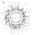
- the numeral 1 denotes a device for transferring pieces of filter rod 2 or of cigarette rod.
- the device 1 is preferably mounted on a cigarette making machine capable of operating simultaneously on two continuous filter rods advancing in parallel with each other.
- the device 1 transfers a pair of pieces 2 from a pickup station 7 to a release station 8.
- the pieces 2 of filter obtained by cutting continuous filter rods, are picked up and at the release station 8, the pieces 2 of filter rod are combined with respective pieces of cigarette rod.
- the transfer device 1 comprises a supporting drum 3 mounted rotatably about an axis of rotation A1.
- the drum 3 comprises at least one satellite element 4 having a respective gripper head 5 for picking up at least one piece 2 of filter rod.
- each gripper head 5 is equipped with a pair of seats 6 for simultaneously holding and transferring a pair of pieces 2.
- the drum 3 comprises a plurality of satellite elements 4 which are equispaced from each other along the periphery of the drum 3 itself.
- the satellite element 4 is driven in rotation by the drum 3, thus rotating about the first axis of rotation A1.
- the satellite element 4 also rotates about its own axis of rotation, referred to as second axis of rotation A2, parallel to the first axis of rotation A1.
- the transfer device 1 comprises movement means 9 for driving the satellite elements 4 and able to impart rotation to the satellite element 9 itself about the axis of rotation thereof, that is, about the second axis of rotation A2, as the drum 3 revolves about the first axis of rotation A1.
- each satellite element 2 is rotated about the first axis of rotation A1 by the action of the drum 3 and is also driven in rotation about its own axis of rotation, that is the second axis of rotation A2, by the action of the respective movement means 9.
- the movement means 9 comprise a transmission unit 19 and an actuator member 21 associated with the transmission unit 19.
- the transmission unit 19 comprises a sleeve 10 connected to the satellite element 4 and a shaft 11 movable along a direction parallel to its own main axis B, housed at least partly in the sleeve 10 and screwably engaged therewith by a helical profile 20. More specifically, the actuator member 21 is engaged with the shaft 11 of the transmission unit 19.
- the sleeve 10 has an internal chamber 13 which receives the shaft 11 in such a way as to surround at least the part of it which is screwably engaged therewith.
- the shaft 11 has on its outside surface a splined guide 14 defining the helical profile 20 of predetermined pitch P.
- the internal chamber 13 of the sleeve 10 also has a helical profile, which matches the helical profile of the splined guide 14 of the shaft 11.
- a plurality of spherical elements 15 are inserted in the splined guide 14 in such a way as to be interposed between the shaft 11 and the sleeve 10.
- the spherical elements 15, by rolling, allow the sleeve 10 and the shaft 11 to move relative to each other.
- the coupling between the shaft 11 and the sleeve 10 through the agency of the helical profile 20 allows the translational or linear motion of the shaft 11 to be converted into the rotational motion of the sleeve 10.
- the helical profile imparts helical motion composed of translational motion and rotational motion, so that translation is accomplished by the shaft 11 and rotation by the sleeve 10.
- the satellite element 4 and the sleeve 10 are coaxial parts, so that a rotation of the sleeve 10 corresponds to a rotation of the respective satellite element 4.
- the satellite element 4 is connected directly to the sleeve 10, without any transmission element being interposed between them.
- the transmission unit 19 comprises a bush 16 which is rotatably coupled to the sleeve 10.
- the bush 16 defines a first locking element by which the sleeve 10 is locked to the supporting drum 3.
- the bush 16 prevents the sleeve 10 from being translated relative to the selfsame shaft 11 along a direction parallel to the main axis B.
- the transmission unit 19 comprises a tube 17 which is slidably coupled to the shaft 11.
- the tube 17 defines a second locking element by which the shaft 11 is locked to the supporting drum 3.
- the tube 17 prevents it from rotating about the main axis B of the selfsame shaft 11.
- cylindrical shaft 11 and the sleeve 10 respectively define a threaded shaft and a lead nut of a recirculating ball screw assembly 18.
- the translational drive is imparted to the shaft 11 through the actuator member 21.
- the actuator member 21 comprises a cam 12, which rotates about the first axis of rotation A1 of the drum 3.
- the cam 12 has a profile for engaging with the shaft 11 with at least a first shaped stretch able to impart a translational movement to the selfsame shaft 11 in such a way that the gripper head 5 of the satellite element 4 is kept parallel to itself, according to an operating configuration, for each angular position of the drum 3 between the pickup station 7 and the release station 8.
- the respective seats 6 maintain their positions in respective horizontal planes.
- the transmission unit 19 allow gripper heads 5 of the satellite elements 4 to remain parallel to themselves, that is to say, do the respective seats 6 maintain their positions in respective horizontal planes, for each angular position of the drum 3, unlike the prior art, where the gripper heads 5 remained parallel to themselves in all the angular positions of the drum 3 during its rotation.
- each of the gripper heads 5 is rotated about its respective second axis of rotation A2 to return to its operating configuration.
- the cam 12 has a profile by which it engages the shaft 11 and which has at least a second stretch which is shaped to impart a translational movement such that from the release station 8 to the pickup station 7, the gripper head 5 of the satellite element 4 is returned to its operating configuration at the pickup station 7 by rotation about its respective second axis of rotation A2.
- the engagement profiles of the cam 12 are shaped stretches, each having a certain inclination to the vertical of the cam 12.
- the engagement profiles of the cam 12 are shaped in such a way as to cause the shaft 11 to advance in parallel to the main axis B in a first direction, indicated by the arrow F1, and in a second direction, indicated by the arrow F2, opposite to the first direction.
- the rotation of the satellite element 4, connected to the respective sleeve 10, is a function of the pitch P of the helical guide 14 formed on the cylindrical shaft 11.
- a quarter of the helicoid pitch corresponds to a rotation through approximately 90 sexagesimal degrees of the sleeve 10, and thus of the satellite element 4.
- the pitch of the helical guide is as large as possible in order to minimize positioning errors.
- a first advantage is the constructional simplicity of the transfer device 1 because the transmission unit 19 of each satellite element 4 is no longer housed inside the drum 3, as in the prior art, but is mounted peripherally of the drum 3, in alignment with the respective satellite element 4. This does away with the need for angle transmission devices and thus allows significantly higher precision.
- the transmission unit 19 such as the shaft 11 and the sleeve 10, are used in place, for example, of gears and appreciably reduce vibrations and noise.
Landscapes
- Manufacturing Of Cigar And Cigarette Tobacco (AREA)
- Cigarettes, Filters, And Manufacturing Of Filters (AREA)
Claims (9)
- Dispositif de transfert de bouts filtres ou de cigarette, comprenant un tambour (3) tournant autour d'un premier axe de rotation (A1), au moins un élément satellite (4) comprenant une tête de préhension respective (5) pour prélever au moins un bout filtre ou de cigarette (2) et qui est mobile entre un poste de prélèvement (7), où le bout (2) est prélevé, et un poste de libération (8), où le même bout (2) est libéré ; l'élément satellite (4) tournant autour d'un second axe de rotation (A2) parallèle au premier axe de rotation (A1) ; le dispositif de transfert (1) comprenant des moyens de déplacement (9) servant à entraîner l'élément satellite (4) et étant caractérisé en ce que les moyens de déplacement (9) comprennent une unité de transmission (19) comprenant un manchon (10) relié à l'élément satellite (4) et un arbre (11) mobile le long d'une direction parallèle à son propre axe (B), logé au moins en partie dans le manchon (10) et se mettant en prise par vissage par un profil hélicoïdal (20), les moyens de déplacement comprenant un organe d'actionnement (21) associé à l'unité de transmission (19) et se mettant en prise avec l'arbre (11) ; l'organe d'actionnement (21) provoquant la translation de l'arbre (11) le long d'une direction parallèle à l'axe principal (B) ; la translation, au moyen du profil hélicoïdal (20), provoquant à son tour la rotation autour du second axe de rotation (A2) du manchon (10) et de l'élément satellite respectif (4).
- Dispositif de transfert selon la revendication 1, caractérisé en ce que l'unité de transmission (19) comprend un premier élément de blocage (16) par lequel le manchon (10) est relié au tambour de support (3) ; le premier élément de blocage (16) étant accouplé de façon rotative au manchon (10).
- Dispositif de transfert selon les revendications 1 ou 2, caractérisé en ce que l'unité de transmission (19) comprend un second élément de blocage (17) par lequel l'arbre (11) est relié au tambour de support (3) ; l'arbre (11) étant accouplé de façon coulissante au second élément de blocage (17).
- Dispositif de transfert selon la revendication 3, caractérisé en ce que l'organe d'actionnement (21) comprend une came (12), pouvant pivoter autour du premier axe de rotation (A1) et ayant un profil pouvant se mettre en prise avec l'arbre (11) ayant au moins une première portion ayant une forme adaptée pour imprimer un mouvement de translation au même arbre (11) de sorte que la tête de préhension (5) de l'élément satellite (4) soit maintenue parallèle à elle-même, selon une configuration de fonctionnement, pour chaque position angulaire du tambour (3) entre le poste de prélèvement (7) et le poste de libération (8).
- Dispositif de transfert selon la revendication 4, caractérisé en ce que la came (12) possède un profil se pouvant se mettre en prise avec l'arbre (11) ayant au moins une seconde portion destinée à imprimer un mouvement de translation au même arbre (11) de sorte que du poste de libération (8) au poste de prélèvement (7), la tête de préhension (5) de l'élément satellite (4) revienne à sa configuration de fonctionnement au niveau du poste de prélèvement (7).
- Dispositif de transfert selon la revendication 5, caractérisé en ce que du poste de libération (8) au poste de prélèvement (7), la tête de préhension (5) de l'élément satellite (4) respectif tourne autour du second axe de rotation (A2).
- Dispositif de transfert selon l'une quelconque des revendications de 1 à 6, caractérisé en ce que l'arbre (11) possède sur sa surface externe un guide cannelé (14) définissant le profil hélicoïdal (20) de pas prédéfini (P) ; la rotation de l'élément satellite (4) étant fonction du pas (P) du guide (14) cannelé hélicoïdal.
- Dispositif de transfert selon la revendication 7, caractérisé en ce que la translation de l'arbre (11) le long de son axe principal (B) et le profil façonné de la came (12) dépendent du pas (P) du guide (14) cannelé hélicoïdal.
- Dispositif de transfert selon l'une quelconque des revendications de 1 à 8, caractérisé en ce que l'arbre (11) et le manchon (10) définissent respectivement un arbre fileté et un écrou fileté d'un assemblage par vis à recirculation de billes (18).
Priority Applications (1)
| Application Number | Priority Date | Filing Date | Title |
|---|---|---|---|
| PL13195936T PL2742811T3 (pl) | 2012-12-11 | 2013-12-05 | Urządzenie do transportu elementów wałka filtra lub papierosa |
Applications Claiming Priority (1)
| Application Number | Priority Date | Filing Date | Title |
|---|---|---|---|
| IT000664A ITBO20120664A1 (it) | 2012-12-11 | 2012-12-11 | Dispositivo di trasferimento di spezzoni di filtro o di sigaretta. |
Publications (2)
| Publication Number | Publication Date |
|---|---|
| EP2742811A1 EP2742811A1 (fr) | 2014-06-18 |
| EP2742811B1 true EP2742811B1 (fr) | 2015-08-12 |
Family
ID=47683815
Family Applications (1)
| Application Number | Title | Priority Date | Filing Date |
|---|---|---|---|
| EP13195936.3A Not-in-force EP2742811B1 (fr) | 2012-12-11 | 2013-12-05 | Dispositif de transfert de pièces de tige de filtre ou de cigarette |
Country Status (3)
| Country | Link |
|---|---|
| EP (1) | EP2742811B1 (fr) |
| IT (1) | ITBO20120664A1 (fr) |
| PL (1) | PL2742811T3 (fr) |
Family Cites Families (5)
| Publication number | Priority date | Publication date | Assignee | Title |
|---|---|---|---|---|
| IT1172096B (it) * | 1981-11-24 | 1987-06-18 | Gd Spa | Dispositivo per il trasverimento di spezzioni di sigarettada una macchina confezionatrice a doppio eaco di sigarettaad una macchina mettifiltro |
| ITBO20040046A1 (it) * | 2004-02-03 | 2004-05-03 | Gd Spa | Unita' combinata per la realizzazione di articoli da fumo |
| DE102004047266A1 (de) * | 2004-09-24 | 2006-04-06 | Hauni Maschinenbau Ag | Vorrichtung zur Übergabe stabförmiger Artikel |
| DE102009022024B4 (de) * | 2009-05-15 | 2011-06-16 | Hauni Maschinenbau Ag | Fördervorrichtung mit Unterdruckansaugung |
| ITBO20110158A1 (it) * | 2011-03-28 | 2012-09-29 | Gd Spa | Tamburo di trasferimento o di accompagnamento per spezzoni di filtro o di sigaretta con teste operative portate da bracci radiali. |
-
2012
- 2012-12-11 IT IT000664A patent/ITBO20120664A1/it unknown
-
2013
- 2013-12-05 EP EP13195936.3A patent/EP2742811B1/fr not_active Not-in-force
- 2013-12-05 PL PL13195936T patent/PL2742811T3/pl unknown
Also Published As
| Publication number | Publication date |
|---|---|
| ITBO20120664A1 (it) | 2014-06-12 |
| EP2742811A1 (fr) | 2014-06-18 |
| PL2742811T3 (pl) | 2015-12-31 |
Similar Documents
| Publication | Publication Date | Title |
|---|---|---|
| EP1905316B1 (fr) | Unité de découpage pour couper au moins une tige continue | |
| CN200995324Y (zh) | 活动块与弹簧的组装装置 | |
| CN107813046B (zh) | 用于支撑管加工机上的管的支撑装置及相关的管加工机 | |
| US4483351A (en) | Turnaround device for rod-like articles, in particular cigarettes | |
| US9089164B2 (en) | Transfer or feed drum, with radial-arm-mounted operating heads, for filter or cigarette portions | |
| US20130047803A1 (en) | Cutting machine | |
| US10196135B2 (en) | Device aircraft undercarriage leg including rack-and -pinion type means for controlling the orientation of the wheels of the undercarriage leg | |
| CN104818576A (zh) | 一种轨道可变的角导轮式复合材料三维编织成型机 | |
| CN108789447A (zh) | 静音针刺机器人及其恒弧长联动控制方法 | |
| EP2742811A1 (fr) | Dispositif de transfert de pièces de tige de filtre ou de cigarette | |
| CN105364191B (zh) | 分度调准装置及弧齿锥齿轮铣齿机 | |
| RU2649739C2 (ru) | Механизм опоры для изготавливающих стержни машин | |
| CN103949947A (zh) | 大型数控曲轴主轴颈外圆磨床 | |
| CN1933742A (zh) | 制造香烟的装置 | |
| CN108613000A (zh) | 一种拍摄范围广的监控装置 | |
| CN104400040A (zh) | 镗孔和端面加工头 | |
| CN109533909A (zh) | 90度斜摆轮分拣机 | |
| EP2440358B1 (fr) | Machine pour la production de roues dentees | |
| JP2005111545A (ja) | ばね製造機 | |
| US9682417B2 (en) | Bending device and spring manufacturing machine | |
| CN107750195B (zh) | 用于长形产品的剥皮机 | |
| CN208005062U (zh) | 钢材组立机 | |
| CN104889502A (zh) | 大型磨齿机砂轮架回转装置及其回转控制方法 | |
| CN101077514A (zh) | 用于回线形地弯曲一种连续的线材的装置 | |
| JP2011527943A5 (fr) |
Legal Events
| Date | Code | Title | Description |
|---|---|---|---|
| PUAI | Public reference made under article 153(3) epc to a published international application that has entered the european phase |
Free format text: ORIGINAL CODE: 0009012 |
|
| 17P | Request for examination filed |
Effective date: 20131205 |
|
| AK | Designated contracting states |
Kind code of ref document: A1 Designated state(s): AL AT BE BG CH CY CZ DE DK EE ES FI FR GB GR HR HU IE IS IT LI LT LU LV MC MK MT NL NO PL PT RO RS SE SI SK SM TR |
|
| AX | Request for extension of the european patent |
Extension state: BA ME |
|
| R17P | Request for examination filed (corrected) |
Effective date: 20140625 |
|
| RBV | Designated contracting states (corrected) |
Designated state(s): AL AT BE BG CH CY CZ DE DK EE ES FI FR GB GR HR HU IE IS IT LI LT LU LV MC MK MT NL NO PL PT RO RS SE SI SK SM TR |
|
| GRAP | Despatch of communication of intention to grant a patent |
Free format text: ORIGINAL CODE: EPIDOSNIGR1 |
|
| RIC1 | Information provided on ipc code assigned before grant |
Ipc: A24C 5/32 20060101AFI20150219BHEP |
|
| INTG | Intention to grant announced |
Effective date: 20150318 |
|
| GRAS | Grant fee paid |
Free format text: ORIGINAL CODE: EPIDOSNIGR3 |
|
| GRAA | (expected) grant |
Free format text: ORIGINAL CODE: 0009210 |
|
| AK | Designated contracting states |
Kind code of ref document: B1 Designated state(s): AL AT BE BG CH CY CZ DE DK EE ES FI FR GB GR HR HU IE IS IT LI LT LU LV MC MK MT NL NO PL PT RO RS SE SI SK SM TR |
|
| REG | Reference to a national code |
Ref country code: GB Ref legal event code: FG4D |
|
| REG | Reference to a national code |
Ref country code: CH Ref legal event code: EP |
|
| REG | Reference to a national code |
Ref country code: AT Ref legal event code: REF Ref document number: 741329 Country of ref document: AT Kind code of ref document: T Effective date: 20150815 |
|
| REG | Reference to a national code |
Ref country code: IE Ref legal event code: FG4D |
|
| REG | Reference to a national code |
Ref country code: DE Ref legal event code: R096 Ref document number: 602013002628 Country of ref document: DE |
|
| REG | Reference to a national code |
Ref country code: PL Ref legal event code: T3 |
|
| REG | Reference to a national code |
Ref country code: LT Ref legal event code: MG4D |
|
| REG | Reference to a national code |
Ref country code: AT Ref legal event code: MK05 Ref document number: 741329 Country of ref document: AT Kind code of ref document: T Effective date: 20150812 |
|
| REG | Reference to a national code |
Ref country code: NL Ref legal event code: MP Effective date: 20150812 |
|
| PG25 | Lapsed in a contracting state [announced via postgrant information from national office to epo] |
Ref country code: GR Free format text: LAPSE BECAUSE OF FAILURE TO SUBMIT A TRANSLATION OF THE DESCRIPTION OR TO PAY THE FEE WITHIN THE PRESCRIBED TIME-LIMIT Effective date: 20151113 Ref country code: LT Free format text: LAPSE BECAUSE OF FAILURE TO SUBMIT A TRANSLATION OF THE DESCRIPTION OR TO PAY THE FEE WITHIN THE PRESCRIBED TIME-LIMIT Effective date: 20150812 Ref country code: NO Free format text: LAPSE BECAUSE OF FAILURE TO SUBMIT A TRANSLATION OF THE DESCRIPTION OR TO PAY THE FEE WITHIN THE PRESCRIBED TIME-LIMIT Effective date: 20151112 Ref country code: FI Free format text: LAPSE BECAUSE OF FAILURE TO SUBMIT A TRANSLATION OF THE DESCRIPTION OR TO PAY THE FEE WITHIN THE PRESCRIBED TIME-LIMIT Effective date: 20150812 Ref country code: LV Free format text: LAPSE BECAUSE OF FAILURE TO SUBMIT A TRANSLATION OF THE DESCRIPTION OR TO PAY THE FEE WITHIN THE PRESCRIBED TIME-LIMIT Effective date: 20150812 |
|
| PG25 | Lapsed in a contracting state [announced via postgrant information from national office to epo] |
Ref country code: PT Free format text: LAPSE BECAUSE OF FAILURE TO SUBMIT A TRANSLATION OF THE DESCRIPTION OR TO PAY THE FEE WITHIN THE PRESCRIBED TIME-LIMIT Effective date: 20151214 Ref country code: SE Free format text: LAPSE BECAUSE OF FAILURE TO SUBMIT A TRANSLATION OF THE DESCRIPTION OR TO PAY THE FEE WITHIN THE PRESCRIBED TIME-LIMIT Effective date: 20150812 Ref country code: AT Free format text: LAPSE BECAUSE OF FAILURE TO SUBMIT A TRANSLATION OF THE DESCRIPTION OR TO PAY THE FEE WITHIN THE PRESCRIBED TIME-LIMIT Effective date: 20150812 Ref country code: HR Free format text: LAPSE BECAUSE OF FAILURE TO SUBMIT A TRANSLATION OF THE DESCRIPTION OR TO PAY THE FEE WITHIN THE PRESCRIBED TIME-LIMIT Effective date: 20150812 Ref country code: RS Free format text: LAPSE BECAUSE OF FAILURE TO SUBMIT A TRANSLATION OF THE DESCRIPTION OR TO PAY THE FEE WITHIN THE PRESCRIBED TIME-LIMIT Effective date: 20150812 Ref country code: ES Free format text: LAPSE BECAUSE OF FAILURE TO SUBMIT A TRANSLATION OF THE DESCRIPTION OR TO PAY THE FEE WITHIN THE PRESCRIBED TIME-LIMIT Effective date: 20150812 Ref country code: IS Free format text: LAPSE BECAUSE OF FAILURE TO SUBMIT A TRANSLATION OF THE DESCRIPTION OR TO PAY THE FEE WITHIN THE PRESCRIBED TIME-LIMIT Effective date: 20151212 |
|
| PG25 | Lapsed in a contracting state [announced via postgrant information from national office to epo] |
Ref country code: NL Free format text: LAPSE BECAUSE OF FAILURE TO SUBMIT A TRANSLATION OF THE DESCRIPTION OR TO PAY THE FEE WITHIN THE PRESCRIBED TIME-LIMIT Effective date: 20150812 |
|
| PG25 | Lapsed in a contracting state [announced via postgrant information from national office to epo] |
Ref country code: IT Free format text: LAPSE BECAUSE OF FAILURE TO SUBMIT A TRANSLATION OF THE DESCRIPTION OR TO PAY THE FEE WITHIN THE PRESCRIBED TIME-LIMIT Effective date: 20150812 Ref country code: EE Free format text: LAPSE BECAUSE OF FAILURE TO SUBMIT A TRANSLATION OF THE DESCRIPTION OR TO PAY THE FEE WITHIN THE PRESCRIBED TIME-LIMIT Effective date: 20150812 Ref country code: DK Free format text: LAPSE BECAUSE OF FAILURE TO SUBMIT A TRANSLATION OF THE DESCRIPTION OR TO PAY THE FEE WITHIN THE PRESCRIBED TIME-LIMIT Effective date: 20150812 Ref country code: CZ Free format text: LAPSE BECAUSE OF FAILURE TO SUBMIT A TRANSLATION OF THE DESCRIPTION OR TO PAY THE FEE WITHIN THE PRESCRIBED TIME-LIMIT Effective date: 20150812 Ref country code: SK Free format text: LAPSE BECAUSE OF FAILURE TO SUBMIT A TRANSLATION OF THE DESCRIPTION OR TO PAY THE FEE WITHIN THE PRESCRIBED TIME-LIMIT Effective date: 20150812 |
|
| REG | Reference to a national code |
Ref country code: DE Ref legal event code: R097 Ref document number: 602013002628 Country of ref document: DE |
|
| PG25 | Lapsed in a contracting state [announced via postgrant information from national office to epo] |
Ref country code: RO Free format text: LAPSE BECAUSE OF FAILURE TO SUBMIT A TRANSLATION OF THE DESCRIPTION OR TO PAY THE FEE WITHIN THE PRESCRIBED TIME-LIMIT Effective date: 20150812 Ref country code: BE Free format text: LAPSE BECAUSE OF NON-PAYMENT OF DUE FEES Effective date: 20151231 |
|
| PLBE | No opposition filed within time limit |
Free format text: ORIGINAL CODE: 0009261 |
|
| STAA | Information on the status of an ep patent application or granted ep patent |
Free format text: STATUS: NO OPPOSITION FILED WITHIN TIME LIMIT |
|
| 26N | No opposition filed |
Effective date: 20160513 |
|
| PG25 | Lapsed in a contracting state [announced via postgrant information from national office to epo] |
Ref country code: MC Free format text: LAPSE BECAUSE OF FAILURE TO SUBMIT A TRANSLATION OF THE DESCRIPTION OR TO PAY THE FEE WITHIN THE PRESCRIBED TIME-LIMIT Effective date: 20150812 Ref country code: LU Free format text: LAPSE BECAUSE OF FAILURE TO SUBMIT A TRANSLATION OF THE DESCRIPTION OR TO PAY THE FEE WITHIN THE PRESCRIBED TIME-LIMIT Effective date: 20151205 |
|
| PG25 | Lapsed in a contracting state [announced via postgrant information from national office to epo] |
Ref country code: SI Free format text: LAPSE BECAUSE OF FAILURE TO SUBMIT A TRANSLATION OF THE DESCRIPTION OR TO PAY THE FEE WITHIN THE PRESCRIBED TIME-LIMIT Effective date: 20150812 |
|
| REG | Reference to a national code |
Ref country code: IE Ref legal event code: MM4A |
|
| REG | Reference to a national code |
Ref country code: FR Ref legal event code: ST Effective date: 20160831 |
|
| PG25 | Lapsed in a contracting state [announced via postgrant information from national office to epo] |
Ref country code: IE Free format text: LAPSE BECAUSE OF NON-PAYMENT OF DUE FEES Effective date: 20151205 |
|
| PG25 | Lapsed in a contracting state [announced via postgrant information from national office to epo] |
Ref country code: FR Free format text: LAPSE BECAUSE OF NON-PAYMENT OF DUE FEES Effective date: 20151231 |
|
| PG25 | Lapsed in a contracting state [announced via postgrant information from national office to epo] |
Ref country code: BE Free format text: LAPSE BECAUSE OF FAILURE TO SUBMIT A TRANSLATION OF THE DESCRIPTION OR TO PAY THE FEE WITHIN THE PRESCRIBED TIME-LIMIT Effective date: 20150812 |
|
| PG25 | Lapsed in a contracting state [announced via postgrant information from national office to epo] |
Ref country code: HU Free format text: LAPSE BECAUSE OF FAILURE TO SUBMIT A TRANSLATION OF THE DESCRIPTION OR TO PAY THE FEE WITHIN THE PRESCRIBED TIME-LIMIT; INVALID AB INITIO Effective date: 20131205 Ref country code: BG Free format text: LAPSE BECAUSE OF FAILURE TO SUBMIT A TRANSLATION OF THE DESCRIPTION OR TO PAY THE FEE WITHIN THE PRESCRIBED TIME-LIMIT Effective date: 20150812 |
|
| PG25 | Lapsed in a contracting state [announced via postgrant information from national office to epo] |
Ref country code: CY Free format text: LAPSE BECAUSE OF FAILURE TO SUBMIT A TRANSLATION OF THE DESCRIPTION OR TO PAY THE FEE WITHIN THE PRESCRIBED TIME-LIMIT Effective date: 20150812 |
|
| REG | Reference to a national code |
Ref country code: CH Ref legal event code: PL |
|
| PG25 | Lapsed in a contracting state [announced via postgrant information from national office to epo] |
Ref country code: MT Free format text: LAPSE BECAUSE OF FAILURE TO SUBMIT A TRANSLATION OF THE DESCRIPTION OR TO PAY THE FEE WITHIN THE PRESCRIBED TIME-LIMIT Effective date: 20150812 |
|
| PG25 | Lapsed in a contracting state [announced via postgrant information from national office to epo] |
Ref country code: CH Free format text: LAPSE BECAUSE OF NON-PAYMENT OF DUE FEES Effective date: 20161231 Ref country code: LI Free format text: LAPSE BECAUSE OF NON-PAYMENT OF DUE FEES Effective date: 20161231 |
|
| PG25 | Lapsed in a contracting state [announced via postgrant information from national office to epo] |
Ref country code: SM Free format text: LAPSE BECAUSE OF FAILURE TO SUBMIT A TRANSLATION OF THE DESCRIPTION OR TO PAY THE FEE WITHIN THE PRESCRIBED TIME-LIMIT Effective date: 20150812 |
|
| PG25 | Lapsed in a contracting state [announced via postgrant information from national office to epo] |
Ref country code: MK Free format text: LAPSE BECAUSE OF FAILURE TO SUBMIT A TRANSLATION OF THE DESCRIPTION OR TO PAY THE FEE WITHIN THE PRESCRIBED TIME-LIMIT Effective date: 20150812 |
|
| GBPC | Gb: european patent ceased through non-payment of renewal fee |
Effective date: 20171205 |
|
| PG25 | Lapsed in a contracting state [announced via postgrant information from national office to epo] |
Ref country code: TR Free format text: LAPSE BECAUSE OF FAILURE TO SUBMIT A TRANSLATION OF THE DESCRIPTION OR TO PAY THE FEE WITHIN THE PRESCRIBED TIME-LIMIT Effective date: 20150812 Ref country code: AL Free format text: LAPSE BECAUSE OF FAILURE TO SUBMIT A TRANSLATION OF THE DESCRIPTION OR TO PAY THE FEE WITHIN THE PRESCRIBED TIME-LIMIT Effective date: 20150812 |
|
| PG25 | Lapsed in a contracting state [announced via postgrant information from national office to epo] |
Ref country code: GB Free format text: LAPSE BECAUSE OF NON-PAYMENT OF DUE FEES Effective date: 20171205 |
|
| PGFP | Annual fee paid to national office [announced via postgrant information from national office to epo] |
Ref country code: PL Payment date: 20181122 Year of fee payment: 6 |
|
| PGFP | Annual fee paid to national office [announced via postgrant information from national office to epo] |
Ref country code: DE Payment date: 20181231 Year of fee payment: 6 |
|
| REG | Reference to a national code |
Ref country code: DE Ref legal event code: R119 Ref document number: 602013002628 Country of ref document: DE |
|
| PG25 | Lapsed in a contracting state [announced via postgrant information from national office to epo] |
Ref country code: DE Free format text: LAPSE BECAUSE OF NON-PAYMENT OF DUE FEES Effective date: 20200701 |
|
| PG25 | Lapsed in a contracting state [announced via postgrant information from national office to epo] |
Ref country code: PL Free format text: LAPSE BECAUSE OF NON-PAYMENT OF DUE FEES Effective date: 20191205 |