EP2742598B1 - Antenna to transceiver mapping of a multimode wireless device - Google Patents
Antenna to transceiver mapping of a multimode wireless device Download PDFInfo
- Publication number
- EP2742598B1 EP2742598B1 EP12745962.6A EP12745962A EP2742598B1 EP 2742598 B1 EP2742598 B1 EP 2742598B1 EP 12745962 A EP12745962 A EP 12745962A EP 2742598 B1 EP2742598 B1 EP 2742598B1
- Authority
- EP
- European Patent Office
- Prior art keywords
- antennas
- antenna
- transceivers
- transceiver
- mapping
- Prior art date
- Legal status (The legal status is an assumption and is not a legal conclusion. Google has not performed a legal analysis and makes no representation as to the accuracy of the status listed.)
- Active
Links
- 238000013507 mapping Methods 0.000 title claims description 56
- 238000005259 measurement Methods 0.000 claims description 66
- 238000000034 method Methods 0.000 claims description 57
- 238000005516 engineering process Methods 0.000 claims description 46
- 238000004891 communication Methods 0.000 claims description 42
- 230000005540 biological transmission Effects 0.000 description 14
- 230000015654 memory Effects 0.000 description 12
- 230000003936 working memory Effects 0.000 description 8
- 230000001413 cellular effect Effects 0.000 description 7
- 230000008859 change Effects 0.000 description 5
- 230000010267 cellular communication Effects 0.000 description 4
- 230000006870 function Effects 0.000 description 4
- 230000003287 optical effect Effects 0.000 description 4
- 230000008569 process Effects 0.000 description 4
- 238000009434 installation Methods 0.000 description 3
- 230000004044 response Effects 0.000 description 3
- 238000004458 analytical method Methods 0.000 description 2
- 238000010586 diagram Methods 0.000 description 2
- 230000007774 longterm Effects 0.000 description 2
- 238000012913 prioritisation Methods 0.000 description 2
- 238000012545 processing Methods 0.000 description 2
- 230000001133 acceleration Effects 0.000 description 1
- 230000006835 compression Effects 0.000 description 1
- 238000007906 compression Methods 0.000 description 1
- 238000004590 computer program Methods 0.000 description 1
- 238000010276 construction Methods 0.000 description 1
- 230000008878 coupling Effects 0.000 description 1
- 238000010168 coupling process Methods 0.000 description 1
- 238000005859 coupling reaction Methods 0.000 description 1
- 238000013500 data storage Methods 0.000 description 1
- 230000006837 decompression Effects 0.000 description 1
- 230000001419 dependent effect Effects 0.000 description 1
- 238000013461 design Methods 0.000 description 1
- 230000007613 environmental effect Effects 0.000 description 1
- 230000006872 improvement Effects 0.000 description 1
- 238000007726 management method Methods 0.000 description 1
- 238000004519 manufacturing process Methods 0.000 description 1
- 238000012986 modification Methods 0.000 description 1
- 230000004048 modification Effects 0.000 description 1
- 230000000737 periodic effect Effects 0.000 description 1
- 230000001360 synchronised effect Effects 0.000 description 1
Images


Classifications
-
- H—ELECTRICITY
- H04—ELECTRIC COMMUNICATION TECHNIQUE
- H04B—TRANSMISSION
- H04B1/00—Details of transmission systems, not covered by a single one of groups H04B3/00 - H04B13/00; Details of transmission systems not characterised by the medium used for transmission
- H04B1/38—Transceivers, i.e. devices in which transmitter and receiver form a structural unit and in which at least one part is used for functions of transmitting and receiving
- H04B1/40—Circuits
- H04B1/44—Transmit/receive switching
-
- H—ELECTRICITY
- H04—ELECTRIC COMMUNICATION TECHNIQUE
- H04B—TRANSMISSION
- H04B7/00—Radio transmission systems, i.e. using radiation field
- H04B7/02—Diversity systems; Multi-antenna system, i.e. transmission or reception using multiple antennas
- H04B7/04—Diversity systems; Multi-antenna system, i.e. transmission or reception using multiple antennas using two or more spaced independent antennas
- H04B7/0404—Diversity systems; Multi-antenna system, i.e. transmission or reception using multiple antennas using two or more spaced independent antennas the mobile station comprising multiple antennas, e.g. to provide uplink diversity
-
- H—ELECTRICITY
- H01—ELECTRIC ELEMENTS
- H01Q—ANTENNAS, i.e. RADIO AERIALS
- H01Q1/00—Details of, or arrangements associated with, antennas
- H01Q1/12—Supports; Mounting means
- H01Q1/22—Supports; Mounting means by structural association with other equipment or articles
- H01Q1/24—Supports; Mounting means by structural association with other equipment or articles with receiving set
- H01Q1/241—Supports; Mounting means by structural association with other equipment or articles with receiving set used in mobile communications, e.g. GSM
- H01Q1/242—Supports; Mounting means by structural association with other equipment or articles with receiving set used in mobile communications, e.g. GSM specially adapted for hand-held use
-
- H—ELECTRICITY
- H01—ELECTRIC ELEMENTS
- H01Q—ANTENNAS, i.e. RADIO AERIALS
- H01Q21/00—Antenna arrays or systems
- H01Q21/28—Combinations of substantially independent non-interacting antenna units or systems
-
- H—ELECTRICITY
- H04—ELECTRIC COMMUNICATION TECHNIQUE
- H04W—WIRELESS COMMUNICATION NETWORKS
- H04W52/00—Power management, e.g. TPC [Transmission Power Control], power saving or power classes
- H04W52/02—Power saving arrangements
- H04W52/0209—Power saving arrangements in terminal devices
- H04W52/0225—Power saving arrangements in terminal devices using monitoring of external events, e.g. the presence of a signal
- H04W52/0245—Power saving arrangements in terminal devices using monitoring of external events, e.g. the presence of a signal according to signal strength
-
- H—ELECTRICITY
- H04—ELECTRIC COMMUNICATION TECHNIQUE
- H04W—WIRELESS COMMUNICATION NETWORKS
- H04W72/00—Local resource management
- H04W72/04—Wireless resource allocation
- H04W72/044—Wireless resource allocation based on the type of the allocated resource
- H04W72/046—Wireless resource allocation based on the type of the allocated resource the resource being in the space domain, e.g. beams
-
- H—ELECTRICITY
- H04—ELECTRIC COMMUNICATION TECHNIQUE
- H04W—WIRELESS COMMUNICATION NETWORKS
- H04W72/00—Local resource management
- H04W72/50—Allocation or scheduling criteria for wireless resources
- H04W72/54—Allocation or scheduling criteria for wireless resources based on quality criteria
- H04W72/542—Allocation or scheduling criteria for wireless resources based on quality criteria using measured or perceived quality
-
- H—ELECTRICITY
- H04—ELECTRIC COMMUNICATION TECHNIQUE
- H04W—WIRELESS COMMUNICATION NETWORKS
- H04W88/00—Devices specially adapted for wireless communication networks, e.g. terminals, base stations or access point devices
- H04W88/02—Terminal devices
- H04W88/06—Terminal devices adapted for operation in multiple networks or having at least two operational modes, e.g. multi-mode terminals
-
- H—ELECTRICITY
- H04—ELECTRIC COMMUNICATION TECHNIQUE
- H04B—TRANSMISSION
- H04B7/00—Radio transmission systems, i.e. using radiation field
- H04B7/02—Diversity systems; Multi-antenna system, i.e. transmission or reception using multiple antennas
- H04B7/04—Diversity systems; Multi-antenna system, i.e. transmission or reception using multiple antennas using two or more spaced independent antennas
- H04B7/06—Diversity systems; Multi-antenna system, i.e. transmission or reception using multiple antennas using two or more spaced independent antennas at the transmitting station
- H04B7/0602—Diversity systems; Multi-antenna system, i.e. transmission or reception using multiple antennas using two or more spaced independent antennas at the transmitting station using antenna switching
-
- H—ELECTRICITY
- H04—ELECTRIC COMMUNICATION TECHNIQUE
- H04B—TRANSMISSION
- H04B7/00—Radio transmission systems, i.e. using radiation field
- H04B7/02—Diversity systems; Multi-antenna system, i.e. transmission or reception using multiple antennas
- H04B7/04—Diversity systems; Multi-antenna system, i.e. transmission or reception using multiple antennas using two or more spaced independent antennas
- H04B7/08—Diversity systems; Multi-antenna system, i.e. transmission or reception using multiple antennas using two or more spaced independent antennas at the receiving station
- H04B7/0802—Diversity systems; Multi-antenna system, i.e. transmission or reception using multiple antennas using two or more spaced independent antennas at the receiving station using antenna selection
-
- H—ELECTRICITY
- H04—ELECTRIC COMMUNICATION TECHNIQUE
- H04W—WIRELESS COMMUNICATION NETWORKS
- H04W48/00—Access restriction; Network selection; Access point selection
- H04W48/18—Selecting a network or a communication service
-
- Y—GENERAL TAGGING OF NEW TECHNOLOGICAL DEVELOPMENTS; GENERAL TAGGING OF CROSS-SECTIONAL TECHNOLOGIES SPANNING OVER SEVERAL SECTIONS OF THE IPC; TECHNICAL SUBJECTS COVERED BY FORMER USPC CROSS-REFERENCE ART COLLECTIONS [XRACs] AND DIGESTS
- Y02—TECHNOLOGIES OR APPLICATIONS FOR MITIGATION OR ADAPTATION AGAINST CLIMATE CHANGE
- Y02D—CLIMATE CHANGE MITIGATION TECHNOLOGIES IN INFORMATION AND COMMUNICATION TECHNOLOGIES [ICT], I.E. INFORMATION AND COMMUNICATION TECHNOLOGIES AIMING AT THE REDUCTION OF THEIR OWN ENERGY USE
- Y02D30/00—Reducing energy consumption in communication networks
- Y02D30/70—Reducing energy consumption in communication networks in wireless communication networks
Definitions
- Devices capable of wireless communication may have multiple antennas.
- a consumer cellular phone may have one or more antennas associated with cellular communication and local wireless protocols.
- Each of these antennas may be coupled with a transceiver that transmits and/or receives using a particular radio technology.
- certain antennas may be less effective at communication than other antennas. Arrangements for determining which antennas are likely to be most effective at receiving and/or transmitting wireless signals are desired and may be useful to conserve power of wireless devices.
- operation of multiple radios may be controlled using a database of interference-related information, which may be indicative of interference between different radios operating concurrently.
- an entity may obtain planned operating states of multiple radios in an upcoming interval. The entity may determine the performance of one or more radios based on the planned operating states of the radios and the database, which may store information on performance versus operating states for different combinations of radios.
- the document US 2008/085736 A1 refers to a tablet type computer for radio communication with other radio devices using two or more antennas in which, when sending radio waves, a radio communication control unit switches the antennas so that sending of radio signals is made using the antenna disposed at a position farthest from the operator or disposed at a position where the possibility of a part of the operator body coming in touch with the antenna is the lowest.
- the document US 2008/267108 A1 refers to multiuser scheduling in a multiple-input multiple-output (MIMO) communication system.
- Multiuser scheduling is performed based on an antenna selection and signal quality feedback, such as signal-to-interference-plus-noise ratio (SINR) feedback, from respective users.
- SINR signal-to-interference-plus-noise ratio
- independent information streams can be transmitted from respective transmit antennas to respective users with the highest signal quality.
- Receive antenna selection can also be employed to allow respective users to select a single receive antenna on which information is to be received.
- EP 1 533 918 A2 describing a receiver which selects optimum antennas while minimizing the number of times of antenna switching is provided.
- three or more antennas receive radio waves, and output respective transmission signals.
- Two antennas are selected by a selecting unit, and the transmission signals output from the two antennas are demodulated individually and combined.
- the quality levels of the transmission signals output from the antennas are detected by a detecting unit.
- a control unit selects two antennas from among the three or more antennas based on the quality levels of the transmission signals output from the antennas. Consequently, when the quality level of the transmission signal output from a selected antenna falls below the predetermined level, optimum antennas can be selected based on the detected quality levels of the transmission signals with an improvement to the reception quality.
- the method can include detecting whether the mobile station is being held properly. In response to detecting that the mobile station is not being held properly, an indicator can be presented via a user interface to indicate to a user that the mobile station is being held improperly. The method also can include, responsive to detecting that the mobile station is being held properly, generating an indicator via the user interface that indicates to the user that the mobile station is being held properly.
- Many devices such as mobile devices, that are capable of wireless communication have multiple antennas. Such devices may have multiple transceivers, with each transceiver coupled with, typically, one or two antennas.
- a mobile device such as a cellular phone
- a transceiver that communicates with a cellular network, using a cellular communication radio technology, such as CDMA.
- This CDMA transceiver may be coupled with two antennas to allow for diversity reception, when necessary.
- This same mobile device may have multiple other transceivers, such as a transceiver for Bluetooth and a transceiver for WiFi radio technologies. If each of these transceivers is connected with two dedicated antennas, the total number of antennas on the mobile device is, at a minimum, six.
- Other mobile devices may contain even greater numbers of transceivers and, thus, greater numbers of antennas. As the number of transceivers on a mobile device increases, the number of antennas may similarly increase if antennas are dedicated to a particular transceiver.
- an antenna may be configured to be alternatively mapped to multiple transceivers.
- the mapping may include selectively connecting, either physically or functionally, a transceiver of a plurality of transceivers to a given antenna.
- the transceiver can be mapped to another antenna selected from a set (e.g., plurality) of antennas that may be used regardless of the radio technology of the transceiver.
- the antennas may be radio technology-independent.
- an antenna that is currently used for cellular communication may, at some other point in time, be used in conjunction with a different radio technology, such as WiFi, that relies on a different protocol and/or frequency.
- any transceiver used for wireless communications in a device may be selectively connected to and used with a certain antenna or a certain group of antennas used in that device.
- any transceiver used for wireless communications in a device may be selectively connected to and used with any antenna implemented in that device.
- a set of antennas may permit antennas that are likely to serve as an effective electromagnetic transducer to be used.
- a user's body, or some other form of physical entity, in contact with an antenna may degrade the antenna's ability to function as an effective electromagnetic transducer due to the user's body obstructing transmission and/or reception of signals and/or the user's body altering the electromagnetic characteristics of the antenna.
- an antenna is located, at least partially, on the mobile device's external surface, while the user is holding the device, the user's hand may contact the antenna. Such contact may degrade that antenna's ability to function as an effective electromagnetic transducer.
- receiving and/or transmitting (referred to generally as “communicating") using that antenna may result in: 1) a lower signal-to-noise ratio (SNR); 2) diversity reception being desired; and/or 3) increased power consumption (such as due to using diversity reception or having to transmit at a higher power level).
- SNR signal-to-noise ratio
- communication using one or more antennas not in contact (or in less contact) with a user or some other physical entity may result in improved communication with a remote wireless network.
- the device may determine which antenna (or antennas) to use. For example, the device may select from one or more idle antennas (e.g., that are not being used for communication by a transducer) or may reassign antennas currently in use. Since certain of the antennas that are available to use may currently be idle, it may not be possible to use SNR measurements to select which of these antennas to use because the antennas are not currently mapped to a transceiver or being used for communication. Rather than using SNR measurements to select an antenna to use, touch sense measurements, collected by one or more touch sensors, may be used to determine which antennas are likely to serve as an effective electromagnetic transducer.
- Each antenna may be monitored by one or more touch sensors.
- Each touch sensor may be able to determine whether a physical entity, such as a user or other external object, is in contact with a corresponding antenna. If a physical entity is determined to be in contact with an antenna, the corresponding touch sensor may provide an indication of how much contact is present. For example, a touch sensor may provide a score, such as on a scale of 1-10, of how much contact is present between the antenna and the physical entity.
- the device may give preference to antennas that have the least contact with physical entities. As such, if the device determines to map a transceiver to a different antenna, an antenna that has the least contact with a physical entity may be selected as being more likely to serve as an effective electromagnetic transducer than the antennas in contact with the physical entity.
- Such mapping of antennas with transceivers of different radio technologies may result in lowered electrical current usage and, thus, lower power consumption.
- the transceiver when a transceiver is not in use (e.g., it has not transmitted or received for a certain period of time or has been deactivated by a user), the transceiver may be powered down and disconnected from all antennas.
- a single antenna that can serve as a more effective electromagnetic transducer may be used instead.
- Using a more effective antenna(s) may result in less power being used by the associated transceivers. In a mobile device, this may translate to extended battery life and/or a lower ampere-hour.
- FIG. 1 illustrates an embodiment of a system 100 having multiple antennas configured to be mapped to multiple transceivers.
- System 100 may include: antennas 110, transceivers 120, selector circuit 130, and processor 140.
- System 100 may be present in a device that communicates wirelessly.
- System 100 may be present in a mobile device, such as a cellular phone.
- System 100 may also be present in other forms of mobile devices, such as: tablet computers, laptop computers, and gaming devices. Other devices may also contain system 100.
- antennas 110 may represent all antennas present on a device, or a portion of the antennas present on the device.
- Antennas 110 may include two or more antennas.
- Antennas 110 may be coupled with selector circuit 130.
- Each antenna of antennas 110 may be a wideband antenna configured to communicate (e.g., transmit and/or receive radio signals) in accordance with different radio technologies.
- each antenna of antennas 110 may be configured to serve as an effective electromagnetic transducer for radio technologies and/or multiple different frequencies.
- antennas 110 are identical.
- various antennas of antennas 110 may have different characteristics such that some antennas are more effective at serving as a transducer for particular frequencies or wireless protocols.
- antenna 110-1 may be an antenna that can be effectively used as an electromagnetic transducer at a variety of frequencies but is more effective when used for a particular range of frequencies.
- antenna 110-2 may be an antenna that can be effectively used as an electromagnetic transducer at a variety of frequencies but is more effective when used for a particular range of frequencies.
- the range of frequencies for antenna 110-2 may be different from the range of frequencies for antenna 110-1.
- antenna 110-1 may be used as a default antenna for a first transceiver that communicates using a frequency within the range of frequencies of antenna 110-1 and antenna 110-2 may be used as a default antenna for a second transceiver that communicates using a frequency within the range of frequencies of antenna 110-2.
- antenna 110-2 may be used with the first transceiver, and antenna 110-1 may be used with the second transceiver in some embodiments, even if the transceivers use different radio technologies.
- Selector circuit 130 may be coupled with antennas 110 and transceivers 120. Selector circuit 130 may be configured to map any transceiver of transceivers 120 with any antenna of antennas 110. Selector circuit 130 may be a separate circuit, may be part of processor 140, or may be part of some other processor. Mapping may refer to associating a particular transceiver with a particular antenna. For example, when selector circuit 130 has "mapped" a transceiver to an antenna, radio signals received via the antenna are provided to the input of the transceiver, and the output of the transceiver is provided to the antenna. Selector circuit 130 may map transceivers 120 with antennas 110 via soft switching.
- selector circuit 130 may route data to and from various antenna/transceiver combinations by altering the memory addresses of selector circuit 130.
- Information received via antenna 110-1 may be written to a memory address linked with a particular transceiver. If antenna 110-1 is mapped to a different transceiver, a different memory address may be used.
- Selector circuit 130 may be configured to map multiple antennas of antennas 110 to a single transceiver of transceivers 120. Such an arrangement may allow for diversity communication by allowing a single transceiver to use two (or more) antennas. Besides soft switching, in some embodiments mapping may involve selector circuit 130 physically coupling one or more transceivers to one or more antennas.
- Processor 140 may determine which antenna or antennas should be mapped with which transceivers. Processor 140 may determine whether a transceiver should use a single antenna or diversity. Processor 140 may be in communication with selector circuit 130. Processor 140 may control the mapping of antennas 110 to transceivers 120 via selector circuit 130.
- Transceivers 120 may include two or more transceivers. Each transceiver of transceivers 120 may communicate using a different radio technology. In some embodiments, multiple transceivers that use the same radio technology may be present. Transceivers 120 may represent all or a portion of the transceivers present on a device.. Each of the transceivers 120 may implement receive functionality and/or transmit functionality. Thus, use of the term transceiver herein does not imply or require that the transceiver be able to both transmit and receive messages or communications. Each of the transceivers 120 may be used to only receive information, to only transmit information, or to both receive and transmit information. For example, embodiments described herein including transceivers may be implemented using solely receivers. Alternatively, such embodiments may be implemented using only transmitters, a combination of separate receivers and transmitters, or using elements that perform both reception and transmission.
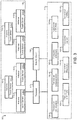
- FIG. 2 illustrates an embodiment of a system 200 for a mobile device having multiple antennas configured to be mapped to multiple transceivers.
- System 200 may represent some embodiments of system 100.
- System 200 includes: antennas 110, transceivers 120, selector circuit 130, and processor 140.
- System 200 may be present in a mobile device, such as a cellular phone.
- a mobile device may be capable of communication via multiple radio technologies, including: CDMA, LTE, Bluetooth, WLAN (e.g., 802.11x), and WiMax.
- System 200 is illustrated as having six antennas. All antennas of the mobile device that includes system 100 may be coupled with selector circuit 130. In some embodiments, some antennas of the mobile device may not be connected with selector circuit 130.
- Each antenna of antennas 110 may be a wideband antenna configured to communicate using multiple radio technologies. For example, each antenna of antennas 110 may be effective at communicating using each radio technology of transceivers 120. In some embodiments, some or all of antennas 110 may be configured to be most effective for a particular radio technology and/or range of frequencies. For example, antenna 110-3 may be configured to be most effective for Bluetooth-based communication, but may also be sufficiently effective for use with other radio technologies and/or frequencies.
- Antenna 110-4 may be most effective for WiMax-based communication, but may also be effective for other radio technologies and/or frequencies.
- Each of antennas 110 may be located within, partially within, or external to the mobile device that includes system 200.
- one or more antennas of antennas 110 may be internal to the mobile device, one or more antennas may partially extrude from the mobile device (e.g., the antenna is on one or more external surfaces of the mobile device), and one or more antennas may extrude from the mobile device (e.g., the antenna extends from the body of the mobile device).
- Selector circuit 130 may be coupled with antennas 110 and transceivers 120. Selector circuit 130 may be configured to map any antenna of antennas 110 with any transceiver of transceivers 120. In some embodiments, certain antenna/transceiver mappings may be impermissible. For example, transceiver 120-3 may not be permitted to be mapped to antenna 110-6. Such a mapping may be impermissible if a particular antenna is considered ineffective for use with a particular radio technology and/or range of frequencies. Selector circuit 130 may be a separate circuit, may be part of processor 140, or may be part of some other processor. Selector circuit 130 may map transceivers 120 with antennas 110 via soft switching as detailed in relation to system 100. Selector circuit 130 of system 200 may also permit diversity communication by mapping a transceiver with two or more antennas of antennas 110.
- each transceiver of transceivers 120 to selector circuit 130 is not illustrated. It should be understood that a connection between each transceiver of transceivers 120 and selector circuit 130 may be present. Similarly, the routing from each antenna of antennas 110 to selector circuit 130 is not illustrated. It should be understood that a connection between each antenna of antenna 110 and selector circuit 130 may be present.
- Processor 140 may determine which antenna or antennas should be mapped to which transceivers.
- Processor 140 may be in communication with selector circuit 130 and each transceiver of transceivers 120. Communication with transceivers 120 may permit processor 140 to determine when diversity and/or changing the mapping of an antenna of antennas 110 to a transceiver of transceivers 120 is needed.
- Transceivers 120 are illustrated as including eight transceivers. It should be understood that more or fewer transceivers may be present. Each transceiver of transceivers 120 may communicate using a different radio technology.
- transceiver 120-3 is for TD-SCDMA (Time Division Synchronous Code Division Multiple Access)
- transceiver 120-4 is for CDMA/EVDO (Code Division Multiple Access/Evolution Data Optimized)
- transceiver 120-5 is for WCDMA (Wideband Code Division Multiple Access)
- transceiver 120-6 is for LTE-FDD (Long Term Evolution Frequency Division Duplex)
- transceiver 120-7 is for LTE-TDD (Long Term Evolution Time Division Duplex)
- transceiver 120-8 is for Bluetooth
- transceiver 120-9 is for WLAN (Wireless Local Area Network) (e.g., an 802.11x wireless network)
- transceiver 120-10 is for WiMax (Worldwide Interoperability for Microwave Access). It should be
- all transceivers may not be used at the same time. For example, if a mobile device is communicating using CDMA, LTE transceivers may not be active at the same time.
- the number of antennas present in system 200 may be reduced because antennas are shared by transceivers using different radio technologies. As illustrated in system 200 of FIG. 2 , six antennas are present in antennas 110. Therefore, only six or fewer of transceivers 120 may be communicating using a dedicated antenna at a given time. Accordingly, one or more transceivers of transceivers 120 may be in a powered-down mode when not mapped to an antenna of antennas 110. A transceiver in a powered-down mode may use less current/power than when in a powered-up mode.
- Reducing the number of antennas present in system 200 may save space within the mobile device and/or may decrease manufacturing/material costs. If a transceiver of transceivers 120 is using diversity communication, and thus is using two or more antennas, even fewer other transceivers may be active because of the limited number of antennas 110. In some embodiments, if additional antennas are needed, a transceiver using diversity communication may be re-mapped to only one antenna to free an antenna to be mapped to another transceiver.
- FIG. 3 illustrates an embodiment of a system for a mobile device having multiple antennas configured to be mapped to multiple transceivers at least partially based on indications from touch sensors.
- System 300 may represent some embodiments of system 100 and system 200 of FIGS. 1 and 2 , respectively.
- System 300 includes: antennas 110, transceivers 120, selector circuit 130, processor 140, and touch sensors 310.
- System 300 may be present in a mobile device, such as a cellular phone. System 300 may also be present in other devices that communicate wirelessly.
- each of antennas 110 is associated with a corresponding touch sensor (e.g., antenna 110-1 is associated with touch sensor 310-1, etc.).
- a touch sensor may collect touch data that identifies: 1) whether a physical object, such as a user, is in contact with the corresponding antenna; and/or 2) how much contact between the physical object and the antenna is occurring.
- Touch sensors 310 may periodically transmit such touch data to processor 140.
- touch sensors 310 may be polled by processor 140 when touch data is needed by processor 140.
- Touch data from touch sensors 310 may be used by processor 140 to determine which antenna is likely to serve as an effective electromagnetic transducer, that is, an electromagnetic transducer that is likely to permit a transceiver to communicate effectively (e.g., a sufficiently low SNR and/or at a low power) with a remote wireless network.
- An antenna that has no contact with a physical entity (or less contact with a physical entity than another antenna) may be expected to be effective because it is less likely to be blocked and/or the electromagnetic characteristics of the antenna are not affected by the physical entity.
- no transceiver may be mapped to the antenna by selector circuit 130. As such, no (accurate) SNR measurement may be taken for that antenna.
- touch data from the corresponding touch sensor may be used to determine whether the antenna is likely to serve as an effective electromagnetic transducer.
- Processor 140 may determine that antenna 110-3 is no longer serving as an effective electromagnetic transducer. As such, processor 140 may determine which other antenna of antennas 110 transceiver 120-4 should be mapped to. Processor 140 may only select from antennas that are currently idle, that is, antennas that are not currently being used by another transceiver to receive or transmit. For this example, only antenna 110-1 and antenna 110-2 are idle. As such, processor 140 is selecting from these two antennas.
- the processor may analyze touch data received from touch sensor 310-1 (which corresponds to antenna 110-1) and touch sensor 310-2 (which corresponds to antenna 110-2). This touch data may have been previously transmitted to processor 140 or may be collected, as needed, by processor 140 via polling, for example. In such embodiments, processor 140 may transmit a message to touch sensor 310-1 and touch sensor 310-2 to trigger each touch sensor to respond with touch data. The received touch measurements may be used by the processor to determine which antenna is to be used. Continuing with the example, assume the user's hand position results in antenna 110-1 being partially covered, but antenna 110-2 is left completely uncovered. As such, the touch measurements received by processor 140 from touch sensor 310-1 may indicate approximately 50% coverage, while the touch measurements from touch sensor 310-2 may indicate no coverage.
- processor 140 may determine to map transceiver 120-4 to antenna 110-2.
- Processor 140 may transmit an indication of the mapping to selector circuit 130, which may implement the mapping. If selector circuit 130 is part of processor 140, such a transmission may be unnecessary as the processor 140 may itself perform the mapping, for example using soft switching as described above.
- Transceiver 120-4 may then communicate via antenna 110-2.
- each transceiver of transceivers 120 to selector circuit 130 is not illustrated.
- the routing from each antenna of antennas 110 to selector circuit 130 is not illustrated.
- the routing from each touch sensor of touch sensors 310 to processor 140 and the routing from processor 140 to each transceiver of transceivers 120 is not illustrated. It should be understood that such connections may be present.
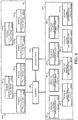
- FIG. 4 illustrates an embodiment of a system 400 for a mobile device having multiple antennas configured to be mapped to multiple transceivers using SNR measurements and touch sensors.
- System 400 may represent some embodiments of system 100, system 200, and system 300 of FIGS. 1-3 , respectively.
- System 400 includes: antennas 110, transceivers 120, selector circuit 130, processor 140, touch sensors 310, and SNR measurement collectors 410.
- System 400 may be present in a mobile device, such as a cellular phone. System 400 may also be present in other devices that communicate wirelessly.
- each transceiver may be associated with a corresponding SNR (signal-to-noise ratio) measurement collector of SNR measurement collectors 410 (e.g., SNR measurement collector 410-3 collects SNR measurements for transceiver 120-3).
- An SNR measurement collector of SNR measurement collectors 410 may be part of each transceiver of transceivers 120 or may be a separate component.
- Each SNR measurement collector of SNR measurement collectors 410 may periodically determine, collect, and/or transmit SNR measurements to processor 140. Such periodic transmission of SNR measurements may only occur when the corresponding transceiver is actively communicating.
- SNR measurement collectors 410 each may only transmit SNR measurements to processor 140 when requested by processor 140.
- SNR measurement collectors 410 collect SNR measurements from another location in system 400, such as at selector circuit 130 or antennas 110.
- the SNR measurements received by processor 140 may be used to determine when: 1) a transceiver should be mapped to a different antenna; and/or 2) when diversity of antennas should be used for a particular transceiver.
- Processor 140 may rely on various thresholds to determine whether the antenna used should be switched and/or whether diversity of antennas should be used. For example, a first SNR threshold may be used to determine that an antenna should continue to be used, but a second antenna (diversity) should be used in addition. Similarly, the first SNR threshold may be used to determine which antenna of a plurality of antennas to set as the primary antenna for diversity reception and which antenna(s) to set as secondary. A second SNR threshold may be used to determine that the current antenna should stop being used and another antenna should be used instead. This SNR threshold may be associated with a higher noise level (i.e., a lower SNR ratio) than the first SNR threshold.
- While SNR measurements from SNR measurement collectors 410 may be used by processor 140 to determine when 1) a transceiver should be mapped to a different antenna; and/or 2) when diversity of antennas should be used, processor 140 may rely on touch data from touch sensors 310 to determine which idle antenna should be selected when an antenna/transceiver mapping is being changed or diversity is being employed. In some embodiments, the processor 140 uses touch data for a given antenna in combination with a recent SNR measurement for that antenna to determine whether to map a transceiver to the antenna.
- a recent SNR measurement for a first antenna may be compared to a predicted SNR for a second antenna that has been idle for a relatively longer time in order to choose between the two antennas or select the appropriate settings and transceivers for the two antennas.
- the SNR may be predicted based on the touch data for the second antenna.
- routing between antennas, touch sensors 310, processor 140, selector circuit 130, and transceivers 120 has been simplified. Similarly, for simplicity of FIG. 4 , routing between SNR measurement collectors 410 and processor 140 has been omitted. It should be understood that routing between these components may be present.
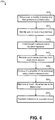
- FIG. 5 illustrates an embodiment of a method 500 for mapping an antenna to a transceiver.
- Method 500 may be performed using system 100 of FIG. 1 , system 200 of FIG. 2 , system 300 of FIG. 3 , system 400 of FIG. 4 , or some other system for mapping an antenna to a transceiver.
- Each step of method 500 may be performed by one of the aforementioned systems. More specifically, each step of method 500 may be performed by a processor, such as processor 140 of FIGS. 1-4 .
- step 510 it may be determined that the mapping of an antenna to a transceiver is to be modified. This may be based on the transceiver not being able to effectively communicate with a corresponding wireless network (e.g., the antenna is no longer serving as an effective electromagnetic transducer).
- Modifying the mapping of an antenna to a transceiver may, for example, involve: 1) switching from use of only a first antenna to diversity of antennas (while maintaining the use of the first antenna or selecting multiple different antennas); 2) switching from use of diversity of antennas to use of a single antenna (which may be one of the diversity antennas being used or a different antenna); 3) switching from use of only a first antenna to use of only a second antenna; or 4) switching from diversity of multiple antennas to diversity using some or all different antennas.
- Step 510 may be performed, for example, by the processor 140 or other such means for determining.
- one or more idle antennas may be identified. This may involve determining which antennas are not currently mapped to a transceiver.
- An idle antenna may also be an antenna that is mapped to a transceiver, but the transceiver is not communicating using the antenna.
- Idle antennas may have previously been mapped to one or more transceivers that use a variety of radio technologies and/or frequencies for communication.
- a processor may assess a storage device, such as memory, to determine which antennas are currently mapped to a transceiver and which are not. In some embodiments, the processor may poll transceivers to determine which are actively communicating and which are idle (for example, linked with idle antennas or disconnected from all antennas).
- An idle transceiver may be defined as a transceiver that has not communicated for some threshold period of time, such as one second, one minute, or one hour, for example.
- the plurality of idle antennas may be analyzed. In some embodiments, this may involve accessing touch data that identifies how much an idle antenna is contacting a physical entity, such as a user's hand. Analyzing the plurality of idle antennas may involve analyzing a listing (or other data storage structure) that provides priority or default mapping information for transceivers and/or antennas. For example, as previously detailed, while each antenna may be a wideband antenna that is capable of serving as an effective electromagnetic transducer for multiple radio technologies and/or frequencies, some antennas may be more effective at communicating using certain radio technologies and/or frequencies. As such, analyzing the plurality of idle antennas may involve comparing which antennas are idle against a list of preferred antennas for particular radio technologies.
- Table 1 CDMA Transceiver Bluetooth Transceiver LTE Transceiver WLAN Transceiver Antenna 1 3 4 1 4 Antenna 2 1 3 4 2 Antenna 3 2 1 3 1 Antenna 4 4 2 2 3
- Table 1 provides an example listing of the prioritization of antennas by radio technology.
- the device has four antennas and four transceivers that each use a different radio technology.
- the highest prioritized antenna is antenna 2. Therefore, if antenna 2 is idle, antenna 2 may be used for CDMA communication. If antenna 2 is not available (e.g., it is in contact with a physical entity and/or it is in use by another transceiver), antenna 3, the next antenna listed for priority for the CDMA transceiver, may be used.
- the prioritization of other transceivers may be the same or different from the CDMA transceiver. For instance, in some embodiments, each transceiver may have a different highest priority (default) antenna. Step 530 may be performed, for example, by the processor 140 or other such means for analyzing.
- one or more idle antennas may be mapped to the transceiver determined at step 510. These idle antennas may have previously been used for communication with transceivers of other radio technologies and/or frequencies.
- the first antenna may be unmapped from the transceiver. If diversity is being used, the first antenna may remain mapped to the transceiver.
- an indication may be transmitted to a selector circuit to implement the mapping assigned at step 540. As previously detailed, if soft switching is being used, the mapping change may result in changes to only the memory addresses of the processor or selector circuit where information of the transceiver and/or the antennas is written and/or read.
- Step 540 may be performed, for example, by the processor 140, a separate selector circuit (e.g. the selector circuit 130 when implemented separate from the processor 140), or other such means for mapping.
- FIG. 6 illustrates an embodiment of a method for mapping an antenna to a transceiver based on touch data from touch sensors.
- Method 600 may be performed using system 100 of FIG. 1 , system 200 of FIG. 2 , system 300 of FIG. 3 , system 400 of FIG. 4 , or some other system for mapping an antenna to a transceiver.
- Each step of method 600 may be performed by one of the aforementioned systems. More specifically, steps of method 600 may be performed by a processor, such as processor 140 of FIGS. 1-4 .
- Method 600 may represent a more detailed embodiment of method 500.
- step 610 it may be determined that the mapping of an antenna to a transceiver is to be modified.
- the determination to change the mapping of an antenna to a transceiver may be based on SNR measurements and/or touch data. Due to poor signal quality, SNR measurements may reflect a high level of noise, thus resulting in the transceiver not being able to effectively communicate with a corresponding wireless network.
- Modifying the mapping of an antenna to a transceiver may involve, for example: 1) switching from use of only a first antenna to diversity of antennas (while maintaining the use of the first antenna or selecting multiple different antennas); 2) switching from use of diversity of antennas to use of a single antenna (which may be one of the diversity antennas being used or a different antenna); 3) switching from use of only a first antenna to use of only a second antenna; or 4) switching from diversity of multiple antennas to diversity using some or all different antennas.
- Step 610 may be performed, for example, by the processor 140 or other such means for determining.
- one or more idle antennas may be identified. This may involve determining which antennas are not currently mapped to a transceiver. An idle antenna may also be an antenna that is mapped to a transceiver, but the transceiver is not communicating using the antenna. Idle antennas may have previously been mapped to one or more transceivers that use a variety of radio technologies and/or frequencies for communication.
- a processor may assess a storage device, such as memory, to determine which antennas are currently assigned to a transceiver and which are not. In some embodiments, the processor may poll transceivers to determine which are actively communicating and which are idle (for example, linked with idle antennas or disconnected from all antennas).
- An idle transceiver may be defined as a transceiver that has not communicated for some threshold period of time, such as one second, one minute, or one hour. Step 620 may be performed, for example, by the processor 140 or other such means for identifying.
- one or more touch sensors may collect touch data. This may involve each touch sensor detecting 1) whether a physical entity, such as a hand, is in contact with its corresponding antenna; and 2) if a physical entity is in contact with the corresponding antenna, what degree of contact is present.
- the touch data collected by each touch sensor may be represented as a number, such as from 0-10, wherein 0 indicates no contact and 10 indicates 100% contact between the antenna and the physical entity.
- Such a measurement scale is for example purposes only: other scales or forms for measuring contact between an antenna and a physical entity may be possible.
- Step 630 may be performed, for example, by the touch sensors 310 or other such means for collecting touch data.
- touch data may be received by the processor from one or more touch sensors. This may involve transmitting, by the processor, a message to one or more touch sensors to request that touch data be transmitted to the processor. In some embodiments, touch data may automatically be transmitted by touch sensors to the processor periodically. For instance, touch sensors may transmit touch data to the processor once per second. The touch data received by the processor may be stored and linked with a corresponding antenna. Step 640 may be performed, for example, by the processor 140 or other such means for receiving.
- the plurality of idle antennas may be analyzed. This analysis may involve using the touch data received at step 640 that identifies how much an idle antenna is contacting a physical entity.
- the idle antennas may be ranked according to an amount of contact with the physical entity. For example, an idle antenna that has no contact with a physical entity may be more likely to serve as an effective electromagnetic transducer than an idle antenna that has 50% contact with a physical entity because the communication path is less likely to be obstructed and/or the electromagnetic characteristics of the antenna for transmission and/or reception of data is less affected.
- Step 650 may be performed, for example, by the processor 140 or other such means for analyzing.
- a list of preferred antennas for particular radio technologies may be used.
- weighting between touch data and the listing may be used. For example, if any contact is detected with an idle antenna, that antenna may be ignored in favor of another antenna with no contact with a physical entity but a lower priority.
- a priority listing may only be used when multiple idle antennas have the same or no contact with a physical entity as indicated by touch data.
- equation 1 provides an example of how touch data related to antennas and corresponding priority information may be used to select an antenna.
- a score is determined based on a weighting factor w (between zero and one), a priority P of an antenna for a transceiver associated with a particular radio technology, and a touch measurement T for the antenna.
- the weighting factor may be selected based on whether more weight is to be given to the priority listing or the touch data.
- T the greater the touch measurement, the more contact between the antenna and a physical entity.
- P a numerical score may be provided, such as in table 1, for each antenna for a particular technology.
- the antenna that evaluates to the lowest score may be the antenna selected to be mapped to the transceiver.
- equation 1 is for exemplary purposes only: other forms of equations to evaluate which antenna to select may be used. In some embodiments, only touch sense measurements may be used to determine which antenna to select.
- one or more idle antennas may be mapped to the transceiver determined at step 610. This may involve unmapping the first antenna from the transceiver. If diversity is being used, the first antenna may remain mapped to the transceiver.
- an indication may be transmitted to a selector circuit to implement the mapping assigned at step 660. As previously detailed, if soft switching is being used, the mapping change may result in changes to only the memory addresses of the processor or selector circuit where information of the transceiver and/or the antennas is written and/or read. Step 660 may be performed, for example, by the processor 140, a separate selector circuit (e.g. the selector circuit 130 when implemented separate from the processor 140), or other such means for mapping.
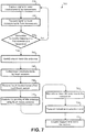
- FIG. 7 illustrates an embodiment of a method 700 for mapping an antenna to a transceiver based on indications from signal-to-noise measurements and touch data from touch sensors.
- Method 700 may be performed using system 100 of FIG. 1 , system 200 of FIG. 2 , system 300 of FIG. 3 , system 400 of FIG. 4 , or some other system for mapping an antenna to a transceiver.
- Each step of method 700 may be performed by one of the aforementioned systems. More specifically, steps of method 700 may be performed by a processor, such as processor 140 of FIGS. 1-3 .
- Method 700 may represent a more detailed embodiment of method 500 of FIG. 5 and/or method 600 of FIG. 6 .
- SNR measurements may be captured by each transceiver that is actively communicating via an antenna.
- the SNR measurements are determined or collected by components such as SNR measurement collectors, which may be integral with or separate from the transceivers.
- SNR measurement collectors may measure the SNR at the transceivers or at some other location, such as the input from each antenna or the input or output from a selector circuit.
- the SNR measurements may be captured periodically, such as once every 100 ms, or in response to a request from the processor, a transceiver may transmit an SNR measurement to the processor.
- the SNR measurements from one or more transceivers or SNR measurement collectors may be received by the processor.
- step 730 it may be determined whether the mapping of an antenna to a transceiver is to be modified.
- the determination to change the mapping of an antenna to a transceiver may be based on SNR measurements.
- SNR measurement thresholds may be used to determine whether the antenna should be switched and/or whether diversity of antennas should be used. For example, a first SNR measurement threshold may be used to determine that an antenna should continue to be used but a second antenna (diversity) should be used to achieve a sufficient communication path.
- a second SNR measurement threshold may be used to determine that the current antenna should stop being used and another antenna should be used instead. This second SNR measurement threshold may be associated with a higher noise level than the first SNR threshold.
- method 700 may return to step 710. This loop of steps may repeat. If an SNR measurement exceeds one of the thresholds, the mapping of one or more antennas to the transceiver having the SNR measurements exceeding one of the thresholds may be modified.
- modifying the mapping of an antenna to a transceiver of step 730 may involve, for example: 1) switching from use of only a first antenna to diversity of antennas (while maintaining the use of the first antenna or selecting multiple different antennas); 2) switching from use of diversity of antennas to use of a single antenna (which may be one of the diversity antennas being used or a different antenna); 3) switching from use of only a first antenna to use of only a second antenna; or 4) switching from diversity of multiple antennas to diversity using some or all different antennas.
- one or more idle antennas may be identified. This may involve determining which antennas are not currently mapped to a transceiver.
- An idle antenna may also be an antenna that is mapped to a transceiver, but the transceiver is not communicating using the antenna.
- Idle antennas may have previously been mapped to one or more transceivers that use a variety of radio technologies and/or frequencies for communication.
- a processor may assess a storage device, such as memory, to determine which antennas are currently assigned to a transceiver and which are not. In some embodiments, the processor may poll transceivers to determine which are actively communicating and which are idle (and are, therefore, linked with idle antennas).
- An idle transceiver may be defined as a transceiver that has not communicated for some threshold period of time, such as one second, one minute, or one hour.
- one or more touch sensors may collect touch data associated with corresponding antennas. This may involve each touch sensor detecting 1) whether a physical entity, such as a hand, is in contact with its corresponding antenna; and 2) if a physical entity is in contact with the corresponding antenna, what degree of contact is present.
- touch data may be received by the processor from one or more touch sensors. This may involve transmitting, by the processor, a message to one or more touch sensors to request that touch data be transmitted to the processor.
- touch data may automatically be transmitted by touch sensors to the processor periodically. For instance, touch sensors may transmit data to the processor once per second.
- the touch data received by the processor may be, at least temporarily, stored and linked with a corresponding antenna.
- the plurality of idle antennas may be analyzed. This analysis may involve using the touch data received at step 760 that identifies how much an idle antenna is contacting a physical entity.
- the idle antennas may be ranked according to an amount of contact with the physical entity. For example, an idle antenna that has no contact with a physical entity may be more likely to serve as an effective electromagnetic transducer than an idle antenna that has 50% contact with a physical entity because the communication path is likely less obstructed and/or the electromagnetic characteristics of the antenna for transmission and/or reception of data is less affected.
- a listing of preferred antennas for particular transceivers may be used, such as detailed in relation to step 650 of method 600 of FIG. 6 .
- one or more idle antennas may be mapped to the transceiver determined at step 730. This may involve unmapping the first antenna from the transceiver. If diversity is being used, the first antenna may remain mapped to the transceiver.
- an indication may be transmitted to a selector circuit to implement the mapping assigned at step 780. As previously detailed, if soft switching is being used, the mapping change may result in changes to only the memory addresses of the processor or selector circuit where information of the transceiver and/or the antennas is written and/or read.
- the selector circuit may map the antenna to the transceiver. Step 780 may be performed, for example, by a processor (e.g. the processor 140), a separate selector circuit (e.g. the selector circuit 130 when implemented separate from the processor 140), or by some other means for mapping.
- FIG. 8 illustrates an embodiment of such a computer system.
- a computer system as illustrated in FIG. 8 may function as the previously mentioned computer system.
- computer system 800 can execute software components and/or a task generator.
- FIG. 8 provides a schematic illustration of one embodiment of a computer system 800 that can perform the methods provided by various other embodiments, as described herein. It should be noted that FIG. 8 is meant only to provide a generalized illustration of various components, any or all of which may be utilized as appropriate. FIG. 8 , therefore, broadly illustrates how individual system elements may be implemented in a relatively separated or relatively more integrated manner.
- the computer system 800 is shown comprising hardware elements that can be electrically coupled via a bus 805 (or may otherwise be in communication, as appropriate).
- the bus 805 or a component or device associated with the bus 805 is used to implement the selector circuit 130.
- the hardware elements may include one or more processors 810, including without limitation one or more general-purpose processors and/or one or more special-purpose processors (such as digital signal processing chips, graphics acceleration processors, and/or the like); one or more input devices 815, which can include without limitation a mouse, a keyboard and/or the like; and one or more output devices 820, which can include without limitation a display device, a printer and/or the like.
- the processor 810 may be used to implement or may be implemented in the processor 140.
- the selector circuit 130 is implemented by the processor 810.
- One or more of the touch sensors 310 may be implemented by the input device 815.
- the computer system 800 may further include (and/or be in communication with) one or more non-transitory storage devices 825, which can comprise, without limitation, local and/or network accessible storage, and/or can include, without limitation, a disk drive, a drive array, an optical storage device, solid-state storage device such as a random access memory (“RAM”) and/or a read-only memory (“ROM”), which can be programmable, flash-updateable and/or the like.
- RAM random access memory
- ROM read-only memory
- Such storage devices may be configured to implement any appropriate data stores, including without limitation, various file systems, database structures, and/or the like.
- the computer system 800 might also include a communications subsystem 830, which can include without limitation a modem, a network card (wireless or wired), an infrared communication device, a wireless communication device and/or chipset (such as a BluetoothTM device, an 802.11 device, a WiFi device, a WiMax device, cellular communication facilities, etc.), and/or the like.
- the communications subsystem 830 may permit data to be exchanged with a network (such as the network described below, to name one example), other computer systems, and/or any other devices described herein.
- one or more of the transceivers 120 are implemented by the communications subsystem 830.
- one or more of the SNR measurement collectors 410 are implemented by the communications subsystem 830.
- the computer system 800 will further comprise a working memory 835, which can include a RAM or ROM device, as described above.
- the computer system 800 also can comprise software elements, shown as being currently located within the working memory 835, including an operating system 840, device drivers, executable libraries, and/or other code, such as one or more application programs 845, which may comprise computer programs provided by various embodiments, and/or may be designed to implement methods, and/or configure systems, provided by other embodiments, as described herein.
- an operating system 840 operating system 840
- device drivers executable libraries
- application programs 845 which may comprise computer programs provided by various embodiments, and/or may be designed to implement methods, and/or configure systems, provided by other embodiments, as described herein.
- code and/or instructions can be used to configure and/or adapt a general purpose computer (or other device) to perform one or more operations in accordance with the described methods.
- a set of these instructions and/or code might be stored on a non-transitory computer-readable storage medium, such as the storage device(s) 825 described above.
- the storage medium might be incorporated within a computer system, such as the computer system 800.
- the storage medium might be separate from a computer system (e.g., a removable medium, such as a compact disc), and/or provided in an installation package, such that the storage medium can be used to program, configure and/or adapt a general purpose computer with the instructions/code stored thereon.
- These instructions might take the form of executable code, which is executable by the computer system 800 and/or might take the form of source and/or installable code, which, upon compilation and/or installation on the computer system 800 (e.g., using any of a variety of generally available compilers, installation programs, compression/decompression utilities, etc.) then takes the form of executable code.
- some embodiments may employ a computer system (such as the computer system 800) to perform methods in accordance with various embodiments of the invention.
- some or all of the procedures of such methods are performed by the computer system 800 in response to processor 810 executing one or more sequences of one or more instructions (which might be incorporated into the operating system 840 and/or other code, such as an application program 845) contained in the working memory 835.
- Such instructions may be read into the working memory 835 from another computer-readable medium, such as one or more of the storage device(s) 825.
- execution of the sequences of instructions contained in the working memory 835 might cause the processor(s) 810 to perform one or more procedures of the methods described herein.
- machine-readable medium and “computer-readable medium,” as used herein, refer to any medium that participates in providing data that causes a machine to operate in a specific fashion.
- various computer-readable media might be involved in providing instructions/code to processor(s) 810 for execution and/or might be used to store and/or carry such instructions/code.
- a computer-readable medium is a physical and/or tangible storage medium.
- Such a medium may take the form of a non-volatile media or volatile media.
- Non-volatile media include, for example, optical and/or magnetic disks, such as the storage device(s) 825.
- Volatile media include, without limitation, dynamic memory, such as the working memory 835.
- Common forms of physical and/or tangible computer-readable media include, for example, a floppy disk, a flexible disk, hard disk, magnetic tape, or any other magnetic medium, a CD-ROM, any other optical medium, punchcards, papertape, any other physical medium with patterns of holes, a RAM, a PROM, EPROM, a FLASH-EPROM, any other memory chip or cartridge, or any other medium from which a computer can read instructions and/or code.
- Various forms of computer-readable media may be involved in carrying one or more sequences of one or more instructions to the processor(s) 810 for execution.
- the instructions may initially be carried on a magnetic disk and/or optical disc of a remote computer.
- a remote computer might load the instructions into its dynamic memory and send the instructions as signals over a transmission medium to be received and/or executed by the computer system 800.
- the communications subsystem 830 (and/or components thereof) generally will receive signals, and the bus 805 then might carry the signals (and/or the data, instructions, etc., carried by the signals) to the working memory 835, from which the processor(s) 810 retrieves and executes the instructions.
- the instructions received by the working memory 835 may optionally be stored on a storage device 825 either before or after execution by the processor(s) 810.
- configurations may be described as a process which is depicted as a flow diagram or block diagram. Although each may describe the operations as a sequential process, many of the operations can be performed in parallel or concurrently. In addition, the order of the operations may be rearranged. A process may have additional steps not included in the figure or may omit one or more illustrated steps.
- examples of the methods may be implemented by hardware, software, firmware, middleware, microcode, hardware description languages, or any combination thereof.
- the program code or code segments to perform the necessary tasks may be stored in a non-transitory computer-readable medium such as a storage medium. Processors may perform the described tasks.
Landscapes
- Engineering & Computer Science (AREA)
- Computer Networks & Wireless Communication (AREA)
- Signal Processing (AREA)
- Quality & Reliability (AREA)
- Mobile Radio Communication Systems (AREA)
- Radio Transmission System (AREA)
- Transceivers (AREA)
Applications Claiming Priority (2)
| Application Number | Priority Date | Filing Date | Title |
|---|---|---|---|
| US13/209,288 US8744502B2 (en) | 2011-08-12 | 2011-08-12 | Antenna to transceiver mapping of a multimode wireless device |
| PCT/US2012/049052 WO2013025345A1 (en) | 2011-08-12 | 2012-07-31 | Antenna to transceiver mapping of a multimode wireless device |
Publications (2)
| Publication Number | Publication Date |
|---|---|
| EP2742598A1 EP2742598A1 (en) | 2014-06-18 |
| EP2742598B1 true EP2742598B1 (en) | 2019-05-15 |
Family
ID=46642638
Family Applications (1)
| Application Number | Title | Priority Date | Filing Date |
|---|---|---|---|
| EP12745962.6A Active EP2742598B1 (en) | 2011-08-12 | 2012-07-31 | Antenna to transceiver mapping of a multimode wireless device |
Country Status (7)
| Country | Link |
|---|---|
| US (2) | US8744502B2 (es) |
| EP (1) | EP2742598B1 (es) |
| JP (2) | JP2014527357A (es) |
| KR (2) | KR102019494B1 (es) |
| CN (2) | CN103828248B (es) |
| TW (1) | TW201318440A (es) |
| WO (1) | WO2013025345A1 (es) |
Families Citing this family (29)
| Publication number | Priority date | Publication date | Assignee | Title |
|---|---|---|---|---|
| US8744502B2 (en) | 2011-08-12 | 2014-06-03 | Qualcomm Incorporated | Antenna to transceiver mapping of a multimode wireless device |
| US8934561B2 (en) | 2011-12-28 | 2015-01-13 | Nokia Siemens Networks Oy | Cell clustering and aperture selection |
| US9042941B2 (en) * | 2011-12-28 | 2015-05-26 | Nokia Solutions And Networks Oy | Uplink grouping and aperture apparatus |
| US9287953B2 (en) | 2012-05-21 | 2016-03-15 | Qualcomm Incorporated | Systems, apparatus, and methods for antenna selection |
| US9257744B2 (en) | 2012-05-21 | 2016-02-09 | Qualcomm Incorporated | Devices, systems, and methods for adjusting probing distances |
| US8913972B2 (en) | 2012-10-11 | 2014-12-16 | Nokia Siemens Networks Oy | Antenna clustering for multi-antenna aperture selection |
| WO2014175919A1 (en) | 2013-04-26 | 2014-10-30 | Intel IP Corporation | Shared spectrum reassignment in a spectrum sharing context |
| US20150017923A1 (en) * | 2013-07-12 | 2015-01-15 | Qualcomm Incorporated | Adaptive rf control for lte measurements |
| US9363849B2 (en) * | 2014-03-17 | 2016-06-07 | Qualcomm Incorporated | Single antenna sharing for multiple wireless connections |
| CN104243005B (zh) * | 2014-09-03 | 2017-12-29 | 华为技术有限公司 | 天线功能扩展装置、设备和对天线进行功能扩展的方法 |
| CN104270166B (zh) * | 2014-10-17 | 2016-07-20 | 中磊电子(苏州)有限公司 | 收发异质射频信号的无线通讯装置 |
| US9628166B2 (en) | 2015-04-03 | 2017-04-18 | Qualcomm Incorporated | Shared antenna loss detection and recovery |
| KR20160141560A (ko) * | 2015-06-01 | 2016-12-09 | 삼성전기주식회사 | 무선 통신 장치 및 이를 이용한 운용 방법 |
| TWI563277B (en) * | 2015-06-10 | 2016-12-21 | Wistron Neweb Corp | Radar and method for switching to enable array antenna |
| CN106257303B (zh) * | 2015-06-16 | 2019-02-12 | 启碁科技股份有限公司 | 雷达及切换致能阵列天线的方法 |
| DE102015211278A1 (de) * | 2015-06-18 | 2016-12-22 | Audi Ag | Verfahren und Vorrichtung zur Signalübertragung |
| US9628136B2 (en) * | 2015-06-25 | 2017-04-18 | Motorola Mobility Llc | Methods and apparatus for controlling multiple-input and multiple-output operation in a communication device based on a position sensor input |
| US10554240B2 (en) * | 2015-12-28 | 2020-02-04 | Apple, Inc. | Wireless electronic device with radio-frequency sensors |
| EP3422609A1 (en) * | 2017-06-30 | 2019-01-02 | Thomson Licensing | A method for detecting an external antenna connected to a communication device |
| CN108134199B (zh) * | 2017-12-29 | 2021-04-20 | Tcl移动通信科技(宁波)有限公司 | 一种移动终端天线及其切换方法 |
| CN112134588B (zh) | 2018-03-16 | 2022-03-15 | Oppo广东移动通信有限公司 | 多路选择开关及相关产品 |
| CN108390693A (zh) | 2018-03-16 | 2018-08-10 | 广东欧珀移动通信有限公司 | 多路选择开关及相关产品 |
| CN108512567B (zh) * | 2018-03-16 | 2020-06-23 | Oppo广东移动通信有限公司 | 多路选择开关、射频系统和无线通信设备 |
| DE102018204639A1 (de) * | 2018-03-27 | 2019-10-02 | Bayerische Motoren Werke Aktiengesellschaft | Kommunikationsvorrichtung, Fahrzeug, Verfahren und Computerprogramm zur Kommunikation in einem Mobilkommunikationssystem |
| CN111182592B (zh) * | 2018-12-28 | 2021-09-14 | 维沃移动通信有限公司 | 接收模式切换的方法及终端 |
| US11316610B2 (en) * | 2019-03-08 | 2022-04-26 | Facebook Technologies, Llc | Systems and methods for beamforming |
| JP2020170919A (ja) | 2019-04-02 | 2020-10-15 | 株式会社村田製作所 | 高周波信号送受信回路 |
| US11469783B2 (en) * | 2019-05-14 | 2022-10-11 | Cypress Semiconductor Corporation | Apparatus, systems, and methods for selecting a wireless device antenna for communication |
| CN112436876A (zh) * | 2019-08-26 | 2021-03-02 | 中兴通讯股份有限公司 | 5g天线控制方法和装置、5g终端及计算机可读存储介质 |
Citations (2)
| Publication number | Priority date | Publication date | Assignee | Title |
|---|---|---|---|---|
| EP1533918A2 (en) * | 2003-11-21 | 2005-05-25 | Pioneer Corporation | Diversity receiver |
| US20080132283A1 (en) * | 2006-11-30 | 2008-06-05 | Motorola, Inc. | Mobile station that provides feedback indicative of whether it is being properly held |
Family Cites Families (16)
| Publication number | Priority date | Publication date | Assignee | Title |
|---|---|---|---|---|
| JP2002217803A (ja) * | 2001-01-15 | 2002-08-02 | Nec Access Technica Ltd | 携帯無線端末装置 |
| US7574603B2 (en) | 2003-11-14 | 2009-08-11 | Microsoft Corporation | Method of negotiating security parameters and authenticating users interconnected to a network |
| TW200640170A (en) * | 2005-02-17 | 2006-11-16 | Interdigital Tech Corp | Method and apparatus for selecting a beam combination of multiple-input multiple-output antennas |
| US20080051165A1 (en) | 2006-08-28 | 2008-02-28 | Motorola, Inc. | Rf power control using proximity sensor |
| US7778678B2 (en) | 2006-10-10 | 2010-08-17 | Panasonic Corporation | Radio control device |
| US8054837B2 (en) | 2007-04-30 | 2011-11-08 | Yim Tu Investments Ltd., Llc | Multiuser scheduling for MIMO broadcast channels with finite rate feedback |
| JP5025356B2 (ja) | 2007-07-10 | 2012-09-12 | キヤノン株式会社 | 通信システム、情報処理装置ならびに通信制御方法 |
| US8085734B2 (en) | 2008-03-14 | 2011-12-27 | Lantiq Deutschland Gmbh | System and method for dynamic receive diversity allocation |
| US20090267828A1 (en) * | 2008-04-28 | 2009-10-29 | Kabushiki Kaisha Toshiba | GPS Signal Receiving Apparatus |
| JP5228648B2 (ja) * | 2008-06-26 | 2013-07-03 | 富士通株式会社 | 端末装置及びそのダイバーシティアンテナ制御方法 |
| US8957813B2 (en) * | 2009-03-13 | 2015-02-17 | Pong Research Corporation | External case for redistribution of RF radiation away from wireless communication device user and wireless communication device incorporating RF radiation redistribution elements |
| US20100120466A1 (en) | 2008-11-12 | 2010-05-13 | Nokia Corporation | Multi-mode antenna switching |
| KR101650331B1 (ko) | 2009-05-06 | 2016-09-05 | 삼성전자 주식회사 | 복수 개의 안테나를 포함하는 단말기 및 그의 운용 방법 |
| US9155103B2 (en) * | 2009-06-01 | 2015-10-06 | Qualcomm Incorporated | Coexistence manager for controlling operation of multiple radios |
| US20110250926A1 (en) * | 2009-12-21 | 2011-10-13 | Qualcomm Incorporated | Dynamic antenna selection in a wireless device |
| US8744502B2 (en) | 2011-08-12 | 2014-06-03 | Qualcomm Incorporated | Antenna to transceiver mapping of a multimode wireless device |
-
2011
- 2011-08-12 US US13/209,288 patent/US8744502B2/en active Active
-
2012
- 2012-07-31 JP JP2014525050A patent/JP2014527357A/ja active Pending
- 2012-07-31 CN CN201280044233.0A patent/CN103828248B/zh active Active
- 2012-07-31 KR KR1020147021806A patent/KR102019494B1/ko active IP Right Grant
- 2012-07-31 WO PCT/US2012/049052 patent/WO2013025345A1/en unknown
- 2012-07-31 KR KR1020147006672A patent/KR20140048325A/ko active Search and Examination
- 2012-07-31 EP EP12745962.6A patent/EP2742598B1/en active Active
- 2012-07-31 CN CN201510524222.8A patent/CN105227220B/zh active Active
- 2012-08-09 TW TW101128810A patent/TW201318440A/zh unknown
-
2014
- 2014-04-23 US US14/260,079 patent/US9143209B2/en active Active
- 2014-12-16 JP JP2014253909A patent/JP2015092706A/ja active Pending
Patent Citations (2)
| Publication number | Priority date | Publication date | Assignee | Title |
|---|---|---|---|---|
| EP1533918A2 (en) * | 2003-11-21 | 2005-05-25 | Pioneer Corporation | Diversity receiver |
| US20080132283A1 (en) * | 2006-11-30 | 2008-06-05 | Motorola, Inc. | Mobile station that provides feedback indicative of whether it is being properly held |
Also Published As
| Publication number | Publication date |
|---|---|
| EP2742598A1 (en) | 2014-06-18 |
| WO2013025345A1 (en) | 2013-02-21 |
| KR20140048325A (ko) | 2014-04-23 |
| JP2014527357A (ja) | 2014-10-09 |
| JP2015092706A (ja) | 2015-05-14 |
| US9143209B2 (en) | 2015-09-22 |
| KR102019494B1 (ko) | 2019-09-06 |
| KR20140102773A (ko) | 2014-08-22 |
| US8744502B2 (en) | 2014-06-03 |
| US20140235260A1 (en) | 2014-08-21 |
| CN105227220B (zh) | 2020-05-26 |
| CN103828248A (zh) | 2014-05-28 |
| CN105227220A (zh) | 2016-01-06 |
| TW201318440A (zh) | 2013-05-01 |
| US20130040671A1 (en) | 2013-02-14 |
| CN103828248B (zh) | 2015-09-30 |
Similar Documents
| Publication | Publication Date | Title |
|---|---|---|
| EP2742598B1 (en) | Antenna to transceiver mapping of a multimode wireless device | |
| US10880884B2 (en) | Dynamic space, frequency and time domain coexistence | |
| CN108282166B (zh) | 天线共存互扰处理方法、装置、存储介质及电子设备 | |
| EP3376675B1 (en) | System and method for coordinating multiple radio transceivers within the same device platform | |
| CN109905142B (zh) | 自适应多路复用和发送/接收分集 | |
| EP3456104B1 (en) | Communication device and method therein for handling operating modes in wireless communication network | |
| US10715232B2 (en) | Antenna configuration method, terminal device, and antenna circuit | |
| CN102640536A (zh) | 移动站、网络和切换控制方法 | |
| CN108513718A (zh) | 一种网络通信方法和终端 | |
| US20080108358A1 (en) | Interference mitigation and recovery | |
| KR20080066257A (ko) | Cr 환경의 통신 방법 및 그 장치 | |
| US20190075518A1 (en) | Systems and methods for low power operation of a wireless communication device | |
| CN105743591A (zh) | 一种rssi检测的控制方法,接入设备及终端设备 | |
| WO2021016027A1 (en) | Multiple concurrent bandwidth parts for a base station of a cellular network | |
| CN102833788A (zh) | 上行数据发送方法、装置及系统 | |
| US20190342811A1 (en) | Network-Congestion Based Connection Manager | |
| CN113079558B (zh) | 一种功耗控制方法、芯片系统及终端设备 | |
| CN104125603B (zh) | 一种基站向通信终端发送指示消息的方法、设备及系统 | |
| WO2024169910A1 (zh) | 数据传输方法、装置、设备和存储介质 | |
| JP2015097328A (ja) | サーバ、情報収集システム及び情報収集方法 | |
| EP4358601A1 (en) | Implementation of attachment for passive iot device communication with ambient energy source | |
| EP4358599A1 (en) | Attachment procedure for passive iot device communication with ambient energy source | |
| US9781680B2 (en) | Terminal apparatus, communication system, communication method for transmitting the measured positional information | |
| CN108886696A (zh) | 一种发送信号、接收信号的方法及装置 |
Legal Events
| Date | Code | Title | Description |
|---|---|---|---|
| PUAI | Public reference made under article 153(3) epc to a published international application that has entered the european phase |
Free format text: ORIGINAL CODE: 0009012 |
|
| 17P | Request for examination filed |
Effective date: 20140311 |
|
| AK | Designated contracting states |
Kind code of ref document: A1 Designated state(s): AL AT BE BG CH CY CZ DE DK EE ES FI FR GB GR HR HU IE IS IT LI LT LU LV MC MK MT NL NO PL PT RO RS SE SI SK SM TR |
|
| AX | Request for extension of the european patent |
Extension state: BA ME |
|
| STAA | Information on the status of an ep patent application or granted ep patent |
Free format text: STATUS: EXAMINATION IS IN PROGRESS |
|
| 17Q | First examination report despatched |
Effective date: 20170907 |
|
| RIC1 | Information provided on ipc code assigned before grant |
Ipc: H01Q 21/28 20060101ALI20180928BHEP Ipc: H04B 7/0404 20170101ALI20180928BHEP Ipc: H01Q 1/24 20060101AFI20180928BHEP Ipc: H04B 7/06 20060101ALN20180928BHEP Ipc: H04W 48/18 20090101ALN20180928BHEP Ipc: H04W 52/02 20090101ALI20180928BHEP Ipc: H04W 88/06 20090101ALI20180928BHEP Ipc: H04B 7/08 20060101ALN20180928BHEP |
|
| GRAP | Despatch of communication of intention to grant a patent |
Free format text: ORIGINAL CODE: EPIDOSNIGR1 |
|
| STAA | Information on the status of an ep patent application or granted ep patent |
Free format text: STATUS: GRANT OF PATENT IS INTENDED |
|
| RIC1 | Information provided on ipc code assigned before grant |
Ipc: H04B 7/06 20060101ALN20181023BHEP Ipc: H01Q 21/28 20060101ALI20181023BHEP Ipc: H04B 7/08 20060101ALN20181023BHEP Ipc: H04W 52/02 20090101ALI20181023BHEP Ipc: H01Q 1/24 20060101AFI20181023BHEP Ipc: H04W 48/18 20090101ALN20181023BHEP Ipc: H04B 7/0404 20140618ALI20181023BHEP Ipc: H04W 88/06 20090101ALI20181023BHEP |
|
| INTG | Intention to grant announced |
Effective date: 20181114 |
|
| RIC1 | Information provided on ipc code assigned before grant |
Ipc: H04B 7/0404 20170101ALI20181023BHEP Ipc: H04W 52/02 20090101ALI20181023BHEP Ipc: H04W 48/18 20090101ALN20181023BHEP Ipc: H04W 88/06 20090101ALI20181023BHEP Ipc: H04B 7/06 20060101ALN20181023BHEP Ipc: H01Q 1/24 20060101AFI20181023BHEP Ipc: H01Q 21/28 20060101ALI20181023BHEP Ipc: H04B 7/08 20060101ALN20181023BHEP |
|
| RIC1 | Information provided on ipc code assigned before grant |
Ipc: H04B 7/06 20060101ALN20181023BHEP Ipc: H04W 52/02 20090101ALI20181023BHEP Ipc: H01Q 1/24 20060101AFI20181023BHEP Ipc: H04B 7/0404 20170101ALI20181023BHEP Ipc: H04W 48/18 20090101ALN20181023BHEP Ipc: H04W 88/06 20090101ALI20181023BHEP Ipc: H04B 7/08 20060101ALN20181023BHEP Ipc: H01Q 21/28 20060101ALI20181023BHEP |
|
| GRAJ | Information related to disapproval of communication of intention to grant by the applicant or resumption of examination proceedings by the epo deleted |
Free format text: ORIGINAL CODE: EPIDOSDIGR1 |
|
| STAA | Information on the status of an ep patent application or granted ep patent |
Free format text: STATUS: EXAMINATION IS IN PROGRESS |
|
| REG | Reference to a national code |
Ref country code: DE Ref legal event code: R079 Ref document number: 602012060144 Country of ref document: DE Free format text: PREVIOUS MAIN CLASS: H04B0001400000 Ipc: H01Q0001240000 |
|
| GRAR | Information related to intention to grant a patent recorded |
Free format text: ORIGINAL CODE: EPIDOSNIGR71 |
|
| GRAS | Grant fee paid |
Free format text: ORIGINAL CODE: EPIDOSNIGR3 |
|
| STAA | Information on the status of an ep patent application or granted ep patent |
Free format text: STATUS: GRANT OF PATENT IS INTENDED |
|
| GRAA | (expected) grant |
Free format text: ORIGINAL CODE: 0009210 |
|
| STAA | Information on the status of an ep patent application or granted ep patent |
Free format text: STATUS: THE PATENT HAS BEEN GRANTED |
|
| INTC | Intention to grant announced (deleted) | ||
| RIC1 | Information provided on ipc code assigned before grant |
Ipc: H04B 7/06 20060101ALN20190320BHEP Ipc: H04W 48/18 20090101ALN20190320BHEP Ipc: H04W 88/06 20090101ALI20190320BHEP Ipc: H04W 52/02 20090101ALI20190320BHEP Ipc: H01Q 1/24 20060101AFI20190320BHEP Ipc: H04B 7/0404 20170101ALI20190320BHEP Ipc: H04B 7/08 20060101ALN20190320BHEP Ipc: H01Q 21/28 20060101ALI20190320BHEP |
|
| INTG | Intention to grant announced |
Effective date: 20190404 |
|
| AK | Designated contracting states |
Kind code of ref document: B1 Designated state(s): AL AT BE BG CH CY CZ DE DK EE ES FI FR GB GR HR HU IE IS IT LI LT LU LV MC MK MT NL NO PL PT RO RS SE SI SK SM TR |
|
| AX | Request for extension of the european patent |
Extension state: BA ME |
|
| REG | Reference to a national code |
Ref country code: CH Ref legal event code: EP Ref country code: GB Ref legal event code: FG4D |
|
| REG | Reference to a national code |
Ref country code: DE Ref legal event code: R096 Ref document number: 602012060144 Country of ref document: DE |
|
| REG | Reference to a national code |
Ref country code: IE Ref legal event code: FG4D |
|
| REG | Reference to a national code |
Ref country code: NL Ref legal event code: MP Effective date: 20190515 |
|
| REG | Reference to a national code |
Ref country code: LT Ref legal event code: MG4D |
|
| PG25 | Lapsed in a contracting state [announced via postgrant information from national office to epo] |
Ref country code: LT Free format text: LAPSE BECAUSE OF FAILURE TO SUBMIT A TRANSLATION OF THE DESCRIPTION OR TO PAY THE FEE WITHIN THE PRESCRIBED TIME-LIMIT Effective date: 20190515 Ref country code: HR Free format text: LAPSE BECAUSE OF FAILURE TO SUBMIT A TRANSLATION OF THE DESCRIPTION OR TO PAY THE FEE WITHIN THE PRESCRIBED TIME-LIMIT Effective date: 20190515 Ref country code: NO Free format text: LAPSE BECAUSE OF FAILURE TO SUBMIT A TRANSLATION OF THE DESCRIPTION OR TO PAY THE FEE WITHIN THE PRESCRIBED TIME-LIMIT Effective date: 20190815 Ref country code: NL Free format text: LAPSE BECAUSE OF FAILURE TO SUBMIT A TRANSLATION OF THE DESCRIPTION OR TO PAY THE FEE WITHIN THE PRESCRIBED TIME-LIMIT Effective date: 20190515 Ref country code: ES Free format text: LAPSE BECAUSE OF FAILURE TO SUBMIT A TRANSLATION OF THE DESCRIPTION OR TO PAY THE FEE WITHIN THE PRESCRIBED TIME-LIMIT Effective date: 20190515 Ref country code: AL Free format text: LAPSE BECAUSE OF FAILURE TO SUBMIT A TRANSLATION OF THE DESCRIPTION OR TO PAY THE FEE WITHIN THE PRESCRIBED TIME-LIMIT Effective date: 20190515 Ref country code: PT Free format text: LAPSE BECAUSE OF FAILURE TO SUBMIT A TRANSLATION OF THE DESCRIPTION OR TO PAY THE FEE WITHIN THE PRESCRIBED TIME-LIMIT Effective date: 20190915 Ref country code: SE Free format text: LAPSE BECAUSE OF FAILURE TO SUBMIT A TRANSLATION OF THE DESCRIPTION OR TO PAY THE FEE WITHIN THE PRESCRIBED TIME-LIMIT Effective date: 20190515 Ref country code: FI Free format text: LAPSE BECAUSE OF FAILURE TO SUBMIT A TRANSLATION OF THE DESCRIPTION OR TO PAY THE FEE WITHIN THE PRESCRIBED TIME-LIMIT Effective date: 20190515 |
|
| PG25 | Lapsed in a contracting state [announced via postgrant information from national office to epo] |
Ref country code: BG Free format text: LAPSE BECAUSE OF FAILURE TO SUBMIT A TRANSLATION OF THE DESCRIPTION OR TO PAY THE FEE WITHIN THE PRESCRIBED TIME-LIMIT Effective date: 20190815 Ref country code: GR Free format text: LAPSE BECAUSE OF FAILURE TO SUBMIT A TRANSLATION OF THE DESCRIPTION OR TO PAY THE FEE WITHIN THE PRESCRIBED TIME-LIMIT Effective date: 20190816 Ref country code: LV Free format text: LAPSE BECAUSE OF FAILURE TO SUBMIT A TRANSLATION OF THE DESCRIPTION OR TO PAY THE FEE WITHIN THE PRESCRIBED TIME-LIMIT Effective date: 20190515 Ref country code: RS Free format text: LAPSE BECAUSE OF FAILURE TO SUBMIT A TRANSLATION OF THE DESCRIPTION OR TO PAY THE FEE WITHIN THE PRESCRIBED TIME-LIMIT Effective date: 20190515 |
|
| REG | Reference to a national code |
Ref country code: AT Ref legal event code: MK05 Ref document number: 1134501 Country of ref document: AT Kind code of ref document: T Effective date: 20190515 |
|
| PG25 | Lapsed in a contracting state [announced via postgrant information from national office to epo] |
Ref country code: SK Free format text: LAPSE BECAUSE OF FAILURE TO SUBMIT A TRANSLATION OF THE DESCRIPTION OR TO PAY THE FEE WITHIN THE PRESCRIBED TIME-LIMIT Effective date: 20190515 Ref country code: CZ Free format text: LAPSE BECAUSE OF FAILURE TO SUBMIT A TRANSLATION OF THE DESCRIPTION OR TO PAY THE FEE WITHIN THE PRESCRIBED TIME-LIMIT Effective date: 20190515 Ref country code: RO Free format text: LAPSE BECAUSE OF FAILURE TO SUBMIT A TRANSLATION OF THE DESCRIPTION OR TO PAY THE FEE WITHIN THE PRESCRIBED TIME-LIMIT Effective date: 20190515 Ref country code: DK Free format text: LAPSE BECAUSE OF FAILURE TO SUBMIT A TRANSLATION OF THE DESCRIPTION OR TO PAY THE FEE WITHIN THE PRESCRIBED TIME-LIMIT Effective date: 20190515 Ref country code: EE Free format text: LAPSE BECAUSE OF FAILURE TO SUBMIT A TRANSLATION OF THE DESCRIPTION OR TO PAY THE FEE WITHIN THE PRESCRIBED TIME-LIMIT Effective date: 20190515 Ref country code: AT Free format text: LAPSE BECAUSE OF FAILURE TO SUBMIT A TRANSLATION OF THE DESCRIPTION OR TO PAY THE FEE WITHIN THE PRESCRIBED TIME-LIMIT Effective date: 20190515 |
|
| REG | Reference to a national code |
Ref country code: DE Ref legal event code: R097 Ref document number: 602012060144 Country of ref document: DE |
|
| PG25 | Lapsed in a contracting state [announced via postgrant information from national office to epo] |
Ref country code: SM Free format text: LAPSE BECAUSE OF FAILURE TO SUBMIT A TRANSLATION OF THE DESCRIPTION OR TO PAY THE FEE WITHIN THE PRESCRIBED TIME-LIMIT Effective date: 20190515 Ref country code: MC Free format text: LAPSE BECAUSE OF FAILURE TO SUBMIT A TRANSLATION OF THE DESCRIPTION OR TO PAY THE FEE WITHIN THE PRESCRIBED TIME-LIMIT Effective date: 20190515 Ref country code: IT Free format text: LAPSE BECAUSE OF FAILURE TO SUBMIT A TRANSLATION OF THE DESCRIPTION OR TO PAY THE FEE WITHIN THE PRESCRIBED TIME-LIMIT Effective date: 20190515 |
|
| REG | Reference to a national code |
Ref country code: CH Ref legal event code: PL |
|
| PLBE | No opposition filed within time limit |
Free format text: ORIGINAL CODE: 0009261 |
|
| STAA | Information on the status of an ep patent application or granted ep patent |
Free format text: STATUS: NO OPPOSITION FILED WITHIN TIME LIMIT |
|
| PG25 | Lapsed in a contracting state [announced via postgrant information from national office to epo] |
Ref country code: TR Free format text: LAPSE BECAUSE OF FAILURE TO SUBMIT A TRANSLATION OF THE DESCRIPTION OR TO PAY THE FEE WITHIN THE PRESCRIBED TIME-LIMIT Effective date: 20190515 |
|
| REG | Reference to a national code |
Ref country code: BE Ref legal event code: MM Effective date: 20190731 |
|
| 26N | No opposition filed |
Effective date: 20200218 |
|
| PG25 | Lapsed in a contracting state [announced via postgrant information from national office to epo] |
Ref country code: PL Free format text: LAPSE BECAUSE OF FAILURE TO SUBMIT A TRANSLATION OF THE DESCRIPTION OR TO PAY THE FEE WITHIN THE PRESCRIBED TIME-LIMIT Effective date: 20190515 |
|
| PG25 | Lapsed in a contracting state [announced via postgrant information from national office to epo] |
Ref country code: LU Free format text: LAPSE BECAUSE OF NON-PAYMENT OF DUE FEES Effective date: 20190731 Ref country code: BE Free format text: LAPSE BECAUSE OF NON-PAYMENT OF DUE FEES Effective date: 20190731 Ref country code: CH Free format text: LAPSE BECAUSE OF NON-PAYMENT OF DUE FEES Effective date: 20190731 Ref country code: SI Free format text: LAPSE BECAUSE OF FAILURE TO SUBMIT A TRANSLATION OF THE DESCRIPTION OR TO PAY THE FEE WITHIN THE PRESCRIBED TIME-LIMIT Effective date: 20190515 Ref country code: LI Free format text: LAPSE BECAUSE OF NON-PAYMENT OF DUE FEES Effective date: 20190731 |
|
| PG25 | Lapsed in a contracting state [announced via postgrant information from national office to epo] |
Ref country code: IE Free format text: LAPSE BECAUSE OF NON-PAYMENT OF DUE FEES Effective date: 20190731 |
|
| PG25 | Lapsed in a contracting state [announced via postgrant information from national office to epo] |
Ref country code: CY Free format text: LAPSE BECAUSE OF FAILURE TO SUBMIT A TRANSLATION OF THE DESCRIPTION OR TO PAY THE FEE WITHIN THE PRESCRIBED TIME-LIMIT Effective date: 20190515 |
|
| PG25 | Lapsed in a contracting state [announced via postgrant information from national office to epo] |
Ref country code: IS Free format text: LAPSE BECAUSE OF FAILURE TO SUBMIT A TRANSLATION OF THE DESCRIPTION OR TO PAY THE FEE WITHIN THE PRESCRIBED TIME-LIMIT Effective date: 20190915 |
|
| PG25 | Lapsed in a contracting state [announced via postgrant information from national office to epo] |
Ref country code: HU Free format text: LAPSE BECAUSE OF FAILURE TO SUBMIT A TRANSLATION OF THE DESCRIPTION OR TO PAY THE FEE WITHIN THE PRESCRIBED TIME-LIMIT; INVALID AB INITIO Effective date: 20120731 Ref country code: MT Free format text: LAPSE BECAUSE OF FAILURE TO SUBMIT A TRANSLATION OF THE DESCRIPTION OR TO PAY THE FEE WITHIN THE PRESCRIBED TIME-LIMIT Effective date: 20190515 |
|
| PG25 | Lapsed in a contracting state [announced via postgrant information from national office to epo] |
Ref country code: MK Free format text: LAPSE BECAUSE OF FAILURE TO SUBMIT A TRANSLATION OF THE DESCRIPTION OR TO PAY THE FEE WITHIN THE PRESCRIBED TIME-LIMIT Effective date: 20190515 |
|
| PGFP | Annual fee paid to national office [announced via postgrant information from national office to epo] |
Ref country code: DE Payment date: 20230614 Year of fee payment: 12 |
|
| PGFP | Annual fee paid to national office [announced via postgrant information from national office to epo] |
Ref country code: GB Payment date: 20240613 Year of fee payment: 13 |
|
| PGFP | Annual fee paid to national office [announced via postgrant information from national office to epo] |
Ref country code: FR Payment date: 20240613 Year of fee payment: 13 |