EP2742332B1 - Seal gas monitoring and control system - Google Patents
Seal gas monitoring and control system Download PDFInfo
- Publication number
- EP2742332B1 EP2742332B1 EP12820762.8A EP12820762A EP2742332B1 EP 2742332 B1 EP2742332 B1 EP 2742332B1 EP 12820762 A EP12820762 A EP 12820762A EP 2742332 B1 EP2742332 B1 EP 2742332B1
- Authority
- EP
- European Patent Office
- Prior art keywords
- gas
- pressure
- pto1
- seal
- pto2
- Prior art date
- Legal status (The legal status is an assumption and is not a legal conclusion. Google has not performed a legal analysis and makes no representation as to the accuracy of the status listed.)
- Active
Links
Images
Classifications
-
- F—MECHANICAL ENGINEERING; LIGHTING; HEATING; WEAPONS; BLASTING
- F01—MACHINES OR ENGINES IN GENERAL; ENGINE PLANTS IN GENERAL; STEAM ENGINES
- F01D—NON-POSITIVE DISPLACEMENT MACHINES OR ENGINES, e.g. STEAM TURBINES
- F01D11/00—Preventing or minimising internal leakage of working-fluid, e.g. between stages
- F01D11/02—Preventing or minimising internal leakage of working-fluid, e.g. between stages by non-contact sealings, e.g. of labyrinth type
- F01D11/04—Preventing or minimising internal leakage of working-fluid, e.g. between stages by non-contact sealings, e.g. of labyrinth type using sealing fluid, e.g. steam
- F01D11/06—Control thereof
-
- F—MECHANICAL ENGINEERING; LIGHTING; HEATING; WEAPONS; BLASTING
- F16—ENGINEERING ELEMENTS AND UNITS; GENERAL MEASURES FOR PRODUCING AND MAINTAINING EFFECTIVE FUNCTIONING OF MACHINES OR INSTALLATIONS; THERMAL INSULATION IN GENERAL
- F16J—PISTONS; CYLINDERS; SEALINGS
- F16J15/00—Sealings
- F16J15/16—Sealings between relatively-moving surfaces
- F16J15/34—Sealings between relatively-moving surfaces with slip-ring pressed against a more or less radial face on one member
- F16J15/3492—Sealings between relatively-moving surfaces with slip-ring pressed against a more or less radial face on one member with monitoring or measuring means associated with the seal
-
- F—MECHANICAL ENGINEERING; LIGHTING; HEATING; WEAPONS; BLASTING
- F25—REFRIGERATION OR COOLING; COMBINED HEATING AND REFRIGERATION SYSTEMS; HEAT PUMP SYSTEMS; MANUFACTURE OR STORAGE OF ICE; LIQUEFACTION SOLIDIFICATION OF GASES
- F25B—REFRIGERATION MACHINES, PLANTS OR SYSTEMS; COMBINED HEATING AND REFRIGERATION SYSTEMS; HEAT PUMP SYSTEMS
- F25B49/00—Arrangement or mounting of control or safety devices
Definitions
- This disclosure relates to gas conditioning systems for non-contacting gas seals. More particularly, it relates to a system for monitoring and control of seal buffer gas.
- Non-contacting seals for gas compressors and other rotating equipment such as gas and steam turbines, turbo expanders, centrifugal pumps and the like, operate on a thin film of conditioned process gas; pre-treated to render it suitable for delivery to, and passage through, the seal mechanism.
- the source of this seal gas sometimes called buffer gas, is the machine discharge.
- the principle of dry gas seal technology is that the sealing faces are non-contacting and a clean and dry gas is allowed to pass through the seal interface. It flows from the high pressure side of the seal to the low pressure seal and is routed to a flare line through the primary vent outlet module which comprises monitoring instruments and a safety trip to shut down the compressor in the event of high seal leakage. Typically abnormal seal gas leakage has represented the sole measure of seal performance.
- Seal gas that is the gas upon which the non-contacting seal operates, is process gas usually from the discharge line of the compressor unit, piped to the control system supply line.
- the control system then regulates and filters the buffer gas flow before it is injected to the primary seal chamber.
- the pressure and leakage flow rate are monitored and recorded to ensure that the seals function properly.
- seal failure is a lack of clean and dry seal or buffer gas being supplied to the compressor.
- the system of this disclosure is intended to eliminate the liquid condensate from the seal environment, thereby avoiding the leading cause of seal failures. It may also provide a warning or correction to ensure that liquid fluid does not reach the seal chambers.
- the system is arranged to detect liquid contaminant in the seal gas supply conduit prior to reaching the seal chamber. It comprises monitoring and control system for a seal gas supply system for a non-contacting gas seal that is responsive to liquid, vapor or condensate, in the seal gas supply flow.
- the supply system includes a supply conduit connecting several gas conditioning elements.
- the monitoring and control system includes an evanescent wave sensor in the conduit to sense the presence of liquid in the seal gas. Additionally, multiple sensors to sense the temperature and pressure of the treated seal gas are disposed along the conduit at the outlet of the conditioning elements.
- a programmable logic device communicates with the sensors and is responsive to recognition of liquid in the conduit. It is provided with stored information regarding the phase of the gas at various pressures and temperatures and makes a comparison to the sensed data. Recognition of a liquid phase results in an output signal, or action.
- seal gas conditioning consists of three functions - filtration, pressure or flow regulation, and leakage monitoring.
- the warm gas from the filter is pushed across a pressure regulator or flow control valves to supply clean buffer gas to the seal environment.
- the buffer gas pressure is normally lower than the discharge pressure, and must be higher that the compressor's suction pressure.
- this pressure-reducing device used to reduce the gas pressure from the discharge side of the unit, may function as a source for injecting saturated buffer gas to the sealing port.
- the outboard and inboard seal leakage rates are measured as a way to establish the seal's condition and performance. Normally, a leakage flow rate at or above a set primary seal leakage rate indicates primary seal malfunction. A primary seal leakage flow rate below a set point indicates excessive secondary seal leakage.
- gas composition supplied at the compressor's suction side remains unchanged unless there is a major plant process upset during operation when plant equipment, such as scrubbers or coolers, malfunctions.
- the conditions of the buffer gas supplied to the dry gas system from unit discharge or auxiliary gas change, however, because of fluctuating fluid pressure or temperature throughout the gas stream before buffer gas is injected to the dry gas seal chamber of each seal. This change may be the result of gas expansion across the regulator valves, restriction across the filter elements or environmental conditions.
- a conditioning system for gas compressor seals is disclosed in U.S. Patent No. 6,715,985 issued April 6, 2004 , entitled “Gas Conditioning System.” It is illustrative of a successful arrangement for pre-treatment of seal buffer gas prior to delivery to the seal chamber for passage through the operating non-contacting seals.
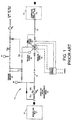
- FIG. 1 there is illustrated a gas conditioning system as described in United States Patent 6,715,985 for seal gas delivered to a non-contacting gas seal.
- the system generally designated 10, including individual components discussed below, maybe unitized as a single package on a movable skid. It may be positioned in association with an existing rotary device equipped with one or more gas lubricated non-contacting seals, or it may be part of an installation of new equipment where gas lubricated, non-contacting seals are to be used.
- connection of the system 10 to the equipment in which the seals are used may occur through suitable ports in a gas control panel shown schematically.
- gas control panels are typically located adjacent the rotary equipment being sealed and contain valves and gauges that reflect seal operation. It is contemplated that the system may be incorporated with a gas panel as a single unitized module.
- the system 10 includes a connection or inlet 12 to piping defining a conduit 15 to deliver the received process gas through the conditioning elements and to the seal chambers defined by the compressor housing.
- the inlet is connected to a source of gas for supply to the seal chamber or chamber in which there is disposed a gas lubricated, non-contacting gas seal.
- this source may typically be the discharge end of a gas compressor in which the seals are employed.
- the system 10 includes a connection or outlet 14 to piping adapted to be placed in communication with a seal chamber within the device.
- Such connection may communicate with one or more seal chambers depending on the number of seals employed in the device.
- the major conditioning elements of the system of the present invention are elements to remove solid and liquid particulate matter and aerosols from the gas, and to heat or amplify pressure of the gas when necessary.
- a knock-out filter/coalescer vessel 16 There is illustrated a knock-out filter/coalescer vessel 16, a pressure vessel 18, a gas heating element 22 and a pressure amplifier 20.
- These components are connected in fluid communication by piping or conduit, generally designated 15, that defines a flow path between the gas supply connection 12 and the connection 14 to the seal chamber.
- the knock-out filter-coalescer vessel 16 is a device that removes particulate matter and liquid droplets from the gas flowing through the system. It includes a baffle plate designated to remove solid particulate and free liquid contained in the seal gas. This separated contamination settles at the bottom of the vessel 16 and is removable, either manually, or by an automated arrangement.
- the seal gas is then further conditioned by purging it of entrapped liquid aerosols by the coalescing action of a filter element.
- the knock-out plate and coalescing filter are known devices.
- a centrifuge-type device could be employed in place of the knock-out plate. In such an arrangement, two separate vessels, one for the centrifuge, the other for the filter element, would make up the conditioning element 16.
- the pressure vessel 18 is a tank capable of maintaining gas under system pressure. Its volume is determined by the expected requirements of the seal in the seal chamber and labyrinth leakage rate. A suitable size is calculated for the particular application involved.
- the heating element 22 is disposed within pressure vessel 18.
- the compression cylinder of the gas pressure amplifier or intensifier 20 is in communication with the line 15(b) as part of the flow path to pressure vessel 18.
- the piston in the compression cylinder pressurizes the seal gas in the system for delivery to the pressure vessel 18.
- the above described system provides a liquid knockout before filtration, and insulation and heat to avoid liquid condensate formation in the buffer gas.
- this approach helps to reduce the liquid condensate, it may not be effective for emerging applications, such as ultra-high-pressure reinjection compressors, that employ heavy hydrocarbon as part of their gas compositions, and in applications where the only source of buffer gas is from the high-temperature discharge side of the compressor.
- this discharge pressure could be as high as 10,000 pounds per square inch (psi).
- the system described above may be suitable for the majority of applications. However, failures may still occur because of a lack of available clean and dry buffer gas. This is a major issue for current dry gas seal control systems and there is no warning in advance of any changes in conditions that could result in forming or exposing the dry gas seal to liquid.
- the gas analysis provided to the manufacturer to determine the dew point suitability of buffer gas and need for buffer gas conditioning is based on a limited gas analysis, typically up to Octane (C8) or less.
- the gas analysis of up to C12 may be required for manufacturer to be able to size the proper system to achieve a more suitable buffer gas and avoid liquid drop out across the sealing faces.
- buffer gas conditioning is disclosed here. It is suitable for all applications, but particularly suitable for applications, such as wet gas, or any projects where liquid or condensate may form because of operating environment changes.
- the arrangement of the present disclosure will also recognize malfunction of a gas conditioning element of the system and provide a suitable signal, alert, or automatic response.
- the monitoring and control system of the present disclosure is expected to be suitable for application to a gas compressor capable of gas discharge pressures of up to 10,000 psi or higher.
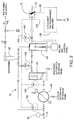
- the disclosed system commences at a pressure regulator 60 interposed between the source of process gas 12 and the gas conditioning system 10. Gas from the conditioning system 10 is delivered to the seal chambers of an associated device such as a gas compressor through conditioned gas outlet 14.
- the monitoring and control system of the present disclosure is described below. It is illustrated in relation to a typical, though not exclusive, seal gas conditioning system. In general terms, and with reference to Fig. 2 , the monitoring and control system includes one or more of the elements described below.
- a pressure regulator 60 is installed at the source 12 of process gas for supply to the seal chamber.
- the regulator is at the inlet connection 12 for the conditioning system piping or conduit 15. It receives process gas from the associated compressor for delivery through the system to the gas seal chambers. It reduces the supplied warm buffer gas pressure, which results from discharge or auxiliary gas, to a manageable and recommended sealing pressure for use in the gas seals. This is particularly critical in high- or ultra-high-pressure applications where there is a large disparity between the compressor's suction and discharge pressures. Based on gas mixture compositions, liquid condensate may form when there are changes in gas pressure and temperature. Another benefit of reducing the supplied pressure at the upstream of the system is that in ultra-high-pressure applications, the control system components do not need to be rated by the compressor's discharge pressure.
- a knockout filter 63 similar to the knockout filter 16 is installed downstream of the cooler 62. It functions as described above with reference to knockout filter 16.
- a heater 64 is added for applications whose local environments require the buffer gas temperature to be elevated to avoid liquid formation in the buffer stream. It is the equivalent to heating element 22 of Fig. 1 .
- Optional Gas Booster A gas booster or intensifier 66 may be added for applications where buffer gas may be necessary for start-up. It is the equivalent to pressure intensifier 20 of Fig. 1 .
- a liquid sensor 70 is installed adjacent the conditioning system outlet 14 to monitor the performance of the conditioning components.
- the outlet 14 leads to the seal chambers of the compressor for delivery of clean and dry seal gas upon which the non-contacting seals function.
- a liquid sensor 70 is installed at the system outlet 14 which is piped into the compressor buffer supply port.
- the sensor 70 will monitor the buffers gas condition for any sign of liquid condensate and communicate to an intelligent pre-programmed analyzer (programmable logic controller 130, Fig. 2 ) to indicate that the buffer gas contains liquid fluid.
- the programmable logic controller may initiate an output signal 140 on recognition of liquid by the sensor.
- the sensor 70 is a custom designed spectral analyzer connected to the system programmable logic controller (computer) 130 via a communication connection illustrated schematically at 80. It effectively monitors the liquid content in the target fluids. The result is a robust sensing technology with a highly variable form factor which can operate at very high temperatures and pressures.
- the sensing head is an optical evanescent wave sensor and can detect the presence of liquid in the gaseous flow based on properties of a light beam emitted and received by the sensor.
- the electronics are UL Class 1 Div 1 approved.
- the sensing head 70 can be located remotely from the electronics (programmable logic controller 130) via non-conducting fiber optic cable 80 and thus be placed in a completely non-electrified environment, thus enhancing the safety of the device.
- the programmable logic controller 130 could merely provide an audible or visual signal to alert an operator.
- the response would include initiation of a detection sequence intended to isolate the cause of the liquid presence. Such sequence would proceed employing pressure and temperature sensors 100 deployed along the conditioning path 15 as described in detail below. Any alternative combination of the monitoring devices, samplings, determinations and responses by the monitoring and control system disclosed herein is contemplated by this disclosure.
- pressure and Temperature Transmitters In the arrangement illustrated in Fig. 2 , in addition to sensor 70, pressure and temperature transmitters or sensors 100 are installed at the outlet of the treatment components, such as the pressure regulator 60, cooler 62, knockout filter 63, heater 64, and intensifier 66. These transmitters or sensors 10 are also connected by a communication path 125 to the programmable logic device 130, and provide input data for determination of the condition of the seal gas in conduit 15 as will be explained.
- a number of pressure and temperature sensing transmitters 100 are positioned along the flow path of the seal gas treatment arrangement.
- Such devices are commercially available from Honeywell Corporation and other known sources.
- a PTI device 100 is positioned downstream of each of the described treatment or conditioning devices including the pressure regulator 60, the cooler 62, the knockout filter 63, and the heater or temperature control device 64.
- the PTI devices are in communication with programmable logic device 130 (computer central processing unit (CPU)) along a communication path 125. They provide signals of the pressure and temperature of the seal gas at the various locations along the flow path of the seal gas being conditioned prior to delivery to the seal gas chambers of the non-contacting seals of the associated compressor.
- CPU computer central processing unit
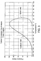
- Fig. 3 is a gas phase diagram which is illustrative of the phase of a known gas.
- the programmable logic controller 130 includes machine readable medium or memory which is provided with stored data indicative of the phase of the seal gas at various pressures and temperatures for the composition of the particular gas being processed by the associated compressor. Such stored data is inputted into the machine memory for use by the logic controller to determine the phase of the seal gas fluid flowing at the various locations of the PTI sensors.
- a phase diagram such as illustrated in Fig. 4 can be developed indicative of the phase of the fluid at various pressures and temperatures.
- the fluid is in a gaseous phase at pressures and temperatures above the dome and in a liquid phase at pressures and temperatures within the dome.
- Pre-programmed System Control Box All signals from the liquid sensor 70 and pressure and temperature transmitters 100 are connected to the programmable logic device 130 (computer or central processing unit (CPU) control box).
- the CPU identifies the seal gas fluid pressure and temperature at each location of a PTI sensor 100.
- the logic device makes a comparison to the stored data, for example the phase diagram information illustrated in Fig. 3 for a known gas representative of the process gas. In that way, the logic device determines the presence of liquid concentrate at a given PTI sensor device 100. If liquid is detected the specific signal point, a command is sent by the computer to alert the operator to remedy the condition or take action automatically to avoid dry gas seal exposure to the liquid, which is the leading cause of dry gas seal failures.
- the sensed conditions at the pressure-temperature sensing devices PTI(1), PTI(2), PTI(3), PTI(4) is compared to the phase diagram plotted as shown in Fig. 3 .
- the programmable logic controller thus recognizes the status of the gas within the system at each position of the sensors and is programmed to provide an output signal (140). It will recognize a change, including a malfunction of the associated conditioning element; such as the pressure regulator 60, cooler 62, knockout filter 63, heater 64, and intensifier 66. Any disparity between the actual reading and preset gas composition data would be indication of component malfunction or deficiency. This would allow the operator to take appropriate action before the faces are irreparably exposed to liquid fluids.
- the output signal from the programmable logic device 130 may be delivered for control purposes in any number of alternative responses. It could provide an alert, sound an alarm, or provide a printed record. In a more comprehensive system, it could cause an automatic response. Such a response could include adjustment of the functioning parameters of one, or more, of the conditioning elements of the system or in case of a need for immediate response, shut down the compressor.
- the programmable logic device may also be programmed to make the analysis of the composition of seal gas in the system and recognize deviation from the baseline data. It can then provide an output signal based on such deviation.
- An example would be in a plant process upset situation.
- the seal gas monitoring and control system of the present disclosure is intrinsically safe and provides an advanced warning if any liquid is detected in the seal gas conditioning system.
- a gas conditioning system includes an optic liquid recognition sensor to sense the presence of liquid vapor or condensate within the seal gas supply to an associated non-contacting gas seal. It is arranged with an intelligent control box to initiate an output signal.
- the monitoring system may further include pressure and temperature sensing at the output of each such device.
- Sensed data is compared to the phase diagram of the known seal gas compatibility to determine whether and when liquid is present. As a result an operator can run a diagnostic check in order to find out the reason for the presence of liquid and initiate an action item before the seal faces are exposed and adversely affected.
- the monitoring and control system further includes pressure and temperature sensors downstream of each conditioning unit or element to provide data to the central box on the condition of the seal gas flowing from the associated unit. Through comparison of the received data to stored data on the properties of the gas at various pressures and temperatures, it determines the location of the liquid concentrate. It provides an output signal to initiate appropriate remedial action.
- sensing of liquid at sensor 70 starts a detection sequence involving the PTI sensor 100 downstream of each conditioning unit.
- the sensed PTI data is received by the computer and compared to the pressure and temperature data stored in the machine readable medium indicative of the phase of the known gas composition at various pressures and temperatures.
- the need for adjustment of one or more of the conditioning units, possible process gas upset, or other anomaly may be isolated as the cause of the liquid phase and an appropriate response taken.
- the seal gas system could include conduit 15 with multiple conditioning elements such as pressure regulator 60, cooler 62, filter 63, etc., with pressure and temperature sensors 100 at the outlet of each such element, but without the sensor 70 in the conduit.
- the programmable logic controller would recognize, and respond only to temperature and pressure data from the sensors 100 and comparison to the stored data of a phase diagram ( Fig. 3 ) for the known process gas.
Landscapes
- Engineering & Computer Science (AREA)
- General Engineering & Computer Science (AREA)
- Mechanical Engineering (AREA)
- Physics & Mathematics (AREA)
- Thermal Sciences (AREA)
- Structures Of Non-Positive Displacement Pumps (AREA)
- Pipeline Systems (AREA)
- Sealing Using Fluids, Sealing Without Contact, And Removal Of Oil (AREA)
- Physical Or Chemical Processes And Apparatus (AREA)
Applications Claiming Priority (2)
| Application Number | Priority Date | Filing Date | Title |
|---|---|---|---|
| US201161514732P | 2011-08-03 | 2011-08-03 | |
| PCT/US2012/049196 WO2013019884A2 (en) | 2011-08-03 | 2012-08-01 | Seal gas monitoring and control system |
Publications (3)
| Publication Number | Publication Date |
|---|---|
| EP2742332A2 EP2742332A2 (en) | 2014-06-18 |
| EP2742332A4 EP2742332A4 (en) | 2015-08-19 |
| EP2742332B1 true EP2742332B1 (en) | 2016-09-21 |
Family
ID=47626074
Family Applications (1)
| Application Number | Title | Priority Date | Filing Date |
|---|---|---|---|
| EP12820762.8A Active EP2742332B1 (en) | 2011-08-03 | 2012-08-01 | Seal gas monitoring and control system |
Country Status (8)
Families Citing this family (38)
| Publication number | Priority date | Publication date | Assignee | Title |
|---|---|---|---|---|
| MX2010012661A (es) | 2008-05-21 | 2010-12-21 | Crane John Inc | Sistema de monitoreo y control de sello. |
| US20130233350A1 (en) * | 2012-03-07 | 2013-09-12 | Michael Tomkins | Method and system for removing hydrocarbon deposits from heat exchanger tube bundles |
| US20150322959A1 (en) * | 2012-09-06 | 2015-11-12 | Siemens Aktiengesellschaft | Turbo machine and method for the operation thereof |
| US9624785B2 (en) * | 2014-01-24 | 2017-04-18 | Solar Turbines Incorporated | System for monitoring health of a seal |
| EP2952694A1 (en) * | 2014-06-06 | 2015-12-09 | Siemens Aktiengesellschaft | Method for managing a gas turbine assembly at low speed and corresponding gas turbine assembly |
| US20160075372A1 (en) * | 2014-09-12 | 2016-03-17 | GM Global Technology Operations LLC | Early fault detection for an eps system |
| US9864823B2 (en) | 2015-03-30 | 2018-01-09 | Uop Llc | Cleansing system for a feed composition based on environmental factors |
| DE102015013659A1 (de) * | 2015-10-22 | 2017-04-27 | Man Diesel & Turbo Se | Trockengasdichtungssystem und Strömungsmaschine mit einem Trockengasdichtungssystem |
| EP4008934B1 (en) | 2016-02-23 | 2025-07-16 | John Crane UK Ltd. | System for predictive diagnostics for mechanical systems |
| CN106246582B (zh) * | 2016-07-21 | 2018-05-11 | 北京化工大学 | 旋转式压缩机异常状态自愈调控系统及方法 |
| US10545487B2 (en) | 2016-09-16 | 2020-01-28 | Uop Llc | Interactive diagnostic system and method for managing process model analysis |
| US10754359B2 (en) | 2017-03-27 | 2020-08-25 | Uop Llc | Operating slide valves in petrochemical plants or refineries |
| US10678272B2 (en) | 2017-03-27 | 2020-06-09 | Uop Llc | Early prediction and detection of slide valve sticking in petrochemical plants or refineries |
| US11130111B2 (en) | 2017-03-28 | 2021-09-28 | Uop Llc | Air-cooled heat exchangers |
| US10752844B2 (en) | 2017-03-28 | 2020-08-25 | Uop Llc | Rotating equipment in a petrochemical plant or refinery |
| US10670027B2 (en) * | 2017-03-28 | 2020-06-02 | Uop Llc | Determining quality of gas for rotating equipment in a petrochemical plant or refinery |
| US10794644B2 (en) | 2017-03-28 | 2020-10-06 | Uop Llc | Detecting and correcting thermal stresses in heat exchangers in a petrochemical plant or refinery |
| US10670353B2 (en) | 2017-03-28 | 2020-06-02 | Uop Llc | Detecting and correcting cross-leakage in heat exchangers in a petrochemical plant or refinery |
| US11396002B2 (en) | 2017-03-28 | 2022-07-26 | Uop Llc | Detecting and correcting problems in liquid lifting in heat exchangers |
| US11037376B2 (en) | 2017-03-28 | 2021-06-15 | Uop Llc | Sensor location for rotating equipment in a petrochemical plant or refinery |
| US10844290B2 (en) | 2017-03-28 | 2020-11-24 | Uop Llc | Rotating equipment in a petrochemical plant or refinery |
| US10962302B2 (en) | 2017-03-28 | 2021-03-30 | Uop Llc | Heat exchangers in a petrochemical plant or refinery |
| US10752845B2 (en) | 2017-03-28 | 2020-08-25 | Uop Llc | Using molecular weight and invariant mapping to determine performance of rotating equipment in a petrochemical plant or refinery |
| US10663238B2 (en) | 2017-03-28 | 2020-05-26 | Uop Llc | Detecting and correcting maldistribution in heat exchangers in a petrochemical plant or refinery |
| US10695711B2 (en) | 2017-04-28 | 2020-06-30 | Uop Llc | Remote monitoring of adsorber process units |
| US11365886B2 (en) | 2017-06-19 | 2022-06-21 | Uop Llc | Remote monitoring of fired heaters |
| US10913905B2 (en) | 2017-06-19 | 2021-02-09 | Uop Llc | Catalyst cycle length prediction using eigen analysis |
| US10739798B2 (en) | 2017-06-20 | 2020-08-11 | Uop Llc | Incipient temperature excursion mitigation and control |
| EP3418502A1 (de) * | 2017-06-20 | 2018-12-26 | Siemens Aktiengesellschaft | Verfahren zur überprüfung einer strömungsmaschine |
| US11130692B2 (en) | 2017-06-28 | 2021-09-28 | Uop Llc | Process and apparatus for dosing nutrients to a bioreactor |
| US11194317B2 (en) | 2017-10-02 | 2021-12-07 | Uop Llc | Remote monitoring of chloride treaters using a process simulator based chloride distribution estimate |
| US11105787B2 (en) | 2017-10-20 | 2021-08-31 | Honeywell International Inc. | System and method to optimize crude oil distillation or other processing by inline analysis of crude oil properties |
| US10901403B2 (en) | 2018-02-20 | 2021-01-26 | Uop Llc | Developing linear process models using reactor kinetic equations |
| US10734098B2 (en) | 2018-03-30 | 2020-08-04 | Uop Llc | Catalytic dehydrogenation catalyst health index |
| US10953377B2 (en) | 2018-12-10 | 2021-03-23 | Uop Llc | Delta temperature control of catalytic dehydrogenation process reactors |
| JP7222833B2 (ja) * | 2019-07-03 | 2023-02-15 | 株式会社神戸製鋼所 | 圧縮機及び圧縮機におけるシールガスの調整方法 |
| CN111256920B (zh) * | 2020-01-17 | 2022-03-15 | 中密控股股份有限公司 | 干气密封智能监测系统 |
| CN114166945B (zh) * | 2022-02-14 | 2022-04-12 | 烟台锐铭金属材料有限公司 | 锅炉压力容器检验检测装置 |
Family Cites Families (16)
| Publication number | Priority date | Publication date | Assignee | Title |
|---|---|---|---|---|
| US700013A (en) * | 1902-02-15 | 1902-05-13 | Jules Leon Vimont | Shirt-band stiffener. |
| US5291032A (en) * | 1991-08-21 | 1994-03-01 | Hughes Aircraft Company | Fiber optic evanescent wave fuel gauge and leak detector using eccentric core fibers |
| CH686525A5 (de) * | 1992-07-02 | 1996-04-15 | Escher Wyss Ag | Turbomaschine . |
| US5375853B1 (en) * | 1992-09-18 | 1998-05-05 | Crane John Inc | Gas lubricated barrier seal |
| AU1192897A (en) | 1995-06-23 | 1997-01-22 | Revolve Technologies Inc. | Dry seal contamination prevention system |
| US5700013A (en) * | 1997-01-22 | 1997-12-23 | John Crane Inc. | Secondary seal with mechanical gas seal |
| US6626436B2 (en) * | 1997-08-20 | 2003-09-30 | Crane John Inc | Monitoring seal system |
| EP1207310B1 (en) * | 1999-07-23 | 2011-04-20 | Hitachi Plant Technologies, Ltd. | Dry gas seal for turbo fluid machinery |
| US6394764B1 (en) * | 2000-03-30 | 2002-05-28 | Dresser-Rand Company | Gas compression system and method utilizing gas seal control |
| JP3500355B2 (ja) * | 2000-11-17 | 2004-02-23 | 株式会社日立製作所 | 遠心圧縮機の軸封システム |
| US6715985B2 (en) * | 2002-05-15 | 2004-04-06 | John Crane Inc. | Gas conditioning system |
| EP1577561A1 (de) * | 2004-03-19 | 2005-09-21 | MAN Turbomaschinen AG Schweiz | Umwälz- und Heizvorrichtung für einen Rotationskompressor |
| GB0425516D0 (en) * | 2004-11-19 | 2004-12-22 | Evanesco Ltd | Methods and apparatus for optical monitoring of fluid level and quality |
| US7854584B2 (en) * | 2007-05-24 | 2010-12-21 | General Electric Company | Barrier sealing system for centrifugal compressors |
| MX2010012661A (es) * | 2008-05-21 | 2010-12-21 | Crane John Inc | Sistema de monitoreo y control de sello. |
| JP5535749B2 (ja) * | 2010-04-28 | 2014-07-02 | 三菱重工業株式会社 | ドライガスシール構造 |
-
2012
- 2012-08-01 WO PCT/US2012/049196 patent/WO2013019884A2/en active Application Filing
- 2012-08-01 US US13/564,374 patent/US9145783B2/en active Active
- 2012-08-01 MX MX2014001130A patent/MX2014001130A/es active IP Right Grant
- 2012-08-01 JP JP2014524053A patent/JP6126596B2/ja active Active
- 2012-08-01 CA CA2843799A patent/CA2843799A1/en active Pending
- 2012-08-01 BR BR112014002536-3A patent/BR112014002536B1/pt active IP Right Grant
- 2012-08-01 EP EP12820762.8A patent/EP2742332B1/en active Active
- 2012-08-01 AU AU2012290099A patent/AU2012290099B2/en active Active
Also Published As
| Publication number | Publication date |
|---|---|
| CA2843799A1 (en) | 2013-02-07 |
| EP2742332A2 (en) | 2014-06-18 |
| WO2013019884A3 (en) | 2014-05-08 |
| AU2012290099A1 (en) | 2014-02-20 |
| US20130031960A1 (en) | 2013-02-07 |
| AU2012290099B2 (en) | 2015-11-12 |
| JP2014529709A (ja) | 2014-11-13 |
| BR112014002536B1 (pt) | 2021-05-18 |
| JP6126596B2 (ja) | 2017-05-10 |
| US9145783B2 (en) | 2015-09-29 |
| EP2742332A4 (en) | 2015-08-19 |
| MX2014001130A (es) | 2014-02-27 |
| WO2013019884A2 (en) | 2013-02-07 |
| BR112014002536A2 (pt) | 2017-03-14 |
Similar Documents
| Publication | Publication Date | Title |
|---|---|---|
| EP2742332B1 (en) | Seal gas monitoring and control system | |
| JP5285147B2 (ja) | シール監視及び制御システム | |
| US6524059B1 (en) | Turbo fluid machinery and dry gas seal used for the machinery | |
| US20020197154A1 (en) | Turbo type fluid machine and dry gas seal for use therefor | |
| CA2870918C (en) | Furnace combustion cross limit control with real-time diagnostic features | |
| US10900880B2 (en) | Cabin air control system for an aircraft | |
| US6715985B2 (en) | Gas conditioning system | |
| WO2009029420A1 (en) | Control method for gas compression | |
| WO2013050746A1 (en) | A well fluid heat exchange system, a control assembly and method thereof | |
| US7343781B2 (en) | Systems and methods for detecting liquid particles in a gas system | |
| US20160053905A1 (en) | Refrigerant Relief Valve Monitoring System and Method | |
| Schmidt et al. | Monitoring a Tandem Dry Gas Seal's Secondary Seal | |
| Lauriola | Oil & Gas University-2018 Resident Course | |
| AU2014240372A1 (en) | Seal monitoring and control system |
Legal Events
| Date | Code | Title | Description |
|---|---|---|---|
| PUAI | Public reference made under article 153(3) epc to a published international application that has entered the european phase |
Free format text: ORIGINAL CODE: 0009012 |
|
| 17P | Request for examination filed |
Effective date: 20140204 |
|
| AK | Designated contracting states |
Kind code of ref document: A2 Designated state(s): AL AT BE BG CH CY CZ DE DK EE ES FI FR GB GR HR HU IE IS IT LI LT LU LV MC MK MT NL NO PL PT RO RS SE SI SK SM TR |
|
| DAX | Request for extension of the european patent (deleted) | ||
| A4 | Supplementary search report drawn up and despatched |
Effective date: 20150717 |
|
| RIC1 | Information provided on ipc code assigned before grant |
Ipc: F01D 11/00 20060101ALI20150713BHEP Ipc: F25B 49/00 20060101ALI20150713BHEP Ipc: F16J 15/34 20060101ALI20150713BHEP Ipc: F01D 11/06 20060101ALI20150713BHEP Ipc: G01M 3/14 20060101AFI20150713BHEP |
|
| GRAP | Despatch of communication of intention to grant a patent |
Free format text: ORIGINAL CODE: EPIDOSNIGR1 |
|
| INTG | Intention to grant announced |
Effective date: 20160421 |
|
| GRAS | Grant fee paid |
Free format text: ORIGINAL CODE: EPIDOSNIGR3 |
|
| GRAA | (expected) grant |
Free format text: ORIGINAL CODE: 0009210 |
|
| AK | Designated contracting states |
Kind code of ref document: B1 Designated state(s): AL AT BE BG CH CY CZ DE DK EE ES FI FR GB GR HR HU IE IS IT LI LT LU LV MC MK MT NL NO PL PT RO RS SE SI SK SM TR |
|
| REG | Reference to a national code |
Ref country code: GB Ref legal event code: FG4D |
|
| REG | Reference to a national code |
Ref country code: CH Ref legal event code: EP |
|
| REG | Reference to a national code |
Ref country code: AT Ref legal event code: REF Ref document number: 831435 Country of ref document: AT Kind code of ref document: T Effective date: 20161015 |
|
| REG | Reference to a national code |
Ref country code: IE Ref legal event code: FG4D |
|
| REG | Reference to a national code |
Ref country code: DE Ref legal event code: R096 Ref document number: 602012023365 Country of ref document: DE |
|
| REG | Reference to a national code |
Ref country code: LT Ref legal event code: MG4D Ref country code: NL Ref legal event code: MP Effective date: 20160921 |
|
| PG25 | Lapsed in a contracting state [announced via postgrant information from national office to epo] |
Ref country code: RS Free format text: LAPSE BECAUSE OF FAILURE TO SUBMIT A TRANSLATION OF THE DESCRIPTION OR TO PAY THE FEE WITHIN THE PRESCRIBED TIME-LIMIT Effective date: 20160921 Ref country code: HR Free format text: LAPSE BECAUSE OF FAILURE TO SUBMIT A TRANSLATION OF THE DESCRIPTION OR TO PAY THE FEE WITHIN THE PRESCRIBED TIME-LIMIT Effective date: 20160921 Ref country code: NO Free format text: LAPSE BECAUSE OF FAILURE TO SUBMIT A TRANSLATION OF THE DESCRIPTION OR TO PAY THE FEE WITHIN THE PRESCRIBED TIME-LIMIT Effective date: 20161221 Ref country code: FI Free format text: LAPSE BECAUSE OF FAILURE TO SUBMIT A TRANSLATION OF THE DESCRIPTION OR TO PAY THE FEE WITHIN THE PRESCRIBED TIME-LIMIT Effective date: 20160921 Ref country code: LT Free format text: LAPSE BECAUSE OF FAILURE TO SUBMIT A TRANSLATION OF THE DESCRIPTION OR TO PAY THE FEE WITHIN THE PRESCRIBED TIME-LIMIT Effective date: 20160921 |
|
| REG | Reference to a national code |
Ref country code: AT Ref legal event code: MK05 Ref document number: 831435 Country of ref document: AT Kind code of ref document: T Effective date: 20160921 |
|
| PG25 | Lapsed in a contracting state [announced via postgrant information from national office to epo] |
Ref country code: NL Free format text: LAPSE BECAUSE OF FAILURE TO SUBMIT A TRANSLATION OF THE DESCRIPTION OR TO PAY THE FEE WITHIN THE PRESCRIBED TIME-LIMIT Effective date: 20160921 Ref country code: SE Free format text: LAPSE BECAUSE OF FAILURE TO SUBMIT A TRANSLATION OF THE DESCRIPTION OR TO PAY THE FEE WITHIN THE PRESCRIBED TIME-LIMIT Effective date: 20160921 Ref country code: GR Free format text: LAPSE BECAUSE OF FAILURE TO SUBMIT A TRANSLATION OF THE DESCRIPTION OR TO PAY THE FEE WITHIN THE PRESCRIBED TIME-LIMIT Effective date: 20161222 Ref country code: LV Free format text: LAPSE BECAUSE OF FAILURE TO SUBMIT A TRANSLATION OF THE DESCRIPTION OR TO PAY THE FEE WITHIN THE PRESCRIBED TIME-LIMIT Effective date: 20160921 |
|
| PG25 | Lapsed in a contracting state [announced via postgrant information from national office to epo] |
Ref country code: RO Free format text: LAPSE BECAUSE OF FAILURE TO SUBMIT A TRANSLATION OF THE DESCRIPTION OR TO PAY THE FEE WITHIN THE PRESCRIBED TIME-LIMIT Effective date: 20160921 Ref country code: EE Free format text: LAPSE BECAUSE OF FAILURE TO SUBMIT A TRANSLATION OF THE DESCRIPTION OR TO PAY THE FEE WITHIN THE PRESCRIBED TIME-LIMIT Effective date: 20160921 |
|
| PG25 | Lapsed in a contracting state [announced via postgrant information from national office to epo] |
Ref country code: AT Free format text: LAPSE BECAUSE OF FAILURE TO SUBMIT A TRANSLATION OF THE DESCRIPTION OR TO PAY THE FEE WITHIN THE PRESCRIBED TIME-LIMIT Effective date: 20160921 Ref country code: SM Free format text: LAPSE BECAUSE OF FAILURE TO SUBMIT A TRANSLATION OF THE DESCRIPTION OR TO PAY THE FEE WITHIN THE PRESCRIBED TIME-LIMIT Effective date: 20160921 Ref country code: SK Free format text: LAPSE BECAUSE OF FAILURE TO SUBMIT A TRANSLATION OF THE DESCRIPTION OR TO PAY THE FEE WITHIN THE PRESCRIBED TIME-LIMIT Effective date: 20160921 Ref country code: BE Free format text: LAPSE BECAUSE OF FAILURE TO SUBMIT A TRANSLATION OF THE DESCRIPTION OR TO PAY THE FEE WITHIN THE PRESCRIBED TIME-LIMIT Effective date: 20160921 Ref country code: BG Free format text: LAPSE BECAUSE OF FAILURE TO SUBMIT A TRANSLATION OF THE DESCRIPTION OR TO PAY THE FEE WITHIN THE PRESCRIBED TIME-LIMIT Effective date: 20161221 Ref country code: ES Free format text: LAPSE BECAUSE OF FAILURE TO SUBMIT A TRANSLATION OF THE DESCRIPTION OR TO PAY THE FEE WITHIN THE PRESCRIBED TIME-LIMIT Effective date: 20160921 Ref country code: IS Free format text: LAPSE BECAUSE OF FAILURE TO SUBMIT A TRANSLATION OF THE DESCRIPTION OR TO PAY THE FEE WITHIN THE PRESCRIBED TIME-LIMIT Effective date: 20170121 Ref country code: CZ Free format text: LAPSE BECAUSE OF FAILURE TO SUBMIT A TRANSLATION OF THE DESCRIPTION OR TO PAY THE FEE WITHIN THE PRESCRIBED TIME-LIMIT Effective date: 20160921 Ref country code: PT Free format text: LAPSE BECAUSE OF FAILURE TO SUBMIT A TRANSLATION OF THE DESCRIPTION OR TO PAY THE FEE WITHIN THE PRESCRIBED TIME-LIMIT Effective date: 20170123 Ref country code: PL Free format text: LAPSE BECAUSE OF FAILURE TO SUBMIT A TRANSLATION OF THE DESCRIPTION OR TO PAY THE FEE WITHIN THE PRESCRIBED TIME-LIMIT Effective date: 20160921 |
|
| REG | Reference to a national code |
Ref country code: DE Ref legal event code: R097 Ref document number: 602012023365 Country of ref document: DE |
|
| PLBE | No opposition filed within time limit |
Free format text: ORIGINAL CODE: 0009261 |
|
| STAA | Information on the status of an ep patent application or granted ep patent |
Free format text: STATUS: NO OPPOSITION FILED WITHIN TIME LIMIT |
|
| PG25 | Lapsed in a contracting state [announced via postgrant information from national office to epo] |
Ref country code: DK Free format text: LAPSE BECAUSE OF FAILURE TO SUBMIT A TRANSLATION OF THE DESCRIPTION OR TO PAY THE FEE WITHIN THE PRESCRIBED TIME-LIMIT Effective date: 20160921 |
|
| 26N | No opposition filed |
Effective date: 20170622 |
|
| PG25 | Lapsed in a contracting state [announced via postgrant information from national office to epo] |
Ref country code: SI Free format text: LAPSE BECAUSE OF FAILURE TO SUBMIT A TRANSLATION OF THE DESCRIPTION OR TO PAY THE FEE WITHIN THE PRESCRIBED TIME-LIMIT Effective date: 20160921 |
|
| REG | Reference to a national code |
Ref country code: CH Ref legal event code: PL |
|
| PG25 | Lapsed in a contracting state [announced via postgrant information from national office to epo] |
Ref country code: MC Free format text: LAPSE BECAUSE OF FAILURE TO SUBMIT A TRANSLATION OF THE DESCRIPTION OR TO PAY THE FEE WITHIN THE PRESCRIBED TIME-LIMIT Effective date: 20160921 |
|
| PG25 | Lapsed in a contracting state [announced via postgrant information from national office to epo] |
Ref country code: CH Free format text: LAPSE BECAUSE OF NON-PAYMENT OF DUE FEES Effective date: 20170831 Ref country code: LI Free format text: LAPSE BECAUSE OF NON-PAYMENT OF DUE FEES Effective date: 20170831 |
|
| REG | Reference to a national code |
Ref country code: FR Ref legal event code: ST Effective date: 20180430 |
|
| REG | Reference to a national code |
Ref country code: IE Ref legal event code: MM4A |
|
| PG25 | Lapsed in a contracting state [announced via postgrant information from national office to epo] |
Ref country code: LU Free format text: LAPSE BECAUSE OF NON-PAYMENT OF DUE FEES Effective date: 20170801 |
|
| PG25 | Lapsed in a contracting state [announced via postgrant information from national office to epo] |
Ref country code: IE Free format text: LAPSE BECAUSE OF NON-PAYMENT OF DUE FEES Effective date: 20170801 |
|
| PG25 | Lapsed in a contracting state [announced via postgrant information from national office to epo] |
Ref country code: FR Free format text: LAPSE BECAUSE OF NON-PAYMENT OF DUE FEES Effective date: 20170831 |
|
| PG25 | Lapsed in a contracting state [announced via postgrant information from national office to epo] |
Ref country code: MT Free format text: LAPSE BECAUSE OF NON-PAYMENT OF DUE FEES Effective date: 20170801 |
|
| PG25 | Lapsed in a contracting state [announced via postgrant information from national office to epo] |
Ref country code: AL Free format text: LAPSE BECAUSE OF FAILURE TO SUBMIT A TRANSLATION OF THE DESCRIPTION OR TO PAY THE FEE WITHIN THE PRESCRIBED TIME-LIMIT Effective date: 20160921 |
|
| PG25 | Lapsed in a contracting state [announced via postgrant information from national office to epo] |
Ref country code: HU Free format text: LAPSE BECAUSE OF FAILURE TO SUBMIT A TRANSLATION OF THE DESCRIPTION OR TO PAY THE FEE WITHIN THE PRESCRIBED TIME-LIMIT; INVALID AB INITIO Effective date: 20120801 |
|
| PG25 | Lapsed in a contracting state [announced via postgrant information from national office to epo] |
Ref country code: CY Free format text: LAPSE BECAUSE OF NON-PAYMENT OF DUE FEES Effective date: 20160921 |
|
| PG25 | Lapsed in a contracting state [announced via postgrant information from national office to epo] |
Ref country code: MK Free format text: LAPSE BECAUSE OF FAILURE TO SUBMIT A TRANSLATION OF THE DESCRIPTION OR TO PAY THE FEE WITHIN THE PRESCRIBED TIME-LIMIT Effective date: 20160921 |
|
| PG25 | Lapsed in a contracting state [announced via postgrant information from national office to epo] |
Ref country code: TR Free format text: LAPSE BECAUSE OF FAILURE TO SUBMIT A TRANSLATION OF THE DESCRIPTION OR TO PAY THE FEE WITHIN THE PRESCRIBED TIME-LIMIT Effective date: 20160921 |
|
| P01 | Opt-out of the competence of the unified patent court (upc) registered |
Effective date: 20230522 |
|
| PGFP | Annual fee paid to national office [announced via postgrant information from national office to epo] |
Ref country code: DE Payment date: 20240604 Year of fee payment: 13 |
|
| PGFP | Annual fee paid to national office [announced via postgrant information from national office to epo] |
Ref country code: IT Payment date: 20240710 Year of fee payment: 13 |
|
| PGFP | Annual fee paid to national office [announced via postgrant information from national office to epo] |
Ref country code: GB Payment date: 20250612 Year of fee payment: 14 |