EP2741271A1 - Object detector and object detection method - Google Patents
Object detector and object detection method Download PDFInfo
- Publication number
- EP2741271A1 EP2741271A1 EP12819626.8A EP12819626A EP2741271A1 EP 2741271 A1 EP2741271 A1 EP 2741271A1 EP 12819626 A EP12819626 A EP 12819626A EP 2741271 A1 EP2741271 A1 EP 2741271A1
- Authority
- EP
- European Patent Office
- Prior art keywords
- vehicle
- solid object
- detection
- traffic lane
- region
- Prior art date
- Legal status (The legal status is an assumption and is not a legal conclusion. Google has not performed a legal analysis and makes no representation as to the accuracy of the status listed.)
- Granted
Links
Images













Classifications
-
- G—PHYSICS
- G06—COMPUTING OR CALCULATING; COUNTING
- G06V—IMAGE OR VIDEO RECOGNITION OR UNDERSTANDING
- G06V20/00—Scenes; Scene-specific elements
- G06V20/50—Context or environment of the image
- G06V20/56—Context or environment of the image exterior to a vehicle by using sensors mounted on the vehicle
- G06V20/58—Recognition of moving objects or obstacles, e.g. vehicles or pedestrians; Recognition of traffic objects, e.g. traffic signs, traffic lights or roads
-
- G—PHYSICS
- G08—SIGNALLING
- G08G—TRAFFIC CONTROL SYSTEMS
- G08G1/00—Traffic control systems for road vehicles
- G08G1/16—Anti-collision systems
- G08G1/167—Driving aids for lane monitoring, lane changing, e.g. blind spot detection
-
- G—PHYSICS
- G06—COMPUTING OR CALCULATING; COUNTING
- G06V—IMAGE OR VIDEO RECOGNITION OR UNDERSTANDING
- G06V2201/00—Indexing scheme relating to image or video recognition or understanding
- G06V2201/08—Detecting or categorising vehicles
Definitions
- the present invention relates to a solid object detection device and a solid object detection method.
- the detection region includes a location that is a blind spot of at least a side mirror, and when the angle of the side mirror changes, the position of the detection region is changed accordingly (see Patent Document 1).
- Patent Document 1 Japanese Laid-Open Patent Publication No. 2000-149197
- the detection region is fixed as long as the angle of the side mirror does not change. In such a state, in cases such as when the vehicle nears the left side of the traffic lane and the other vehicle or the like in the right adjacent traffic lane is near the right side of the first traffic lane, for example, the other vehicle does not enter the detection region and the solid object can no longer be detected.
- the present invention was devised in order to solve such problems in the prior art, it being an object of the invention to provide a solid object detection device and a solid object detection method whereby the precision of detecting solid objects can be improved.
- the solid object detection device of the present invention captures an image including a dividing line and a predetermined region of an adjacent traffic lane, and assesses whether or not there is a solid object in the predetermined region. From the captured image, the solid object detection device detects a vehicle-widthwise distance between the vehicle position and the dividing line in the traffic lane traveled by the vehicle, and the size of the predetermined region positioned on the side where the dividing line is located increases farther outward in the vehicle-width direction in correspondence with a greater the vehicle-widthwise distance.
- the predetermined region in which the vehicle-widthwise distance is positioned on the side where the dividing line is located is enlarged farther outward in the vehicle-width direction correspondingly with respect to an increase in the vehicle-widthwise distance between the vehicle position and the dividing line. Therefore, it is possible to avoid situations in which due to the vehicle being separated from the dividing line, for example, the predetermined region is not set appropriate to the adjacent vehicle, and a solid object such as another vehicle is outside of the predetermined region and fails to be detected. Therefore, the precision of detecting solid objects can be improved.
- FIG. 1 is a schematic diagram of the solid object detection device 1 according to the present embodiment, showing an example of a case in which the solid object detection device 1 is installed in a vehicle V.
- the solid object detection device 1 shown in FIG. 1 detects solid objects (e.g. other vehicles, two-wheeled vehicles, etc.) traveling in an adjacent traffic lane that is adjacent to the traveled lane on which the vehicle V is traveling, the adjacent traffic lane being adjacent across a dividing line as a border; the solid object detection device 1 provides various information to the driver of the vehicle V; and the solid object detection device 1 comprises a camera (image-capturing means) 10, a vehicle speed sensor 20, and a computer 30.
- solid objects e.g. other vehicles, two-wheeled vehicles, etc.
- travelling lane refers to a travel band on which the vehicle V can travel when there are no lane changes, which is also a region that excludes the dividing line.
- adjacent traffic lane refers to a travel band adjacent to the traveled lane across the dividing line, which is also a region that excludes the dividing line.
- the dividing line is a line such as the white lines or the like that serve as the border between the traveled lane and the adjacent traffic lane.
- the camera 10 shown in FIG. 1 is attached so at a location at a height h in the rear of the vehicle V, an optical axis is at an angle ⁇ downward from horizontal.
- the camera 10 is designed to take images of the detection region from this position.
- the vehicle speed sensor 20 detects the traveling speed of the vehicle V, for which a sensor or the like for sensing the rotating speed of the wheels, for example, is applied.
- the computer 30 Based on the images captured by the camera 10, the computer 30 detects solid objects (e.g. other vehicles, two-wheeled vehicles, etc.) located to the rear of the vehicle V.
- the solid object detection device 1 also has a warning device (not shown), and issues warnings to the driver of the vehicle V in cases such as when there is a possibility of a shifting operation detected by the computer 30 coming in contact with the vehicle V.
- FIG. 2 is an bird's-eye view view showing the traveling state of the vehicle V shown in FIG. 1 .
- the camera 10 is capable of image-capturing a region to the rear of the vehicle V, or specifically a region including the dividing line and the adjacent traffic lane, as shown in FIG. 2 .
- Detection regions (predetermined areas) A1, A2 for detecting solid objects such as other vehicles are set in adjacent traffic lanes that are adjacent to the traveled lane in which the vehicle V is traveling, and the computer 30 detects whether or not there are solid objects in the detection regions A1, A2.
- Such detection regions A1, A2 are set from their relative positions with respect to the vehicle V.
- FIG. 3 is a block diagram showing the details of the computer 30 shown in FIG. 1 .
- the camera 10 and the vehicle speed sensor 20 are also shown in order to give a clear depiction of the relationship of connection.
- the computer 30 comprises a viewpoint conversion unit 31, a positional alignment unit (positional alignment means) 32, and a solid object detection unit (solid object detection means) 33, as shown in FIG. 3 .
- the viewpoint conversion unit 31 inputs captured image data including the detection regions A1, A2 obtained by the image-capturing performed by the camera 10, and converts the viewpoint of the inputted captured image data into bird's-eye view image data which is seen as viewed from bird's-eye view.
- This bird's-eye view view is what would be seen from the viewpoint of an imaginary camera looking vertically downward, for example, from the air above.
- This viewpoint conversion is performed as is disclosed in Japanese Laid-Open Patent Publication No. 2008-219063 , for example.
- the positional alignment unit 32 sequentially inputs the bird's-eye view image data obtained by the viewpoint conversion of the viewpoint conversion unit 31, and matches the position of inputted bird's-eye view image data of a different time.
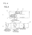
- FIG. 4 is a top view showing an outline of the process of the positional alignment unit 32 shown in FIG. 3 , wherein (a) shows the movement state of the vehicle V and (b) shows an outline of positional alignment.
- the vehicle V of the current time is positioned at V1, and the vehicle V at one time prior is positioned at V2.
- Another vehicle V is traveling parallel to the vehicle V in a position to the rear of the vehicle V, the other vehicle V of the current time is positioned at V3, and the other vehicle V of one time prior is positioned at V4.
- the vehicle V moves a distance d in one time.
- the term "one time prior" may refer to a time in the past from the current time by a time duration established in advance (e.g. one control cycle), or it may refer to a time in the past by any desired time duration.
- the bird's-eye view image PB t at the current time is shown in FIG. 4(b) .
- the white lines painted on the road are rectangular and are in a state of being seen from above comparatively accurately.
- the other vehicle V3 is beginning to fall into the image.
- the white lines painted on the road are rectangular and are in a state of being seen from above comparatively accurately, but the other vehicle V4 is beginning to fall into the image.
- the positional alignment unit 32 implements the positional alignment of the bird's-eye view images PB t , PB t-1 described above in terms of data. At this time, the positional alignment unit 32 offsets the bird's-eye view image PB t-1 at the one time prior, and causes the position to coincide with the bird's-eye view image PB t at the current time.
- the offset amount d' is merely an amount corresponding to the travel distance d shown in FIG. 4(a) , and is determined based on a signal from the vehicle speed sensor 20 and on the time duration from the one time prior to the current time.
- the positional alignment unit 32 finds the differential between the bird's-eye view images PB t , PB t-1 , and generates data of a differential image PD t .
- the pixel value of the differential image PD t may be the absolute value of the difference in pixel values between the bird's-eye view images PB t , PB t-1 , or, in order to correspond with changes in the illuminated environment, it may be "1" when the absolute value exceeds a predetermined value and "0" when the absolute value does not exceed a predetermined value.
- FIG. 3 is again referenced.
- the computer 30 comprises a lateral position detection unit (lateral position detection means) 34.
- the lateral position detection unit 34 Based on the captured image data captured by the camera 10, the lateral position detection unit 34 detects the vehicle position (specifically the side surface of the vehicle V) in the traffic lane traveled by the vehicle V, and the vehicle-widthwise distance to the dividing line that divides the traffic lane.
- the lateral position detection unit 34 makes it possible for the computer 30 to detect things such as whether the vehicle is traveling through the center of the traveled lane or traveling nearer toward either the left or right side.
- the solid object detection unit 33 detects solid objects based on the data of the differential image PD t such as is shown in FIG. 4 .
- the solid object detection unit 33 comprises a differential waveform generation unit (differential waveform generation means) 33a and a region setting unit (region setting means) 33b.
- FIG. 5 is a schematic diagram showing the manner in which differential waveforms are generated by the differential waveform generation unit 33a shown in FIG. 3 .
- the differential waveform generation unit 33a generates a differential waveform DW t from the portions in the differential image PD t that are equivalent to the detection regions A1, A2, as shown in FIG. 5 .
- the differential waveform generation unit 33a generates a differential waveform DW t along the direction in which the solid object falls by viewpoint conversion.
- the description uses only the detection region A1 for the sake of convenience.
- the differential waveform generation unit 33a defines a line La along the direction in which the solid object falls in the data of the differential waveform DW t .
- the differential waveform generation unit 33a then counts the number of differential pixels DP representing predetermined differentials along the line La.
- the differential pixels DP representing predetermined differentials herein are pixels exceeding a predetermined value when the pixel value of the differential waveform DW t is the absolute value of the difference between the pixel values of the bird's-eye view images PB t , PB t-1 , and the differential pixels DP are pixels representing "1" when the pixel value of the differential waveform DW t is expressed as "0" "1.”
- the differential waveform generation unit 33a After counting the number of differential pixels DP, the differential waveform generation unit 33a finds an intersection point CP of the line La and a line L1. The differential waveform generation unit 33a correlates the intersection point CP and the counted number, determines the horizontal axis position (a position on the up-down axis on the image plane of FIG. 5 ), and determines the vertical axis position (a position on the left-right axis on the image plane of FIG. 5 ) from the counted number.
- the differential waveform generation unit 33a continues to similarly define a line along the direction in which the solid object falls, count the number of differential pixels DP, determine the horizontal axis position based on the position of the intersection point CP, and determine the vertical axis position from the counted number (the number of differential pixels DP).
- the solid object detection unit 33 generates a differential waveform DW by sequentially repeating the above process and creating a frequency distribution.
- the lines La and Lb in the falling direction of the solid object overlap the detection region A1 in different distances. Therefore, assuming the detection region A1 is filled with differential pixels DP, the line La has more differential pixels DP than the line Lb. Therefore, when determining the vertical axis position from the counted number of differential pixels DP, the differential waveform generation unit 33a normalizes the vertical axis position based on the distance whereby the lines La, Lb in the falling direction of the solid object and the detection region A1 overlap. To give a specific example, there are six differential pixels DP on the line La in FIG. 5 , and there are five differential pixels DP on the line Lb. Therefore, when determining the vertical axis position from the counted number in FIG.
- the differential waveform generation unit 33a normalizes the vertical axis position by a method such as dividing the counted number by the overlap distance.
- the values of the differential waveform DW t that correspond to the lines La, Lb in the falling direction of the solid object are thereby substantially equal, as shown in the differential waveform DW t .
- the solid object detection unit 33 detects the solid object based on the data of the differential waveform DW t .
- the lateral position detection unit 34 first calculates an estimated speed of the solid object by correlating the differential waveform DW t-1 of one time prior and the current differential waveform DW t .
- the differential waveform DW is likely to have two local maximum values because differential pixels DP are easily obtained in the tire portions of the other vehicle V.
- the relative speed of the other vehicle V in relation to the vehicle V can be found by finding the discrepancy between the local maximum values of the differential waveform DW t- of one time prior and the current differential waveform DW t .
- the lateral position detection unit 34 thereby finds the estimated speed of the solid object.
- the lateral position detection unit 34 assesses whether or not the solid object is a solid object by assessing if the estimated speed of the solid object is an appropriate speed for a solid object.
- the region setting unit 33b sets the sizes of the detection regions A1, A2 shown in FIG. 2 .
- FIG. 6 is a top view showing the traveling state of the vehicle shown in FIG. 1 , and showing an example of a case in which the vehicle V is traveling off-center in the travel lane. As shown in FIG. 6 , the vehicle V is traveling off-center in the travel lane, and is traveling near the dividing line on the left side of the vehicle (the left side from the driver's view point).
- the region setting unit 33b enlarges the detection region A1 to prevent situations that would cause detection failures.
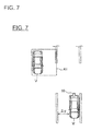
- FIG. 7 is a top view showing the traveling state of the vehicle shown in FIG. 1 , and showing an example of a case in which the region setting unit 33b has enlarged the detection region A1.
- the detection region A1 is enlarged by the region setting unit 33b as shown in FIG. 7 .
- the other vehicle V thereby comes to be positioned inside the detection region A1, and failures to detect the other vehicle V can be prevented.
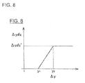
- FIG. 8 is a graph showing the relationship between the vehicle-widthwise distance ⁇ y to the dividing line and the size of the detection region ⁇ 1 (the enlarged amount ⁇ y 0 fs).
- the enlarged amount of the detection region A1 is zero.
- the enlarged amount of the detection region A1 increases according to the size of the vehicle-widthwise distance ⁇ y. Furthermore, when the vehicle-widthwise distance ⁇ y exceeds y2, the enlarged amount of the detection region A1 is fixed at y 0 fs'.
- the reason the enlarged amount of the detection region A1 is fixed at the specific value of y 0 fs' is because when the detection region A1 is enlarged limitlessly, there is a possibility that the detection region A1 will encompass not only the adjacent traffic lane subsequent lanes as well.
- the enlarged amount of the detection region A1 comparatively increases in the interval of the vehicle-widthwise distance ⁇ y between y1 and y2, but this increasing is not particularly limited to a proportional increase, and may be an exponential increase or the like. As is clear from FIG. 8 , when the vehicle-widthwise distance ⁇ y to the dividing line is short, the detection region A1 that had been enlarged is then contracted.
- the detection region A1 is enlarged based on the vehicle-widthwise distance ⁇ y from the vehicle's right side surface (the right side surface from the driver's view point) to the dividing line on the right side, but when the size of the detection region A2 is varied, needless to say, the detection region is decided based on the vehicle-widthwise distance ⁇ y from the vehicle's left side surface (the left side surface from the driver's view point) to the dividing line on the left side.
- the region setting unit 33b is configured to not severely vary the detection regions A1, A2. This is because when the detection regions A1, A2 are varied severely, the solid object detection becomes unstable, and there is a possibility that it will lead to solid object detection failures.
- the region setting unit 33b is designed so that the varied amount when the detection regions A1, A2 are varied does not exceed a limit value (an enlargement prescribed value or a prescribed value).
- a limit value an enlargement prescribed value or a prescribed value.
- the region setting unit 33b finds a target value for the sizes of the detection regions A1, A2 based on the graph shown in FIG. 8 .
- the region setting unit 33b then sequentially brings the sizes of the detection regions A1, A2 nearer to the target value within a range that does not exceed the limit value.
- the enlargement limit value (enlargement prescribed value), which is the limit value when the detection regions A1, A2 are enlarged, is set to be smaller than the contraction limit value (prescribed value), which is the limit value when the detection regions A1, A2 are contracted.
- the region setting unit 33b reduces the limit value to be smaller when a solid object is detected than when a solid object is not detected. This is because it is possible to prevent situations in which the other vehicle V being detected comes out of the detection regions A1, A2 and fails to be detected due to the detection regions A1, A2 being severely contracted.
- FIG. 9 is a flowchart showing the solid object detection method according to the present embodiment.
- the lateral position detection unit 34 detects the vehicle-widthwise distance ⁇ y between the side surface of the vehicle V and the dividing line (S1). At this time, the lateral position detection unit 34 detects the vehicle-widthwise distance ⁇ y based on the image data captured by the camera 10. In the present embodiment, because the detection regions A1, A2 are set to the rear on the left and right of the vehicle V, the lateral position detection unit 34 detects a vehicle-widthwise distance ⁇ y between both the left and right side surfaces of the vehicle V and the left and right dividing lines. For the sake of convenience in the description below, the description only uses one detection region A1 as an example, but the same applies to the other detection region A2 as well.
- the region setting unit 33b sets the target value of the detection region A1 (S2). At this time, the region setting unit 33b set the target value based on the graph data described with reference to FIG. 8 .
- the solid object detection unit 33 assesses whether or not solid object detection is currently occurring (S3).
- the region setting unit 33b sets the limit value that is the upper limit of the variation amount of the detection region A1 as a first limit value (S4). The process then transitions to step S6.
- the region setting unit 33b sets the limit value that is the upper limit of the variation amount of the detection region A1 as a second limit value (S5). The process then transitions to step S6.
- the first limit value herein is less than the second limit value. Therefore, severe changes in the detection region A1 are further prevented during solid object detection.
- step S6 the solid object detection unit 33 assesses whether or not the detection region A1 will be contracted based on the target value found in step S2 (S6).
- the region setting unit 33b lowers the limit value set in steps S4 and S5 (S7). Severe changes in the detection region A1 can thereby be further suppressed when the detection region A1 is contracted.
- the process then advances to step S8.
- the region setting unit 33b does not lower the limit value set in steps S4 and S5, and the process advances to step S8.
- step S8 the region setting unit 33b changes the size of the detection region A1 (S8). At this time, the region setting unit 33b enlarges or contracts the size of the detection region A1 within a range that does not exceed the limit value obtained via the process described above.
- the computer 30 detects the vehicle speed based on a signal from the vehicle speed sensor 20 (S9).
- the positional alignment unit 32 detects the differential (S 10). At this time, the positional alignment unit 32 generates data of the differential image PD t as described with reference to FIG. 4 .
- the differential waveform generation unit 33a generates a differential waveform DW (S11) in the manner described with reference to FIG. 5 , based on the differential image PD t generated in step S10.
- the solid object detection unit 33 then calculates an estimated speed of the solid object (S 12) by correlating the differential waveform DW t-1 of one time prior and the current differential waveform DW t .
- the solid object detection unit 33 then assesses whether or not the estimated speed calculated in step S12 is a detection objective (S13).
- the solid object detection device 1 detects another vehicle, a two-wheeled vehicle, or the like which has the possibility of contact during a traffic lane change. Therefore, the solid object detection unit 33 assesses if the estimated speed is appropriate as a speed for another vehicle, a two-wheeled vehicle, or the like in step S13.
- the solid object detection unit 33 assesses that the solid object indicated by the differential waveform DW t is a solid object (another vehicle, two-wheeled vehicle, or the like) that could be a detection objective (S14). The process shown in FIG. 9 then ends.
- the solid object detection unit 33 assesses that the solid object indicated by the differential waveform DW t is not a solid object that could be a detection objective, and the process shown in FIG. 9 ends.
- the greater the vehicle-widthwise distance ⁇ y between the vehicle position and the dividing line, the farther outward in the vehicle-width direction is the detection region A1 or A2 positioned on the side where the dividing line is located; therefore, it is possible to prevent situations in which due to the vehicle V being separated from the dividing line, for example, the detection region A1 or A2 is not set appropriate to the adjacent vehicle, and a solid object such as another vehicle is outside of the detection region A1 or A2 and this object fails to be detected. Therefore, the precision of detecting solid objects can be improved.
- the sizes of the detection regions A1, A2 are enlarged by an enlargement limit value and the enlarged detection regions A1, A2 are then contracted inward in the vehicle-width direction by a contraction limit value smaller than the enlargement limit value; therefore, when the detection regions A1, A2 are contracted, the detection regions A1, A2 can be prevented from changing severely, and situations such as those that would cause detection failures can be further prevented.
- the limit value is reduced to less than when a solid object is not detected. Specifically, because the contraction limit value is reduced to less than the enlargement limit value, it is possible to prevent situations such as when the sizes of the detection regions A1, A2 are severely contracted during solid object detection, and the detection regions A1, A2 are extremely contracted, causing detection failures.
- the solid object detection device and the solid object detection method according to the second embodiment are similar to those of the first embodiment, but the configuration and process specifics are partially different. The points of difference with the first embodiment are described below.
- FIG. 10 is a block diagram showing the details of the computer 30 according to the second embodiment.
- the camera 10 and the vehicle speed sensor 20 are also shown in order to give a clear depiction of the relationship of connection.
- the computer 30 comprises a traffic lane width detection unit (width detection means) 35, as shown in FIG. 10 .
- the traffic lane width detection unit 35 detects the traffic lane width of the traveled lane.
- the traffic lane width detection unit 35 detects the traffic lane width of the traveled road based on the captured image data imaged by the camera 10.
- the traffic lane width detection unit 35 may also detect the traffic lane width of the adjacent traffic lane and use this width as the traffic lane width of the traveled lane. This is because traffic lane widths are essentially uniform across the road.
- FIG. 11 is a top view showing the traveling state of the vehicle when the traffic lane width is small, and showing an example of a case in which the region setting unit 33b has enlarged the detection region A1.
- the detection region A1 is enlarged in the same manner as in the first embodiment, there are cases in which another vehicle V in an adjacent traffic lane enters the detection region A1 as shown in FIG. 11 .
- solid object detection is performed based on such a detection region A1, the precision of the solid object detection decreases. The same applies for the detection region A2.
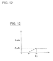
- FIG. 12 is a graph showing the relationship between the vehicle-widthwise distance ⁇ y to the dividing line and the size (enlargement amount ⁇ y 0 fs) of the detection region A1 in the second embodiment.
- the region setting unit 33b is designed to prevent the detection region A1 from enlarging too far by reducing the enlarged amount when enlarging the detection regions A1, A2. This prevents the detection region A1 from being set in subsequent traffic lanes and the precision of solid object detection from decreasing.
- the maximum limit y 0 fs' is preferably reduced to less than in the example shown in FIG. 8 . This is because it is thereby possible to further prevent the detection region A1 from being set in subsequent traffic lanes.
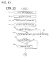
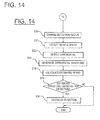
- FIGS. 13 and 14 are flowcharts showing the solid object detection method according to the second embodiment.
- the traffic lane width detection unit 35 detects the traffic lane width of the traveled lane based on image data captured by the camera 10 (S21).
- the region setting unit 33b sets an enlarged amount (S22). Specifically, the smaller the traffic lane width, the more the region setting unit 33b reduces the enlarged amount according to the vehicle-widthwise distance ⁇ y as shown in FIG. 12 . In this process, the region setting unit 33b preferably reduces the maximum limit y 0 fs' as well.
- steps S23 to S36 the same process as in steps S1 to S14 shown in FIG. 9 is executed.
- the precision of detecting solid objects can be improved, and situations such as those that would cause failures to detect solid objects can be (further) prevented, similar to the first embodiment. It is also possible to prevent situations such as those in which the detection regions A1, A2 are extremely contracted, causing detection failures.
- the smaller the traffic lane width of the traveled lane the smaller the enlarged amount when the sizes of the detection regions A1, A2 are enlarged. Therefore, in cases in which the traffic lane width it small, it is possible to prevent situations in which the detection regions A1, A2 are set not to an adjacent traffic lane but to a subsequent traffic lane.
- the solid object detection device and the solid object detection method according to the third embodiment are similar to those of the first embodiment, but the configuration and process specifics are partially different. The points of difference with the first embodiment are described below.
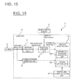
- FIG. 15 is a block diagram showing the details of the computer 30 according to the third embodiment.
- the camera 10 and the vehicle speed sensor 20 are also shown in order to give a clear depiction of the relationship of connection.
- the computer 30 comprises a traffic lane change detection unit (traffic lane variation detection means) 36, as shown in FIG. 15 .
- the traffic lane change detection unit 36 detects traffic lane changes by the vehicle V, calculates the extent of nearness to the dividing line based on the image data obtained by the image-capturing performed by the camera 10, for example, and assesses whether or not the vehicle V is changing traffic lanes.
- the traffic lane change detection unit 36 is not limited to the above process, and may assess traffic lane changes from the steered amount or by some other method.
- the traffic lane change detection unit 36 detects that the vehicle V is changing traffic lanes when the side surface of the vehicle V comes within a predetermined distance (e.g. 10 cm) of the dividing line.
- the traffic lane change detection unit 36 may also be designed to detect that the vehicle V is not changing traffic lanes when the side surface of the vehicle comes within a predetermined distance of the dividing line but then again separates from the dividing line by at least the predetermined distance.
- the traffic lane change detection unit 36 may assess that the traffic lane change is complete when the vehicle is separated from the dividing line by at least the predetermined distance after having changed traffic lanes (i.e., when the vehicle is separated from the dividing line by at least the predetermined distance after having crossed the dividing line by changing lanes.
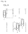
- FIG. 16 is a top view showing the traveled lane of the vehicle when the vehicle is changing traffic lanes.
- the vehicle V is positioned in the center of the traffic lane (see the symbol Va), and the vehicle then changes traffic lanes and reaches the position Vb.
- the vehicle-widthwise distance ⁇ y between the side surface of the vehicle V and the dividing line is temporarily longer. Therefore, the detection region A1 is enlarged and there is a possibility of another vehicle V in a subsequent traffic lane entering the detection region A1. In such cases, the precision of solid object detection is reduced.
- the region setting unit 33b when a traffic lane change made by the vehicle V is detected by the traffic lane change detection unit 36, for a certain time duration, the region setting unit 33b reduces the enlarged amount when the sizes of the detection regions A1, A2 are enlarged. Specifically, when a traffic lane change made by the vehicle V is detected by the traffic lane change detection unit 36, for a certain time duration, the region setting unit 33b reduces the enlarged amount ⁇ y 0 fs of the detection region A1 or A2 relative to the vehicle-widthwise distance ⁇ y between the side surface of the vehicle V shown in FIG. 16 and the dividing line.
- the region setting unit 33b reduces the enlarged amount ⁇ y 0 fs of the detection region A1 or A2 relative to the vehicle-widthwise distance ⁇ y between the side surface of the vehicle V and the dividing line to be less than before the traffic lane change, as shown in FIG. 17 . It is thereby possible to prevent situations in which the detection region A1 or A2 is temporarily enlarged by too much during a traffic lane change.
- FIG. 17 is a graph showing the relationship between the vehicle-widthwise distance and the size of the detection region (the enlarged amount ⁇ y 0 fs) in the third embodiment.
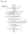
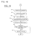
- FIGS. 18 and 19 are flowcharts showing the solid object detection method according to the third embodiment.
- the traffic lane change detection unit 36 calculates the extent of nearness to the dividing line and assesses whether or not the vehicle V is changing traffic lanes (S41). When it is assessed that the vehicle V is not changing traffic lanes (S41: NO), the process advances to step S43.
- the region setting unit 33b sets the enlarged amount (S42). Specifically, the region setting unit 33b reduces the enlarged amount according to the vehicle-widthwise distance ⁇ y, as shown in FIG. 17 . In this process, the region setting unit 33b preferably reduces the maximum limit y 0 fs' as well.
- steps S43 to S56 the same process as in steps S1 to S14 shown in FIG. 9 is executed.
- the precision of detecting solid objects can be improved, and situations such as those that would cause failures to detect solid objects can be (further) prevented, similar to the first embodiment. It is also possible to prevent situations such as those in which the detection regions A1, A2 are extremely contracted, causing detection failures.
- the enlarged amount for enlarging the sizes of the detection regions A1, A2 is reduced. Therefore, it is possible to prevent situations in which, while the vehicle is temporarily near the dividing line while changing traffic lanes, the detection regions A1, A2 are set not to an adjacent traffic lane but to a subsequent traffic lane.
- the solid object detection device and the solid object detection method according to the fourth embodiment are similar to those of the first embodiment, but the configuration and process specifics are partially different. The points of difference with the first embodiment are described below.
- FIG. 20 is a block diagram showing the details of the computer 30 according to the fourth embodiment.
- the camera 10 and the vehicle speed sensor 20 are also shown in order to give a clear depiction of the relationship of connection.
- the computer 30 comprises a ground line detection unit 37, as shown in FIG. 20 .
- the ground line detection unit 37 detects the positions where the tires of another vehicle V traveling on an adjacent traffic lane (positions in the vehicle-width direction) as ground lines. The details are described below using FIGS. 21 and 22 .
- FIGS. 21 and 22 are diagrams for describing the method of detecting ground lines by the ground line detection unit 37.
- the ground line detection unit 37 sets a plurality of lines L 1 to L n at different positions in the detection region A1 or A2, the lines being substantially parallel with the traveling direction of the vehicle V.
- the ground line detection unit 37 sets four substantially parallel lines.
- the following description uses four substantially parallel lines L 1 to L 4 as an example, but the lines are not limited to this example, and there may be two, three, five, or more parallel lines.
- the ground line detection unit 37 then causes the differential waveform generation unit 33a to generate differential waveforms DW t for the set lines L 1 to L 4 . Specifically, after causing the differential waveform generation unit 33a to count the number of differential pixels DP, the ground line detection unit 37 finds the intersecting points CP between the lines L 1 to L 4 and the line La along the direction in which the solid object falls in the data of the differential images DW t , and causes the differential waveform generation unit 33a to generate a differential waveform DW t for each of the lines L 1 to L 4 by correlating the intersection points CP and the counted number. The ground line detection unit 37 can thereby obtain a plurality of differential waveforms as shown in FIG. 21(b) . In FIG.
- the differential wavefrom DW t1 is based on the substantially parallel line L 1
- the differential waveform DW t2 is based on the substantially parallel line L 2
- the differential waveform DW t3 is based on the substantially parallel line L 3
- the differential waveform DW t4 is based on the substantially parallel line L 4 .
- the differential waveform DW t3 based on the substantially parallel line L 3 near the vehicle V has more of a tendency for frequency to increase than the differential waveforms DW t1 , DW t2 based on the substantially parallel lines L 1 , L 2 farther from the vehicle V.
- the other vehicle V is a solid object, and the other vehicle V therefore assuredly extends to an infinite distance within the differential image PD.
- the differential waveform DW t3 and the differential waveform DW t4 have the same frequency. This is because the substantially parallel lines L 3 , L 4 both overlap the other vehicle V in the differential image PD t . Specifically, this is because there are no differential pixels DP between the substantially parallel line L 3 and line L 4 .
- the ground line detection unit 37 assesses the ground line L t of the other vehicle V from the changes in the shapes of the plurality of differential waveform DW t1 to DW t4 described above. In the case of the example shown in FIG. 21(b) , the ground line detection unit 37 assesses the substantially parallel line L 3 to be the ground line L t . Specifically, the ground line L t is assessed from the rates of increase in region shown in FIG. 22.
- FIG. 22 is a graph showing the rates of increase in the areas of the plurality of differential waveforms DW t1 to DW t4 shown in FIG. 21(b) .
- the ground line detection unit 37 references the rates of increase in region from furthest the substantially parallel line among the calculated areas toward the nearest substantially parallel line, as shown in FIG. 22 .
- the region of the differential waveform DW t2 exhibits a rate of increase that is constant relative to the region of the differential waveform DW t1
- the region of the differential waveform DW t3 exhibits a rate of increase that is constant relative to the region of the differential waveform DW t2 .
- the region of the differential waveform DW t4 and the region of the differential waveform DW t3 are equal, and the rate of increase is a predetermined value or less. This is because there are no differential pixels DP between the substantially parallel line L 3 and line L 4 as described above.
- the ground line detection unit 37 detects the substantially parallel line L 3 as the ground line L t of the other vehicle V.
- the region setting unit 33b enlarges the sizes of the detection regions A1, A2 based on the vehicle-widthwise distance ⁇ y between the side surface of the vehicle V and the dividing line, similar to the first embodiment. Furthermore, in the fourth embodiment, the region setting unit 33b changes the enlarged amount ⁇ y 0 fs when enlarging the detection regions A1, A2 outward in the vehicle-width direction, based on the ground line L t of the other vehicle V detected by the ground line detection unit 37.
- the region setting unit 33b reduces the enlarged amount ⁇ y 0 fs when enlarging the sizes of the detection regions A1, A2, as shown in FIG. 23 .
- the precision of detecting solid objects can be improved, and situations such as those that would cause failures to detect solid objects can be (further) prevented, similar to the first embodiment. It is also possible to prevent situations such as those in which the detection regions A1, A2 are extremely contracted, causing detection failures.
- the ground line L t of the other vehicle V traveling in an adjacent traffic lane is detected, and the shorter the distance from the side surface of the vehicle V to the ground line L t , the more the changed amount ⁇ y 0 fs is reduced when the sizes of the detection regions A1, A2 are enlarged.
- the solid object detection device and the solid object detection method according to the fifth embodiment are similar to those of the first embodiment, but the configuration and process specifics are partially different. The points of difference with the first embodiment are described below.
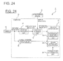
- FIG. 24 is a block diagram showing the details of the computer 30 according to the fifth embodiment.
- the camera 10 and the vehicle speed sensor 20 are also shown in order to give a clear depiction of the relationship of connection.
- the computer 30 comprises a turning state determination unit (turning state determination means) 38, as shown in FIG. 24 .
- the turning state determination unit 38 determines whether or not the vehicle V is in a state of turning based on the vehicle speed detected by the vehicle speed sensor 20 or the steering amount detected by a steering angle sensor (not shown), and also detects the turning radius of the vehicle V when the vehicle V is in a state of turning.
- the method by which the turning state is detected by the turning state determination unit 38 is not particularly limited; the turning state of the vehicle V 1 may be detected based on the detection results of a lateral acceleration sensor, for example, or the turning state of the vehicle V1 may be detected by predicting the road shape based on the image captured by the camera 10.
- the turning state of the vehicle V1 may also be detected by specifying the road on which the vehicle V is traveling in accordance with map information or current position information of the vehicle V according to a navigation system or the like.
- the region setting unit 33b enlarges the detection regions A1, A2 based on the vehicle-widthwise distance ⁇ y between the side surface of the vehicle V and the dividing line, similar to the first embodiment, and in the fifth embodiment, the region setting unit 33b also changes the enlarged amount ⁇ y 0 fs when the sizes of the detection regions A1, A2 are enlarged in accordance with the turning radius of the vehicle V, when the vehicle V is determined by the turning state determination unit 38 to be in a state of turning. Specifically, the smaller the turning radius of the vehicle V, the smaller the region setting unit 33b makes the enlarged amount ⁇ y 0 fs of the detection regions A1, A2.
- FIG. 25 is a top view showing the traveling state of the vehicle when the vehicle is turning, and also showing an example of a case in which the region setting unit 33b has enlarged the detection region A1.
- the region setting unit 33b has enlarged the detection region A1.
- the smaller the turning radius of the vehicle V the easily the detection regions A1, A2 on the outer sides of the turning direction are set inside the subsequent traffic lanes, and when the detection region A1 is enlarged outward in the vehicle-width direction in the same manner as the first embodiment, there are cases in which another vehicle V in a subsequent traffic lane enters the detection region A1 and this other vehicle V is mistakenly detected as an adjacent vehicle.
- the region setting unit 33b makes the enlarged amount ⁇ y 0 fs of the detection regions A1, A2 relative to the vehicle-widthwise distance ⁇ y, as shown in FIG. 26 . It is thereby possible to keep the detection regions A1, A2 from being set in subsequent traffic lanes even when the vehicle V is turning through a curve, and as a result, other vehicles V in subsequent traffic lanes can be effectively prevented from being mistakenly detected as adjacent vehicles.
- the region setting unit 33b in the fifth embodiment can also employ a configuration for reducing the enlarged amount ⁇ y 0 fs of the detection regions A1, A2 based on the traffic lane width of the traffic lane traveled by the vehicle V, as disclosed in the second embodiment.
- the region setting unit 33b can compare the enlarged amount ⁇ y 0 fs of the detection regions A1, A2 determined based on the turning radius and the enlarged amount ⁇ y 0 fs of the detection regions A1, A2 determined based on the traffic lane width, select the smaller enlarged amount ⁇ y 0 fs, and enlarge the sizes of the detection regions A1, A2 outward in the vehicle-width direction.
- the precision of detecting solid objects can be improved, and situations such as those that would cause failures to detect solid objects can be (further) prevented, similar to the first embodiment. It is also possible to prevent situations such as those in which the detection regions A1, A2 are extremely contracted, causing detection failures.
- the detection regions A1, A2 when the vehicle V is determined by the turning state determination unit 38 to be turning, the smaller the turning radius of the vehicle V, the smaller the enlarged amount ⁇ y 0 fs of the detection regions A1, A2 relative to the vehicle-widthwise distance ⁇ y as shown in FIG. 26 , whereby the detection regions A1, A2 can be kept from being set in subsequent traffic lanes even when the vehicle V is turning through a curve as shown in FIG. 25 , and as a result, other vehicles V in subsequent traffic lanes can be effectively prevented from being mistakenly detected as adjacent vehicles.
- the enlarged amount ⁇ y 0 fs of the detection regions A1, A2 can be suppressed based on the turning state of the vehicle V. For example, when the vehicle V1 is traveling on a straight road and when the vehicle V is detected to be turning, it can be assessed that the smaller the turning radius, the higher the possibility that the vehicle V is making a traffic lane change.
- the solid object detection device and the solid object detection method according to the sixth embodiment are similar to those of the first embodiment, but the configuration and process specifics are partially different. The points of difference with the first embodiment are described below.
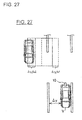
- FIG. 27 is a top view showing the traveling state of the vehicle in the sixth embodiment, and also showing an example of a case in which the region setting unit 33b has enlarged the detection region A1.
- the region setting unit 33b shifts the detection regions A1, A2 outward in the vehicle-width direction based on the vehicle-widthwise distance ⁇ y between the side surface of the vehicle V and the dividing line, and enlarges the detection regions A1, A2 outward in the vehicle-width direction based on the vehicle-widthwise distance ⁇ y between the side surface of the vehicle V and the dividing line.
- the details are described below.
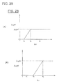
- FIG. 28(A) is a graph showing the relationship between the vehicle-widthwise distance ⁇ y to the dividing line and the movement amount (the shift amount y 0 fs1) when the detection regions A1, A2 are shifted outward in the vehicle-width direction
- FIG. 28(B) is a graph showing the relationship between the vehicle-widthwise distance ⁇ y to the dividing line and the enlarged amount (the enlarged amount ⁇ y 0 fs2) when the detection regions A1, A2 are enlarged outward in the vehicle-width direction.
- the region setting unit 33b leaves the detection regions A1, A2 unchanged, and when the vehicle-widthwise distance ⁇ y is y 3 or greater and less than y 4 , the region setting unit 33b shifts the detection regions A1, A2 outward in the vehicle-width direction according to the vehicle-widthwise distance ⁇ y.
- the detection regions A1, A2 are not enlarged outward in the vehicle-width direction.
- the region setting unit 33b shifts the detection regions A1, A2 outward in the vehicle-width direction by a predetermined shift amount y 0 fs1' and enlarges the detection regions A1, A2 outward in the vehicle-width direction, as shown in FIG. 28(A) .
- the detection regions A1, A2 are enlarged outward in the vehicle-width direction according to the vehicle-widthwise distance ⁇ y as shown in FIG. 28(B)
- the detection regions A1, A2 are enlarged outward in the vehicle-width direction by a predetermined enlarged amount ⁇ y 0 fs2'.
- the region setting unit 33b thereby shifts the detection regions A1, A2 outward in the vehicle-width direction in accordance with the vehicle-widthwise distance ⁇ y when the vehicle-widthwise distance ⁇ y between the side surface of the vehicle V and the dividing line is y 3 or greater, and when the vehicle-widthwise distance ⁇ y thereafter is y 4 or greater, the region setting unit 33b stops shifting the detection regions A1, A2 outward in the vehicle-width direction and instead enlarges the detection regions A1, A2 outward in the vehicle-width direction.
- the region setting unit 33b then enlarges the detection regions A1, A2 outward in the vehicle-width direction in accordance with the vehicle-widthwise distance ⁇ y until the vehicle-widthwise distance ⁇ y reaches y 5 , and at the point in time when the vehicle-widthwise distance ⁇ y reaches y 5 , the region setting unit 33b also stops enlarging the detection regions A1, A2 outward in the vehicle-width direction.
- the region setting unit 33b narrows the sizes of the enlarged detection regions A1, A2 inward in the vehicle-width direction.
- the region setting unit 33b stops contracting the detection regions A1, A2 inward in the vehicle-width direction and instead shifts the detection regions A1, A2 inward in the vehicle-width direction in accordance with the vehicle-widthwise distance ⁇ y.
- the region setting unit 33b then also stops shifting the detection regions A1, A2 inward in the vehicle-width direction.
- the region setting unit 33b has limit values (enlargement prescribed values, prescribed values) for the amounts of change according to various conditions when the vehicle V is changing traffic lanes, when a solid object is sensed, and during normal times (when the vehicle V is traveling straight and when a solid object is not detected), for both the shift amount y 0 fs1 and the enlarged amount ⁇ y 0 fs2 of the detection regions A1, A2.
- the region setting unit 33b then gradually shifts the detection regions A1, A2 outward in the vehicle-width direction within a range that does not exceed the limit values of ⁇ y 0 fs1 and ⁇ y 0 fs2 according to the various conditions, and gradually enlarges the sizes of the detection regions A1, A2 outward in the vehicle-width direction.
- the limit values for each condition described above are applied regardless of the turning state of the vehicle or the traffic lane width of the traveled lane.
- the precision of detecting solid objects can be improved, and situations such as those that would cause failures to detect solid objects can be (further) prevented, similar to the first embodiment. It is also possible to prevent situations such as those in which the detection regions A1, A2 are extremely contracted, causing detection failures.
- the detection regions A1, A2 are shifted outward in the vehicle-width direction based on the vehicle-widthwise distance ⁇ y between the side surface of the vehicle V and the dividing line, and when the vehicle-widthwise distance ⁇ y thereafter reaches a predetermined value or greater and the shifted amount of the detection regions A1, A2 reaches a predetermined amount, the following effects can be achieved by enlarging the detection regions A1, A2 outward in the vehicle-width direction instead of shifting the detection regions A1, A2.
- the solid object detection device and the solid object detection method according to the seventh embodiment are similar to those of the first embodiment, but the configuration and process specifics are partially different. The points of difference with the first embodiment are described below.
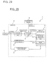
- FIG. 29 is a block diagram showing the details of the computer 30 according to the seventh embodiment.
- the camera 10 and the vehicle speed sensor 20 are also shown in order to give a clear depiction of the relationship of connection.
- the computer 30 comprises a foreign substance detection unit (foreign substance detection means) 39, as shown in FIG. 29 .
- the foreign substance detection unit 39 detects foreign substances such as rainwater or water stains adhering to the lens.
- the foreign substance detection unit 39 detects the amount of rainwater adhering to the lens by detecting the operating strength of a wiper or of a rainwater sensor which detects the amount of rainwater adhering to the lens by radiating infrared light onto the lens and detecting the amount by which the radiated infrared light is attenuated by the rainwater; and the foreign substance detection unit 39 outputs the detected amount of rainwater to the region setting unit 33b.
- the foreign substance detection unit 39 is not limited to detecting rainwater, and may, for example, also detect water stains or mud adhering to the lens. For example, by extracting the edge of a photographed subject from the captured image and assessing the sharpness of the image from the characteristics of the extracted edge, the foreign substance detection unit 39 may assess the extent to which water stains or the like are adhering to the lens and the lens is clouded (a white thin film is formed on the lens surface), and may thereby detect the amount of foreign substances adhering to the lens. Otherwise, when an edge of similar intensity is detected in the same region in the captured image over a certain time duration, the foreign substance detection unit 39 may assess that foreign substances are adhering to this region and detect the amount of foreign substances adhering to the lens.
- the region setting unit 33b enlarges the detection regions A1, A2 outward in the vehicle-width direction based on the vehicle-widthwise distance ⁇ y between the side surface of the vehicle V and the dividing line similar to the first embodiment, and in the seventh embodiment also varies the enlarged amount ⁇ y 0 fs when enlarging the detection regions A1, A2 based on the amount of foreign substances detected by the foreign substance detection unit 39. Specifically, the greater the amount of foreign substances adhering to the lens, the smaller the region setting unit 33b makes the enlarged amount ⁇ y 0 fs when enlarging the detection regions A1, A2.
- FIG. 30 is a graph showing the relationship between the amount of foreign substances adhering to the lens and the sizes of the detection regions A1, A2 (the enlarged amount ⁇ y 0 fs).
- the region setting unit 33b keeps the enlarged amount ⁇ y 0 fs of the detection regions A1, A2 at the initial enlarged amount determined based on the vehicle-widthwise distance ⁇ y.
- the region setting unit 33b sets the enlarged amount of the detection regions A1, A2 to the smallest predetermined value ⁇ y 0 fs".
- the precision of detecting solid objects can be improved, and situations such as those that would cause failures to detect solid objects can be (further) prevented, similar to the first embodiment. It is also possible to prevent situations such as those in which the detection regions A1, A2 are extremely contracted, causing detection failures.
- the amount of foreign substances adhering to the lens of the camera 10 are detected, and the greater the amount of foreign substances, the smaller the enlarged amount ⁇ y 0 fs of the detection regions A1, A2.
- the greater the amount of foreign substances adhering to the lens the more of the luminous flux from the photographed subject is blocked and irregularly reflected by the foreign substances, and as a result, there are cases in which the image of the dividing line captured by the camera 10 is distorted or fogged, and the precision of detecting the dividing line is reduced.
- the enlarged amount ⁇ y 0 fs of the detection regions A1, A2 is reduced, whereby it is possible to effectively prevent the enlarged amount of the detection regions A1, A2 from being too large due to an error in detecting the vehicle-widthwise distance ⁇ y between the side surface of the vehicle V and the dividing line, and to effectively prevent other vehicles traveling in subsequent traffic lanes, grass outside of the road, and the like from being mistakenly detected as adjacent vehicles.
- the solid object detection device and the solid object detection method according to the eighth embodiment are similar to those of the first embodiment, but the configuration and process specifics are partially different. The points of difference with the first embodiment are described below.
- FIG. 31 is a block diagram showing the details of the computer 30 according to the eighth embodiment.
- the camera 10 and the vehicle speed sensor 20 are also shown in order to give a clear depiction of the relationship of connection.
- the computer 30 comprises a dividing line type specifying unit (dividing line type specifying means) 40, as shown in FIG. 31 .
- the dividing line type specifying unit 40 specifies the type of dividing line based on the image captured by the camera 10.
- the method for specifying the type of dividing line is not particularly limited, but the dividing line type specifying unit 40 can, for example, specify the type of dividing line by performing pattern matching on the dividing line imaged by the camera 10. Otherwise, the dividing line type specifying unit 40 can specify the type of dividing line from map information by specifying the road (traffic lane) on which the vehicle V is traveling, in accordance with map information or the current position information of the vehicle V in a navigation system or the like.
- the region setting unit 33b enlarges the detection regions A1, A2 outward in the vehicle-width direction based on the vehicle-widthwise distance ⁇ y between the side surface of the vehicle V and the dividing line similar to the first embodiment, and in the eighth embodiment, the region setting unit 33b also varies the enlarged amount ⁇ y 0 fs when enlarging the detection regions A1, A2 based on the type of dividing line specified by the dividing line type specifying unit 40.
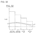
- FIG. 32 is a diagram showing the relationship between the type of dividing line and the size of the detection regions A1, A2.
- the region setting unit 33b is capable of specifying four types of dividing lines: a white dashed line, a white solid line, a yellow line, and a multiple line.
- the region setting unit 33b assesses from these four types of dividing lines that the possibility is highest that the region adjacent to the lane traveled by the vehicle V is an adjacent traffic lane, and increases the enlarged amount ⁇ y 0 fs of the detection regions A1, A2 by the greatest amount among these four types of dividing lines.
- the region setting unit 33b assesses that there is a possibility that the region next to the lane traveled by the vehicle V is an adjacent traffic lane, and sets the enlarged amount ⁇ y 0 fs of the detection regions A1, A2 so that the enlarged amount ⁇ y 0 fs is smaller than that of the white dashed line but larger than that of other dividing lines.
- the region setting unit 33b assesses that the possibility is low that the region next to the lane traveled by the vehicle V is an adjacent traffic lane, and reduces the enlarged amount ⁇ y 0 fs of the detection regions A1, A2.
- the region setting unit 33b assesses that the possibility is lowest that the region next to the lane traveled by the vehicle V is an adjacent traffic lane, and reduces the enlarged amount ⁇ y 0 fs of the detection regions A1, A2 by the greatest amount among these four types of dividing lines.
- the precision of detecting solid objects can be improved, and situations such as those that would cause failures to detect solid objects can be (further) prevented, similar to the first embodiment. It is also possible to prevent situations such as those in which the detection regions A1, A2 are extremely contracted, causing detection failures.
- the type of dividing line is specified, and a different enlarged amount ⁇ y 0 fs of the detection regions A1, A2 is used based on the specified type of dividing line.
- the type of dividing line is a yellow line or a multiple line, it is possible that the region next to the lane traveled by the vehicle V is the shoulder, outside of the road, or an oncoming traffic lane, in which case there is a greater possibility that grass, noise, or the like outside of the road will be detected when the detection regions A1, A2 are enlarged, and the precision of detecting solid objects (other vehicles and the like) decreases.
- the type of dividing line when the type of dividing line is a yellow line or a multiple line, for example, detection of grass, noise, or the like outside of the road can be effectively suppressed by suppressing the enlarging of the detection regions A1, A2.
- the type of dividing line is a dashed white line or a solid white line
- the region next to the lane traveled by the vehicle V is possibly an adjacent traffic lane, in which case a solid object (another vehicle V) in the adjacent traffic lane can be appropriately detected by appropriately enlarging the detection regions A1, A2 in accordance with the vehicle-widthwise distance ⁇ y.
- a configuration was exemplified in which the enlarged amount ⁇ y 0 fs when enlarging the sizes of the detection regions A1, A2 was reduced for a certain time duration in cases in which a traffic lane change made by the vehicle V was detected by the traffic lane change detection unit 36, but a possible addition to this configuration is one in which the movement speed of the vehicle V in the vehicle-width direction is calculated when a traffic lane change made by the vehicle V is detected, and the higher the movement speed of the vehicle V in the vehicle-width direction, the smaller the enlarged amount ⁇ y 0 fs when enlarging the sizes of the detection regions A1, A2.
- the higher the movement speed of the vehicle V in the vehicle-width direction the higher of a possibility of the vehicle V changing traffic lanes that can be assessed. Therefore, by making the enlarged amount ⁇ y 0 fs of the detection regions A1, A2 smaller the higher the movement speed of the vehicle V in the vehicle-width direction, it is possible to effectively prevent the detection regions A1, A2 from being enlarged by too much and the detection regions A1, A2 from being set in subsequent traffic lanes due to the vehicle V changing traffic lanes.
- the method for calculating the movement speed of the vehicle V in the vehicle-width direction is not particularly limited, and the region setting unit 33b can calculate the movement speed of the vehicle V in the vehicle-width direction, either based on the change over time in the vehicle-widthwise distance ⁇ y from the side surface of the vehicle V to the dividing line as detected by the lateral position detection unit 34, or by using a lateral acceleration sensor (not shown).
- a configuration was exemplified in which after the detection regions A1, A2 are shifted outward in the vehicle-width direction based on the vehicle-widthwise distance ⁇ y from the side surface of the vehicle V to the dividing line, the sizes of the detection regions A1, A2 are enlarged outward in the vehicle-width direction, but the configuration is not limited as such, and another possible option is that the sizes of the detection regions A1, A2 be enlarged outward in the vehicle-width direction while the detection regions A1, A2 are simultaneously shifted outward in the vehicle-width direction, for example.
- the speed of the vehicle V is assessed based on a signal from the vehicle speed sensor 20, but assessing the vehicle speed is not limited as such, and the vehicle speed may be estimated from a plurality of images of different times. In this case, the vehicle speed sensor is unnecessary, and the configuration can be simplified. The vehicle behavior may also be assessed solely from images.
- a captured image of the current time and an image of one time prior are converted to bird's-eye view views
- a differential image PD t is generated upon combining the converted bird's-eye view views
- the generated differential image PD t is evaluated along the falling direction (the direction in which the solid object falls when the captured images are converted to bird's-eye view views) to generate a differential waveform DW t
- the present invention is not limited as such.
- the converted bird's-eye view view is converted to an equivalent of the captured image after being positionally aligned, a differential image is generated from this image and an image of the current time, and a differential waveform DW t is generated by evaluating the generated differential image along a direction equivalent to the falling direction (i.e., a direction obtained by converting the falling direction to a direction on the captured image).
- a differential image PD t is generated from the differential of the two positionally aligned images, and the differential image PD t can be evaluated along the falling direction of the solid object when the image is converted to an bird's-eye view view; it is not absolutely necessary to generate an bird's-eye view view.
- the solid object detection devices 1 to 3 detect a solid object based on the differential waveform DW t , but are not limited as such, and may, for example, detect a solid object by using an optical flow or an image template. Furthermore, detecting the solid object is limited to using the differential waveform DW t , and the differential image PD t may be used. Furthermore, when the sizes of the detection regions A1, A2 are enlarged, the sizes of the detection regions A1, A2 themselves are changed in the present embodiment, but the present invention is not limited as such and enlargement areas separate from the detection regions A1, A2 maybe set.
- the positional alignment unit 32 in the present embodiment positionally aligns the positions of bird's-eye view view images of different times in an bird's-eye view view, but this "positionally aligning" process can be performed with a precision corresponding to the type of detection objective or the required detection precision.
- strict positional alignment may be performed based on the same time or the same position, or lax positional aligmnent may be performed only enough to perceive coordinates of the bird's-eye view images.
Landscapes
- Physics & Mathematics (AREA)
- General Physics & Mathematics (AREA)
- Engineering & Computer Science (AREA)
- Multimedia (AREA)
- Theoretical Computer Science (AREA)
- Traffic Control Systems (AREA)
- Image Analysis (AREA)
- Image Processing (AREA)
Abstract
Description
- The present invention relates to a solid object detection device and a solid object detection method.
- In the past, there have been proposed vehicle periphery observation devices which use radar to assess whether or not there is a solid object in a detection region behind the vehicle, and notify the driver. With such a vehicle periphery observation device, the detection region includes a location that is a blind spot of at least a side mirror, and when the angle of the side mirror changes, the position of the detection region is changed accordingly (see Patent Document 1).
- [Patent Document 1] Japanese Laid-Open Patent Publication No.
2000-149197 - However, in the device disclosed in
Patent Document 1, there is a possibility, depending on the position of the vehicle in the traffic lane, that a solid object such as another vehicle in an adjacent traffic lane cannot be detected. To give a more detailed description, in the device disclosed inPatent Document 1, the detection region is fixed as long as the angle of the side mirror does not change. In such a state, in cases such as when the vehicle nears the left side of the traffic lane and the other vehicle or the like in the right adjacent traffic lane is near the right side of the first traffic lane, for example, the other vehicle does not enter the detection region and the solid object can no longer be detected. - The present invention was devised in order to solve such problems in the prior art, it being an object of the invention to provide a solid object detection device and a solid object detection method whereby the precision of detecting solid objects can be improved.
- The solid object detection device of the present invention captures an image including a dividing line and a predetermined region of an adjacent traffic lane, and assesses whether or not there is a solid object in the predetermined region. From the captured image, the solid object detection device detects a vehicle-widthwise distance between the vehicle position and the dividing line in the traffic lane traveled by the vehicle, and the size of the predetermined region positioned on the side where the dividing line is located increases farther outward in the vehicle-width direction in correspondence with a greater the vehicle-widthwise distance.
- According to the present invention, the predetermined region in which the vehicle-widthwise distance is positioned on the side where the dividing line is located is enlarged farther outward in the vehicle-width direction correspondingly with respect to an increase in the vehicle-widthwise distance between the vehicle position and the dividing line. Therefore, it is possible to avoid situations in which due to the vehicle being separated from the dividing line, for example, the predetermined region is not set appropriate to the adjacent vehicle, and a solid object such as another vehicle is outside of the predetermined region and fails to be detected. Therefore, the precision of detecting solid objects can be improved.
-
-
FIG. 1 is a schematic diagram of the solid object detection device according to the present embodiment, showing an example of a case in which the solid object detection device is installed in a vehicle; -
FIG. 2 is a top view showing the traveling state of the vehicle shown inFIG. 1 ; -
FIG. 3 is a block diagram showing the details of the computer shown inFIG. 1 ; -
FIG. 4 is a drawing for describing an outline of the process of the positional alignment unit shown inFIG. 3 , wherein (a) shows the movement state of the vehicle V and (b) shows an outline of positional alignment; -
FIG. 5 is a schematic diagram showing the manner in which differential waveforms are generated by the differential waveform generation unit shown inFIG. 3 ; -
FIG. 6 is a top view showing the traveling state of the vehicle shown inFIG. 1 , and showing an example of a case in which the vehicle is traveling off-center in the travel lane; -
FIG. 7 is a top view showing the traveling state of the vehicle shown inFIG. 1 , and showing an example of a case in which the region setting unit has enlarged the detection region; -
FIG. 8 is a graph showing the relationship between the vehicle-widthwise distance to the dividing line and the size (enlarged amount) of the detection region; -
FIG. 9 is a flowchart showing the solid object detection method according to the present embodiment; -
FIG. 10 is a block diagram showing the details of the computer according to the second embodiment; -
FIG. 11 is a top view showing the traveling state of the vehicle when the traffic lane width is small, and showing an example of a case in which the region setting unit has enlarged the detection region; -
FIG. 12 is a graph showing the relationship between the vehicle-widthwise distance to the dividing line and the size (enlargement amount) of the detection region in the second embodiment; -
FIG. 13 is a flowchart showing the solid object detection method according to the second embodiment, showing the first half of the process; -
FIG. 14 is a flowchart showing the solid object detection method according to the second embodiment, showing the second half of the process; -
FIG. 15 is a block diagram showing the details of the computer according to the third embodiment; -
FIG. 16 is a top view showing the traveling state of the vehicle during a traffic lane change; -
FIG. 17 is a graph showing the relationship between the vehicle-widthwise distance to the dividing line and the size (enlargement amount) of the detection region in the third embodiment; -
FIG. 18 is a flowchart showing the solid object detection method according to the third embodiment, showing the first half of the process; -
FIG. 19 is a flowchart showing the solid object detection method according to the third embodiment, showing the second half of the process; -
FIG. 20 is a block diagram showing the details of thecomputer 30 according to the fourth embodiment; -
FIG. 21 is a schematic diagram showing the specifics of the process performed by the groundline detection unit 37; -
FIG. 22 is a graph showing the rates of increase in the areas of the plurality of differential waveforms DWt1 to DWt4 shown inFIG. 21(b) ; -
FIG. 23 is a graph showing the relationship between the vehicle-widthwise distance to the dividing line and the size (enlargement amount) of the detection region in the fourth embodiment; -
FIG. 24 is a block diagram showing the details of thecomputer 30 according to the fifth embodiment; -
FIG. 25 is a graph showing the relationship between the vehicle-widthwise distance to the dividing line and the size (enlargement amount) of the detection region in the fifth embodiment; -
FIG. 26 is a top view showing the traveling state of the vehicle when the vehicle is turning; -
FIG. 27 is a top view showing the traveling state of the vehicle in the sixth embodiment; -
FIG. 28 is a graph showing the relationship between the vehicle-widthwise distance to the dividing line and the size (enlargement amount) of the detection region in the sixth embodiment; -
FIG. 29 is a block diagram showing the details of thecomputer 30 according to the seventh embodiment; -
FIG. 30 is a graph showing the relationship between the vehicle-widthwise distance to the dividing line and the size (enlargement amount) of the detection region in the seventh embodiment; -
FIG. 31 is a block diagram showing the details of thecomputer 30 according to the eighth embodiment; and -
FIG. 32 is a diagram for describing the relationship between the type of dividing line and the size (enlarged amount) of the detection regions A1, A2. - Preferred embodiments of the present invention are described below based on the drawings.
FIG. 1 is a schematic diagram of the solidobject detection device 1 according to the present embodiment, showing an example of a case in which the solidobject detection device 1 is installed in a vehicle V. The solidobject detection device 1 shown inFIG. 1 detects solid objects (e.g. other vehicles, two-wheeled vehicles, etc.) traveling in an adjacent traffic lane that is adjacent to the traveled lane on which the vehicle V is traveling, the adjacent traffic lane being adjacent across a dividing line as a border; the solidobject detection device 1 provides various information to the driver of the vehicle V; and the solidobject detection device 1 comprises a camera (image-capturing means) 10, avehicle speed sensor 20, and acomputer 30. The term "traveled lane" used below refers to a travel band on which the vehicle V can travel when there are no lane changes, which is also a region that excludes the dividing line. At the same time, the term "adjacent traffic lane" refers to a travel band adjacent to the traveled lane across the dividing line, which is also a region that excludes the dividing line. The dividing line is a line such as the white lines or the like that serve as the border between the traveled lane and the adjacent traffic lane. - The
camera 10 shown inFIG. 1 is attached so at a location at a height h in the rear of the vehicle V, an optical axis is at an angle θ downward from horizontal. Thecamera 10 is designed to take images of the detection region from this position. Thevehicle speed sensor 20 detects the traveling speed of the vehicle V, for which a sensor or the like for sensing the rotating speed of the wheels, for example, is applied. Based on the images captured by thecamera 10, thecomputer 30 detects solid objects (e.g. other vehicles, two-wheeled vehicles, etc.) located to the rear of the vehicle V. - The solid
object detection device 1 also has a warning device (not shown), and issues warnings to the driver of the vehicle V in cases such as when there is a possibility of a shifting operation detected by thecomputer 30 coming in contact with the vehicle V. -
FIG. 2 is an bird's-eye view view showing the traveling state of the vehicle V shown inFIG. 1 . Thecamera 10 is capable of image-capturing a region to the rear of the vehicle V, or specifically a region including the dividing line and the adjacent traffic lane, as shown inFIG. 2 . Detection regions (predetermined areas) A1, A2 for detecting solid objects such as other vehicles are set in adjacent traffic lanes that are adjacent to the traveled lane in which the vehicle V is traveling, and thecomputer 30 detects whether or not there are solid objects in the detection regions A1, A2. Such detection regions A1, A2 are set from their relative positions with respect to the vehicle V. -
FIG. 3 is a block diagram showing the details of thecomputer 30 shown inFIG. 1 . InFIG. 3 , thecamera 10 and thevehicle speed sensor 20 are also shown in order to give a clear depiction of the relationship of connection. - The
computer 30 comprises aviewpoint conversion unit 31, a positional alignment unit (positional alignment means) 32, and a solid object detection unit (solid object detection means) 33, as shown inFIG. 3 . - The
viewpoint conversion unit 31 inputs captured image data including the detection regions A1, A2 obtained by the image-capturing performed by thecamera 10, and converts the viewpoint of the inputted captured image data into bird's-eye view image data which is seen as viewed from bird's-eye view. This bird's-eye view view is what would be seen from the viewpoint of an imaginary camera looking vertically downward, for example, from the air above. This viewpoint conversion is performed as is disclosed in Japanese Laid-Open Patent Publication No.2008-219063 - The
positional alignment unit 32 sequentially inputs the bird's-eye view image data obtained by the viewpoint conversion of theviewpoint conversion unit 31, and matches the position of inputted bird's-eye view image data of a different time.FIG. 4 is a top view showing an outline of the process of thepositional alignment unit 32 shown inFIG. 3 , wherein (a) shows the movement state of the vehicle V and (b) shows an outline of positional alignment. - As shown in
FIG. 4(a) , the vehicle V of the current time is positioned at V1, and the vehicle V at one time prior is positioned at V2. Another vehicle V is traveling parallel to the vehicle V in a position to the rear of the vehicle V, the other vehicle V of the current time is positioned at V3, and the other vehicle V of one time prior is positioned at V4. Furthermore, the vehicle V moves a distance d in one time. The term "one time prior" may refer to a time in the past from the current time by a time duration established in advance (e.g. one control cycle), or it may refer to a time in the past by any desired time duration. - In such a state, the bird's-eye view image PBt at the current time is shown in
FIG. 4(b) . In the bird's-eye view image PBt, the white lines painted on the road are rectangular and are in a state of being seen from above comparatively accurately. However, the other vehicle V3 is beginning to fall into the image. Similarly, in the bird's-eye view image PBt-1 at one time prior, the white lines painted on the road are rectangular and are in a state of being seen from above comparatively accurately, but the other vehicle V4 is beginning to fall into the image. - The
positional alignment unit 32 implements the positional alignment of the bird's-eye view images PBt, PBt-1 described above in terms of data. At this time, thepositional alignment unit 32 offsets the bird's-eye view image PBt-1 at the one time prior, and causes the position to coincide with the bird's-eye view image PBt at the current time. The offset amount d' is merely an amount corresponding to the travel distance d shown inFIG. 4(a) , and is determined based on a signal from thevehicle speed sensor 20 and on the time duration from the one time prior to the current time. - After the positional alignment, the
positional alignment unit 32 finds the differential between the bird's-eye view images PBt, PBt-1, and generates data of a differential image PDt. The pixel value of the differential image PDt may be the absolute value of the difference in pixel values between the bird's-eye view images PBt, PBt-1, or, in order to correspond with changes in the illuminated environment, it may be "1" when the absolute value exceeds a predetermined value and "0" when the absolute value does not exceed a predetermined value. -
FIG. 3 is again referenced. Furthermore, thecomputer 30 comprises a lateral position detection unit (lateral position detection means) 34. Based on the captured image data captured by thecamera 10, the lateralposition detection unit 34 detects the vehicle position (specifically the side surface of the vehicle V) in the traffic lane traveled by the vehicle V, and the vehicle-widthwise distance to the dividing line that divides the traffic lane. The lateralposition detection unit 34 makes it possible for thecomputer 30 to detect things such as whether the vehicle is traveling through the center of the traveled lane or traveling nearer toward either the left or right side. - Furthermore, the solid
object detection unit 33 detects solid objects based on the data of the differential image PDt such as is shown inFIG. 4 . The solidobject detection unit 33 comprises a differential waveform generation unit (differential waveform generation means) 33a and a region setting unit (region setting means) 33b. -
FIG. 5 is a schematic diagram showing the manner in which differential waveforms are generated by the differentialwaveform generation unit 33a shown inFIG. 3 . The differentialwaveform generation unit 33a generates a differential waveform DWt from the portions in the differential image PDt that are equivalent to the detection regions A1, A2, as shown inFIG. 5 . At this time, the differentialwaveform generation unit 33a generates a differential waveform DWt along the direction in which the solid object falls by viewpoint conversion. In the example shown inFIG. 5 , the description uses only the detection region A1 for the sake of convenience. - To give a specific description, first, the differential
waveform generation unit 33a defines a line La along the direction in which the solid object falls in the data of the differential waveform DWt. The differentialwaveform generation unit 33a then counts the number of differential pixels DP representing predetermined differentials along the line La. The differential pixels DP representing predetermined differentials herein are pixels exceeding a predetermined value when the pixel value of the differential waveform DWt is the absolute value of the difference between the pixel values of the bird's-eye view images PBt, PBt-1, and the differential pixels DP are pixels representing "1" when the pixel value of the differential waveform DWt is expressed as "0" "1." - After counting the number of differential pixels DP, the differential
waveform generation unit 33a finds an intersection point CP of the line La and a line L1. The differentialwaveform generation unit 33a correlates the intersection point CP and the counted number, determines the horizontal axis position (a position on the up-down axis on the image plane ofFIG. 5 ), and determines the vertical axis position (a position on the left-right axis on the image plane ofFIG. 5 ) from the counted number. - The differential
waveform generation unit 33a continues to similarly define a line along the direction in which the solid object falls, count the number of differential pixels DP, determine the horizontal axis position based on the position of the intersection point CP, and determine the vertical axis position from the counted number (the number of differential pixels DP). The solidobject detection unit 33 generates a differential waveform DW by sequentially repeating the above process and creating a frequency distribution. - As shown in
FIG. 5 , the lines La and Lb in the falling direction of the solid object overlap the detection region A1 in different distances. Therefore, assuming the detection region A1 is filled with differential pixels DP, the line La has more differential pixels DP than the line Lb. Therefore, when determining the vertical axis position from the counted number of differential pixels DP, the differentialwaveform generation unit 33a normalizes the vertical axis position based on the distance whereby the lines La, Lb in the falling direction of the solid object and the detection region A1 overlap. To give a specific example, there are six differential pixels DP on the line La inFIG. 5 , and there are five differential pixels DP on the line Lb. Therefore, when determining the vertical axis position from the counted number inFIG. 5 , the differentialwaveform generation unit 33a normalizes the vertical axis position by a method such as dividing the counted number by the overlap distance. The values of the differential waveform DWt that correspond to the lines La, Lb in the falling direction of the solid object are thereby substantially equal, as shown in the differential waveform DWt. - When a differential waveform DWt is generated as described above, the solid
object detection unit 33 detects the solid object based on the data of the differential waveform DWt. At this time, the lateralposition detection unit 34 first calculates an estimated speed of the solid object by correlating the differential waveform DWt-1 of one time prior and the current differential waveform DWt. When the solid object is another vehicle V, for example, the differential waveform DW is likely to have two local maximum values because differential pixels DP are easily obtained in the tire portions of the other vehicle V. Therefore, the relative speed of the other vehicle V in relation to the vehicle V can be found by finding the discrepancy between the local maximum values of the differential waveform DWt-of one time prior and the current differential waveform DWt. The lateralposition detection unit 34 thereby finds the estimated speed of the solid object. The lateralposition detection unit 34 assesses whether or not the solid object is a solid object by assessing if the estimated speed of the solid object is an appropriate speed for a solid object. - The
region setting unit 33b sets the sizes of the detection regions A1, A2 shown inFIG. 2 . The greater the vehicle-widthwise distance to the dividing line detected by the lateralposition detection unit 34, the farther outward in the vehicle-width direction theregion setting unit 33b enlarges the size of the detection region A1 or A2 positioned on the side where the dividing line is located. -
FIG. 6 is a top view showing the traveling state of the vehicle shown inFIG. 1 , and showing an example of a case in which the vehicle V is traveling off-center in the travel lane. As shown inFIG. 6 , the vehicle V is traveling off-center in the travel lane, and is traveling near the dividing line on the left side of the vehicle (the left side from the driver's view point). - In this case, as shown in
FIG. 6 , when another vehicle V is traveling at a distance from the other dividing line (the dividing line on the right side from the driver's view point), the other vehicle V will sometimes come to not be positioned in the detection region A1 located on the right side from the driver's view point. Therefore, in the present embodiment, theregion setting unit 33b enlarges the detection region A1 to prevent situations that would cause detection failures. -
FIG. 7 is a top view showing the traveling state of the vehicle shown inFIG. 1 , and showing an example of a case in which theregion setting unit 33b has enlarged the detection region A1. The detection region A1 is enlarged by theregion setting unit 33b as shown inFIG. 7 . The other vehicle V thereby comes to be positioned inside the detection region A1, and failures to detect the other vehicle V can be prevented. -
FIG. 8 is a graph showing the relationship between the vehicle-widthwise distance Δy to the dividing line and the size of the detection region Δ1 (the enlarged amount Δy0fs). - When the vehicle-widthwise distance Δy to the dividing line is between zero and y1 as shown in
FIG. 8 , the enlarged amount of the detection region A1 is zero. When the vehicle-widthwise distance Δy is between y1 and y2, the enlarged amount of the detection region A1 increases according to the size of the vehicle-widthwise distance Δy. Furthermore, when the vehicle-widthwise distance Δy exceeds y2, the enlarged amount of the detection region A1 is fixed at y0fs'. Thus, the reason the enlarged amount of the detection region A1 is fixed at the specific value of y0fs' is because when the detection region A1 is enlarged limitlessly, there is a possibility that the detection region A1 will encompass not only the adjacent traffic lane subsequent lanes as well. - In
FIG. 8 , the enlarged amount of the detection region A1 comparatively increases in the interval of the vehicle-widthwise distance Δy between y1 and y2, but this increasing is not particularly limited to a proportional increase, and may be an exponential increase or the like. As is clear fromFIG. 8 , when the vehicle-widthwise distance Δy to the dividing line is short, the detection region A1 that had been enlarged is then contracted. - The description above uses only the detection region A1, but the same applies to the detection region A2 as well. In the example shown in
FIG. 8 , the detection region A1 is enlarged based on the vehicle-widthwise distance Δy from the vehicle's right side surface (the right side surface from the driver's view point) to the dividing line on the right side, but when the size of the detection region A2 is varied, needless to say, the detection region is decided based on the vehicle-widthwise distance Δy from the vehicle's left side surface (the left side surface from the driver's view point) to the dividing line on the left side. - Furthermore, the
region setting unit 33b is configured to not severely vary the detection regions A1, A2. This is because when the detection regions A1, A2 are varied severely, the solid object detection becomes unstable, and there is a possibility that it will lead to solid object detection failures. - Specifically, the
region setting unit 33b is designed so that the varied amount when the detection regions A1, A2 are varied does not exceed a limit value (an enlargement prescribed value or a prescribed value). To give a more specific description, theregion setting unit 33b finds a target value for the sizes of the detection regions A1, A2 based on the graph shown inFIG. 8 . Theregion setting unit 33b then sequentially brings the sizes of the detection regions A1, A2 nearer to the target value within a range that does not exceed the limit value. - The enlargement limit value (enlargement prescribed value), which is the limit value when the detection regions A1, A2 are enlarged, is set to be smaller than the contraction limit value (prescribed value), which is the limit value when the detection regions A1, A2 are contracted. The detection regions A1, A2, when contracted, are thereby not contracted severely, and it is possible to prevent situations in which the other vehicle V comes out of the detection regions A1, A2 and fails to be detected due to the detection regions A1, A2 being severely contracted.
- The
region setting unit 33b reduces the limit value to be smaller when a solid object is detected than when a solid object is not detected. This is because it is possible to prevent situations in which the other vehicle V being detected comes out of the detection regions A1, A2 and fails to be detected due to the detection regions A1, A2 being severely contracted. - Next, the solid object detection method according to the present embodiment is described.
FIG. 9 is a flowchart showing the solid object detection method according to the present embodiment. - First, as shown in
FIG. 9 , the lateralposition detection unit 34 detects the vehicle-widthwise distance Δy between the side surface of the vehicle V and the dividing line (S1). At this time, the lateralposition detection unit 34 detects the vehicle-widthwise distance Δy based on the image data captured by thecamera 10. In the present embodiment, because the detection regions A1, A2 are set to the rear on the left and right of the vehicle V, the lateralposition detection unit 34 detects a vehicle-widthwise distance Δy between both the left and right side surfaces of the vehicle V and the left and right dividing lines. For the sake of convenience in the description below, the description only uses one detection region A1 as an example, but the same applies to the other detection region A2 as well. - Next, the
region setting unit 33b sets the target value of the detection region A1 (S2). At this time, theregion setting unit 33b set the target value based on the graph data described with reference toFIG. 8 . Next, the solidobject detection unit 33 assesses whether or not solid object detection is currently occurring (S3). - When it is assessed that solid object detection is occurring (S3: YES), the
region setting unit 33b sets the limit value that is the upper limit of the variation amount of the detection region A1 as a first limit value (S4). The process then transitions to step S6. When it is assessed that solid object detection is not occurring (S3: NO), theregion setting unit 33b sets the limit value that is the upper limit of the variation amount of the detection region A1 as a second limit value (S5). The process then transitions to step S6. The first limit value herein is less than the second limit value. Therefore, severe changes in the detection region A1 are further prevented during solid object detection. - In step S6, the solid
object detection unit 33 assesses whether or not the detection region A1 will be contracted based on the target value found in step S2 (S6). When it is assessed that the detection region A1 will be contracted (S6: YES), theregion setting unit 33b lowers the limit value set in steps S4 and S5 (S7). Severe changes in the detection region A1 can thereby be further suppressed when the detection region A1 is contracted. The process then advances to step S8. When it is assessed that the detection region A1 will not be contracted (S6: NO), i.e. when the detection region A1 will be enlarged, theregion setting unit 33b does not lower the limit value set in steps S4 and S5, and the process advances to step S8. - In step S8, the
region setting unit 33b changes the size of the detection region A1 (S8). At this time, theregion setting unit 33b enlarges or contracts the size of the detection region A1 within a range that does not exceed the limit value obtained via the process described above. - Next, the
computer 30 detects the vehicle speed based on a signal from the vehicle speed sensor 20 (S9). Next, thepositional alignment unit 32 detects the differential (S 10). At this time, thepositional alignment unit 32 generates data of the differential image PDt as described with reference toFIG. 4 . - Next, the differential
waveform generation unit 33a generates a differential waveform DW (S11) in the manner described with reference toFIG. 5 , based on the differential image PDt generated in step S10. The solidobject detection unit 33 then calculates an estimated speed of the solid object (S 12) by correlating the differential waveform DWt-1 of one time prior and the current differential waveform DWt. - The solid
object detection unit 33 then assesses whether or not the estimated speed calculated in step S12 is a detection objective (S13). In the present embodiment, the solidobject detection device 1 detects another vehicle, a two-wheeled vehicle, or the like which has the possibility of contact during a traffic lane change. Therefore, the solidobject detection unit 33 assesses if the estimated speed is appropriate as a speed for another vehicle, a two-wheeled vehicle, or the like in step S13. - When it is assessed that the estimated speed is appropriate as the speed of another vehicle, a two-wheeled vehicle, or the like (S13: YES), the solid
object detection unit 33 assesses that the solid object indicated by the differential waveform DWt is a solid object (another vehicle, two-wheeled vehicle, or the like) that could be a detection objective (S14). The process shown inFIG. 9 then ends. When it is assessed that the estimated speed is not appropriate as the speed of another vehicle, a two-wheeled vehicle, or the like (S13: NO), the solidobject detection unit 33 assesses that the solid object indicated by the differential waveform DWt is not a solid object that could be a detection objective, and the process shown inFIG. 9 ends. - Thus, according to the solid
object detection device 1 and the solid object detection method according to the present embodiment, the greater the vehicle-widthwise distance Δy between the vehicle position and the dividing line, the farther outward in the vehicle-width direction is the detection region A1 or A2 positioned on the side where the dividing line is located; therefore, it is possible to prevent situations in which due to the vehicle V being separated from the dividing line, for example, the detection region A1 or A2 is not set appropriate to the adjacent vehicle, and a solid object such as another vehicle is outside of the detection region A1 or A2 and this object fails to be detected. Therefore, the precision of detecting solid objects can be improved. - The sizes of the detection regions A1, A2 are enlarged by an enlargement limit value and the enlarged detection regions A1, A2 are then contracted inward in the vehicle-width direction by a contraction limit value smaller than the enlargement limit value; therefore, when the detection regions A1, A2 are contracted, the detection regions A1, A2 can be prevented from changing severely, and situations such as those that would cause detection failures can be further prevented.
- When a solid object is detected, the limit value is reduced to less than when a solid object is not detected. Specifically, because the contraction limit value is reduced to less than the enlargement limit value, it is possible to prevent situations such as when the sizes of the detection regions A1, A2 are severely contracted during solid object detection, and the detection regions A1, A2 are extremely contracted, causing detection failures.
- Next, the second embodiment of the present invention is described. The solid object detection device and the solid object detection method according to the second embodiment are similar to those of the first embodiment, but the configuration and process specifics are partially different. The points of difference with the first embodiment are described below.
-
FIG. 10 is a block diagram showing the details of thecomputer 30 according to the second embodiment. InFIG. 10 , thecamera 10 and thevehicle speed sensor 20 are also shown in order to give a clear depiction of the relationship of connection. - The
computer 30 according to the second embodiment comprises a traffic lane width detection unit (width detection means) 35, as shown inFIG. 10 . The traffic lanewidth detection unit 35 detects the traffic lane width of the traveled lane. The traffic lanewidth detection unit 35 detects the traffic lane width of the traveled road based on the captured image data imaged by thecamera 10. The traffic lanewidth detection unit 35 may also detect the traffic lane width of the adjacent traffic lane and use this width as the traffic lane width of the traveled lane. This is because traffic lane widths are essentially uniform across the road. - The vehicle traveling state when the traffic lane width is small is described herein with reference to
FIG. 11. FIG. 11 is a top view showing the traveling state of the vehicle when the traffic lane width is small, and showing an example of a case in which theregion setting unit 33b has enlarged the detection region A1. When the traffic lane width is small and the detection region A1 is enlarged in the same manner as in the first embodiment, there are cases in which another vehicle V in an adjacent traffic lane enters the detection region A1 as shown inFIG. 11 . When solid object detection is performed based on such a detection region A1, the precision of the solid object detection decreases. The same applies for the detection region A2. - In the second embodiment, the smaller the traffic lane width detected by the traffic lane
width detection unit 35, the smaller theregion setting unit 33b makes the enlargement amount when enlarging the sizes of the detection regions A1, A2 outward in the vehicle-width direction. -
FIG. 12 is a graph showing the relationship between the vehicle-widthwise distance Δy to the dividing line and the size (enlargement amount Δy0fs) of the detection region A1 in the second embodiment. - When the vehicle-widthwise distance Δy is between y1 and y2, the enlarged amount of the detection region A1 increases according to the size of the vehicle-widthwise distance Δy as shown in
FIG. 12 , but the enlarged amount is smaller than in the example shown inFIG. 8 . Specifically, theregion setting unit 33b according to the second embodiment is designed to prevent the detection region A1 from enlarging too far by reducing the enlarged amount when enlarging the detection regions A1, A2. This prevents the detection region A1 from being set in subsequent traffic lanes and the precision of solid object detection from decreasing. - In the second embodiment, the maximum limit y0fs' is preferably reduced to less than in the example shown in
FIG. 8 . This is because it is thereby possible to further prevent the detection region A1 from being set in subsequent traffic lanes. - Next, the solid object detection method according to the second embodiment is described.
FIGS. 13 and14 are flowcharts showing the solid object detection method according to the second embodiment. - First, the traffic lane
width detection unit 35 detects the traffic lane width of the traveled lane based on image data captured by the camera 10 (S21). Theregion setting unit 33b then sets an enlarged amount (S22). Specifically, the smaller the traffic lane width, the more theregion setting unit 33b reduces the enlarged amount according to the vehicle-widthwise distance Δy as shown inFIG. 12 . In this process, theregion setting unit 33b preferably reduces the maximum limit y0fs' as well. - In steps S23 to S36, the same process as in steps S1 to S14 shown in
FIG. 9 is executed. - Thus, according to the solid
object detection device 2 and the solid object detection method according to the second embodiment, the precision of detecting solid objects can be improved, and situations such as those that would cause failures to detect solid objects can be (further) prevented, similar to the first embodiment. It is also possible to prevent situations such as those in which the detection regions A1, A2 are extremely contracted, causing detection failures. - According to the second embodiment, the smaller the traffic lane width of the traveled lane, the smaller the enlarged amount when the sizes of the detection regions A1, A2 are enlarged. Therefore, in cases in which the traffic lane width it small, it is possible to prevent situations in which the detection regions A1, A2 are set not to an adjacent traffic lane but to a subsequent traffic lane.
- Next, the third embodiment of the present invention will be described. The solid object detection device and the solid object detection method according to the third embodiment are similar to those of the first embodiment, but the configuration and process specifics are partially different. The points of difference with the first embodiment are described below.
-
FIG. 15 is a block diagram showing the details of thecomputer 30 according to the third embodiment. InFIG. 15 , thecamera 10 and thevehicle speed sensor 20 are also shown in order to give a clear depiction of the relationship of connection. - The
computer 30 according to the third embodiment comprises a traffic lane change detection unit (traffic lane variation detection means) 36, as shown inFIG. 15 . The traffic lanechange detection unit 36 detects traffic lane changes by the vehicle V, calculates the extent of nearness to the dividing line based on the image data obtained by the image-capturing performed by thecamera 10, for example, and assesses whether or not the vehicle V is changing traffic lanes. The traffic lanechange detection unit 36 is not limited to the above process, and may assess traffic lane changes from the steered amount or by some other method. - Specifically, the traffic lane
change detection unit 36 detects that the vehicle V is changing traffic lanes when the side surface of the vehicle V comes within a predetermined distance (e.g. 10 cm) of the dividing line. The traffic lanechange detection unit 36 may also be designed to detect that the vehicle V is not changing traffic lanes when the side surface of the vehicle comes within a predetermined distance of the dividing line but then again separates from the dividing line by at least the predetermined distance. Furthermore, the traffic lanechange detection unit 36 may assess that the traffic lane change is complete when the vehicle is separated from the dividing line by at least the predetermined distance after having changed traffic lanes (i.e., when the vehicle is separated from the dividing line by at least the predetermined distance after having crossed the dividing line by changing lanes. - The manner in which the vehicle changes traffic lanes is described with reference to
FIG. 16. FIG. 16 is a top view showing the traveled lane of the vehicle when the vehicle is changing traffic lanes. As shown inFIG. 16 , the vehicle V is positioned in the center of the traffic lane (see the symbol Va), and the vehicle then changes traffic lanes and reaches the position Vb. At this time, the vehicle-widthwise distance Δy between the side surface of the vehicle V and the dividing line is temporarily longer. Therefore, the detection region A1 is enlarged and there is a possibility of another vehicle V in a subsequent traffic lane entering the detection region A1. In such cases, the precision of solid object detection is reduced. - In view of this, in the third embodiment, when a traffic lane change made by the vehicle V is detected by the traffic lane
change detection unit 36, for a certain time duration, theregion setting unit 33b reduces the enlarged amount when the sizes of the detection regions A1, A2 are enlarged. Specifically, when a traffic lane change made by the vehicle V is detected by the traffic lanechange detection unit 36, for a certain time duration, theregion setting unit 33b reduces the enlarged amount Δy0fs of the detection region A1 or A2 relative to the vehicle-widthwise distance Δy between the side surface of the vehicle V shown inFIG. 16 and the dividing line. Specifically, during the certain time duration aver the traffic lane change made by the vehicle V is detected, theregion setting unit 33b reduces the enlarged amount Δy0fs of the detection region A1 or A2 relative to the vehicle-widthwise distance Δy between the side surface of the vehicle V and the dividing line to be less than before the traffic lane change, as shown inFIG. 17 . It is thereby possible to prevent situations in which the detection region A1 or A2 is temporarily enlarged by too much during a traffic lane change.FIG. 17 is a graph showing the relationship between the vehicle-widthwise distance and the size of the detection region (the enlarged amount Δy0fs) in the third embodiment. - Next, the solid object detection method according to the third embodiment is described.
FIGS. 18 and19 are flowcharts showing the solid object detection method according to the third embodiment. - First, based on the image data captured by the
camera 10, the traffic lanechange detection unit 36 calculates the extent of nearness to the dividing line and assesses whether or not the vehicle V is changing traffic lanes (S41). When it is assessed that the vehicle V is not changing traffic lanes (S41: NO), the process advances to step S43. When it is assessed that the vehicle V is changing traffic lanes (S41: YES), theregion setting unit 33b sets the enlarged amount (S42). Specifically, theregion setting unit 33b reduces the enlarged amount according to the vehicle-widthwise distance Δy, as shown inFIG. 17 . In this process, theregion setting unit 33b preferably reduces the maximum limit y0fs' as well. - In steps S43 to S56, the same process as in steps S1 to S14 shown in
FIG. 9 is executed. - Thus, according to the solid
object detection device 3 and the solid object detection method according to the third embodiment, the precision of detecting solid objects can be improved, and situations such as those that would cause failures to detect solid objects can be (further) prevented, similar to the first embodiment. It is also possible to prevent situations such as those in which the detection regions A1, A2 are extremely contracted, causing detection failures. - According to the third embodiment, when a traffic lane change made by the vehicle V is detected, the enlarged amount for enlarging the sizes of the detection regions A1, A2 is reduced. Therefore, it is possible to prevent situations in which, while the vehicle is temporarily near the dividing line while changing traffic lanes, the detection regions A1, A2 are set not to an adjacent traffic lane but to a subsequent traffic lane.
- Next, the fourth embodiment of the present invention is described. The solid object detection device and the solid object detection method according to the fourth embodiment are similar to those of the first embodiment, but the configuration and process specifics are partially different. The points of difference with the first embodiment are described below.
-
FIG. 20 is a block diagram showing the details of thecomputer 30 according to the fourth embodiment. InFIG. 20 , thecamera 10 and thevehicle speed sensor 20 are also shown in order to give a clear depiction of the relationship of connection. - The
computer 30 according to the fourth embodiment comprises a groundline detection unit 37, as shown inFIG. 20 . The groundline detection unit 37 detects the positions where the tires of another vehicle V traveling on an adjacent traffic lane (positions in the vehicle-width direction) as ground lines. The details are described below usingFIGS. 21 and22 .FIGS. 21 and22 are diagrams for describing the method of detecting ground lines by the groundline detection unit 37. - First, the ground
line detection unit 37 sets a plurality of lines L1 to Ln at different positions in the detection region A1 or A2, the lines being substantially parallel with the traveling direction of the vehicle V. For example, in the example shown inFIG. 21 , the groundline detection unit 37 sets four substantially parallel lines. The following description uses four substantially parallel lines L1 to L4 as an example, but the lines are not limited to this example, and there may be two, three, five, or more parallel lines. - The ground
line detection unit 37 then causes the differentialwaveform generation unit 33a to generate differential waveforms DWt for the set lines L1 to L4. Specifically, after causing the differentialwaveform generation unit 33a to count the number of differential pixels DP, the groundline detection unit 37 finds the intersecting points CP between the lines L1 to L4 and the line La along the direction in which the solid object falls in the data of the differential images DWt, and causes the differentialwaveform generation unit 33a to generate a differential waveform DWt for each of the lines L1 to L4 by correlating the intersection points CP and the counted number. The groundline detection unit 37 can thereby obtain a plurality of differential waveforms as shown inFIG. 21(b) . InFIG. 21(b) , the differential wavefrom DWt1 is based on the substantially parallel line L1, the differential waveform DWt2 is based on the substantially parallel line L2, the differential waveform DWt3 is based on the substantially parallel line L3, and the differential waveform DWt4 is based on the substantially parallel line L4. - Referring to the plurality of differential waveforms DWt1 to DWt4, the differential waveform DWt3 based on the substantially parallel line L3 near the vehicle V has more of a tendency for frequency to increase than the differential waveforms DWt1, DWt2 based on the substantially parallel lines L1, L2 farther from the vehicle V. This is because the other vehicle V is a solid object, and the other vehicle V therefore assuredly extends to an infinite distance within the differential image PD. However, the differential waveform DWt3 and the differential waveform DWt4 have the same frequency. This is because the substantially parallel lines L3, L4 both overlap the other vehicle V in the differential image PDt. Specifically, this is because there are no differential pixels DP between the substantially parallel line L3 and line L4.
- The ground
line detection unit 37 assesses the ground line Lt of the other vehicle V from the changes in the shapes of the plurality of differential waveform DWt1 to DWt4 described above. In the case of the example shown inFIG. 21(b) , the groundline detection unit 37 assesses the substantially parallel line L3 to be the ground line Lt. Specifically, the ground line Lt is assessed from the rates of increase in region shown inFIG. 22. FIG. 22 is a graph showing the rates of increase in the areas of the plurality of differential waveforms DWt1 to DWt4 shown inFIG. 21(b) . The groundline detection unit 37 references the rates of increase in region from furthest the substantially parallel line among the calculated areas toward the nearest substantially parallel line, as shown inFIG. 22 . The region of the differential waveform DWt2 exhibits a rate of increase that is constant relative to the region of the differential waveform DWt1, and the region of the differential waveform DWt3 exhibits a rate of increase that is constant relative to the region of the differential waveform DWt2. The region of the differential waveform DWt4 and the region of the differential waveform DWt3 are equal, and the rate of increase is a predetermined value or less. This is because there are no differential pixels DP between the substantially parallel line L3 and line L4 as described above. Specifically, it can be estimated that there is no solid object (e.g. tires of an adjacent vehicle) between the substantially parallel line L3 and line L4. Consequently, the groundline detection unit 37 detects the substantially parallel line L3 as the ground line Lt of the other vehicle V. - Returning to
FIG. 20 , theregion setting unit 33b according to the fourth embodiment enlarges the sizes of the detection regions A1, A2 based on the vehicle-widthwise distance Δy between the side surface of the vehicle V and the dividing line, similar to the first embodiment. Furthermore, in the fourth embodiment, theregion setting unit 33b changes the enlarged amount Δy0fs when enlarging the detection regions A1, A2 outward in the vehicle-width direction, based on the ground line Lt of the other vehicle V detected by the groundline detection unit 37. Specifically, the shorter the vehicle-widthwise distance from the side surface of the vehicle V1 to the ground line Lt of the other vehicle V, the more theregion setting unit 33b reduces the enlarged amount Δy0fs when enlarging the sizes of the detection regions A1, A2, as shown inFIG. 23 . - Thus, according to the solid
object detection device 4 and the solid object detection method according to the fourth embodiment, the precision of detecting solid objects can be improved, and situations such as those that would cause failures to detect solid objects can be (further) prevented, similar to the first embodiment. It is also possible to prevent situations such as those in which the detection regions A1, A2 are extremely contracted, causing detection failures. - According to the fourth embodiment, the ground line Lt of the other vehicle V traveling in an adjacent traffic lane is detected, and the shorter the distance from the side surface of the vehicle V to the ground line Lt, the more the changed amount Δy0fs is reduced when the sizes of the detection regions A1, A2 are enlarged. In cases such as when another vehicle V can be appropriately detected in an adjacent traffic lane even when the distance in the vehicle-width direction from the side surface of the vehicle V to the adjacent vehicle is short and the enlarged amount whereby the sizes of the detection regions A1, A2 are enlarged is minimized, it is thereby possible in the fourth embodiment to minimize the changed amount Δy0fs when the sizes of the detection regions A1, A2 are enlarged, and thereby effectively prevent the detection regions A1, A2 from being set to subsequent traffic lanes or outside of the road, and to prevent other vehicles traveling in subsequent traffic lanes, grass outside the road, and the like from being mistakenly detected as adjacent vehicles.
- Next, the fifth embodiment of the present invention is described. The solid object detection device and the solid object detection method according to the fifth embodiment are similar to those of the first embodiment, but the configuration and process specifics are partially different. The points of difference with the first embodiment are described below.
-
FIG. 24 is a block diagram showing the details of thecomputer 30 according to the fifth embodiment. InFIG. 24 , thecamera 10 and thevehicle speed sensor 20 are also shown in order to give a clear depiction of the relationship of connection. - The
computer 30 according to the fifth embodiment comprises a turning state determination unit (turning state determination means) 38, as shown inFIG. 24 . The turningstate determination unit 38 determines whether or not the vehicle V is in a state of turning based on the vehicle speed detected by thevehicle speed sensor 20 or the steering amount detected by a steering angle sensor (not shown), and also detects the turning radius of the vehicle V when the vehicle V is in a state of turning. The method by which the turning state is detected by the turningstate determination unit 38 is not particularly limited; the turning state of thevehicle V 1 may be detected based on the detection results of a lateral acceleration sensor, for example, or the turning state of the vehicle V1 may be detected by predicting the road shape based on the image captured by thecamera 10. The turning state of the vehicle V1 may also be detected by specifying the road on which the vehicle V is traveling in accordance with map information or current position information of the vehicle V according to a navigation system or the like. - The
region setting unit 33b according to the fifth embodiment enlarges the detection regions A1, A2 based on the vehicle-widthwise distance Δy between the side surface of the vehicle V and the dividing line, similar to the first embodiment, and in the fifth embodiment, theregion setting unit 33b also changes the enlarged amount Δy0fs when the sizes of the detection regions A1, A2 are enlarged in accordance with the turning radius of the vehicle V, when the vehicle V is determined by the turningstate determination unit 38 to be in a state of turning. Specifically, the smaller the turning radius of the vehicle V, the smaller theregion setting unit 33b makes the enlarged amount Δy0fs of the detection regions A1, A2. -
FIG. 25 is a top view showing the traveling state of the vehicle when the vehicle is turning, and also showing an example of a case in which theregion setting unit 33b has enlarged the detection region A1. In this scene in which the vehicle V is turning through a curve or the like as shown inFIG. 25 , the smaller the turning radius of the vehicle V, the easily the detection regions A1, A2 on the outer sides of the turning direction are set inside the subsequent traffic lanes, and when the detection region A1 is enlarged outward in the vehicle-width direction in the same manner as the first embodiment, there are cases in which another vehicle V in a subsequent traffic lane enters the detection region A1 and this other vehicle V is mistakenly detected as an adjacent vehicle. - In view of this, when the vehicle V is determined by the turning
state determination unit 38 to be turning, the smaller the turning radius of the vehicle V, the smaller theregion setting unit 33b makes the enlarged amount Δy0fs of the detection regions A1, A2 relative to the vehicle-widthwise distance Δy, as shown inFIG. 26 . It is thereby possible to keep the detection regions A1, A2 from being set in subsequent traffic lanes even when the vehicle V is turning through a curve, and as a result, other vehicles V in subsequent traffic lanes can be effectively prevented from being mistakenly detected as adjacent vehicles. - In addition to the configuration described above, the
region setting unit 33b in the fifth embodiment can also employ a configuration for reducing the enlarged amount Δy0fs of the detection regions A1, A2 based on the traffic lane width of the traffic lane traveled by the vehicle V, as disclosed in the second embodiment. In this case, theregion setting unit 33b can compare the enlarged amount Δy0fs of the detection regions A1, A2 determined based on the turning radius and the enlarged amount Δy0fs of the detection regions A1, A2 determined based on the traffic lane width, select the smaller enlarged amount Δy0fs, and enlarge the sizes of the detection regions A1, A2 outward in the vehicle-width direction. - Thus, according to the solid
object detection device 5 and the solid object detection method according to the fifth embodiment, the precision of detecting solid objects can be improved, and situations such as those that would cause failures to detect solid objects can be (further) prevented, similar to the first embodiment. It is also possible to prevent situations such as those in which the detection regions A1, A2 are extremely contracted, causing detection failures. - In the fifth embodiment, when the vehicle V is determined by the turning
state determination unit 38 to be turning, the smaller the turning radius of the vehicle V, the smaller the enlarged amount Δy0fs of the detection regions A1, A2 relative to the vehicle-widthwise distance Δy as shown inFIG. 26 , whereby the detection regions A1, A2 can be kept from being set in subsequent traffic lanes even when the vehicle V is turning through a curve as shown inFIG. 25 , and as a result, other vehicles V in subsequent traffic lanes can be effectively prevented from being mistakenly detected as adjacent vehicles. - Furthermore, according to the fifth embodiment, when the vehicle V is changing traffic lanes, the enlarged amount Δy0fs of the detection regions A1, A2 can be suppressed based on the turning state of the vehicle V. For example, when the vehicle V1 is traveling on a straight road and when the vehicle V is detected to be turning, it can be assessed that the smaller the turning radius, the higher the possibility that the vehicle V is making a traffic lane change. In view of this, by assessing that the smaller the turning radius of the vehicle V, the higher the possibility that the vehicle V is making a traffic lane change, and by reducing the enlarged amount Δy0fs of the detection regions A1, A2, it is possible to effectively prevent the detection regions A1, A2 from being set in subsequent traffic lanes during a traffic lane change and to prevent other vehicles traveling in subsequent traffic lanes from being mistakenly detected as adjacent vehicles.
- Next, the sixth embodiment of the present invention is described. The solid object detection device and the solid object detection method according to the sixth embodiment are similar to those of the first embodiment, but the configuration and process specifics are partially different. The points of difference with the first embodiment are described below.
-
FIG. 27 is a top view showing the traveling state of the vehicle in the sixth embodiment, and also showing an example of a case in which theregion setting unit 33b has enlarged the detection region A1. In the sixth embodiment, theregion setting unit 33b shifts the detection regions A1, A2 outward in the vehicle-width direction based on the vehicle-widthwise distance Δy between the side surface of the vehicle V and the dividing line, and enlarges the detection regions A1, A2 outward in the vehicle-width direction based on the vehicle-widthwise distance Δy between the side surface of the vehicle V and the dividing line. The details are described below. -
FIG. 28(A) is a graph showing the relationship between the vehicle-widthwise distance Δy to the dividing line and the movement amount (the shift amount y0fs1) when the detection regions A1, A2 are shifted outward in the vehicle-width direction, andFIG. 28(B) is a graph showing the relationship between the vehicle-widthwise distance Δy to the dividing line and the enlarged amount (the enlarged amount Δy0fs2) when the detection regions A1, A2 are enlarged outward in the vehicle-width direction. - Specifically, when the vehicle-widthwise distance Δy between the side surface of the vehicle V and the dividing line is less than y3 as shown in
FIG. 28(A) , theregion setting unit 33b leaves the detection regions A1, A2 unchanged, and when the vehicle-widthwise distance Δy is y3 or greater and less than y4, theregion setting unit 33b shifts the detection regions A1, A2 outward in the vehicle-width direction according to the vehicle-widthwise distance Δy. When the vehicle-widthwise distance Δy between the side surface of the vehicle V1 and the dividing line is y3 or greater and less than y4, the detection regions A1, A2 are not enlarged outward in the vehicle-width direction. - When the vehicle-widthwise distance Δy is y4 or greater, the
region setting unit 33b shifts the detection regions A1, A2 outward in the vehicle-width direction by a predetermined shift amount y0fs1' and enlarges the detection regions A1, A2 outward in the vehicle-width direction, as shown inFIG. 28(A) . Specifically, when the vehicle-widthwise distance Δy is y4 or greater and less than y5, the detection regions A1, A2 are enlarged outward in the vehicle-width direction according to the vehicle-widthwise distance Δy as shown inFIG. 28(B) , and when the vehicle-widthwise distance Δy is y5 or greater, the detection regions A1, A2 are enlarged outward in the vehicle-width direction by a predetermined enlarged amount Δy0fs2'. - In a scene in which the vehicle V is separated from the dividing line, for example, the
region setting unit 33b thereby shifts the detection regions A1, A2 outward in the vehicle-width direction in accordance with the vehicle-widthwise distance Δy when the vehicle-widthwise distance Δy between the side surface of the vehicle V and the dividing line is y3 or greater, and when the vehicle-widthwise distance Δy thereafter is y4 or greater, theregion setting unit 33b stops shifting the detection regions A1, A2 outward in the vehicle-width direction and instead enlarges the detection regions A1, A2 outward in the vehicle-width direction. Theregion setting unit 33b then enlarges the detection regions A1, A2 outward in the vehicle-width direction in accordance with the vehicle-widthwise distance Δy until the vehicle-widthwise distance Δy reaches y5, and at the point in time when the vehicle-widthwise distance Δy reaches y5, theregion setting unit 33b also stops enlarging the detection regions A1, A2 outward in the vehicle-width direction. - In this scene in which the vehicle V approaches the dividing line, when the vehicle-widthwise distance Δy is less than y5, the
region setting unit 33b narrows the sizes of the enlarged detection regions A1, A2 inward in the vehicle-width direction. When the vehicle-widthwise distance Δy thereafter is less than y4, theregion setting unit 33b stops contracting the detection regions A1, A2 inward in the vehicle-width direction and instead shifts the detection regions A1, A2 inward in the vehicle-width direction in accordance with the vehicle-widthwise distance Δy. When the vehicle-widthwise distance Δy is less than y3, theregion setting unit 33b then also stops shifting the detection regions A1, A2 inward in the vehicle-width direction. - Furthermore, in the sixth embodiment, the
region setting unit 33b has limit values (enlargement prescribed values, prescribed values) for the amounts of change according to various conditions when the vehicle V is changing traffic lanes, when a solid object is sensed, and during normal times (when the vehicle V is traveling straight and when a solid object is not detected), for both the shift amount y0fs1 and the enlarged amount Δy0fs2 of the detection regions A1, A2. Theregion setting unit 33b then gradually shifts the detection regions A1, A2 outward in the vehicle-width direction within a range that does not exceed the limit values of Δy0fs1 and Δy0fs2 according to the various conditions, and gradually enlarges the sizes of the detection regions A1, A2 outward in the vehicle-width direction. The limit values for each condition described above are applied regardless of the turning state of the vehicle or the traffic lane width of the traveled lane. - Thus, according to the solid
object detection device 6 and the solid object detection method according to the sixth embodiment, the precision of detecting solid objects can be improved, and situations such as those that would cause failures to detect solid objects can be (further) prevented, similar to the first embodiment. It is also possible to prevent situations such as those in which the detection regions A1, A2 are extremely contracted, causing detection failures. - According to the sixth embodiment, the detection regions A1, A2 are shifted outward in the vehicle-width direction based on the vehicle-widthwise distance Δy between the side surface of the vehicle V and the dividing line, and when the vehicle-widthwise distance Δy thereafter reaches a predetermined value or greater and the shifted amount of the detection regions A1, A2 reaches a predetermined amount, the following effects can be achieved by enlarging the detection regions A1, A2 outward in the vehicle-width direction instead of shifting the detection regions A1, A2.
- Specifically, when a solid object (another vehicle or the like) traveling in an adjacent traffic lane is detected in the detection region A1 or A2, the farther outward in the vehicle-width direction the detection region A1 or A2 is positioned, the more of a tendency there is for the movement speed of the solid object to be calculated as being faster than the actual movement speed, and the farther inward in the vehicle-width direction the detection region A1 or A2 is positioned, the more of a tendency there is for the movement speed of the solid object to be calculated as being slower than the actual movement speed. Therefore, when the detection regions A1, A2 are enlarged too far outward in the vehicle-width direction based on the vehicle-widthwise distance Δy, there are cases in which there will be nonuniformity in the movement speed of the detected solid object and the precision of detecting the solid object will decrease, depending on the detected position of the solid object in the detection region A1 or A2. In the present embodiment, when the vehicle V is separated from the dividing line, such nonuniformity in the results of detecting the movement speed of the solid object can be minimized and the solid object (adjacent vehicle) can be appropriately detected by shifting the detection regions A1, A2 outward in the vehicle-width direction based on the vehicle-widthwise distance Δy between the side surface of the vehicle V and the dividing line.
- When the detection regions A1, A2 are shifted too far outward in the vehicle-width direction, there are cases in which a two-wheeled vehicle or the like traveling in a position near the vehicle V1 in the vehicle-width direction does not enter the detection region A1 or A2, and this two-wheeled vehicle cannot be detected. However, in the present embodiment, when the shift amount whereby the detection regions A1, A2 are shifted outward in the vehicle-width direction is a predetermined amount or greater, such problems can be effectively resolved by enlarging the detection regions A1, A2 outward in the vehicle-width direction instead of shifting the detection regions A1, A2.
- Next, the seventh embodiment of the present invention is described. The solid object detection device and the solid object detection method according to the seventh embodiment are similar to those of the first embodiment, but the configuration and process specifics are partially different. The points of difference with the first embodiment are described below.
-
FIG. 29 is a block diagram showing the details of thecomputer 30 according to the seventh embodiment. InFIG. 29 , thecamera 10 and thevehicle speed sensor 20 are also shown in order to give a clear depiction of the relationship of connection. - The
computer 30 according to the seventh embodiment comprises a foreign substance detection unit (foreign substance detection means) 39, as shown inFIG. 29 . Based on the image captured by thecamera 10, the foreignsubstance detection unit 39 detects foreign substances such as rainwater or water stains adhering to the lens. For example, the foreignsubstance detection unit 39 detects the amount of rainwater adhering to the lens by detecting the operating strength of a wiper or of a rainwater sensor which detects the amount of rainwater adhering to the lens by radiating infrared light onto the lens and detecting the amount by which the radiated infrared light is attenuated by the rainwater; and the foreignsubstance detection unit 39 outputs the detected amount of rainwater to theregion setting unit 33b. - The foreign
substance detection unit 39 is not limited to detecting rainwater, and may, for example, also detect water stains or mud adhering to the lens. For example, by extracting the edge of a photographed subject from the captured image and assessing the sharpness of the image from the characteristics of the extracted edge, the foreignsubstance detection unit 39 may assess the extent to which water stains or the like are adhering to the lens and the lens is clouded (a white thin film is formed on the lens surface), and may thereby detect the amount of foreign substances adhering to the lens. Otherwise, when an edge of similar intensity is detected in the same region in the captured image over a certain time duration, the foreignsubstance detection unit 39 may assess that foreign substances are adhering to this region and detect the amount of foreign substances adhering to the lens. - The
region setting unit 33b according to the seventh embodiment enlarges the detection regions A1, A2 outward in the vehicle-width direction based on the vehicle-widthwise distance Δy between the side surface of the vehicle V and the dividing line similar to the first embodiment, and in the seventh embodiment also varies the enlarged amount Δy0fs when enlarging the detection regions A1, A2 based on the amount of foreign substances detected by the foreignsubstance detection unit 39. Specifically, the greater the amount of foreign substances adhering to the lens, the smaller theregion setting unit 33b makes the enlarged amount Δy0fs when enlarging the detection regions A1, A2. -
FIG. 30 is a graph showing the relationship between the amount of foreign substances adhering to the lens and the sizes of the detection regions A1, A2 (the enlarged amount Δy0fs). The greater the amount of foreign substances adhering to the lens, the smaller theregion setting unit 33b makes the enlarged amount Δy0fs when enlarging the detection regions A1, A2 as shown inFIG. 30 . Specifically, when the amount of foreign substances adhering to the lens is less than q1, theregion setting unit 33b keeps the enlarged amount Δy0fs of the detection regions A1, A2 at the initial enlarged amount determined based on the vehicle-widthwise distance Δy. When the amount of foreign substances adhering to the lens is q1 or greater and less than q2, the greater the amount of foreign substances adhering to the lens, the smaller theregion setting unit 33b makes the enlarged amount Δy0fs of the detection regions A1, A2. When the amount of foreign substances adhering to the lens exceeds q2, theregion setting unit 33b sets the enlarged amount of the detection regions A1, A2 to the smallest predetermined value Δy0fs". - Thus, according to the solid
object detection device 7 and the solid object detection method according to the seventh embodiment, the precision of detecting solid objects can be improved, and situations such as those that would cause failures to detect solid objects can be (further) prevented, similar to the first embodiment. It is also possible to prevent situations such as those in which the detection regions A1, A2 are extremely contracted, causing detection failures. - According to the seventh embodiment, the amount of foreign substances adhering to the lens of the
camera 10 are detected, and the greater the amount of foreign substances, the smaller the enlarged amount Δy0fs of the detection regions A1, A2. The greater the amount of foreign substances adhering to the lens, the more of the luminous flux from the photographed subject is blocked and irregularly reflected by the foreign substances, and as a result, there are cases in which the image of the dividing line captured by thecamera 10 is distorted or fogged, and the precision of detecting the dividing line is reduced. Therefore, in the present embodiment, when a large amount of foreign substances has adhered to the lens, the enlarged amount Δy0fs of the detection regions A1, A2 is reduced, whereby it is possible to effectively prevent the enlarged amount of the detection regions A1, A2 from being too large due to an error in detecting the vehicle-widthwise distance Δy between the side surface of the vehicle V and the dividing line, and to effectively prevent other vehicles traveling in subsequent traffic lanes, grass outside of the road, and the like from being mistakenly detected as adjacent vehicles. - Next, the eighth embodiment of the present invention is described. The solid object detection device and the solid object detection method according to the eighth embodiment are similar to those of the first embodiment, but the configuration and process specifics are partially different. The points of difference with the first embodiment are described below.
-
FIG. 31 is a block diagram showing the details of thecomputer 30 according to the eighth embodiment. InFIG. 31 , thecamera 10 and thevehicle speed sensor 20 are also shown in order to give a clear depiction of the relationship of connection. - The
computer 30 according to the eighth embodiment comprises a dividing line type specifying unit (dividing line type specifying means) 40, as shown inFIG. 31 . The dividing linetype specifying unit 40 specifies the type of dividing line based on the image captured by thecamera 10. The method for specifying the type of dividing line is not particularly limited, but the dividing linetype specifying unit 40 can, for example, specify the type of dividing line by performing pattern matching on the dividing line imaged by thecamera 10. Otherwise, the dividing linetype specifying unit 40 can specify the type of dividing line from map information by specifying the road (traffic lane) on which the vehicle V is traveling, in accordance with map information or the current position information of the vehicle V in a navigation system or the like. - The
region setting unit 33b according to the eighth embodiment enlarges the detection regions A1, A2 outward in the vehicle-width direction based on the vehicle-widthwise distance Δy between the side surface of the vehicle V and the dividing line similar to the first embodiment, and in the eighth embodiment, theregion setting unit 33b also varies the enlarged amount Δy0fs when enlarging the detection regions A1, A2 based on the type of dividing line specified by the dividing linetype specifying unit 40. -
FIG. 32 is a diagram showing the relationship between the type of dividing line and the size of the detection regions A1, A2. The lower the possibility that the specified dividing line is a dividing line that divides the lane traveled by the vehicle V and an adjacent traffic lane, the smaller theregion setting unit 33b makes the enlarged amount Δy0fs of the detection regions A1, A2. In the example shown inFIG. 32 , for example, theregion setting unit 33b is capable of specifying four types of dividing lines: a white dashed line, a white solid line, a yellow line, and a multiple line. In this case, when the dividing line is a white dashed line, theregion setting unit 33b assesses from these four types of dividing lines that the possibility is highest that the region adjacent to the lane traveled by the vehicle V is an adjacent traffic lane, and increases the enlarged amount Δy0fs of the detection regions A1, A2 by the greatest amount among these four types of dividing lines. When the dividing line is a solid white line, theregion setting unit 33b assesses that there is a possibility that the region next to the lane traveled by the vehicle V is an adjacent traffic lane, and sets the enlarged amount Δy0fs of the detection regions A1, A2 so that the enlarged amount Δy0fs is smaller than that of the white dashed line but larger than that of other dividing lines. When the dividing line is a yellow line, theregion setting unit 33b assesses that the possibility is low that the region next to the lane traveled by the vehicle V is an adjacent traffic lane, and reduces the enlarged amount Δy0fs of the detection regions A1, A2. When the dividing line is a multiple line, theregion setting unit 33b assesses that the possibility is lowest that the region next to the lane traveled by the vehicle V is an adjacent traffic lane, and reduces the enlarged amount Δy0fs of the detection regions A1, A2 by the greatest amount among these four types of dividing lines. - Thus, according to the solid object detection device 8 and the solid object detection method according to the eighth embodiment, the precision of detecting solid objects can be improved, and situations such as those that would cause failures to detect solid objects can be (further) prevented, similar to the first embodiment. It is also possible to prevent situations such as those in which the detection regions A1, A2 are extremely contracted, causing detection failures.
- According to the eighth embodiment, the type of dividing line is specified, and a different enlarged amount Δy0fs of the detection regions A1, A2 is used based on the specified type of dividing line. For example, when the type of dividing line is a yellow line or a multiple line, it is possible that the region next to the lane traveled by the vehicle V is the shoulder, outside of the road, or an oncoming traffic lane, in which case there is a greater possibility that grass, noise, or the like outside of the road will be detected when the detection regions A1, A2 are enlarged, and the precision of detecting solid objects (other vehicles and the like) decreases. In the present embodiment, when the type of dividing line is a yellow line or a multiple line, for example, detection of grass, noise, or the like outside of the road can be effectively suppressed by suppressing the enlarging of the detection regions A1, A2. When the type of dividing line is a dashed white line or a solid white line, the region next to the lane traveled by the vehicle V is possibly an adjacent traffic lane, in which case a solid object (another vehicle V) in the adjacent traffic lane can be appropriately detected by appropriately enlarging the detection regions A1, A2 in accordance with the vehicle-widthwise distance Δy.
- The present invention was described above based on embodiments, but the present invention is not limited to the above embodiments, and alterations may be added and the embodiments may be combined within a range that does not deviate from the scope of the present invention.
- For example, in the third embodiment described above, a configuration was exemplified in which the enlarged amount Δy0fs when enlarging the sizes of the detection regions A1, A2 was reduced for a certain time duration in cases in which a traffic lane change made by the vehicle V was detected by the traffic lane
change detection unit 36, but a possible addition to this configuration is one in which the movement speed of the vehicle V in the vehicle-width direction is calculated when a traffic lane change made by the vehicle V is detected, and the higher the movement speed of the vehicle V in the vehicle-width direction, the smaller the enlarged amount Δy0fs when enlarging the sizes of the detection regions A1, A2. In this case, the higher the movement speed of the vehicle V in the vehicle-width direction, the higher of a possibility of the vehicle V changing traffic lanes that can be assessed. Therefore, by making the enlarged amount Δy0fs of the detection regions A1, A2 smaller the higher the movement speed of the vehicle V in the vehicle-width direction, it is possible to effectively prevent the detection regions A1, A2 from being enlarged by too much and the detection regions A1, A2 from being set in subsequent traffic lanes due to the vehicle V changing traffic lanes. The method for calculating the movement speed of the vehicle V in the vehicle-width direction is not particularly limited, and theregion setting unit 33b can calculate the movement speed of the vehicle V in the vehicle-width direction, either based on the change over time in the vehicle-widthwise distance Δy from the side surface of the vehicle V to the dividing line as detected by the lateralposition detection unit 34, or by using a lateral acceleration sensor (not shown). - In the sixth embodiment described above, a configuration was exemplified in which after the detection regions A1, A2 are shifted outward in the vehicle-width direction based on the vehicle-widthwise distance Δy from the side surface of the vehicle V to the dividing line, the sizes of the detection regions A1, A2 are enlarged outward in the vehicle-width direction, but the configuration is not limited as such, and another possible option is that the sizes of the detection regions A1, A2 be enlarged outward in the vehicle-width direction while the detection regions A1, A2 are simultaneously shifted outward in the vehicle-width direction, for example.
- Furthermore, in the embodiments described above, the speed of the vehicle V is assessed based on a signal from the
vehicle speed sensor 20, but assessing the vehicle speed is not limited as such, and the vehicle speed may be estimated from a plurality of images of different times. In this case, the vehicle speed sensor is unnecessary, and the configuration can be simplified. The vehicle behavior may also be assessed solely from images. - Additionally, in the above embodiments a captured image of the current time and an image of one time prior are converted to bird's-eye view views, a differential image PDt is generated upon combining the converted bird's-eye view views, and the generated differential image PDt is evaluated along the falling direction (the direction in which the solid object falls when the captured images are converted to bird's-eye view views) to generate a differential waveform DWt, but the present invention is not limited as such. In another possible option, for example, only the image of one time prior is converted to an bird's-eye view view, the converted bird's-eye view view is converted to an equivalent of the captured image after being positionally aligned, a differential image is generated from this image and an image of the current time, and a differential waveform DWt is generated by evaluating the generated differential image along a direction equivalent to the falling direction (i.e., a direction obtained by converting the falling direction to a direction on the captured image). Specifically, if the image of the current time and the image of the one time prior are positionally aligned, a differential image PDt is generated from the differential of the two positionally aligned images, and the differential image PDt can be evaluated along the falling direction of the solid object when the image is converted to an bird's-eye view view; it is not absolutely necessary to generate an bird's-eye view view.
- The solid
object detection devices 1 to 3 according to the present embodiments detect a solid object based on the differential waveform DWt, but are not limited as such, and may, for example, detect a solid object by using an optical flow or an image template. Furthermore, detecting the solid object is limited to using the differential waveform DWt, and the differential image PDt may be used. Furthermore, when the sizes of the detection regions A1, A2 are enlarged, the sizes of the detection regions A1, A2 themselves are changed in the present embodiment, but the present invention is not limited as such and enlargement areas separate from the detection regions A1, A2 maybe set. - Furthermore, the
positional alignment unit 32 in the present embodiment positionally aligns the positions of bird's-eye view view images of different times in an bird's-eye view view, but this "positionally aligning" process can be performed with a precision corresponding to the type of detection objective or the required detection precision. For example, strict positional alignment may be performed based on the same time or the same position, or lax positional aligmnent may be performed only enough to perceive coordinates of the bird's-eye view images. -
- 1-3
- Travel distance detection devices
- 10
- Camera (image-capturing means)
- 20
- Vehicle speed sensor
- 30
- Computer
- 31
- Viewpoint conversion unit
- 32
- Positional alignment unit
- 33
- Solid object detection unit (solid object detection means)
- 33a
- Differential waveform generation unit
- 33b
- Region setting unit (region setting means)
- 34
- Lateral position detection unit (lateral position detection means)
- 35
- Traffic lane width detection unit (width detection means)
- 36
- Traffic lane change detection unit (traffic lane change detection means)
- 37
- Ground line detection unit (ground line detection means)
- 38
- Turning state determination unit (turning state determination means)
- 39
- Foreign substance detection unit (foreign substance detection means)
- 40
- Dividing line type specifying unit (dividing line type specifying means)
- a
- Angle of view
- A1, A2
- Detection regions
- CP
- Intersection point
- DP
- Differential pixels
- DWt, DWt'
- Differential waveforms
- La, Lb
- Lines along falling direction of solid object
- PB
- Bird's-eye view image
- PD
- Differential image
- V
- Vehicle, other vehicle
- Δy
- Vehicle-widthwise distance
Claims (12)
- A solid object detection device for detecting a solid object traveling in an adjacent traffic lane that is adjacent across a dividing line serving as a boundary to the traffic lane traveled by a vehicle, the solid object detection device characterized in comprising:image-capturing means for capturing an image including the dividing line and a predetermined region of the adjacent traffic lane, the image-capturing means being installed in the vehicle;solid object assessment means for assessing whether or not a solid object is present in the predetermined region image captured by the image-capturing means;lateral position detection means for detecting, from the image captured by the image-capturing means, the vehicle-widthwise distance between the dividing line and the vehicle position in the lane traveled by the vehicle;region setting means for enlarging the size of the predetermined region positioned on the side where the dividing line is located farther outward in the vehicle-width direction correspondingly with respect to the increase in vehicle-widthwise distance to the dividing line detected by the lateral position detection means; andtraffic lane change detection means for detecting a traffic lane change made by the vehicle; the amount by which the size of the predetermined region is enlarged outward in the vehicle-width direction being reduced by the region setting means when a traffic lane change made by the vehicle is detected by the traffic lane change detection means.
- The solid object detection device according to claim 1, characterized in that the region setting means calculates the movement speed of the vehicle in the vehicle-width direction when a traffic lane change made by the vehicle is detected by the traffic lane change detection means; and causes the amount by which the size of the predetermined region is enlarged outward in the vehicle-width direction to be reduced correspondingly with respect to the increase in movement speed in the vehicle-width direction.
- The solid object detection device according to claim 1 or 2, characterized in further comprising width detection means for detecting the traffic lane width of the lane traveled by the vehicle or the adjacent traffic lane;
the amount by which the size of the predetermined region is enlarged outward in the vehicle-width direction being reduced by the region setting means correspondingly with respect to the decrease in the traffic lane width detected by the width detection means. - The solid object detection device according to any of claims 1 through 3, characterized in that when the region setting means enlarges the size of the predetermined region, the region setting means enlarges the predetermined region in increments of a predetermined enlargement prescribed value through multiple iterations of a process, and when the region setting means returns the enlarged predetermined region to the original size, the region setting means contracts the predetermined region inward in the vehicle-width direction in increments of a prescribed value less than the enlargement prescribed value through multiple iterations of a process.
- The solid object detection device according to any of claims 1 through 4, characterized in that when a solid object is being detected, the region setting means causes the prescribed value to be lower than when a solid object is not being detected.
- The solid object detection device according to any of claims 1 through 5, characterized in further comprising ground line detection means for detecting a ground line of a solid object traveling in the adjacent traffic lane;
the amount by which the size of the predetermined region is enlarged outward in the vehicle-width direction being reduced by the region setting means correspondingly with respect to the decrease in distance in the vehicle-width direction from the vehicle to the ground line. - The solid object detection device according to any of claims 1 through 6, characterized in further comprising turning state determination means for detecting the turning state of the vehicle;
the amount by which the size of the predetermined region is enlarged outward in the vehicle-width direction being reduced by the region setting means correspondingly with respect to a decrease in turning radius of the vehicle detected by the turning state determination means. - The solid object detection device according to any of claims 1 through 7, characterized in that when the vehicle-widthwise distance is a predetermined value or greater, the region setting means moves the predetermined region outward in the vehicle-width direction and enlarges the size of the predetermined region outward in the vehicle-width direction.
- The solid object detection device according to claim 8, characterized in that the region setting means enlarges the size of the predetermined region outward in the vehicle-width direction after moving the predetermined region outward in the vehicle-width direction.
- The solid object detection device according to any of claims 1 through 9, characterized in further comprising foreign substance detection means for detecting foreign substances adhering to a lens of the image-capturing means;
the amount by which the size of the predetermined region is enlarged outward in the vehicle-width direction being reduced by the region setting means correspondingly with respect to an increase in the amount of foreign substances detected by the foreign substance detection means. - The solid object detection device according any of claims 1 through 10, characterized in further comprising dividing line type specifying means for specifying the type of dividing line;
the region setting means causing the amount by which the size of the predetermined region is enlarged outward in the vehicle-width direction to be varied based on the type of dividing line specified by the dividing line type specifying means. - A solid object detection method for detecting a solid object traveling in an adjacent traffic lane that is adjacent across a dividing line serving as a boundary to the traffic lane traveled by a vehicle, the solid object detection device characterized in comprising:an image-capturing step for capturing an image including the dividing line and a predetermined region of the adjacent traffic lane from the vehicle;a solid object assessment step for assessing whether or not a solid object is present in the predetermined region image captured by the image-capturing means;a lateral position detection step for detecting the vehicle-widthwise distance between the dividing line and the vehicle position in the lane traveled by the vehicle from the image obtained by the image-capturing in the image-capturing step;a traffic lane change detection step for detecting a traffic lane change made by the vehicle; anda region setting step for causing the amount by which the size of the predetermined region is enlarged outward in the vehicle-width direction to increase correspondingly with respect to an increase in the vehicle-widthwise distance to the dividing line detected in the lateral position detection step, the predetermined region being positioned on the side where the dividing line is located; and for reducing the amount by which the size of the predetermined region is enlarged outward in the vehicle-width direction when a traffic lane change made by the vehicle is detected.
Applications Claiming Priority (2)
| Application Number | Priority Date | Filing Date | Title |
|---|---|---|---|
| JP2011168904 | 2011-08-02 | ||
| PCT/JP2012/069094 WO2013018673A1 (en) | 2011-08-02 | 2012-07-27 | Object detector and object detection method |
Publications (4)
| Publication Number | Publication Date |
|---|---|
| EP2741271A1 true EP2741271A1 (en) | 2014-06-11 |
| EP2741271A4 EP2741271A4 (en) | 2015-08-19 |
| EP2741271B1 EP2741271B1 (en) | 2019-04-03 |
| EP2741271B8 EP2741271B8 (en) | 2019-09-11 |
Family
ID=47629197
Family Applications (1)
| Application Number | Title | Priority Date | Filing Date |
|---|---|---|---|
| EP12819626.8A Active EP2741271B8 (en) | 2011-08-02 | 2012-07-27 | Object detector and object detection method |
Country Status (9)
| Country | Link |
|---|---|
| US (1) | US9092676B2 (en) |
| EP (1) | EP2741271B8 (en) |
| JP (1) | JP5761349B2 (en) |
| CN (1) | CN103718224B (en) |
| BR (1) | BR112014001824B1 (en) |
| MX (1) | MX2014000652A (en) |
| MY (1) | MY183995A (en) |
| RU (1) | RU2563534C1 (en) |
| WO (1) | WO2013018673A1 (en) |
Families Citing this family (24)
| Publication number | Priority date | Publication date | Assignee | Title |
|---|---|---|---|---|
| JP5916444B2 (en) * | 2012-03-08 | 2016-05-11 | 日立建機株式会社 | Mining vehicle |
| US9721169B2 (en) | 2012-07-27 | 2017-08-01 | Clarion Co., Ltd. | Image processing device for detecting vehicle in consideration of sun position |
| US10095934B2 (en) | 2013-07-18 | 2018-10-09 | Clarion Co., Ltd. | In-vehicle device |
| JP6467776B2 (en) * | 2014-03-13 | 2019-02-13 | 株式会社リコー | Ranging system, information processing apparatus, information processing method, and program |
| CN103942960B (en) * | 2014-04-22 | 2016-09-21 | 深圳市宏电技术股份有限公司 | A kind of vehicle lane change detection method and device |
| JP6132359B2 (en) * | 2014-10-20 | 2017-05-24 | 株式会社Soken | Traveling line recognition device |
| JP6532229B2 (en) * | 2014-12-18 | 2019-06-19 | 株式会社デンソーテン | Object detection apparatus, object detection system, object detection method and program |
| JP6846630B2 (en) * | 2015-02-16 | 2021-03-24 | パナソニックIpマネジメント株式会社 | Traveling lane detection device, traveling lane detection method, parallel running vehicle detection device and detection method of parallel traveling vehicles traveling in adjacent lanes |
| JP6581379B2 (en) * | 2015-03-31 | 2019-09-25 | 株式会社デンソー | Vehicle control apparatus and vehicle control method |
| US20170248958A1 (en) * | 2016-02-25 | 2017-08-31 | Delphi Technologies, Inc. | Adjacent lane verification for an automated vehicle |
| RU2725561C2 (en) * | 2016-03-24 | 2020-07-02 | Ниссан Мотор Ко., Лтд. | Method and device for detection of lanes |
| US9910440B2 (en) * | 2016-05-13 | 2018-03-06 | Delphi Technologies, Inc. | Escape-path-planning system for an automated vehicle |
| RU2735720C1 (en) * | 2016-10-07 | 2020-11-06 | Ниссан Мотор Ко., Лтд. | Method of estimating a vehicle, a method for correcting a route, a vehicle evaluation device and a route correction device |
| WO2018158994A1 (en) * | 2017-02-28 | 2018-09-07 | パナソニックIpマネジメント株式会社 | Displacement measuring apparatus and displacement measuring method |
| JP6530782B2 (en) * | 2017-06-09 | 2019-06-12 | 株式会社Subaru | Vehicle control device |
| KR102374916B1 (en) * | 2017-09-29 | 2022-03-16 | 주식회사 만도모빌리티솔루션즈 | Apparatus and Method for Controlling Lane-Keeping |
| US10576894B2 (en) * | 2018-06-04 | 2020-03-03 | Fca Us Llc | Systems and methods for controlling vehicle side mirrors and for displaying simulated driver field of view |
| JP7156225B2 (en) * | 2019-09-20 | 2022-10-19 | 株式会社デンソーテン | Attached matter detection device and attached matter detection method |
| CN114078246B (en) * | 2020-08-11 | 2025-07-18 | 华为技术有限公司 | Method and device for determining three-dimensional information of detection object |
| JP7486657B2 (en) * | 2021-02-22 | 2024-05-17 | 日立Astemo株式会社 | Rear monitoring device |
| WO2023157721A1 (en) * | 2022-02-17 | 2023-08-24 | 株式会社デンソー | Vehicle control device and vehicle control method |
| DE112023006065T5 (en) * | 2023-03-28 | 2026-02-12 | Honda Motor Co., Ltd. | DRIVING ASSISTANCE DEVICE AND SADDLE-SEAT VEHICLE |
| JP2025000172A (en) * | 2023-06-19 | 2025-01-07 | トヨタ自動車株式会社 | Driving support device |
| CN118050054A (en) * | 2024-04-16 | 2024-05-17 | 中国民用航空飞行学院 | Flight safety real-time monitoring system and method based on intelligent data analysis |
Family Cites Families (14)
| Publication number | Priority date | Publication date | Assignee | Title |
|---|---|---|---|---|
| JP2000149197A (en) | 1998-11-17 | 2000-05-30 | Toyota Motor Corp | Vehicle periphery monitoring device |
| JP2000161915A (en) * | 1998-11-26 | 2000-06-16 | Matsushita Electric Ind Co Ltd | Single camera stereoscopic system for vehicles |
| JP3846341B2 (en) | 2002-03-20 | 2006-11-15 | 日産自動車株式会社 | Vehicle rearward monitoring device |
| DE10218010A1 (en) * | 2002-04-23 | 2003-11-06 | Bosch Gmbh Robert | Method and device for lateral guidance support in motor vehicles |
| JP3991915B2 (en) * | 2003-05-12 | 2007-10-17 | 日産自動車株式会社 | VEHICLE DRIVE OPERATION ASSISTANCE DEVICE AND VEHICLE HAVING THE DEVICE |
| US8130269B2 (en) * | 2005-03-23 | 2012-03-06 | Aisin Aw Co., Ltd. | Visual recognition apparatus, methods, and programs for vehicles |
| JP4855158B2 (en) * | 2006-07-05 | 2012-01-18 | 本田技研工業株式会社 | Driving assistance device |
| JP2008100554A (en) | 2006-10-17 | 2008-05-01 | Yamaha Motor Co Ltd | Rear view device |
| JP4420011B2 (en) * | 2006-11-16 | 2010-02-24 | 株式会社日立製作所 | Object detection device |
| JP2008219063A (en) | 2007-02-28 | 2008-09-18 | Sanyo Electric Co Ltd | Apparatus and method for monitoring vehicle's surrounding |
| DE102007044535B4 (en) * | 2007-09-18 | 2022-07-14 | Bayerische Motoren Werke Aktiengesellschaft | Method for driver information in a motor vehicle |
| JP2009116723A (en) * | 2007-11-08 | 2009-05-28 | Denso Corp | Lane change support device |
| JP5359085B2 (en) * | 2008-03-04 | 2013-12-04 | 日産自動車株式会社 | Lane maintenance support device and lane maintenance support method |
| KR101356201B1 (en) * | 2008-09-19 | 2014-01-24 | 현대자동차주식회사 | Rear side sensing system for vehicle |
-
2012
- 2012-07-27 WO PCT/JP2012/069094 patent/WO2013018673A1/en not_active Ceased
- 2012-07-27 CN CN201280037841.9A patent/CN103718224B/en active Active
- 2012-07-27 US US14/233,404 patent/US9092676B2/en active Active
- 2012-07-27 BR BR112014001824-3A patent/BR112014001824B1/en active IP Right Grant
- 2012-07-27 MX MX2014000652A patent/MX2014000652A/en active IP Right Grant
- 2012-07-27 JP JP2013526868A patent/JP5761349B2/en active Active
- 2012-07-27 EP EP12819626.8A patent/EP2741271B8/en active Active
- 2012-07-27 MY MYPI2013004517A patent/MY183995A/en unknown
- 2012-07-27 RU RU2014107926/11A patent/RU2563534C1/en active
Also Published As
| Publication number | Publication date |
|---|---|
| US9092676B2 (en) | 2015-07-28 |
| EP2741271B8 (en) | 2019-09-11 |
| MX2014000652A (en) | 2014-04-30 |
| BR112014001824B1 (en) | 2021-04-20 |
| CN103718224A (en) | 2014-04-09 |
| US20140147007A1 (en) | 2014-05-29 |
| WO2013018673A1 (en) | 2013-02-07 |
| EP2741271B1 (en) | 2019-04-03 |
| CN103718224B (en) | 2016-01-13 |
| BR112014001824A2 (en) | 2017-02-21 |
| JPWO2013018673A1 (en) | 2015-03-05 |
| EP2741271A4 (en) | 2015-08-19 |
| MY183995A (en) | 2021-03-17 |
| JP5761349B2 (en) | 2015-08-12 |
| RU2563534C1 (en) | 2015-09-20 |
Similar Documents
| Publication | Publication Date | Title |
|---|---|---|
| EP2741271B1 (en) | Object detector and object detection method | |
| US9349057B2 (en) | Three-dimensional object detection device | |
| EP2803944B1 (en) | Image Processing Apparatus, Distance Measurement Apparatus, Vehicle-Device Control System, Vehicle, and Image Processing Program | |
| US9288381B2 (en) | In-vehicle image recognizer | |
| EP2879113B1 (en) | Three-dimensional object detection device, three-dimensional object detection method | |
| EP2741256B1 (en) | Moving body detection device and method | |
| US10821975B2 (en) | Lane division line recognition apparatus, lane division line recognition method, driving assist apparatus including lane division line recognition apparatus, and driving assist method including lane division line recognition method | |
| CN102016921B (en) | image processing device | |
| RU2636120C2 (en) | Three-dimensional object detecting device | |
| EP2797320B1 (en) | Object detection device | |
| EP2767927A2 (en) | Face information detection apparatus, vehicle device control system employing face information detection apparatus, and carrier medium of face information detection program | |
| EP2040196A1 (en) | Road shape estimating device | |
| WO2010122409A1 (en) | Object detection device | |
| US20240383479A1 (en) | Vehicular sensing system with lateral threat assessment | |
| EP3282389A1 (en) | Image processing apparatus, image capturing apparatus, moving body apparatus control system, image processing method, and program | |
| EP2821981A1 (en) | Three-dimensional object detection device | |
| KR20180022277A (en) | System for measuring vehicle interval based blackbox | |
| CN113903103B (en) | Partial image generation device, partial image generation method, and storage medium | |
| JP2012252501A (en) | Traveling path recognition device and traveling path recognition program | |
| US12430925B2 (en) | Vehicle control system and vehicle driving method using the vehicle control system | |
| JP5938940B2 (en) | Three-dimensional object detection device | |
| US20240212194A1 (en) | Vehicle and control method thereof | |
| JP5724570B2 (en) | Driving support device and driving support method |
Legal Events
| Date | Code | Title | Description |
|---|---|---|---|
| PUAI | Public reference made under article 153(3) epc to a published international application that has entered the european phase |
Free format text: ORIGINAL CODE: 0009012 |
|
| 17P | Request for examination filed |
Effective date: 20131217 |
|
| AK | Designated contracting states |
Kind code of ref document: A1 Designated state(s): AL AT BE BG CH CY CZ DE DK EE ES FI FR GB GR HR HU IE IS IT LI LT LU LV MC MK MT NL NO PL PT RO RS SE SI SK SM TR |
|
| DAX | Request for extension of the european patent (deleted) | ||
| RA4 | Supplementary search report drawn up and despatched (corrected) |
Effective date: 20150722 |
|
| RIC1 | Information provided on ipc code assigned before grant |
Ipc: G06T 1/00 20060101ALI20150716BHEP Ipc: G08G 1/16 20060101AFI20150716BHEP Ipc: G06K 9/00 20060101ALI20150716BHEP Ipc: B60R 1/00 20060101ALI20150716BHEP Ipc: B60R 21/00 20060101ALI20150716BHEP |
|
| GRAP | Despatch of communication of intention to grant a patent |
Free format text: ORIGINAL CODE: EPIDOSNIGR1 |
|
| STAA | Information on the status of an ep patent application or granted ep patent |
Free format text: STATUS: GRANT OF PATENT IS INTENDED |
|
| INTG | Intention to grant announced |
Effective date: 20181217 |
|
| GRAS | Grant fee paid |
Free format text: ORIGINAL CODE: EPIDOSNIGR3 |
|
| GRAA | (expected) grant |
Free format text: ORIGINAL CODE: 0009210 |
|
| STAA | Information on the status of an ep patent application or granted ep patent |
Free format text: STATUS: THE PATENT HAS BEEN GRANTED |
|
| AK | Designated contracting states |
Kind code of ref document: B1 Designated state(s): AL AT BE BG CH CY CZ DE DK EE ES FI FR GB GR HR HU IE IS IT LI LT LU LV MC MK MT NL NO PL PT RO RS SE SI SK SM TR |
|
| REG | Reference to a national code |
Ref country code: GB Ref legal event code: FG4D |
|
| REG | Reference to a national code |
Ref country code: CH Ref legal event code: EP Ref country code: AT Ref legal event code: REF Ref document number: 1116693 Country of ref document: AT Kind code of ref document: T Effective date: 20190415 |
|
| REG | Reference to a national code |
Ref country code: DE Ref legal event code: R096 Ref document number: 602012058660 Country of ref document: DE |
|
| REG | Reference to a national code |
Ref country code: IE Ref legal event code: FG4D |
|
| REG | Reference to a national code |
Ref country code: CH Ref legal event code: PK Free format text: BERICHTIGUNGEN |
|
| REG | Reference to a national code |
Ref country code: NL Ref legal event code: MP Effective date: 20190403 |
|
| REG | Reference to a national code |
Ref country code: CH Ref legal event code: PK Free format text: BERICHTIGUNG B8 |
|
| REG | Reference to a national code |
Ref country code: LT Ref legal event code: MG4D |
|
| RIN2 | Information on inventor provided after grant (corrected) |
Inventor name: HAYAKAWA, YASUHISA Inventor name: OIKI, DAISUKE Inventor name: NISHIDA, YUKINORI Inventor name: TSUCHIYA, CHIKAO Inventor name: FUKATA, OSAMU |
|
| REG | Reference to a national code |
Ref country code: AT Ref legal event code: MK05 Ref document number: 1116693 Country of ref document: AT Kind code of ref document: T Effective date: 20190403 |
|
| PG25 | Lapsed in a contracting state [announced via postgrant information from national office to epo] |
Ref country code: NL Free format text: LAPSE BECAUSE OF FAILURE TO SUBMIT A TRANSLATION OF THE DESCRIPTION OR TO PAY THE FEE WITHIN THE PRESCRIBED TIME-LIMIT Effective date: 20190403 |
|
| PG25 | Lapsed in a contracting state [announced via postgrant information from national office to epo] |
Ref country code: LT Free format text: LAPSE BECAUSE OF FAILURE TO SUBMIT A TRANSLATION OF THE DESCRIPTION OR TO PAY THE FEE WITHIN THE PRESCRIBED TIME-LIMIT Effective date: 20190403 Ref country code: HR Free format text: LAPSE BECAUSE OF FAILURE TO SUBMIT A TRANSLATION OF THE DESCRIPTION OR TO PAY THE FEE WITHIN THE PRESCRIBED TIME-LIMIT Effective date: 20190403 Ref country code: NO Free format text: LAPSE BECAUSE OF FAILURE TO SUBMIT A TRANSLATION OF THE DESCRIPTION OR TO PAY THE FEE WITHIN THE PRESCRIBED TIME-LIMIT Effective date: 20190703 Ref country code: SE Free format text: LAPSE BECAUSE OF FAILURE TO SUBMIT A TRANSLATION OF THE DESCRIPTION OR TO PAY THE FEE WITHIN THE PRESCRIBED TIME-LIMIT Effective date: 20190403 Ref country code: FI Free format text: LAPSE BECAUSE OF FAILURE TO SUBMIT A TRANSLATION OF THE DESCRIPTION OR TO PAY THE FEE WITHIN THE PRESCRIBED TIME-LIMIT Effective date: 20190403 Ref country code: AL Free format text: LAPSE BECAUSE OF FAILURE TO SUBMIT A TRANSLATION OF THE DESCRIPTION OR TO PAY THE FEE WITHIN THE PRESCRIBED TIME-LIMIT Effective date: 20190403 Ref country code: PT Free format text: LAPSE BECAUSE OF FAILURE TO SUBMIT A TRANSLATION OF THE DESCRIPTION OR TO PAY THE FEE WITHIN THE PRESCRIBED TIME-LIMIT Effective date: 20190803 Ref country code: CZ Free format text: LAPSE BECAUSE OF FAILURE TO SUBMIT A TRANSLATION OF THE DESCRIPTION OR TO PAY THE FEE WITHIN THE PRESCRIBED TIME-LIMIT Effective date: 20190403 Ref country code: ES Free format text: LAPSE BECAUSE OF FAILURE TO SUBMIT A TRANSLATION OF THE DESCRIPTION OR TO PAY THE FEE WITHIN THE PRESCRIBED TIME-LIMIT Effective date: 20190403 |
|
| REG | Reference to a national code |
Ref country code: DE Ref legal event code: R082 Ref document number: 602012058660 Country of ref document: DE Representative=s name: HOEFER & PARTNER PATENTANWAELTE MBB, DE |
|
| PG25 | Lapsed in a contracting state [announced via postgrant information from national office to epo] |
Ref country code: BG Free format text: LAPSE BECAUSE OF FAILURE TO SUBMIT A TRANSLATION OF THE DESCRIPTION OR TO PAY THE FEE WITHIN THE PRESCRIBED TIME-LIMIT Effective date: 20190703 Ref country code: PL Free format text: LAPSE BECAUSE OF FAILURE TO SUBMIT A TRANSLATION OF THE DESCRIPTION OR TO PAY THE FEE WITHIN THE PRESCRIBED TIME-LIMIT Effective date: 20190403 Ref country code: RS Free format text: LAPSE BECAUSE OF FAILURE TO SUBMIT A TRANSLATION OF THE DESCRIPTION OR TO PAY THE FEE WITHIN THE PRESCRIBED TIME-LIMIT Effective date: 20190403 Ref country code: GR Free format text: LAPSE BECAUSE OF FAILURE TO SUBMIT A TRANSLATION OF THE DESCRIPTION OR TO PAY THE FEE WITHIN THE PRESCRIBED TIME-LIMIT Effective date: 20190704 Ref country code: LV Free format text: LAPSE BECAUSE OF FAILURE TO SUBMIT A TRANSLATION OF THE DESCRIPTION OR TO PAY THE FEE WITHIN THE PRESCRIBED TIME-LIMIT Effective date: 20190403 |
|
| PG25 | Lapsed in a contracting state [announced via postgrant information from national office to epo] |
Ref country code: AT Free format text: LAPSE BECAUSE OF FAILURE TO SUBMIT A TRANSLATION OF THE DESCRIPTION OR TO PAY THE FEE WITHIN THE PRESCRIBED TIME-LIMIT Effective date: 20190403 Ref country code: IS Free format text: LAPSE BECAUSE OF FAILURE TO SUBMIT A TRANSLATION OF THE DESCRIPTION OR TO PAY THE FEE WITHIN THE PRESCRIBED TIME-LIMIT Effective date: 20190803 |
|
| REG | Reference to a national code |
Ref country code: DE Ref legal event code: R097 Ref document number: 602012058660 Country of ref document: DE |
|
| PG25 | Lapsed in a contracting state [announced via postgrant information from national office to epo] |
Ref country code: DK Free format text: LAPSE BECAUSE OF FAILURE TO SUBMIT A TRANSLATION OF THE DESCRIPTION OR TO PAY THE FEE WITHIN THE PRESCRIBED TIME-LIMIT Effective date: 20190403 Ref country code: RO Free format text: LAPSE BECAUSE OF FAILURE TO SUBMIT A TRANSLATION OF THE DESCRIPTION OR TO PAY THE FEE WITHIN THE PRESCRIBED TIME-LIMIT Effective date: 20190403 Ref country code: EE Free format text: LAPSE BECAUSE OF FAILURE TO SUBMIT A TRANSLATION OF THE DESCRIPTION OR TO PAY THE FEE WITHIN THE PRESCRIBED TIME-LIMIT Effective date: 20190403 Ref country code: SK Free format text: LAPSE BECAUSE OF FAILURE TO SUBMIT A TRANSLATION OF THE DESCRIPTION OR TO PAY THE FEE WITHIN THE PRESCRIBED TIME-LIMIT Effective date: 20190403 |
|
| PLBE | No opposition filed within time limit |
Free format text: ORIGINAL CODE: 0009261 |
|
| STAA | Information on the status of an ep patent application or granted ep patent |
Free format text: STATUS: NO OPPOSITION FILED WITHIN TIME LIMIT |
|
| PG25 | Lapsed in a contracting state [announced via postgrant information from national office to epo] |
Ref country code: SM Free format text: LAPSE BECAUSE OF FAILURE TO SUBMIT A TRANSLATION OF THE DESCRIPTION OR TO PAY THE FEE WITHIN THE PRESCRIBED TIME-LIMIT Effective date: 20190403 Ref country code: IT Free format text: LAPSE BECAUSE OF FAILURE TO SUBMIT A TRANSLATION OF THE DESCRIPTION OR TO PAY THE FEE WITHIN THE PRESCRIBED TIME-LIMIT Effective date: 20190403 Ref country code: MC Free format text: LAPSE BECAUSE OF FAILURE TO SUBMIT A TRANSLATION OF THE DESCRIPTION OR TO PAY THE FEE WITHIN THE PRESCRIBED TIME-LIMIT Effective date: 20190403 |
|
| REG | Reference to a national code |
Ref country code: CH Ref legal event code: PL |
|
| 26N | No opposition filed |
Effective date: 20200106 |
|
| PG25 | Lapsed in a contracting state [announced via postgrant information from national office to epo] |
Ref country code: TR Free format text: LAPSE BECAUSE OF FAILURE TO SUBMIT A TRANSLATION OF THE DESCRIPTION OR TO PAY THE FEE WITHIN THE PRESCRIBED TIME-LIMIT Effective date: 20190403 |
|
| REG | Reference to a national code |
Ref country code: BE Ref legal event code: MM Effective date: 20190731 |
|
| PG25 | Lapsed in a contracting state [announced via postgrant information from national office to epo] |
Ref country code: LI Free format text: LAPSE BECAUSE OF NON-PAYMENT OF DUE FEES Effective date: 20190731 Ref country code: CH Free format text: LAPSE BECAUSE OF NON-PAYMENT OF DUE FEES Effective date: 20190731 Ref country code: SI Free format text: LAPSE BECAUSE OF FAILURE TO SUBMIT A TRANSLATION OF THE DESCRIPTION OR TO PAY THE FEE WITHIN THE PRESCRIBED TIME-LIMIT Effective date: 20190403 Ref country code: BE Free format text: LAPSE BECAUSE OF NON-PAYMENT OF DUE FEES Effective date: 20190731 Ref country code: LU Free format text: LAPSE BECAUSE OF NON-PAYMENT OF DUE FEES Effective date: 20190727 |
|
| PG25 | Lapsed in a contracting state [announced via postgrant information from national office to epo] |
Ref country code: IE Free format text: LAPSE BECAUSE OF NON-PAYMENT OF DUE FEES Effective date: 20190727 |
|
| PG25 | Lapsed in a contracting state [announced via postgrant information from national office to epo] |
Ref country code: CY Free format text: LAPSE BECAUSE OF FAILURE TO SUBMIT A TRANSLATION OF THE DESCRIPTION OR TO PAY THE FEE WITHIN THE PRESCRIBED TIME-LIMIT Effective date: 20190403 |
|
| PG25 | Lapsed in a contracting state [announced via postgrant information from national office to epo] |
Ref country code: MT Free format text: LAPSE BECAUSE OF FAILURE TO SUBMIT A TRANSLATION OF THE DESCRIPTION OR TO PAY THE FEE WITHIN THE PRESCRIBED TIME-LIMIT Effective date: 20190403 Ref country code: HU Free format text: LAPSE BECAUSE OF FAILURE TO SUBMIT A TRANSLATION OF THE DESCRIPTION OR TO PAY THE FEE WITHIN THE PRESCRIBED TIME-LIMIT; INVALID AB INITIO Effective date: 20120727 |
|
| PG25 | Lapsed in a contracting state [announced via postgrant information from national office to epo] |
Ref country code: MK Free format text: LAPSE BECAUSE OF FAILURE TO SUBMIT A TRANSLATION OF THE DESCRIPTION OR TO PAY THE FEE WITHIN THE PRESCRIBED TIME-LIMIT Effective date: 20190403 |
|
| PGFP | Annual fee paid to national office [announced via postgrant information from national office to epo] |
Ref country code: GB Payment date: 20250619 Year of fee payment: 14 |
|
| PGFP | Annual fee paid to national office [announced via postgrant information from national office to epo] |
Ref country code: FR Payment date: 20250620 Year of fee payment: 14 |
|
| PGFP | Annual fee paid to national office [announced via postgrant information from national office to epo] |
Ref country code: DE Payment date: 20250620 Year of fee payment: 14 |