EP2740957B1 - Führungswagen - Google Patents
Führungswagen Download PDFInfo
- Publication number
- EP2740957B1 EP2740957B1 EP13192039.9A EP13192039A EP2740957B1 EP 2740957 B1 EP2740957 B1 EP 2740957B1 EP 13192039 A EP13192039 A EP 13192039A EP 2740957 B1 EP2740957 B1 EP 2740957B1
- Authority
- EP
- European Patent Office
- Prior art keywords
- lubricant
- closing body
- guide carriage
- end cap
- main body
- Prior art date
- Legal status (The legal status is an assumption and is not a legal conclusion. Google has not performed a legal analysis and makes no representation as to the accuracy of the status listed.)
- Not-in-force
Links
- 239000000314 lubricant Substances 0.000 claims description 62
- 230000006835 compression Effects 0.000 claims description 15
- 238000007906 compression Methods 0.000 claims description 15
- 239000006260 foam Substances 0.000 claims description 6
- 229920001971 elastomer Polymers 0.000 claims description 4
- 239000000806 elastomer Substances 0.000 claims description 4
- 239000000126 substance Substances 0.000 claims description 2
- 238000011144 upstream manufacturing Methods 0.000 claims 2
- 238000005461 lubrication Methods 0.000 description 11
- 230000014759 maintenance of location Effects 0.000 description 5
- 238000007789 sealing Methods 0.000 description 4
- 230000008878 coupling Effects 0.000 description 3
- 238000010168 coupling process Methods 0.000 description 3
- 238000005859 coupling reaction Methods 0.000 description 3
- 238000005520 cutting process Methods 0.000 description 2
- 238000010586 diagram Methods 0.000 description 2
- 230000000694 effects Effects 0.000 description 2
- 238000004519 manufacturing process Methods 0.000 description 2
- 238000005096 rolling process Methods 0.000 description 2
- 239000011265 semifinished product Substances 0.000 description 2
- XLYOFNOQVPJJNP-UHFFFAOYSA-N water Substances O XLYOFNOQVPJJNP-UHFFFAOYSA-N 0.000 description 2
- 230000001419 dependent effect Effects 0.000 description 1
- 238000011982 device technology Methods 0.000 description 1
- 230000001050 lubricating effect Effects 0.000 description 1
- 239000000463 material Substances 0.000 description 1
- 230000000306 recurrent effect Effects 0.000 description 1
Images


Classifications
-
- F—MECHANICAL ENGINEERING; LIGHTING; HEATING; WEAPONS; BLASTING
- F16—ENGINEERING ELEMENTS AND UNITS; GENERAL MEASURES FOR PRODUCING AND MAINTAINING EFFECTIVE FUNCTIONING OF MACHINES OR INSTALLATIONS; THERMAL INSULATION IN GENERAL
- F16C—SHAFTS; FLEXIBLE SHAFTS; ELEMENTS OR CRANKSHAFT MECHANISMS; ROTARY BODIES OTHER THAN GEARING ELEMENTS; BEARINGS
- F16C33/00—Parts of bearings; Special methods for making bearings or parts thereof
- F16C33/30—Parts of ball or roller bearings
- F16C33/66—Special parts or details in view of lubrication
- F16C33/6637—Special parts or details in view of lubrication with liquid lubricant
- F16C33/6681—Details of distribution or circulation inside the bearing, e.g. grooves on the cage or passages in the rolling elements
-
- F—MECHANICAL ENGINEERING; LIGHTING; HEATING; WEAPONS; BLASTING
- F16—ENGINEERING ELEMENTS AND UNITS; GENERAL MEASURES FOR PRODUCING AND MAINTAINING EFFECTIVE FUNCTIONING OF MACHINES OR INSTALLATIONS; THERMAL INSULATION IN GENERAL
- F16C—SHAFTS; FLEXIBLE SHAFTS; ELEMENTS OR CRANKSHAFT MECHANISMS; ROTARY BODIES OTHER THAN GEARING ELEMENTS; BEARINGS
- F16C29/00—Bearings for parts moving only linearly
- F16C29/04—Ball or roller bearings
- F16C29/06—Ball or roller bearings in which the rolling bodies circulate partly without carrying load
- F16C29/0633—Ball or roller bearings in which the rolling bodies circulate partly without carrying load with a bearing body defining a U-shaped carriage, i.e. surrounding a guide rail or track on three sides
-
- F—MECHANICAL ENGINEERING; LIGHTING; HEATING; WEAPONS; BLASTING
- F16—ENGINEERING ELEMENTS AND UNITS; GENERAL MEASURES FOR PRODUCING AND MAINTAINING EFFECTIVE FUNCTIONING OF MACHINES OR INSTALLATIONS; THERMAL INSULATION IN GENERAL
- F16C—SHAFTS; FLEXIBLE SHAFTS; ELEMENTS OR CRANKSHAFT MECHANISMS; ROTARY BODIES OTHER THAN GEARING ELEMENTS; BEARINGS
- F16C33/00—Parts of bearings; Special methods for making bearings or parts thereof
- F16C33/30—Parts of ball or roller bearings
- F16C33/66—Special parts or details in view of lubrication
- F16C33/6603—Special parts or details in view of lubrication with grease as lubricant
- F16C33/6622—Details of supply and/or removal of the grease, e.g. purging grease
- F16C33/6625—Controlling or conditioning the grease supply
-
- F—MECHANICAL ENGINEERING; LIGHTING; HEATING; WEAPONS; BLASTING
- F16—ENGINEERING ELEMENTS AND UNITS; GENERAL MEASURES FOR PRODUCING AND MAINTAINING EFFECTIVE FUNCTIONING OF MACHINES OR INSTALLATIONS; THERMAL INSULATION IN GENERAL
- F16C—SHAFTS; FLEXIBLE SHAFTS; ELEMENTS OR CRANKSHAFT MECHANISMS; ROTARY BODIES OTHER THAN GEARING ELEMENTS; BEARINGS
- F16C33/00—Parts of bearings; Special methods for making bearings or parts thereof
- F16C33/30—Parts of ball or roller bearings
- F16C33/66—Special parts or details in view of lubrication
- F16C33/6637—Special parts or details in view of lubrication with liquid lubricant
- F16C33/6659—Details of supply of the liquid to the bearing, e.g. passages or nozzles
- F16C33/6674—Details of supply of the liquid to the bearing, e.g. passages or nozzles related to the amount supplied, e.g. gaps to restrict flow of the liquid
-
- F—MECHANICAL ENGINEERING; LIGHTING; HEATING; WEAPONS; BLASTING
- F16—ENGINEERING ELEMENTS AND UNITS; GENERAL MEASURES FOR PRODUCING AND MAINTAINING EFFECTIVE FUNCTIONING OF MACHINES OR INSTALLATIONS; THERMAL INSULATION IN GENERAL
- F16C—SHAFTS; FLEXIBLE SHAFTS; ELEMENTS OR CRANKSHAFT MECHANISMS; ROTARY BODIES OTHER THAN GEARING ELEMENTS; BEARINGS
- F16C29/00—Bearings for parts moving only linearly
- F16C29/04—Ball or roller bearings
- F16C29/06—Ball or roller bearings in which the rolling bodies circulate partly without carrying load
- F16C29/0633—Ball or roller bearings in which the rolling bodies circulate partly without carrying load with a bearing body defining a U-shaped carriage, i.e. surrounding a guide rail or track on three sides
- F16C29/0635—Ball or roller bearings in which the rolling bodies circulate partly without carrying load with a bearing body defining a U-shaped carriage, i.e. surrounding a guide rail or track on three sides whereby the return paths are provided as bores in a main body of the U-shaped carriage, e.g. the main body of the U-shaped carriage is a single part with end caps provided at each end
- F16C29/0638—Ball or roller bearings in which the rolling bodies circulate partly without carrying load with a bearing body defining a U-shaped carriage, i.e. surrounding a guide rail or track on three sides whereby the return paths are provided as bores in a main body of the U-shaped carriage, e.g. the main body of the U-shaped carriage is a single part with end caps provided at each end with balls
- F16C29/0642—Ball or roller bearings in which the rolling bodies circulate partly without carrying load with a bearing body defining a U-shaped carriage, i.e. surrounding a guide rail or track on three sides whereby the return paths are provided as bores in a main body of the U-shaped carriage, e.g. the main body of the U-shaped carriage is a single part with end caps provided at each end with balls with four rows of balls
- F16C29/0645—Ball or roller bearings in which the rolling bodies circulate partly without carrying load with a bearing body defining a U-shaped carriage, i.e. surrounding a guide rail or track on three sides whereby the return paths are provided as bores in a main body of the U-shaped carriage, e.g. the main body of the U-shaped carriage is a single part with end caps provided at each end with balls with four rows of balls with load directions in O-arrangement
-
- F—MECHANICAL ENGINEERING; LIGHTING; HEATING; WEAPONS; BLASTING
- F16—ENGINEERING ELEMENTS AND UNITS; GENERAL MEASURES FOR PRODUCING AND MAINTAINING EFFECTIVE FUNCTIONING OF MACHINES OR INSTALLATIONS; THERMAL INSULATION IN GENERAL
- F16C—SHAFTS; FLEXIBLE SHAFTS; ELEMENTS OR CRANKSHAFT MECHANISMS; ROTARY BODIES OTHER THAN GEARING ELEMENTS; BEARINGS
- F16C29/00—Bearings for parts moving only linearly
- F16C29/04—Ball or roller bearings
- F16C29/06—Ball or roller bearings in which the rolling bodies circulate partly without carrying load
- F16C29/0633—Ball or roller bearings in which the rolling bodies circulate partly without carrying load with a bearing body defining a U-shaped carriage, i.e. surrounding a guide rail or track on three sides
- F16C29/0635—Ball or roller bearings in which the rolling bodies circulate partly without carrying load with a bearing body defining a U-shaped carriage, i.e. surrounding a guide rail or track on three sides whereby the return paths are provided as bores in a main body of the U-shaped carriage, e.g. the main body of the U-shaped carriage is a single part with end caps provided at each end
- F16C29/065—Ball or roller bearings in which the rolling bodies circulate partly without carrying load with a bearing body defining a U-shaped carriage, i.e. surrounding a guide rail or track on three sides whereby the return paths are provided as bores in a main body of the U-shaped carriage, e.g. the main body of the U-shaped carriage is a single part with end caps provided at each end with rollers
Definitions
- the invention relates to a guide carriage for a linear roller bearing according to the preamble of patent claim 1.
- Linear roller bearing carriages allow precise linear motion under high loads.
- the guide carriage on which the load acts, moves along a straight guide rail.
- high transferable loads run between the carriage and the guide rail usually four closed or endless rows of rollers in corresponding roller conveyors.
- the guide rail is encompassed by carriages, so that a support of loads in all directions is possible, which are directed transversely to the direction of travel.
- guide carriages are provided on both sides of the guide rail in each case two rows of rollers, whereby a lifting of the guide carriage is prevented by the guide rail.
- so-called deflection pieces are used in the interior of the carriage, which serve in each case for the deflection of two rows of rollers.
- Two deflecting pieces are used in common in a front end cap of the carriage, two of which are provided.
- the deflecting pieces each have curved deflection paths which are nested in the so-called O-arrangement and which each form a section of a roller conveyor.
- the publication DE 10 2010 049 943 A1 discloses a lubrication system for such carriages.
- the guide carriage is supplied with lubricant, which is guided via internal channels to openings in the roller conveyors, where the rollers run past.
- the publication DE 10 2010 049 944 A1 discloses in the vicinity of the mouths of the lubricant lines in the roller conveyors elastic valve flaps. These are formed in a so-called baffle, which is provided between the respective end cap and a central main body of the guide carriage.
- the valve flaps are elastically bent and provide a way for lubricant when this and one against the valve flap is promoted. In this case, even with the valve flap closed, a U-shaped slot remains, which always allows some lubricant to pass through when using low-viscosity lubricant.
- the publication EP 2 094 984 B1 discloses as lubricant retention valves near the roller conveyor.
- the valves are arranged in the interior of the end cap, which are attached to the end side of the carriage.
- the valves are made of elastically bendable flap-like elements which release a slot in the conveying direction of the lubricant, which is pressed in the opposite direction.
- valve body is formed integrally with the baffle plate.
- a disadvantage of the latter carriage is that their lubricant retention devices are not sufficiently tight with thin lubricant. Furthermore, such lubricant retention devices have manufacturing tolerances that result in uneven opening behavior. In particular, if the required amount of lubricant to be minimized, a uniform behavior of all lubricant retaining devices is important to ensure a uniform supply of all roller conveyors with lubricant.
- the invention is based on the object to provide a guide carriage for a linear roller bearing, the lubricant retention devices are improved.
- the claimed guide carriage can be moved to form a linear roller bearing on a guide rail.
- the carriage has four endless revolving rows of rollers and a central main body, at the end faces directly adjacent or spaced one end cap is arranged, in which the rows of rollers are deflected.
- a branching lubricant line is provided between a provided on an outer side of the end cap lubricant inlet and lubricant connection and the rows of rollers or their roller conveyors a branching lubricant line is provided.
- a plurality of internal non-return valves with a respective closing body are provided in the lubricant line in the interior of the end cap or between the end cap and the main body.
- the opening direction of the check valves corresponds to the conveying direction of the lubricant.
- valves with closing body have an improved seal on since their closing body can be adapted to a valve seat of the check valve.
- the check valves and their closing body are rotationally symmetrical. The seal is then circular and therefore more accurate in lubricant retention devices of the prior art.
- each roller conveyor has an opening for lubricants on both sides. Then in a second substantially mirrored end cap - like the first end cap - a lubricant line and the check valves according to the invention are provided.
- a first branch and - seen in the conveying direction - behind two second branches and two internal check valves are provided in the lubricant line. These are arranged behind the first branch and before the second branches, as viewed in the conveying direction.
- the check valves of the second end cap are arranged as in the first end cap.
- each check valve is formed by an operative connection between the baffle plate and a respective deflection piece.
- this arrangement is also provided on the second opposite side of the guide carriage.
- each internal check valve has a compression spring, via which the closing body is biased against a valve seat formed on the deflecting plate.
- the compression spring is supported on the respective deflection piece.
- the closing body is shaped cup-shaped and rests with a curved outer side of the respective valve seat.
- the compression spring immersed in a - preferably concentric - recess of the closing body. Thus, no guidance of the closing body and the compression spring is necessary.
- the closing body has a circular cylindrical or conical shape and is elastic. Furthermore, the closing body is clamped between deflecting plate and deflecting piece.
- the closing body consists of a foam or an elastomer with a low Shore hardness and is circular cylindrical, many closing bodies can be produced by means of water jet cutting from a flat semi-finished product.
- the surfaces of the closing body can additionally be coated or laminated by an additional material to improve the sealing effect.
- the check valves of the second end cap according to the first or second embodiment described above are also configured.
- a first piston distributor or a first metering valve can be provided.
- a predetermined amount of lubricant from a central lubricant pump to the carriage is allowed to pass at regular intervals.
- a piston distributor or metering valve is also arranged in front of the second lubricant inlet.
- Multiple piston distributors or metering valves may be grouped in a structural unit or in a common housing.
- an external check valve is preferred, which prevents the lubricant line is partially emptied (drawn empty) against the conveying direction.
- the external check valve is placed between the piston distributor and the lubricant inlet. Its opening direction corresponds to the conveying direction.
- a second external check valve is also arranged in front of the second lubricant inlet.
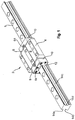
- FIG. 1 shows a linear roller bearing or linear roller bearing, which consists of a guide rail 1 and a guide carriage 2 according to the invention.
- This has a main body 4 with a side facing away from the guide rail 1 surface 6, are provided on the threaded holes for attaching a load.
- Front side of the main body 4 in the direction of travel of the carriage 2 front and rear two deflecting plates 8 are provided, which rest against the main body 4.
- two end caps 10 are provided which abut the baffles 8.
- two covers 12 are arranged, which are inserted into the respective end cap 10, and of which in FIG. 1 only one cover 12 is visible.
- At each end cap 10 there are up to four possible lubrication ports 64, two laterally, one at the front and one at the top.
- the guide rail 1 has - with respect to the direction of travel of the guide carriage 2 - two tracks 14a - 14d on both sides, wherein each two equidistant tracks 14a, 14b and 14c, 14d are each employed at 90 ° to each other.
- the carriage 2 can be supported in all directions, which are arranged transversely to the direction of travel.
- FIG. 2 shows an end face of the guide rail 1 and the main body 4 of the guide carriage 2 according to the invention in a cross section.
- the traversing direction of the guide carriage 2 is arranged perpendicular to the plane of the drawing.
- the main body 4 engages arcuately the guide rail. 1
- roller-shaped rolling elements or rollers 16a - 16d are provided in or on the main body 4 . Furthermore, four associated roller conveyors 18a-18d are shown. After the rollers 16a-16d have rolled along at least the entire length of the main body 4, they are deflected in one of the end caps 10 and then run back over a return area of the roller conveyor 18a-18d. In the rolling motion, the rollers 16a-16d move along a respective roller track insert 20a 20d of the main body 4 extending along the traveling direction and hardened for wear.
- rollers 16a - 16d extends a respective roller guide web 22a, 22b.
- FIG. 3 shows a circuit diagram of the lubricant supply of the guide carriage 2 according to the invention.
- the framed components are arranged in the interior of the guide carriage 2, while a piston distributor 25, a quick coupling 26 and an external check valve 28 in a (not shown in detail) towing device of the carriage 2 are added.
- a lubrication pump 30 is provided which conveys lubricant via a lubrication line 32 to one or both end caps 10 of the guide carriage 2.
- the piston distributor, the quick coupling 26 and the external check valve 28 are arranged.
- piston distributor 25 With regard to the piston distributor 25, reference is made to the document " Piston Manifolds, Metering Units for Single Line Lubrication Systems (Oil) "1-5001-EN from 2009 of the SKF Group taken and directed.
- Such piston distributor 25 can always clocked a certain amount of lubricant through clocked.
- a piston (not shown) is arranged in the interior of the piston distributor 25, which always sucks some lubricant from the lubricant line 32 against the conveying direction of the lubricant during its recurrent return movement due to the system.
- the external check valve 28 is provided in order to prevent that thereby the lubricant supply in the interior of the guide carriage 2 is partially discharged.
- the lubrication line 32 opens via the lubrication port 64 in a higher-level branch 34. Downstream of the branch 34, two internal non-return valves 55 prestressed by a respective compression spring 36 are provided.
- the two compression springs 36 of the two check valves 55 each span a ball 42 against a valve seat 39.
- a secondary branch 38 Downstream of each internal check valve 55, a secondary branch 38 is provided downstream of each sub-branch 38. Downstream of each sub-branch 38, a total of four orifices 40a-40d are provided in the four roller conveyors 18a-18d.
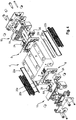
- FIG. 4 shows an exploded view of the carriage 2 according to the prior art, in which the branches 34, 38 according to FIG. 3 and two check valves 55 according to FIG. 6 or two check valves according to FIG. 7 or two check valves according to FIG. 8 to be built in.
- a pair of deflectors 24 are inserted on its side facing the main body 4, which rest against the associated deflecting plate 8.
- Each deflection piece 24, together with the deflecting plates 8, forms two crossed and nested deflection paths of the roller conveyors 18a-18d.
- FIGS. 5a and 5b show one of the two baffles 8 of the carriage 2 (see. FIG. 4 ) in different views.
- the two baffles 8 are clamped between the associated end cap 10 and the main body 4.
- FIG. 5b shows the outer side of the baffle 8, which rests against the respective end cap 10 and thus to the two associated deflection pieces 24 (see. FIG. 4 ).
- FIG. 5a shows the inner side of the baffle 8, which rests against the front side of the main body 4 (see. FIG. 4 ).
- the passage recess 52 of the baffle 8 forms the higher-level branch 34 (cf. FIG. 3 ).
- the lubricant is passed over two arcuate branching lubricant grooves 54 to the two sides of the baffle plate 8 and thus of the guide carriage 2.
- the lubricant grooves 54 are covered by the end face of the main body 4, whereby lubricant channels are formed.
- the two lubricant grooves 54 and lubricant channels respectively open into a through-passage 38 of the deflection plate 8.
- FIG. 6 shows a section of the outer side of the baffle 8 in the region of one of the two passage recesses 38, which simultaneously form a valve seat 38 of the respective internal check valve 55. Further shows FIG. 6 in an exploded view, the internal check valve 55, which is formed by the valve seat 38, the ball 42 and the compression spring 36. The compression spring 36 is supported on the associated deflection piece 24, of which a section is shown.
- the lubricant channel branches into two branch grooves 58.
- Each branch groove 58 opens at the respective mouth 40c, 40d into a roller track 18a-18d.
- the deflection piece 24 is stretched against the deflection plate 8 and thus closes the branch grooves 58, whereby branch channels are formed.
- the deflection piece 24 has corresponding sealing projections 60.
- FIG. 7 shows a closing body 142 and a compression spring 136 of a second embodiment of the internal check valve according to the invention.
- the closure member 142 is cup-shaped and has an approximately hemispherical portion which rests against the valve seat 38 in the closed state of the check valve (see. FIG. 6 ).
- the compression spring 136 immersed in sections in a recess of the closing body 142 a.
- the closing body 142 and the compression spring 136 are in the second embodiment of the internal check valve according to the invention between the baffle plate 8 and the deflection piece 24 with respect to the reference to FIG. 6 clamped manner shown.
- FIG. 8 shows a closing body 242 of a third embodiment of the internal check valve according to the invention.
- the closing body 242 is shaped circular cylindrical and consists of foam or elastomer with low Shore hardness. He was cut out of a semi-finished product by water jet cutting.
- the closing body 242 is elastic, so that a compression spring according to the first and the second embodiment can be omitted.
- the closing body 242 is between the baffle 8 and the deflection piece 24 according to FIG. 6 clamped.
- the surfaces of the closing body 242 are closed-cell or coated with an additional substance, so that it can not be soaked with lubricant and improved sealing effect is achieved.
- the circular cylinder top surface presses on a smaller bore. This has the advantage that inaccuracies can be compensated by module assembly between a receiving bore for the closing bodies 242 and flow opening.
- a carriage which can be moved to form a linear roller bearing on a guide rail.
- the carriage has four endless revolving rows of rollers which are guided in respective roller conveyors.
- the guide carriage has a central main body, at the two spaced apart in the travel direction end faces directly adjacent or spaced one end cap is arranged. In the end caps, the rows of roles are deflected.
- a branching lubricant line is provided between a provided on an outer side of at least one end cap lubricant inlet and the four rows of rollers or the four roller conveyors .
- two or four internal check valves are provided with a respective closing body whose opening direction corresponds to the conveying direction.
Landscapes
- Engineering & Computer Science (AREA)
- General Engineering & Computer Science (AREA)
- Mechanical Engineering (AREA)
- Bearings For Parts Moving Linearly (AREA)
Description
- Die Erfindung betrifft einen Führungswagen für ein Linearrollenlager gemäß dem Oberbegriff des Patentanspruchs 1.
- Führungswagen für Linearrollenlager ermöglichen unter hohen Lasten eine präzise geführte lineare Bewegung. Dazu verfährt der Führungswagen, an dem die Last angreift, entlang einer geraden Führungsschiene. Zur Reduzierung der Reibung bei gleichzeitig hohen übertragbaren Lasten laufen zwischen dem Führungswagen und der Führungsschiene meistens vier geschlossene bzw. endlose Reihen von Rollen in entsprechenden Rollenbahnen um. Die Führungsschiene wird von Führungswagen umgriffen, so dass eine Abstützung von Lasten in alle Richtungen möglich ist, die quer zur Verfahrrichtung gerichtet sind.
- Bei dem in der Druckschrift
DE10 2007 056 862 A1 gezeigten Führungswagen sind beidseitig der Führungsschiene jeweils zwei Reihen von Rollen vorgesehen, wodurch ein Abheben des Führungswagens von der Führungsschiene verhindert wird. Dabei sind so genannte Umlenkstücke im Innern des Führungswagens eingesetzt, die jeweils zur Umlenkung von zwei Rollenreihen dienen. Jeweils zwei Umlenkstücke sind gemeinsam in eine stirnseitige Endkappe des Führungswagens eingesetzt, von denen zwei vorgesehen sind. Die Umlenkstücke haben jeweils gekrümmte und bei der sogenannten O-Anordnung ineinander verschachtelte Umlenkbahnen, die jeweils einen Abschnitt einer Rollenbahn bilden. - Die Druckschrift
DE 10 2010 049 943 A1 offenbart ein Schmiersystem für derartige Führungswagen. Dabei wird der Führungswagen mit Schmiermittel versorgt, das über interne Kanäle zu Mündungen in die Rollenbahnen geführt wird, an denen die Rollen vorbei laufen. - Um ein Leerlaufen der Schmiermittelleitungen zu verhindern, wenn der Führungswagen und damit die Schmiermittelförderung stillstehen, schlägt die Druckschrift
DE 44 12 797 C2 eine Schmiermittelrückhaltevorrichtung vor, die als Rückschlagventil ausgebildet ist. Nachteilig daran ist, dass das Rückschlagventil an einer Stirnseite des Führungswagens und somit beabstandet zu den Rollenbahnen angeordnet ist. Dadurch verbleibt ein Abschnitt des Schiermittelleitung zwischen dem Rückschlagventil und der Rollenbahn, der leerlaufen kann, und der bei einem Wiederanfahren bzw. bei einem Neustart der Schmierung zunächst wieder gefüllt werden muss. - Die Druckschrift
DE 10 2010 049 944 A1 offenbart in der Nähe der Mündungen der Schmiermittelleitungen in die Rollenbahnen elastische Ventilklappen. Diese sind in einer so genannten Umlenkplatte ausgebildet, die zwischen der jeweiligen Endkappe und einem mittleren Hauptkörper des Führungswagens vorgesehen ist. Die Ventilklappen werden elastisch gebogen und geben eine Weg für Schmiermittel frei, wenn dieses und einen gegen die Ventilklappe gefördert wird. Dabei verbleibt auch bei geschlossener Ventilklappe ein U-förmiger Schlitz, der im bei einem Einsatz von dünnflüssiges Schmiermittel stets etwas Schmiermittel durchlässt. - Die Druckschrift
EP 2 094 984 B1 offenbart als Schmiermittelrückhaltung Ventile in der Nähe der Rollenbahn. Die Ventile sind im Innern der Endkappe angeordnet, die stirnseitig an dem Führungswagen angesetzt sind. Die Ventile bestehen aus elastisch biegbaren lappenartigen Elementen, die in Förderrichtung des Schmiermittels einen Schlitz freigeben, der in Gegenrichtung zugedrückt wird. - Aus der
DE 103 32 922 A1 ist ein Führungswagen mit den Merkmalen des Oberbegriffs des Anspruchs 1 bekannt, dessen Ventilkörper einstückig mit der Umlenkplatte ausgebildet ist. - Nachteilig an den letztgenannten Führungswagen ist, dass ihre Schmiermittelrückhaltevorrichtungen bei dünnflüssigem Schmiermittel nicht ausreichend dicht sind. Weiterhin haben derartige Schmiermittelrückhaltevorrichtungen Fertigungstoleranzen, die ein ungleiches Öffnungsverhalten zur Folge haben. Insbesondere wenn die benötigten Schmiermittelmenge minimiert werden sollen, ist ein gleichmäßiges Verhalten aller Schmiermittelrückhaltevorrichtungen wichtig, damit eine gleichmäßige Versorgung aller Rollenbahnen mit Schmiermittel gewährleistet ist.
- Dem entsprechend liegt der Erfindung die Aufgabe zu Grunde, einen Führungswagen für ein Linearrollenlager zu schaffen, dessen Schmiermittelrückhaltevorrichtungen verbessert sind.
- Diese Aufgabe wird gelöst durch einen Führungswagen für ein Linearrollenlager mit den Merkmalen des Patentanspruchs 1.
- Der beanspruchte Führungswagen kann zur Bildung eines Linearrollenlagers auf einer Führungsschiene verfahren werden. Der Führungswagen hat vier endlos umlaufenden Reihen von Rollen und einen mittleren Hauptkörper, an dessen Stirnseiten direkt anliegend oder beabstandet jeweils eine Endkappe angeordnet ist, in denen die Reihen von Rollen umgelenkt werden. Zwischen einem an einer Außenseite der Endkappe vorgesehenen Schmiermitteleingang bzw. Schmiermittelanschluss und den Reihen von Rollen bzw. ihren Rollenbahnen ist eine verzweigende Schmiermittelleitung vorgesehen. Erfindungsgemäß sind in der Schmiermittelleitung im Innern der Endkappe oder zwischen der Endkappe und dem Hauptkörper mehrere interne Rückschlagventile mit einem jeweiligen Schließkörper vorgesehen. Die Öffnungsrichtung der Rückschlagventile entspricht der Förderrichtung des Schmiermittels. Derartige Ventile mit Schließkörper weisen eine verbesserte Dichtigkeit auf da ihr Schließkörper an einen Ventilsitz des Rückschlagventils angepasst werden kann. Vorzugsweise sind die Rückschlagventile und ihre Schließkörper rotationssymmetrisch. Die Dichtung ist dann kreisförmig und daher passgenauer aus bei Schmiermittelrückhaltevorrichtungen gemäß dem Stand der Technik.
- Bei einem insbesondere für kurze Hübe bzw. Verfahrwege geeigneten Führungswagen hat jede Rollenbahn beidseitig eine Mündung für Schmiermittel. Dann sind auch in einer zweiten im Wesentlichen gespiegelten Endkappe - wie die erste Endkappe - eine Schmiermittelleitung und die erfindungsgemäßen Rückschlagventile vorgesehen.
- Weitere vorteilhafte Ausgestaltungen der Erfindung sind in den abhängigen Patentansprüchen beschrieben.
- Bei einem erfindungsgemäßen Führungswagens sind in der Schmiermittelleitung eine erste Verzweigung und - in Förderrichtung betrachtet - dahinter zwei zweite Verzweigungen und zwei interne Rückschlagventile vorgesehen. Diese sind - in Förderrichtung betrachtet - hinter der ersten Verzweigung und vor den zweiten Verzweigungen angeordnet. Da somit ein Rückschlagventil in Wirkverbindung mit zwei Mündungen steht, ist der vorrichtungstechnische Aufwand minimiert.
- Bei dem insbesondere für kurze Hübe bzw. Verfahrwege geeigneten erfindungsgemäßen Führungswagen sind die Rückschlagventile der zweiten Endkappe wie in der ersten Endkappe angeordnet.
- Bei einem erfindungsgemäßen Führungswagen mit sich kreuzenden Rollenbahnen (O-Anordnung) liegt an jeder Stirnseite des Hauptkörpers eine Umlenkplatte an, und an der vom Hauptkörper abgewandten Außenseite jeder Umlenkplatte liegt ein Paar von Umlenkstücken an. Diese sind im Innern der ersten Endkappe aufgenommen und können miteinander verbunden sein. Dann wird es besonders bevorzugt, wenn die übergeordnete Verzweigung und die beiden untergeordneten Verzweigungen an der Umlenkplatte gebildet sind, wobei jedes Rückschlagventil durch eine Wirkverbindung zwischen der Umlenkplatte und einem jeweiligen Umlenkstück gebildet ist.
- Bei dem insbesondere für kurze Hübe bzw. Verfahrwege geeigneten erfindungsgemäßen Führungswagen ist diese Anordnung auch an der zweiten gegenüber liegenden Seite des Führungswagens vorgesehen.
- Bei einer ersten Alternative der Erfindung hat jedes interne Rückschlagventil eine Druckfeder, über die der Schließkörper gegen einen an der Umlenkplatte gebildeten Ventilsitz vorgespannt ist. Die Druckfeder stützt sich am jeweiligen Umlenkstück ab.
- Dabei wird es bevorzugt, wenn der Schließkörper becherartig geformt ist und mit einer gewölbten Außenseite am jeweiligen Ventilsitz anliegt. Die Druckfeder taucht in eine - vorzugsweise konzentrische - Ausnehmung des Schließkörpers ein. Damit ist keine Führung des Schließkörpers und der Druckfeder nötig.
- Bei einer zweiten vorrichtungstechnisch einfachen Alternative der Erfindung hat der Schließkörper eine kreiszylindrische oder kegelige Form und ist elastisch. Weiterhin ist der Schließkörper zwischen Umlenkplatte und Umlenkstück eingespannt.
- Wenn dabei der Schließkörper aus einem Schaumstoff oder einem Elastomer mit niedriger Shorehärte besteht und kreiszylindrisch ist, können aus einem ebenen Halbzeug viele Schließkörper über Wasserstrahlschneiden gefertigt werden.
- Die Oberflächen der Schließkörper können dabei zusätzlich durch einen zusätzlichen Stoff beschichtetet oder kaschiert sein um die Dichtwirkung zu verbessern.
- Wenn der Schaumstoff geschlossene Zellen hat, wird ein Vollsaugen des Schließkörpers mit Schmiermittel vermieden.
- Bei dem insbesondere für kurze Hübe bzw. Verfahrwege geeigneten erfindungsgemäßen Führungswagen sind auch die Rückschlagventile der zweiten Endkappe gemäß der ersten oder zweiten oben beschriebenen Weiterbildung ausgestaltet.
- In Förderrichtung betrachtet vor dem ersten Schmiermitteleingang kann ein erster Kolbenverteiler oder ein erstes Dosierventil vorgesehen sein. Damit wird in regelmäßigen Zeitabständen eine vorbestimmte Menge Schmiermittel von einer zentralen Schmiermittelpumpe zum Führungswagen durchgelassen.
- Bei dem insbesondere für kurze Hübe bzw. Verfahrwege geeigneten erfindungsgemäßen Führungswagen ist auch vor dem zweiten Schmiermitteleingang ein Kolbenverteiler bzw. Dosierventil angeordnet.
- Mehrere Kolbenverteiler oder Dosierventile können in einer konstruktiven Einheit oder in einem gemeinsamen Gehäuse gruppiert sein.
- Da derartige Kolbenverteiler einen Rückzug des Schmiermittels erzeugen, wird ein externes Rückschlagventil bevorzugt, das verhindert, dass die Schmiermitteleitung gegen die Förderrichtung abschnittsweise geleert (leergezogen) wird. Das externe Rückschlagventil wird zwischen dem Kolbenverteiler und dem Schmiermitteleingang ein angeordnet. Seine Öffnungsrichtung entspricht der Förderrichtung.
- Bei dem insbesondere für kurze Hübe bzw. Verfahrwege geeigneten erfindungsgemäßen Führungswagen ist auch vor dem zweiten Schmiermitteleingang ein zweites externes Rückschlagventil angeordnet.
- Im Folgenden werden anhand der Figuren verschiede Ausführungsbeispiele der Erfindung detailliert beschrieben. Es zeigen
-
Figur 1 ein erstes Ausführungsbeispiel eines erfindungsgemäßen Führungswagens mit einer Führungsschiene in einer perspektivischen Darstellung; -
Figur 2 das erste Ausführungsbeispiel des Führungswagens mit Führungsschiene in einer geschnittenen Ansicht; -
Figur 3 einen Schaltplan der Schmierstoffversorgung des ersten Ausführungsbeispiels; -
Figur 4 eine Explosionszeichnung eines Führungswagens gemäß dem Stand der Technik; -
Figur 5a und 5b eine Umlenkplatte des ersten Ausführungsbeispiels des erfindungsgemäßen Führungswagens; -
Figur 6 eine Umlenkplatte und ein Umlenkstück mit einem internen Rückschlagventil des ersten Ausführungsbeispiels in einer Explosionszeichnung; -
Figur 7 wesentliche Komponenten eines zweiten Ausführungsbeispiels des internen Rückschlagventils; und -
Figur 8 einen Schließkörper eines dritten Ausführungsbeispiels des internen Rückschlagventils. -
Figur 1 zeigt ein Linearwälzlager bzw. Linearrollenlager, das aus einer Führungsschiene 1 und einem erfindungsgemäßen Führungswagen 2 besteht. Dieser hat einen Hauptkörper 4 mit einer von der Führungsschiene 1 abgewandten Oberfläche 6, an der Gewindelöcher zur Befestigung einer Last vorgesehen sind. Stirnseitig am Hauptkörper 4 in Verfahrrichtung des Führungswagens 2 vorne und hinten sind zwei Umlenkplatten 8 vorgesehen, die am Hauptkörper 4 anliegen. Ebenfalls stirnseitig am Führungswagen 2 sind zwei Endkappen 10 vorgesehen, die an den Umlenkplatten 8 anliegen. An den äußersten Stirnflächen des Führungswagens 2 sind zwei Abdeckungen 12 angeordnet, die in die jeweilige Endkappe 10 eingesetzt sind, und von denen inFigur 1 nur eine Abdeckung 12 sichtbar ist. An jeder Endkappe 10 befinden sich bis zu vier mögliche Schmieranschlüsse 64, zwei seitlich, einer stirnseitig und einer oben. - Die Führungsschiene 1 hat - mit Bezug zur Verfahrrichtung des Führungswagens 2 - beidseitig jeweils zwei Laufbahnen 14a - 14d, wobei jeweils zwei gleichseitig angeordneten Laufbahnen 14a, 14b bzw. 14c, 14d jeweils um 90° zueinander angestellt sind. Dadurch kann sich der Führungswagen 2 in allen Richtungen, die quer zur Verfahrrichtung angeordnet sind, abstützen.
-
Figur 2 zeigt eine Stirnseite der Führungsschiene 1 und den Hauptkörper 4 des erfindungsgemäßen Führungswagens 2 in einem Querschnitt. Dabei ist die Verfahrrichtung des Führungswagens 2 senkrecht zur Zeichenebene angeordnet. Der Hauptkörper 4 umgreift bogenförmig die Führungsschiene 1. - Im bzw. am Hauptkörper 4 sind vier umlaufende bzw. endlose Reihen von rollenförmigen Wälzkörpern bzw. Rollen 16a - 16d vorgesehen. Weiterhin sind vier zugeordnete Rollenbahnen 18a - 18d dargestellt. Nachdem sich die Rollen 16a - 16d entlang zumindest der gesamten Länge des Hauptkörpers 4 abgewälzt haben, werden sie in einer der Endkappen 10 umgelenkt und laufen dann über einen Rücklaufbereich der Rollenbahn 18a - 18d zurück. Bei der abwälzenden Bewegung bewegen sich die Rollen 16a - 16d entlang einer jeweiligen Rollenbahneinlage 20a 20d des Hauptkörpers 4, die sich entlang der Verfahrrichtung erstrecken, und die aus Verschleißgründen gehärtet sind.
- Ebenfalls in Verfahrrichtung entlang den an der Führungsschiene 1 anliegenden Reihen von Rollen 16a - 16d erstreckt sich ein jeweiliger Rollenführungssteg 22a, 22b.
-
Figur 3 zeigt einen Schaltplan der Schmierstoffversorgung des erfindungsgemäßen Führungswagens 2. Die eingerahmten Komponenten sind im Innern des Führungswagens 2 angeordnet, während ein Kolbenverteiler 25, eine Schnellkupplung 26 und ein externes Rückschlagventil 28 in einer (nicht näher gezeigten) Schleppvorrichtung des Führungswagens 2 aufgenommen sind. Dem gegenüber ortsfest ist eine Schmierpumpe 30 vorgesehen, die Schmiermittel über eine Schmierleitung 32 zu einer oder zu beiden Endkappen 10 des Führungswagens 2 fördert. In der Schmierleitung 32 sind der Kolbenverteiler, die Schnellkupplung 26 und das externe Rückschlagventil 28 angeordnet. - Bezüglich des Kolbenverteilers 25 wird auf die Druckschrift "Kolbenverteiler, Dosiereinheiten für Einleitungs-Verbrauchsschmieranlagen (Öl)" 1-5001-DE von 2009 der SKF Gruppe Bezug genommen und verwiesen. Derartige Kolbenverteiler 25 lassen zeitlich getaktet stets eine gewisse Schmiermittelmenge durch. Dazu ist im Innern des Kolbenverteilers 25 ein (nicht gezeigter) Kolben angeordnet, der bei seiner wiederkehrenden Rückbewegung systembedingt stets etwas Schmiermittel aus der Schmiermittelleitung 32 gegen die Förderrichtung des Schmiermittels ansaugt. Um zu verhindern, dass dadurch die Schmiermittelversorgung im Innern des Führungswagens 2 abschnittsweise entleert wird, ist das externe Rückschlagventil 28 vorgesehen.
- Im Innern des Führungswagens 2 ist erfindungsgemäß entweder an dessen einen oder an beiden Stirnseiten des Hauptkörpers 4 die in
Figur 3 eingerahmte Anordnung innerhalb der jeweiligen Endkappe 10 vorgesehen. Die Schmierleitung 32 mündet über den Schmieranschluss 64 in einer übergeordneten Verzweigung 34. Stromab der Verzweigung 34 sind zwei durch eine jeweilige Druckfeder 36 vorgespannte interne Rückschlagventile 55 vorgesehen. Die beiden Druckfedern 36 der beiden Rückschlagventile 55 spannen jeweils eine Kugel 42 gegen einen Ventilsitz 39. - Stromab jedes internen Rückschlagventils 55 ist eine untergeordnete Verzweigung 38 vorgesehen. Stromab jeder untergeordneten Verzweigung 38 sind insgesamt vier Mündungen 40a - 40d in die vier Rollenbahnen 18a - 18d vorgesehen.
-
Figur 4 zeigt eine Explosionszeichnung des Führungswagens 2 gemäß dem Stand der Technik, in den die Verzweigungen 34, 38 gemäßFigur 3 und zwei Rückschlagventile 55 gemäßFigur 6 oder zwei Rückschlagventile gemäßFigur 7 oder zwei Rückschlagventile gemäßFigur 8 eingebaut werden. In jede Endkappe 10 sind an ihrer dem Hauptkörper 4 zugewandten Seite ein Paar von Umlenkstücken 24 eingesetzt, die an der zugeordneten Umlenkplatte 8 anliegen. Jedes Umlenkstück 24 bildet zusammen mit den Umlenkplatten 8 zwei gekreuzte und ineinander verschachtelte Umlenkbahnen der Rollenbahnen 18a - 18d. Weiterhin wird bzgl. des Grundaufbaus des Führungswagens 2 auf die DruckschriftDE 10 2010 049 944 A1 Bezug genommen und verwiesen. -
Figuren 5a und 5b zeigen eine der beiden Umlenkplatten 8 des Führungswagens 2 (vgl.Figur 4 ) in verschiedenen Ansichten. Wie mit Bezug zurFigur 1 erläutert wurde, sind die beiden Umlenkplatten 8 zwischen der zugeordneten Endkappe 10 und dem Hauptkörper 4 eingespannt.Figur 5b zeigt die äußere Seite der Umlenkplatte 8, die an der jeweiligen Endkappe 10 und damit an den beiden zugeordneten Umlenkstücken 24 anliegt (vgl.Figur 4 ). Über eine mittlere Durchgangsausnehmung 52 der Umlenkplatte 8 wird das Schmiermittel zugeführt. -
Figur 5a zeigt die innere Seite der Umlenkplatte 8, die an der Stirnseite an dem Hauptkörper 4 anliegt (vgl.Figur 4 ). Die Durchgangsausnehmung 52 der Umlenkplatte 8 bildet die übergeordnete Verzweigung 34 (vgl.Figur 3 ). Von dort wird das Schmiermittel über zwei bogenförmig verzweigende Schmiermittelnuten 54 zu den beiden Seiten der Umlenkplatte 8 und damit des Führungswagens 2 geleitet. Die Schmiermittelnuten 54 werden durch die Stirnseite des Hauptkörpers 4 abgedeckt, wodurch Schmiermittelkanäle gebildet sind. Die beiden Schmiermittelnuten 54 bzw. Schmiermittelkanäle münden jeweils in eine Durchgangsausnehmung 38 der Umlenkplatte 8. -
Figur 6 zeigt einen Ausschnitt der äußeren Seite der Umlenkplatte 8 im Bereich einer der beiden Durchgangsausnehmungen 38, die gleichzeitig einen Ventilsitz 38 des jeweiligen internen Rückschlagventils 55 bilden. Weiterhin zeigtFigur 6 in einer Explosionszeichnung das interne Rückschlagventil 55, das von dem Ventilsitz 38, der Kugel 42 und der Druckfeder 36 gebildet ist. Die Druckfeder 36 stützt sich an dem zugeordneten Umlenkstück 24 ab, von dem ein Ausschnitt gezeigt ist. - In Förderrichtung hinter dem Rückschlagventil 55 verzweigt der Schmiermittelkanal in zwei Zweignuten 58. Jede Zweignut 58 mündet an der jeweiligen Mündung 40c, 40d in eine Rollenbahn 18a - 18d. Das Umlenkstück 24 ist gegen die Umlenkplatte 8 gespannt und schließt so die Zweignuten 58, wodurch Zweigkanäle gebildet sind. Dabei hat das Umlenkstück 24 entsprechende Dichtvorsprünge 60.
-
Figur 7 zeigt einen Schließkörper 142 und eine Druckfeder 136 eines zweiten Ausführungsbeispiels des erfindungsgemäßen internen Rückschlagventils. Der Schließkörper 142 ist becherartig und hat einen etwa halbkugelförmigen Abschnitt, der im geschlossenen Zustand des Rückschlagventils an dem Ventilsitz 38 anliegt (vgl.Figur 6 ). Die Druckfeder 136 taucht abschnittsweise in eine Ausnehmung des Schließkörpers 142 ein. Der Schließkörper 142 und die Druckfeder 136 werden beim zweiten Ausführungsbeispiel des erfindungsgemäßen internen Rückschlagventils zwischen die Umlenkplatte 8 und das Umlenkstück 24 auf die mit Bezug zurFigur 6 dargestellten Weise eingespannt. -
Figur 8 zeigt einen Schließkörper 242 eines dritten Ausführungsbeispiels des erfindungsgemäßen internen Rückschlagventils. Der Schließkörper 242 ist kreiszylindrisch geformt und besteht aus Schaumstoff oder Elastomer mit niedriger Shorehärte. Er wurde durch Wasserstrahlschneiden aus einem Halbzeug herausgetrennt. Der Schließkörper 242 ist elastisch, so dass eine Druckfeder gemäß dem ersten und dem zweiten Ausführungsbeispiel entfallen kann. Der Schließkörper 242 wird zwischen die Umlenkplatte 8 und das Umlenkstück 24 gemäßFigur 6 eingespannt. Die Oberflächen des Schließkörpers 242 sind geschlossenzellig oder mit einem zusätzlichen Stoff beschichtet, so dass er sich nicht mit Schmiermittel vollsaugen kann und Verbesserung der Dichtwirkung erzielt wird. - Bei Schließkörpern 242 aus Schaumstoff oder Elastomeren presst die kreisförmige Zylinderdeckfläche auf eine kleinere Bohrung ab. Das hat den Vorteil, dass Ungenauigkeiten durch Baugruppenmontage zwischen einer Aufnahmebohrung für den Schließkörpern 242 und Durchflussöffnung ausgeglichen werden können.
- Offenbart ist ein Führungswagen, der zur Bildung eines Linearrollenlagers auf einer Führungsschiene verfahren werden kann. Der Führungswagen hat vier endlos umlaufenden Reihen von Rollen, die in jeweiligen Rollenbahnen geführt sind. Der Führungswagen hat einen mittleren Hauptkörper, an dessen beiden in Verfahrrichtung zueinander beabstandeten Stirnseiten direkt anliegend oder beabstandet jeweils eine Endkappe angeordnet ist. In den Endkappen werden die Reihen von Rollen umgelenkt. Zwischen einem an einer Außenseite zumindest einer Endkappe vorgesehenen Schmiermitteleingang und den vier Reihen von Rollen bzw. den vier Rollenbahnen ist eine verzweigende Schmiermittelleitung vorgesehen. In der Schmiermittelleitung im Innern der Endkappe oder zwischen der Endkappe und dem Hauptkörper sind zwei oder vier interne Rückschlagventile mit einem jeweiligen Schließkörper vorgesehen, deren Öffnungsrichtung der Förderrichtung entspricht.
-
- 1
- Führungsschiene
- 2
- Führungswagen
- 4
- Hauptkörper
- 6
- Oberfläche
- 8
- Umlenkplatte
- 10
- Endkappe
- 12
- Abdeckung
- 14a, 14b, 14c, 14d
- Laufbahn
- 16a, 16b, 16c, 16d
- Rolle
- 18a, 18b, 18c, 18d
- Rollenbahn
- 20a, 20b, 20c, 20d
- Rollenbahneinlage
- 22a, 22b
- Rollenführungssteg
- 24
- Umlenkstück
- 25
- Kolbenverteiler
- 26
- Schnellkupplung
- 28
- externes Rückschlagventil
- 30
- Schmierpumpe
- 32
- Schmierleitung
- 34
- übergeordnete Verzweigung
- 36; 136
- Druckfede
- 38
- untergeordnete Verzweigung / Ventilsitz/ Durchgangsausnehmung
- 40a, 40b, 40c, 40d
- Mündung
- 42
- Kugel
- 52
- Durchgangsausnehmung
- 54
- Schmiermittelnut
- 55
- internes Rückschlagventil
- 58
- Zweignut
- 60
- Dichtvorsprung
- 64
- Schmieranschluss
- 142
- becherartiger Schließkörper
- 242
- Schließkörper aus Schaumstoff
Claims (6)
- Führungswagen, der zur Bildung eines Linearrollenlagers auf einer Führungsschiene (1) verfahrbar ist, mit vier endlos umlaufenden Reihen von Rollen (16a - 16d) und mit einem mittleren Hauptkörper (4), an dessen Stirnseiten Endkappen (10) angeordnet sind, in denen die Reihen von Rollen (16a - 16d) umgelenkt sind, wobei zwischen einem an einer Außenseite einer Endkappe (10) vorgesehenen Schmiermitteleingang (64) und den Reihen von Rollen (16a - 16d) eine verzweigende Schmiermittelleitung vorgesehen ist, wobei in der Schmiermittelleitung im Innern der Endkappe (10) oder zwischen der Endkappe (10) und dem Hauptkörper (4) mehrere interne Rückschlagventile (55) mit einem jeweiligen Schließkörper (42; 142; 242) angeordnet sind,
wobei in der Schmiermittelleitung eine übergeordnete Verzweigung (34) und in Förderrichtung dahinter zwei untergeordneten Verzweigungen (38) und zwei interne Rückschlagventile (55) vorgesehen sind, die in Förderrichtung hinter der übergeordneten Verzweigung (34) und in Förderrichtung vor den untergeordneten Verzweigungen (38) angeordnet sind,
wobei an jeder Stirnseite des Hauptkörpers (4) eine Umlenkplatte (8) anliegt, an der die Verzweigungen (34, 38) gebildet sind, und wobei an der vom Hauptkörper (4) abgewandten Außenseite jeder Umlenkplatte (8) ein Paar von Umlenkstücken (24) anliegt, die im Innern der jeweiligen Endkappe (10) aufgenommen sind,
wobei die beiden internen Rückschlagventile (55) zwischen der Umlenkplatte (8) und einem jeweiligen Umlenkstück (24) gebildet sind,
dadurch gekennzeichnet, dass gemäß einer ersten Alternative jedes interne Rückschlagventil (55) eine Druckfeder (36; 136) hat, über die der Schließkörper (42; 142; 242) gegen einen an der Umlenkplatte (8) gebildeten Ventilsitz (38) vorgespannt ist, und wobei sich die beiden Druckfedern (36; 136) am jeweiligen Umlenkstück (24) abstützen,
wobei gemäß einer zweiten Alternative mit jedes interne Rückschlagventil (55) einen Schließkörper (242) kreiszylindrischer oder kegeliger Form hat, elastisch ist und zwischen der Umlenkplatte (8) und dem jeweiligen Umlenkstück (24) eingespannt ist. - Führungswagen nach Anspruch 1, wobei der Schließkörper (142) becherartig geformt ist und mit einer Außenseite am jeweiligen Ventilsitz (38) anliegt, und wobei die Druckfeder (136) in eine Ausnehmung des Schließkörpers (142) eintaucht.
- Führungswagen nach Anspruch 1, wobei der Schließkörper (242) aus einem Schaumstoff oder Elastomer gefertigt ist.
- Führungswagen nach Anspruch 3, wobei die Oberflächen des Schließkörpers geschlossene Zellen sind oder zusätzlichen mit einem Stoff beschichtet sind.
- Führungswagen nach einem der vorhergehenden Ansprüche, wobei in Förderrichtung vor dem Schmiermitteleingang (64) ein Kolbenverteiler (25) oder ein Dosierventil vorgesehen ist.
- Führungswagen nach Anspruch 5, wobei zwischen dem Kolbenverteiler (25) oder dem Dosierventil und dem Schmiermitteleingang (64) ein externes Rückschlagventil (28) angeordnet ist.
Applications Claiming Priority (1)
| Application Number | Priority Date | Filing Date | Title |
|---|---|---|---|
| DE102012222397.5A DE102012222397A1 (de) | 2012-12-06 | 2012-12-06 | Führungswagen |
Publications (2)
| Publication Number | Publication Date |
|---|---|
| EP2740957A1 EP2740957A1 (de) | 2014-06-11 |
| EP2740957B1 true EP2740957B1 (de) | 2016-03-16 |
Family
ID=49554083
Family Applications (1)
| Application Number | Title | Priority Date | Filing Date |
|---|---|---|---|
| EP13192039.9A Not-in-force EP2740957B1 (de) | 2012-12-06 | 2013-11-08 | Führungswagen |
Country Status (4)
| Country | Link |
|---|---|
| US (1) | US9062716B2 (de) |
| EP (1) | EP2740957B1 (de) |
| CN (1) | CN103851080B (de) |
| DE (1) | DE102012222397A1 (de) |
Families Citing this family (6)
| Publication number | Priority date | Publication date | Assignee | Title |
|---|---|---|---|---|
| JP6710543B2 (ja) * | 2016-03-03 | 2020-06-17 | 日本トムソン株式会社 | 直動案内ユニット |
| JP6494692B2 (ja) * | 2017-05-31 | 2019-04-03 | Thk株式会社 | 運動案内装置 |
| US10837540B2 (en) * | 2017-09-19 | 2020-11-17 | Applied Materials Israel Ltd. | Lubrication system and a method for lubricating a transmission system component |
| DE102018129652A1 (de) * | 2018-11-26 | 2020-05-28 | Schaeffler Technologies AG & Co. KG | Führungswagen einer Linearführung und Verfahren zur Herstellung eines Kopfstücks eines Führungswagens |
| CN116276140A (zh) * | 2022-11-24 | 2023-06-23 | 江苏胜德龙机电科技有限公司 | 一种机床用滑动导轨 |
| GB2635657A (en) * | 2023-11-07 | 2025-05-28 | Rigging Projects Ltd | Traveller car |
Family Cites Families (16)
| Publication number | Priority date | Publication date | Assignee | Title |
|---|---|---|---|---|
| DE2931383A1 (de) * | 1979-08-02 | 1981-02-19 | Polysius Ag | Hydrodynamisches lager |
| DE4141038A1 (de) * | 1991-12-12 | 1993-06-17 | Schaeffler Waelzlager Kg | Abstreifereinheit fuer ein lagerelement |
| DE4210299C2 (de) * | 1992-03-28 | 1995-09-28 | Schaeffler Waelzlager Kg | Wälzlager für eine geradlinige Bewegung |
| DE4238910A1 (de) * | 1992-11-19 | 1994-05-26 | Schaeffler Waelzlager Kg | Abstreifereinheit für ein Linearwälzlagerelement |
| US5584581A (en) * | 1993-09-10 | 1996-12-17 | Deutsche Star Gmbh | Linear guiding device |
| DE4412797C2 (de) | 1994-04-14 | 2002-03-07 | Schaeffler Waelzlager Ohg | Lagerelement mit einer Schmiervorrichtung |
| DE19647937B4 (de) * | 1996-11-20 | 2008-06-26 | Schaeffler Kg | Wälzlager |
| DE19753104A1 (de) * | 1997-11-29 | 1999-06-02 | Schaeffler Waelzlager Ohg | Schmiervorrichtung für ein Linearwälzlager |
| DE10332922A1 (de) * | 2003-07-19 | 2005-02-03 | Ina-Schaeffler Kg | Führungswagen eines Linearwälzlagers |
| DE102006055196A1 (de) | 2006-11-23 | 2008-05-29 | Schaeffler Kg | Linearführungseinheit |
| JP4838179B2 (ja) * | 2007-03-16 | 2011-12-14 | 日本トムソン株式会社 | 直動案内ユニット |
| DE102007013945A1 (de) * | 2007-03-23 | 2008-09-25 | Schaeffler Kg | Schmiervorrichtung für ein Linearwälzlager |
| DE102007056862B4 (de) * | 2007-11-26 | 2023-01-26 | Robert Bosch Gmbh | Linearrollenlager mit Umlenkstück |
| CN101590603B (zh) * | 2009-07-08 | 2011-01-05 | 路文忠 | 精密静压直线导轨 |
| DE102010049943A1 (de) | 2010-10-28 | 2012-05-03 | Robert Bosch Gmbh | Führungswagen mit Schmier- und Bypasskanal |
| DE102010049944A1 (de) | 2010-10-28 | 2012-05-03 | Robert Bosch Gmbh | Führungswagen mit Schmierventil |
-
2012
- 2012-12-06 DE DE102012222397.5A patent/DE102012222397A1/de not_active Withdrawn
-
2013
- 2013-11-08 EP EP13192039.9A patent/EP2740957B1/de not_active Not-in-force
- 2013-11-12 US US14/077,970 patent/US9062716B2/en not_active Expired - Fee Related
- 2013-12-05 CN CN201310643839.2A patent/CN103851080B/zh not_active Expired - Fee Related
Also Published As
| Publication number | Publication date |
|---|---|
| CN103851080A (zh) | 2014-06-11 |
| US20140161377A1 (en) | 2014-06-12 |
| EP2740957A1 (de) | 2014-06-11 |
| DE102012222397A1 (de) | 2014-06-26 |
| US9062716B2 (en) | 2015-06-23 |
| CN103851080B (zh) | 2018-09-04 |
Similar Documents
| Publication | Publication Date | Title |
|---|---|---|
| DE102007056862B4 (de) | Linearrollenlager mit Umlenkstück | |
| EP2740957A1 (de) | Führungswagen | |
| DE4395740C1 (de) | Linearlagerelement | |
| EP1676040B1 (de) | Führungswagen eines linearw älzlagers | |
| EP2655909B1 (de) | Führungswagen mit schmier- und bypasskanal | |
| EP2655908B1 (de) | Führungswagen mit schmierventil | |
| EP2041443A2 (de) | Laufrollenführung | |
| EP2518349A2 (de) | Konzept zum Schmieren eines Führungswagens | |
| DE102005054082B4 (de) | Käfig für ein Wälzlager | |
| EP3371471B1 (de) | Wälzkörper-umlaufschuh für ein linearwälzlager mit einem vorsatzelement zur langzeitschmierung | |
| DE102007056858B4 (de) | Zweiteiliges Rückführrohr für ein Linearwälzlager | |
| DE102007056860B4 (de) | Linearwälzlager mit gemeinsamen Verschlusselementen für Wälzkörpereinfüllkanäle | |
| DE102008052083A1 (de) | Linearwälzlager mit Schmierkanal | |
| DE102012223932A1 (de) | Führungswagen | |
| EP1303706B1 (de) | Linearwälzlager | |
| EP4413275B1 (de) | Führungswagen einer linearführung | |
| DE102011017749B4 (de) | Konzept für einen Führungswagen einer Linearführung | |
| DE102012213222A1 (de) | Führungswagen für ein Linearrollenlager | |
| DE10317049A1 (de) | Linearkugellager | |
| DE102005019286A1 (de) | Abstandhalter für Wälzkörper | |
| DE102006040981A1 (de) | Linearführungseinrichtung | |
| DE102007056878A1 (de) | Linearwälzlager mit luftdichtem Schmierkanal | |
| DE202005020755U1 (de) | Linearführung mit einer Umlaufeinrichtung | |
| DE102005008498A1 (de) | Linearführung mit einer Umlaufeinrichtung | |
| WO2009065741A1 (de) | Wälzlagerkäfig für längsführungen |
Legal Events
| Date | Code | Title | Description |
|---|---|---|---|
| PUAI | Public reference made under article 153(3) epc to a published international application that has entered the european phase |
Free format text: ORIGINAL CODE: 0009012 |
|
| 17P | Request for examination filed |
Effective date: 20131108 |
|
| AK | Designated contracting states |
Kind code of ref document: A1 Designated state(s): AL AT BE BG CH CY CZ DE DK EE ES FI FR GB GR HR HU IE IS IT LI LT LU LV MC MK MT NL NO PL PT RO RS SE SI SK SM TR |
|
| AX | Request for extension of the european patent |
Extension state: BA ME |
|
| R17P | Request for examination filed (corrected) |
Effective date: 20141211 |
|
| RBV | Designated contracting states (corrected) |
Designated state(s): AL AT BE BG CH CY CZ DE DK EE ES FI FR GB GR HR HU IE IS IT LI LT LU LV MC MK MT NL NO PL PT RO RS SE SI SK SM TR |
|
| GRAP | Despatch of communication of intention to grant a patent |
Free format text: ORIGINAL CODE: EPIDOSNIGR1 |
|
| RIC1 | Information provided on ipc code assigned before grant |
Ipc: F16C 29/06 20060101ALI20151002BHEP Ipc: F16C 33/66 20060101AFI20151002BHEP |
|
| INTG | Intention to grant announced |
Effective date: 20151105 |
|
| GRAS | Grant fee paid |
Free format text: ORIGINAL CODE: EPIDOSNIGR3 |
|
| GRAA | (expected) grant |
Free format text: ORIGINAL CODE: 0009210 |
|
| AK | Designated contracting states |
Kind code of ref document: B1 Designated state(s): AL AT BE BG CH CY CZ DE DK EE ES FI FR GB GR HR HU IE IS IT LI LT LU LV MC MK MT NL NO PL PT RO RS SE SI SK SM TR |
|
| REG | Reference to a national code |
Ref country code: GB Ref legal event code: FG4D Free format text: NOT ENGLISH |
|
| REG | Reference to a national code |
Ref country code: CH Ref legal event code: EP |
|
| REG | Reference to a national code |
Ref country code: IE Ref legal event code: FG4D Free format text: LANGUAGE OF EP DOCUMENT: GERMAN |
|
| REG | Reference to a national code |
Ref country code: AT Ref legal event code: REF Ref document number: 781510 Country of ref document: AT Kind code of ref document: T Effective date: 20160415 |
|
| REG | Reference to a national code |
Ref country code: DE Ref legal event code: R096 Ref document number: 502013002189 Country of ref document: DE |
|
| REG | Reference to a national code |
Ref country code: NL Ref legal event code: MP Effective date: 20160316 |
|
| REG | Reference to a national code |
Ref country code: LT Ref legal event code: MG4D |
|
| PG25 | Lapsed in a contracting state [announced via postgrant information from national office to epo] |
Ref country code: GR Free format text: LAPSE BECAUSE OF FAILURE TO SUBMIT A TRANSLATION OF THE DESCRIPTION OR TO PAY THE FEE WITHIN THE PRESCRIBED TIME-LIMIT Effective date: 20160617 Ref country code: HR Free format text: LAPSE BECAUSE OF FAILURE TO SUBMIT A TRANSLATION OF THE DESCRIPTION OR TO PAY THE FEE WITHIN THE PRESCRIBED TIME-LIMIT Effective date: 20160316 Ref country code: FI Free format text: LAPSE BECAUSE OF FAILURE TO SUBMIT A TRANSLATION OF THE DESCRIPTION OR TO PAY THE FEE WITHIN THE PRESCRIBED TIME-LIMIT Effective date: 20160316 Ref country code: NO Free format text: LAPSE BECAUSE OF FAILURE TO SUBMIT A TRANSLATION OF THE DESCRIPTION OR TO PAY THE FEE WITHIN THE PRESCRIBED TIME-LIMIT Effective date: 20160616 |
|
| PG25 | Lapsed in a contracting state [announced via postgrant information from national office to epo] |
Ref country code: RS Free format text: LAPSE BECAUSE OF FAILURE TO SUBMIT A TRANSLATION OF THE DESCRIPTION OR TO PAY THE FEE WITHIN THE PRESCRIBED TIME-LIMIT Effective date: 20160316 Ref country code: SE Free format text: LAPSE BECAUSE OF FAILURE TO SUBMIT A TRANSLATION OF THE DESCRIPTION OR TO PAY THE FEE WITHIN THE PRESCRIBED TIME-LIMIT Effective date: 20160316 Ref country code: NL Free format text: LAPSE BECAUSE OF FAILURE TO SUBMIT A TRANSLATION OF THE DESCRIPTION OR TO PAY THE FEE WITHIN THE PRESCRIBED TIME-LIMIT Effective date: 20160316 Ref country code: LV Free format text: LAPSE BECAUSE OF FAILURE TO SUBMIT A TRANSLATION OF THE DESCRIPTION OR TO PAY THE FEE WITHIN THE PRESCRIBED TIME-LIMIT Effective date: 20160316 Ref country code: LT Free format text: LAPSE BECAUSE OF FAILURE TO SUBMIT A TRANSLATION OF THE DESCRIPTION OR TO PAY THE FEE WITHIN THE PRESCRIBED TIME-LIMIT Effective date: 20160316 |
|
| PG25 | Lapsed in a contracting state [announced via postgrant information from national office to epo] |
Ref country code: PL Free format text: LAPSE BECAUSE OF FAILURE TO SUBMIT A TRANSLATION OF THE DESCRIPTION OR TO PAY THE FEE WITHIN THE PRESCRIBED TIME-LIMIT Effective date: 20160316 Ref country code: IS Free format text: LAPSE BECAUSE OF FAILURE TO SUBMIT A TRANSLATION OF THE DESCRIPTION OR TO PAY THE FEE WITHIN THE PRESCRIBED TIME-LIMIT Effective date: 20160716 Ref country code: EE Free format text: LAPSE BECAUSE OF FAILURE TO SUBMIT A TRANSLATION OF THE DESCRIPTION OR TO PAY THE FEE WITHIN THE PRESCRIBED TIME-LIMIT Effective date: 20160316 |
|
| PG25 | Lapsed in a contracting state [announced via postgrant information from national office to epo] |
Ref country code: ES Free format text: LAPSE BECAUSE OF FAILURE TO SUBMIT A TRANSLATION OF THE DESCRIPTION OR TO PAY THE FEE WITHIN THE PRESCRIBED TIME-LIMIT Effective date: 20160316 Ref country code: SM Free format text: LAPSE BECAUSE OF FAILURE TO SUBMIT A TRANSLATION OF THE DESCRIPTION OR TO PAY THE FEE WITHIN THE PRESCRIBED TIME-LIMIT Effective date: 20160316 Ref country code: RO Free format text: LAPSE BECAUSE OF FAILURE TO SUBMIT A TRANSLATION OF THE DESCRIPTION OR TO PAY THE FEE WITHIN THE PRESCRIBED TIME-LIMIT Effective date: 20160316 Ref country code: PT Free format text: LAPSE BECAUSE OF FAILURE TO SUBMIT A TRANSLATION OF THE DESCRIPTION OR TO PAY THE FEE WITHIN THE PRESCRIBED TIME-LIMIT Effective date: 20160718 Ref country code: CZ Free format text: LAPSE BECAUSE OF FAILURE TO SUBMIT A TRANSLATION OF THE DESCRIPTION OR TO PAY THE FEE WITHIN THE PRESCRIBED TIME-LIMIT Effective date: 20160316 Ref country code: SK Free format text: LAPSE BECAUSE OF FAILURE TO SUBMIT A TRANSLATION OF THE DESCRIPTION OR TO PAY THE FEE WITHIN THE PRESCRIBED TIME-LIMIT Effective date: 20160316 |
|
| REG | Reference to a national code |
Ref country code: DE Ref legal event code: R097 Ref document number: 502013002189 Country of ref document: DE |
|
| PG25 | Lapsed in a contracting state [announced via postgrant information from national office to epo] |
Ref country code: IT Free format text: LAPSE BECAUSE OF FAILURE TO SUBMIT A TRANSLATION OF THE DESCRIPTION OR TO PAY THE FEE WITHIN THE PRESCRIBED TIME-LIMIT Effective date: 20160316 |
|
| PLBE | No opposition filed within time limit |
Free format text: ORIGINAL CODE: 0009261 |
|
| STAA | Information on the status of an ep patent application or granted ep patent |
Free format text: STATUS: NO OPPOSITION FILED WITHIN TIME LIMIT |
|
| PG25 | Lapsed in a contracting state [announced via postgrant information from national office to epo] |
Ref country code: DK Free format text: LAPSE BECAUSE OF FAILURE TO SUBMIT A TRANSLATION OF THE DESCRIPTION OR TO PAY THE FEE WITHIN THE PRESCRIBED TIME-LIMIT Effective date: 20160316 |
|
| 26N | No opposition filed |
Effective date: 20161219 |
|
| PG25 | Lapsed in a contracting state [announced via postgrant information from national office to epo] |
Ref country code: BG Free format text: LAPSE BECAUSE OF FAILURE TO SUBMIT A TRANSLATION OF THE DESCRIPTION OR TO PAY THE FEE WITHIN THE PRESCRIBED TIME-LIMIT Effective date: 20160616 Ref country code: BE Free format text: LAPSE BECAUSE OF NON-PAYMENT OF DUE FEES Effective date: 20161130 |
|
| PG25 | Lapsed in a contracting state [announced via postgrant information from national office to epo] |
Ref country code: SI Free format text: LAPSE BECAUSE OF FAILURE TO SUBMIT A TRANSLATION OF THE DESCRIPTION OR TO PAY THE FEE WITHIN THE PRESCRIBED TIME-LIMIT Effective date: 20160316 |
|
| REG | Reference to a national code |
Ref country code: CH Ref legal event code: PL |
|
| PG25 | Lapsed in a contracting state [announced via postgrant information from national office to epo] |
Ref country code: CH Free format text: LAPSE BECAUSE OF NON-PAYMENT OF DUE FEES Effective date: 20161130 Ref country code: LI Free format text: LAPSE BECAUSE OF NON-PAYMENT OF DUE FEES Effective date: 20161130 |
|
| REG | Reference to a national code |
Ref country code: IE Ref legal event code: MM4A |
|
| REG | Reference to a national code |
Ref country code: FR Ref legal event code: ST Effective date: 20170731 |
|
| PG25 | Lapsed in a contracting state [announced via postgrant information from national office to epo] |
Ref country code: LU Free format text: LAPSE BECAUSE OF NON-PAYMENT OF DUE FEES Effective date: 20161130 |
|
| PG25 | Lapsed in a contracting state [announced via postgrant information from national office to epo] |
Ref country code: FR Free format text: LAPSE BECAUSE OF NON-PAYMENT OF DUE FEES Effective date: 20161130 |
|
| PG25 | Lapsed in a contracting state [announced via postgrant information from national office to epo] |
Ref country code: IE Free format text: LAPSE BECAUSE OF NON-PAYMENT OF DUE FEES Effective date: 20161108 |
|
| REG | Reference to a national code |
Ref country code: BE Ref legal event code: MM Effective date: 20161130 |
|
| PG25 | Lapsed in a contracting state [announced via postgrant information from national office to epo] |
Ref country code: HU Free format text: LAPSE BECAUSE OF FAILURE TO SUBMIT A TRANSLATION OF THE DESCRIPTION OR TO PAY THE FEE WITHIN THE PRESCRIBED TIME-LIMIT; INVALID AB INITIO Effective date: 20131108 |
|
| PG25 | Lapsed in a contracting state [announced via postgrant information from national office to epo] |
Ref country code: CY Free format text: LAPSE BECAUSE OF FAILURE TO SUBMIT A TRANSLATION OF THE DESCRIPTION OR TO PAY THE FEE WITHIN THE PRESCRIBED TIME-LIMIT Effective date: 20160316 Ref country code: MK Free format text: LAPSE BECAUSE OF FAILURE TO SUBMIT A TRANSLATION OF THE DESCRIPTION OR TO PAY THE FEE WITHIN THE PRESCRIBED TIME-LIMIT Effective date: 20160316 Ref country code: MC Free format text: LAPSE BECAUSE OF FAILURE TO SUBMIT A TRANSLATION OF THE DESCRIPTION OR TO PAY THE FEE WITHIN THE PRESCRIBED TIME-LIMIT Effective date: 20160316 |
|
| GBPC | Gb: european patent ceased through non-payment of renewal fee |
Effective date: 20171108 |
|
| PG25 | Lapsed in a contracting state [announced via postgrant information from national office to epo] |
Ref country code: MT Free format text: LAPSE BECAUSE OF FAILURE TO SUBMIT A TRANSLATION OF THE DESCRIPTION OR TO PAY THE FEE WITHIN THE PRESCRIBED TIME-LIMIT Effective date: 20160316 |
|
| PG25 | Lapsed in a contracting state [announced via postgrant information from national office to epo] |
Ref country code: TR Free format text: LAPSE BECAUSE OF FAILURE TO SUBMIT A TRANSLATION OF THE DESCRIPTION OR TO PAY THE FEE WITHIN THE PRESCRIBED TIME-LIMIT Effective date: 20160316 Ref country code: AL Free format text: LAPSE BECAUSE OF FAILURE TO SUBMIT A TRANSLATION OF THE DESCRIPTION OR TO PAY THE FEE WITHIN THE PRESCRIBED TIME-LIMIT Effective date: 20160316 |
|
| PG25 | Lapsed in a contracting state [announced via postgrant information from national office to epo] |
Ref country code: GB Free format text: LAPSE BECAUSE OF NON-PAYMENT OF DUE FEES Effective date: 20171108 |
|
| REG | Reference to a national code |
Ref country code: AT Ref legal event code: MM01 Ref document number: 781510 Country of ref document: AT Kind code of ref document: T Effective date: 20181108 |
|
| PG25 | Lapsed in a contracting state [announced via postgrant information from national office to epo] |
Ref country code: AT Free format text: LAPSE BECAUSE OF NON-PAYMENT OF DUE FEES Effective date: 20181108 |
|
| PGFP | Annual fee paid to national office [announced via postgrant information from national office to epo] |
Ref country code: DE Payment date: 20200124 Year of fee payment: 7 |
|
| REG | Reference to a national code |
Ref country code: DE Ref legal event code: R119 Ref document number: 502013002189 Country of ref document: DE |
|
| PG25 | Lapsed in a contracting state [announced via postgrant information from national office to epo] |
Ref country code: DE Free format text: LAPSE BECAUSE OF NON-PAYMENT OF DUE FEES Effective date: 20210601 |