EP2740345B1 - Vorsatzmähtisch für eine Erntemaschine - Google Patents
Vorsatzmähtisch für eine Erntemaschine Download PDFInfo
- Publication number
- EP2740345B1 EP2740345B1 EP13194852.3A EP13194852A EP2740345B1 EP 2740345 B1 EP2740345 B1 EP 2740345B1 EP 13194852 A EP13194852 A EP 13194852A EP 2740345 B1 EP2740345 B1 EP 2740345B1
- Authority
- EP
- European Patent Office
- Prior art keywords
- modules
- header attachment
- support frame
- attachment according
- frame
- Prior art date
- Legal status (The legal status is an assumption and is not a legal conclusion. Google has not performed a legal analysis and makes no representation as to the accuracy of the status listed.)
- Not-in-force
Links
- 238000003306 harvesting Methods 0.000 title claims description 16
- 238000007789 sealing Methods 0.000 claims description 3
- 230000007704 transition Effects 0.000 claims description 3
- 241001124569 Lycaenidae Species 0.000 description 5
- 230000006978 adaptation Effects 0.000 description 5
- 240000002791 Brassica napus Species 0.000 description 3
- 238000004519 manufacturing process Methods 0.000 description 3
- 235000004977 Brassica sinapistrum Nutrition 0.000 description 2
- 241000196324 Embryophyta Species 0.000 description 2
- 238000010276 construction Methods 0.000 description 2
- 230000000694 effects Effects 0.000 description 2
- 230000005484 gravity Effects 0.000 description 2
- 235000006008 Brassica napus var napus Nutrition 0.000 description 1
- 238000013459 approach Methods 0.000 description 1
- 230000009286 beneficial effect Effects 0.000 description 1
- 230000000052 comparative effect Effects 0.000 description 1
- 238000006073 displacement reaction Methods 0.000 description 1
- 230000004048 modification Effects 0.000 description 1
- 238000012986 modification Methods 0.000 description 1
- 238000003860 storage Methods 0.000 description 1
Images

Classifications
-
- A—HUMAN NECESSITIES
- A01—AGRICULTURE; FORESTRY; ANIMAL HUSBANDRY; HUNTING; TRAPPING; FISHING
- A01D—HARVESTING; MOWING
- A01D41/00—Combines, i.e. harvesters or mowers combined with threshing devices
- A01D41/12—Details of combines
- A01D41/14—Mowing tables
Definitions
- the invention relates to a supplementary mower table according to the preamble of claim 1.
- an adapter for the adaptation of a cutting tool to a crushing tool of a harvester in the form of a housing box which has a plurality of frames for the end wall and / or the rear wall, in their dimensions and connecting devices the respective selected cutting or Shredding tool adapted and releasably connectable to a housing frame of the adapter.
- the adapter surrounds the entire intake opening of the crushing tool.
- Such frame-shaped adapters have a relatively complex structure, which causes corresponding costs, as well as large dimensions and thus a correspondingly high weight, which makes handling difficult during assembly and disassembly.
- one side parts each have a lateral support frame with an engagement section, the intended to engage with a projection of a support frame of the harvester.
- At least one adapter piece is associated with a lateral support frame, which is attachable to the engagement portion and whose shape is adapted to the shapes of the engagement portion and the projection that it forms a support surface for the projection in the mounted state of the attachment mower table on the harvester.
- the engagement portion of a side part has two frame parts, which together define a wedge-shaped or wedge-shaped receiving space with an opening angle for the projection of the frame of the harvester, and if the adapter piece has the shape of a wedge or truncated wedge and the opening angle of the receiving space the attachment of the adapter piece to the engagement portion is variable.
- a wedge-shaped receiving space in the support frame of a side part of a likewise wedge-shaped counterpart with other wedge angle on the support frame of the harvester namely only a wedge-shaped adapter piece is needed whose wedge angle just compensates for the difference in angle between the two wedge shapes.
- a particularly simple and therefore advantageous embodiment of an adapter piece according to the invention consists of two base plates and two trapezoidal connecting plates, which connect the base plates together, wherein the base plates are inclined at an angle to each other and define the connecting plates by their trapezoidal shape the angle of inclination between the base plates.
- At least one adapter piece extending along a connecting plate extension of a base plate laterally beyond the adjacent connecting plate and extends obliquely to the remaining portion of the base plate, wherein it is at an angle of about 90 ° to the adjacent connecting plate, it is possible in that when the projection of the frame of the harvester is inserted into the header mower table the receiving space of a side portion of the attachment mower table is automatically laterally moved to the correct position in the case of a slight lateral offset relative to the harvester.
- an adapter piece is provided at each of the two side parts with a laterally obliquely beyond one of the connecting plates protruding projection on the top of the first engagement portion, wherein the obliquely projecting portion in the finished mounted state on the lower base plate and points to the outside of the side part and down.
- a holding device with a traction means in the form of a chain or a rope for fixing an engaging portion of a side support frame of a side part of the attachment mower table according to the invention in contact with the associated projection of the support frame of the harvester is particularly suitable.
- a holding device with a traction means in the form of a chain or a rope for engagement with the support frame of the harvester hook and a Clamping device for tensioning the traction means.
- the horizontal part consist of a plurality of interconnected modules, wherein at least a plurality of basic modules of fixed width are provided and in addition to the basic modules one or more expansion modules of variable width can be provided, whereby the sum of the widths of the basic modules defines a minimum width of the horizontal part and the width of the horizontal part is adjustable solely by the number and / or width of the extension modules.
- Such a modular construction of the horizontal part results in a modular system that allows the realization of a variety of intent mowers of different width with little effort. Only a few extension modules of a specific width are needed to match the overall width to that of any harvester, while the horizontal part consists predominantly of standard components of fixed width. The production of a header mower table is thereby significantly simplified.
- the basic modules preferably include at least two lateral end modules, which are each connected to the two vertical side parts and a central module, which is arranged symmetrically in the middle of the horizontal part.
- Two similar Expansion modules may each be provided between the center module and each of the two end modules.
- the lines for connecting components of the hydraulic drive are designed in the form of high-pressure hoses, as in the Adjustment of intent mower table to different harvesters result in different lengths of the hydraulic lines, the easiest way by using high pressure hoses are feasible because high pressure hoses are not only available in different lengths, but a length compensation can be made to some extent by laying.
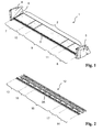
- Fig.1 shows a header mower table 1 according to the invention for front attachment to a harvester, which is intended in particular for harvesting oilseed rape and is therefore also referred to as rapeseed. It consists of a horizontal part 2 with a front cutting unit 3 and two vertical side parts 4 and 5. At the transition to the horizontal part 2 is on the side panels 4 and 5 each have a flexible sealing lip 6 is attached, which seals the local gap.
- the horizontal part 2 is composed of several modules, namely two side end modules 7 and 8, to which each directly connect the two vertical side parts 4 and 5, from a central module 9, which is located centrally between the two end modules 7 and 8 , as well as two expansion modules 10 and 11, which are each arranged between the central module 9 and the two end modules 7 and 8.
- the expansion modules 10 and 11 are optional components that do not necessarily have to be present. If no expansion modules 10 and 11 are provided, the two end modules 7 and 8 are connected directly by the center module 9. In this case, the intent mower table 1 according to the invention has its minimum possible width, which is determined by the sum of the widths of the two end modules 7 and 8 and the central module 9. The widths of these modules 7, 8 and 9 are fixed and can not be varied.
- the two expansion modules 10 and 11 To adapt the width of the entire horizontal part 2 to the working width of a harvester to which the intent mower table 1 is to be grown, serve the two expansion modules 10 and 11. Their width is variable, ie depending on the working width of Harvesting machine, two expansion modules 10 and 11 matching width of a plurality of such modules of different widths are appropriately selected and installed between the two end modules 7 and 8 and the center module 9.
- the two expansion modules 10 and 11 are completely equal to each other, ie it is to realize a certain width of the horizontal part 2 except the two end modules 7 and 8 and the center module 9 only a single additional type of module in duplicate for the two expansion modules 10 and 11th needed.
- the horizontal part 2 consists of a support frame 12, as in Fig. 2 is shown and a panel which covers the support frame 12 at least on its upper side.
- Fig. 2 is the support frame 12 of the horizontal part 2 without fairing and without the side panels 4 and 5 to see. It consists of two frame end modules 13 and 14, a frame center module 15 and two frame extension modules 16 and 17.
- the individual modules 13 to 17 of the support frame 12 overlap in width and each two adjacent modules are bolted together in the region of their overlap.
- a fixed part 3A of the horizontal cutter 3 is mounted on the support frame 12.
- Fig. 3 The seen in the direction of the attachment table 1 left chairendmodul 14 of the support frame 12 is in Fig. 3 shown separately.
- the overlapping region 14A is characterized in which theticianendmodul 14 is superimposed during assembly of the support frame 12 with a corresponding portion of the adjacent frame extension module 17 and connected thereto by screws.
- the necessary holes are in Fig. 3 indicated by a plurality of points in the overlapping area 14A.
- Fig. 3 an opposite overlapping area 14B, in which thearguesendmodul 14 superimposed upon assembly with the side part 5 with projecting from this support profiles and is connected to this by screws.
- the necessary holes are in Fig. 3 also indicated by a plurality of points in the overlapping area 14B.
- the frame center module 15 is in Fig. 4 shown separately. There are at both ends overlapping areas 15A and 15B are marked, in which the compassionendmodul 15 superimposed during assembly of the support frame 12 with corresponding portions of the adjacent frame extension modules 16 and 17 and with these by screws is connected. The necessary holes are in Fig. 4 indicated by a plurality of points in the overlapping areas 15A and 15B.
- a frame extension module 17 is shown in FIG Fig. 5 shown separately. There, overlapping areas 17A and 17B are marked at both ends, in which the frame extension module 17 is superimposed upon assembly of the support frame 12 with corresponding portions of the adjacent frame center module 15 and the frame end module 14 and connected thereto by screws.
- the necessary holes are in Fig. 5 indicated by a plurality of points in the overlapping areas 17A and 17B.
- the fixed part 3A of the horizontal cutting unit 3 is also distributed to the individual modules 13 to 17 of the support frame 12.
- the individual sections of the fixed part 3A of the horizontal cutting unit are not yet completely assembled, ie parts of it are still missing in the overlapping areas 14A, 15A, 15B, 17A and 17B.
- the fixed part 3A of the horizontal cutting unit 3 is of course without gaps, as in Fig. 2 you can see.
- To the horizontal cutting unit 3 still includes a reversing knife in the lateral direction, which is also modular and consists of several individual sections which are interconnected.
- This knife does not need to be divided into modules of the same width as the support frame 12 of the horizontal part 2, but the number of sections of the knife and their length may differ from the modular arrangement of the support frame 12.
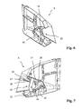
- the seen in the direction of the intent mower table 1 left side panel 5 is in Fig. 6 shown obliquely from the outside without the outer part of the panel.
- Two frame members 18 and 19 are obliquely to each other and together form a wedge-shaped cavity 20 open to the rear.
- the cavity 20 is intended for receiving a wedge-shaped front projection of the frame of a harvester during assembly of the attachment mower table 1 on the harvester.
- the frame parts 18 and 19 thus together constitute an engagement portion of the support frame of the side part 5, which in the mounted state of the attachment mower table. 1 is in contact with a projection of the frame of a harvester and has the shape of a hollow wedge stump.
- the right side panel 4 is constructed in mirror image to the left side panel 5.
- two frame members 21 and 22 form an engagement portion 21, 22 which forms a cavity 23 in the form of a truncated wedge for receiving a projection of the support frame of a harvester.
- a wedge-shaped adapter piece 24 is attached to the upper frame part 21 and a likewise wedge-shaped adapter piece 25 is attached to the lower frame part 22. Only the adapter pieces 24 and 25 are tailored to the shape of the projection of the frame of a particular harvester, while the side part 4 is universally usable for all harvesters and does not need to be customized.
- Fig. 7 is still a device for holding the side part 4 shown on a harvester, which consists of a fixed to the support frame of the side part 4 chain 26 with a hook 27 at the free end and a clamping device 28. If the header mower table 1 was placed on the frame of the harvester so that the machine-side frame projection projects into the receiving space 23 and rests there on the adapter pieces 24 and 25, then the hook 27 can be hung at a designated location in the support frame of the harvester and then the chain 26 are tensioned by means of the tensioning device 28. In the same way, the other side part 5 clamped to the harvester, so that the header mower table 1 can be attached to the harvester in total, without the need for tools.
- the identical holding device of the other side part 5 is in Fig. 6 , which shows only the support frame and the inner panel of the side member 5, not to see, but it is provided there. The latter also applies to adapter pieces on the frame parts 18 and 19.
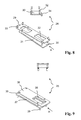
- FIGS. 8 and 9 Detail views of the adapter pieces 24 and 25 in Fig. 7 show the FIGS. 8 and 9 , As Fig. 8 can recognize, consists of the upper adapter piece 24 of four flat plates, namely an upper base plate 29 and a lower base plate 30 which are interconnected by two equal trapezoidal connecting plates 31 and 32 and preferably welded to these connecting plates 31 and 32.
- the connecting plates 31 and 32 are parallel to each other and perpendicular to the base plates 29 and 30, whose angles of inclination to each other define them by their trapezoidal shape.
- the adapter piece 24 has the shape of a truncated wedge.
- threaded bolts 33 are attached, by means of which the adapter piece 24 can be attached to the upper frame part 21 of the engagement portion 21, 22. This attachment of the adapter piece 24 is also in Fig. 7 recognizable.
- the top view in Fig. 8 shows the upper adapter piece 24 in a viewing direction which corresponds to the direction of the arrow A in the lower view.
- an extension 34 of the lower plate 30 can be seen, which extends obliquely beyond the connecting plate 32 and forms an angle of more than 90 ° with this. In Fig. 7 this extension 34 is also recognizable.
- the adapter piece 24 is located on the upper frame part 21 of the engagement portion 21, 22 and the base plate 30 on the underside of the adapter piece 24 so that when mounting the attachment mower table 1 to a harvester, the underside of the base plate 30 the Represents contact surface for the top of the right side tab of the frame of the harvester.
- the extension 34 thus extends in the assembled state of the side part 4 obliquely outwards and at the same time down.
- the wedge-shaped frame projection of the harvester in the direction of travel of the harvester automatically becomes centered between the adapter pieces 24 and 25.
- the intent mower table 1 due to gravity slides to the right if he is in contact with the adapter piece 24 is not in contact with the right frame projection of the harvester in a central position to the harvester, but should be offset to the left because then the contact is not on the flat bottom of the base plate 30, but on the oblique projection 34.
- the upper adapter piece on the left side part 5 which is not shown in the figures, has a corresponding projection which extends in mirror image to the extension 34, ie also obliquely outwards and at the same time downwards and thus ensures a displacement of the attachment mower table 1 to the left due to gravity, if this should not be positioned in the center of the harvester but offset to the right.
- the extension 34 on the upper adapter piece 24 in the right side part 4 and the corresponding extension on the upper adapter piece in the left side part 5 thus also effect an automatic centering of the attachment mower table 1 on the harvester in the lateral direction when the harvester with the projections its support frame in the receiving spaces 20 and 23 of the side parts 4 and 5 of the attachment mower table 1 in moves.
- Fig. 9 is still the lower adapter piece 25 shown in two views, of which the viewing direction of the upper view corresponds to the direction of the arrow A in the lower view.
- the construction of two base plates 35 and 36 and two connecting plates 37 and 38 is the same as in the upper adapter piece 24, the dimensions of the base plates 35 and 36 and the angle of inclination to each other but differ from the adapter piece 24.
- the angle of inclination here is much lower and the direction of the inclination is opposite, ie, the lower adapter piece 25 does not contribute in contrast to the upper adapter piece 24 in the mounted state to a reduction of the wedge angle of the receiving space 23, but instead to an enlargement.
- the adapter piece 25 is located on the lower frame part 22 of the engagement portion 21, 22 and the base plate 36 at the top of the adapter piece 25, so that when mounting the attachment mower table 1 on a harvester, the top of the base plate 36 the Representing contact surface for the bottom of the right side tab of the frame of the harvester.
- the lower frame part 22 of the engaging portion 21, 22 and the lower adapter piece 25 is provided with threaded bolts 39.
- the two adapter pieces of the other side part 5, not shown here, can be shaped mirror-inverted to the adapter pieces 24 and 25, but they do not have to. If the support frame of a harvester transverse to the direction of travel has an asymmetrical shape, the adapter pieces of the other side part 5 may have other shapes, so that a total of four different adapters for mounting the attachment mower table 1 to the harvester use, each of which is exactly a specific frame part 18th , 19, 21 or 22 of one of the side parts 4 or 5 is assigned.
- the inventive adaptation of the attachment of a header mower to different harvesters through the use of adapters and the inventive adaptation of the width of a header mower to the working widths of different harvesters by a modular structure of the horizontal portion are measures of independent advantageous effect in the sense of the aforementioned task of the present invention, however, they can also be combined with each other to maximize the beneficial effect.
- the combination of both measures results overall in a modular system for the realization of a header mower table, which mainly consists of standard components and contains only a few special components for adaptation to different harvesting machines.
- the attachment of the intent mower table according to the invention on a harvester on the side parts has been previously described in detail only with reference to one of the two side parts.
- the fastening on the other side is the same, wherein the adapter pieces are adapted on both sides in each case to the shapes of the projections of the support frame of the harvester.
Landscapes
- Life Sciences & Earth Sciences (AREA)
- Environmental Sciences (AREA)
- Harvester Elements (AREA)
Description
- Die Erfindung betrifft einen Vorsatzmähtisch nach dem Oberbegriff des Anspruchs 1.
- Es ist bekannt, zum Ernten bestimmter Nutzpflanzen wie Raps an eine Erntemaschine, insbesondere einen Mähdrescher, frontseitig einen Vorsatzmähtisch anzubauen, um den Aufnahmeraum für die geschnittenen Pflanzen in Fahrtrichtung der Erntemaschine zu vergrößern und dadurch die Ernteausbeute zu steigern. Üblicherweise erfolgt die Befestigung eines solchen Vorsatzmähtisches über vertikale Seitenteile, welche den Aufnahmeraum für die geschnittenen Pflanzen in seitlicher Richtung begrenzen, an Rahmenteilen der Erntemaschine.
- Zur Verwendung eines Vorsatzmähtisches gemäß
DE 196 32 895 A1 an einer Erntemaschine eines bestimmten Typs bedarf es einer individuellen Anpassung des Vorsatzmähtisches, insbesondere hinsichtlich der zur Montage an der Erntemaschine vorzusehenden Komponenten, sowie hinsichtlich der Breite, die der Arbeitsbreite der Erntemaschine entsprechen muss. Um einen Vorsatzmähtisch für eine große Anzahl verschiedener Erntemaschinen auf dem Markt anzubieten, sieht sich ein Hersteller deshalb mit der Notwendigkeit konfrontiert, für die verschiedenen Erntemaschinen eine entsprechend große Anzahl von individuellen Varianten eines Vorsatzmähtisches herzustellen, was den Aufwand und die Kosten der Fertigung sowie der Lagerhaltung erhöht. - Aus der
DE 10 2010 028 605 A1 ist die Befestigung eines Erntevorsatzes an einem Einzugsgehäuse einer Erntemaschine über einen Zwischenrahmen bekannt, der gegenüber dem Einzugsgehäuse über Rollen um eine sich in Vorwärtsrichtung der Erntemaschine erstreckende Achse beweglich gelagert ist und somit einen Pendelrahmen bildet. Er umgibt die gesamte Vorderseite des Einzugsgehäuses. - Aus der
DE 20 2007 011 411 U1 ist ein Adapter für die Anpassung eines Schneidwerkzeugs an ein Zerkleinerungswerkzeug einer Erntemaschine in Form eines Gehäusekastens bekannt, welcher einer Mehrzahl von Rahmen für die Stirnwand und/oder die Rückwand aufweist, die in ihren Abmessungen und Verbindungsvorrichtungen dem jeweils gewählten Schneid- bzw. Zerkleinerungswerkzeug angepasst und mit einem Gehäuserahmen des Adapters lösbar verbindbar sind. Der Adapter umgibt die gesamte Einzugsöffnung des Zerkleinerungswerkzeugs. - Solche rahmenförmigen Adapter haben einen relativ komplexen Aufbau, der entsprechende Kosten verursacht, sowie große Abmessungen und ein damit ein entsprechend hohes Gewicht, was die Handhabung bei der Montage und Demontage erschwert.
- In Anbetracht des Standes der Technik ist es die Aufgabe der Erfindung, einen einfachen Weg zur Herstellung eines an verschiedenen Erntemaschinen verwendbaren Vorsatzmähtisches aufzuzeigen.
- Diese Aufgabe wird erfindungsgemäß durch einen Vorsatzmähtisch mit den Merkmalen des Anspruchs 1 gelöst. Vorteilhafte Ausgestaltungen sind in den Unteransprüchen angegeben.
- Erfindungsgemäß weist bei einem Vorsatzmähtisch für eine Erntemaschine, mit einem Horizontalteil, an dessen Frontseite ein horizontales Schneidwerk angeordnet ist, und mit zwei vertikalen Seitenteilen, über welche der Vorsatzmähtisch mit der Erntemaschine verbindbar ist, ein Seitenteile jeweils einen seitlichen Tragrahmen mit einem Eingriffsabschnitt auf, der zum Eingriff mit einem Vorsprung eines Tragrahmens der Erntemaschine bestimmt ist. Einem seitlichen Tragrahmen ist jeweils mindestens ein Adapterstück zugeordnet, das an dem Eingriffsabschnitt befestigbar ist und dessen Form so an die Formen des Eingriffsabschnitts und des Vorsprungs angepasst ist, dass es im montierten Zustand des Vorsatzmähtisches an der Erntemaschine eine Auflagefläche für den Vorsprung bildet.
- Hierdurch ist es möglich, ein und dieselben Seitenteile zur Montage eines Vorsatzmähtisches an einer Vielzahl unterschiedlicher Erntemaschinen mit unterschiedlichen Formen des Vorsprungs am vorderen Endes des Tragrahmens, der zur Befestigung eines Vorsatzmähtisches zur Verfügung steht, zu verwenden. Die Anpassung zwischen den Eingriffsabschnitten der Seitenteile des Vorsatzmähtisches und den Vorsprüngen des Tragrahmens der Erntemaschine erfolgt allein durch die Adapterstücke, die Formunterschiede zwischen den Eingriffsabschnitten und den Vorsprüngen so ausgleichen, dass an den Seitenteilen des Vorsatzmähtisches passende Auflageflächen für die Vorsprünge zur Verfügung stehen und der Vorsatzmähtisch somit sicher und spielfrei an der Erntemaschine montiert werden kann. Es können dann universelle Seitenteile verwendet werden, die nicht an eine bestimmte Erntemaschine angepasst werden müssen, was die Herstellung des Vorsatzmähtisches insgesamt erheblich vereinfacht und eine Kostenersparnis ermöglicht.
- Besonders zweckmäßig ist es, wenn der Eingriffsabschnitt eines Seitenteils zwei Rahmenteile aufweist, die zusammen einen keilförmigen oder keilstumpfförmigen Aufnahmeraum mit einem Öffnungswinkel für den Vorsprung des Rahmens der Erntemaschine definieren, und wenn das Adapterstück die Form eines Keils oder Keilstumpfes hat und der Öffnungswinkel des Aufnahmeraumes durch die Befestigung des Adapterstücks an dem Eingriffsabschnitt veränderbar ist. Um einen keilförmigen Aufnahmeraum im Tragrahmen eines Seitenteils an ein ebenfalls keilförmiges Gegenstück mit anderem Keilwinkel am Tragrahmen der Erntemaschine anzupassen, wird nämlich lediglich ein keilförmiges Adapterstück benötigt, dessen Keilwinkel gerade den Winkelunterschied zwischen den beiden Keilformen ausgleicht.
- Obgleich in Grundsatz ein einziges Adapterstück in jedem Seitenteil des erfindungsgemäßen Vorsatzmähtisches ausreichen würde, um den seitlichen Tragrahmen des Seitenteils an den Tragrahmen einer Erntemaschine anzupassen, ist es von Vorteil, wenn einem seitlichen Tragrahmen jeweils zwei Adapterstücke zugeordnet sind, von denen jedes einem anderen der beiden Rahmenteile, welche den Aufnahmeraum definieren, zugeordnet ist. Hierdurch ergeben sich zusätzliche Freiheitgrade der Modifikation des Aufnahmeraumes, die eine optimale Positionierung des Vorsatzmähtisches an der Erntemaschine erlauben.
- Eine besonders einfache und daher vorteilhafte Ausbildung eines erfindungsgemäßen Adapterstücks besteht aus zwei Grundplatten und zwei trapezförmige Verbindungsplatten, welche die Grundplatten miteinander verbinden, wobei die Grundplatten in einem Winkel zueinander geneigt sind und die Verbindungsplatten durch ihre Trapezform den Neigungswinkel zwischen den Grundplatten definieren.
- Indem bei mindestens einem Adapterstück ein entlang einer Verbindungsplatte verlaufender Fortsatz einer Grundplatte seitlich über die ihm benachbarte Verbindungsplatte hinausragt und sich schräg zu dem übrigen Abschnitt der Grundplatte erstreckt, wobei er in einem Winkel von über 90° zu der ihm benachbarten Verbindungsplatte steht, wird es ermöglicht, dass der Vorsatzmähtisch beim Einführen des Vorsprungs des Rahmens der Erntemaschine in den Aufnahmeraum eines Seitenteils des Vorsatzmähtisches im Fall eines geringfügigen seitlichen Versatzes gegenüber der Erntemaschine automatisch seitlich in die richtige Position verschoben wird. Um eine automatische Zentrierung in seitlicher Richtung zu erreichen, ist es zweckmäßig, wenn an jedem der zwei Seitenteile jeweils ein Adapterstück mit einem seitlich schräg über eine der Verbindungsplatten hinausragenden Fortsatz an der Oberseite des ersten Eingriffsabschnitts vorgesehen ist, wobei sich der schräg hinausragende Abschnitt im fertig montierten Zustand an der unteren Grundplatte befindet und zur Außenseite des Seitenteils sowie nach unten weist.
- Zum Fixieren eines Eingriffsabschnitts eines seitlichen Tragrahmens eines Seitenteils des erfindungsgemäßen Vorsatzmähtisches im Kontakt mit dem zugehörigen Vorsprung des Tragrahmens der Erntemaschine eignet sich besonders eine Haltevorrichtung mit einem Zugmittel in Form einer Kette oder eines Seils, einem zum Eingriff mit dem Tragrahmen der Erntemaschine geeigneten Haken und einer Spannvorrichtung zum Spannen des Zugmittels. Ein Einsatz von Werkzeugen zum Befestigen des erfindungsgemäßen Vorsatzmähtisches an der Erntemaschine erübrigt sich in diesem Fall.
- Weiterhin kann bei einem erfindungsgemäßen Vorsatzmähtisch für eine Erntemaschine das Horizontalteil aus einer Vielzahl von miteinander verbundenen Modulen bestehen, wobei zumindest mehrere Grundmodule fester Breite vorgesehen sind und zusätzlich zu den Grundmodulen ein oder mehrere Erweiterungsmodule variabler Breite vorgesehen sein können, wodurch die Summe der Breiten der Grundmodule eine Mindestbreite des Horizontalteils definiert und die Breite des Horizontalteils allein durch die Anzahl und/oder Breite der Erweiterungsmodule einstellbar ist. Durch einen solchen modularen Aufbau des Horizontalteils ergibt sich ein Baukastensystem, das die Realisierung einer Vielzahl von Vorsatzmähtischen unterschiedlicher Breite mit geringem Aufwand erlaubt. Es werden nur wenige Erweiterungsmodule spezieller Breite benötigt, um die Gesamtbreite an diejenige einer beliebigen Erntemaschine anzupassen, während das Horizontalteil überwiegend aus Standardkomponenten fester Breite besteht. Die Herstellung eines Vorsatzmähtisches wird hierdurch deutlich vereinfacht.
- Zu den Grundmodulen gehören vorzugsweise zumindest zwei seitliche Endmodule, die jeweils mit den beiden vertikalen Seitenteilen verbunden sind sowie ein Mittelmodul, das symmetrisch in der Mitte des Horizontalteils angeordnet ist. Zwei gleichartige Erweiterungsmodule können jeweils zwischen dem Mittelmodul und jedem der zwei Endmodule vorgesehen sein. Hierdurch wird der Aufbau des Horizontalteils symmetrisch und die Grundmodule haben relativ kompakte Abmessungen, was den Transport der Module vereinfacht.
- Wenn der erfindungsgemäße Vorsatzmähtisch für das horizontale Schneidwerk und/oder zusätzliche vertikale, an den Seitenteilen montierbare Schneidwerke einen hydraulischen Antrieb aufweist, dann ist es vorteilhaft, wenn die Leitungen zur Verbindung von Komponenten des hydraulischen Antriebs in Form von Hochdruckschläuchen ausgeführt sind, da sich bei der Anpassung des Vorsatzmähtisches an unterschiedliche Erntemaschinen unterschiedliche Leitungslängen der Hydraulikleitungen ergeben, die am einfachsten durch Verwendung von Hochdruckschläuchen realisierbar sind, da Hochdruckschläuche nicht nur in unterschiedlichen Längen erhältlich sind, sondern ein Längenausgleich in gewissem Maße auch durch die Verlegung erfolgen kann.
- Die Anordnung flexibler Dichtlippen an den Übergängen vom Horizontalteil zu den Seitenteilen vereinfacht den Zusammenbau des erfindungsgemäßen Vorsatzmähtisches, indem sie eine zuverlässige Abdichtung an dieser Stelle auch bei einer relativ großen Spaltbreite gewährleistet.
- Nachfolgend werden Ausführungsbeispiele der Erfindung anhand der Zeichnungen beschrieben. In diesen zeigt
- Fig. 1
- einen erfindungsgemäßen Vorsatzmähtisch in einer perspektivischen Gesamtansicht,
- Fig. 2
- den Tragrahmen des Horizontalteils des Vorsatzmähtisches von
Fig. 1 , - Fig. 3
- ein in dem Tragrahmen nach
Fig. 2 enthaltenes seitliches Endmodul, - Fig. 4
- ein in dem Tragrahmen nach
Fig. 2 enthaltenes Mittelmodul, - Fig. 5
- ein in dem Tragrahmen nach
Fig. 2 optional montierbares Ergänzungsmodul, - Fig. 6
- den Tragrahmen und die Innenverkleidung eines Seitenteils des Vorsatzmähtisches von
Fig. 1 , - Fig. 7
- den Tragrahmen und die Innenverkleidung des anderen Seitenteils des Vorsatzmähtisches von
Fig. 1 mit zwei Adapterstücken und einer Haltevorrichtung, - Fig. 8
- zwei Ansichten eines der Adapterstücke von
Fig. 7 und - Fig. 9
- zwei Ansichten des anderen Adapterstücks von
Fig. 7 . -
Fig.1 zeigt einen erfindungsgemäßen Vorsatzmähtisch 1 zum frontseitigen Anbau an eine Erntemaschine, der insbesondere zum Ernten von Raps vorgesehen ist und daher auch als Rapstisch bezeichnet wird. Er besteht aus einem Horizontalteil 2 mit einem frontseitigen Schneidwerk 3 und aus zwei vertikalen Seitenteilen 4 und 5. Am Übergang zum Horizontalteil 2 ist an den Seitenteilen 4 und 5 jeweils eine flexible Dichtlippe 6 angebracht, die den dortigen Spalt abdichtet. Das Horizontalteil 2 setzt sich aus mehreren Modulen zusammen, nämlich aus zwei seitlichen Endmodulen 7 und 8, an die sich jeweils unmittelbar die beiden vertikalen Seitenteile 4 bzw. 5 anschließen, aus einem Mittelmodul 9, welches sich mittig zwischen den beiden Endmodulen 7 und 8 befindet, sowie aus zwei Erweiterungsmodulen 10 und 11, die jeweils zwischen dem Mittelmodul 9 und den beiden Endmodulen 7 und 8 angeordnet sind. - Während die beiden Endmodule 7 und 8 und das Mittelmodul 9 stets vorhanden sind, handelt es sich bei den Erweiterungsmodulen 10 und 11 um optionale Komponenten, die nicht unbedingt vorhanden sein müssen. Falls keine Erweiterungsmodule 10 und 11 vorgesehen sind, werden die beiden Endmodule 7 und 8 unmittelbar durch das Mittelmodul 9 verbunden. In diesem Fall hat der erfindungsgemäße Vorsatzmähtisch 1 seine minimal mögliche Breite, die durch die Summe der Breiten der beiden Endmodule 7 und 8 sowie des Mittelmoduls 9 vorgegeben ist. Die Breiten dieser Module 7, 8 und 9 sind fest und können nicht variiert werden.
- Zur Anpassung der Breite des gesamten Horizontalteils 2 an die Arbeitsbreite einer Erntemaschine, an welche der Vorsatzmähtisch 1 angebaut werden soll, dienen die beiden Erweiterungsmodule 10 und 11. Deren Breite ist variabel, d.h. je nach Arbeitsbreite der Erntemaschine werden zwei Erweiterungsmodule 10 und 11 passender Breite aus einer Vielzahl von solchen Modulen unterschiedlicher Breite passend ausgewählt und zwischen den beiden Endmodulen 7 und 8 und dem Mittelmodul 9 eingebaut. Die beiden Erweiterungsmodule 10 und 11 sind untereinander vollkommen gleich, d.h. es wird zur Realisierung einer bestimmten Breite des Horizontalteils 2 außer den beiden Endmodulen 7 und 8 und dem Mittelmodul 9 nur ein einziger zusätzlicher Typ eines Moduls in doppelter Ausführung für die beiden Erweiterungsmodule 10 und 11 benötigt.
- Das Horizontalteil 2 besteht aus einem Tragrahmen 12, wie er in
Fig. 2 dargestellt ist und einer Verkleidung, welche den Tragrahmen 12 zumindest auf seiner Oberseite abdeckt. InFig. 2 ist der Tragrahmen 12 des Horizontalteils 2 ohne Verkleidung und ohne die Seitenteile 4 und 5 zu sehen. Er besteht aus zwei Rahmenendmodulen 13 und 14, einem Rahmenmittelmodul 15 und zwei Rahmenerweiterungsmodulen 16 und 17. Die einzelnen Module 13 bis 17 des Tragrahmens 12 überlappen sich in der Breite und jeweils zwei einander benachbarte Module sind im Bereich ihrer Überlappung miteinander verschraubt. Ein feststehender Teil 3A des Horizontalschneidwerks 3 ist an dem Tragrahmen 12 montiert. - Das in Arbeitsrichtung des Vorsatztisches 1 gesehen linke Rahmenendmodul 14 des Tragrahmens 12 ist in
Fig. 3 separat gezeigt. Dort ist der Überlappungsbereich 14A gekennzeichnet, in dem das Rahmenendmodul 14 bei der Montage des Tragrahmens 12 mit einem entsprechenden Bereich des benachbarten Rahmenerweiterungsmoduls 17 übereinandergelegt und mit diesem durch Schrauben verbunden wird. Die hierzu nötigen Bohrungen sind inFig. 3 durch eine Vielzahl von Punkten in dem Überlappungsbereich 14A angedeutet. Ebenfalls gekennzeichnet ist inFig. 3 ein gegenüberliegender Überlappungsbereich 14B, in dem das Rahmenendmodul 14 beim Zusammenbau mit dem Seitenteil 5 mit von diesem abragenden Trägerprofilen übereinandergelegt und mit diesem durch Schrauben verbunden wird. Die hierzu nötigen Bohrungen sind inFig. 3 ebenfalls durch eine Vielzahl von Punkten in dem Überlappungsbereich 14B angedeutet. - Das Rahmenmittelmodul 15 ist in
Fig. 4 separat gezeigt. Dort sind an beiden Enden Überlappungsbereiche 15A und 15B gekennzeichnet, in denen das Rahmenendmodul 15 bei der Montage des Tragrahmens 12 mit entsprechenden Bereichen der benachbarten Rahmenerweiterungsmodule 16 und 17 übereinandergelegt und mit diesen durch Schrauben verbunden wird. Die hierzu nötigen Bohrungen sind inFig. 4 durch eine Vielzahl von Punkten in den Überlappungsbereichen 15A und 15B angedeutet. - Ein Rahmenerweiterungsmodul 17 ist in
Fig. 5 separat gezeigt. Dort sind an beiden Enden Überlappungsbereiche 17A und 17B gekennzeichnet, in denen das Rahmenerweiterungsmodul 17 bei der Montage des Tragrahmens 12 mit entsprechenden Bereichen des benachbarten Rahmenmittelmoduls 15 und des Rahmenendmoduls 14 übereinandergelegt und mit diesem durch Schrauben verbunden wird. Die hierzu nötigen Bohrungen sind inFig. 5 durch eine Vielzahl von Punkten in den Überlappungsbereiche 17A und 17B angedeutet. - Wie aus den
Figuren 2 bis 5 hervorgeht, verteilt sich der feststehende Teil 3A des Horizontalschneidwerks 3 ebenfalls auf die einzelnen Module 13 bis 17 des Tragrahmens 12. In denFiguren 3 bis 5 sind die einzelnen Abschnitte des feststehenden Teils 3A des Horizontalschneidwerks noch nicht fertig montiert, d.h. es fehlen dort noch Teile davon in den Überlappungsbereichen 14A, 15A, 15B, 17A und 17B. Im fertig montierten Zustand ist der feststehende Teil 3A des Horizontalschneidwerks 3 selbstverständlich ohne Lücken, wie es inFig. 2 zu sehen ist. Zu dem Horizontalschneidwerk 3 gehört noch ein in seitlicher Richtung reversierendes Messer, das ebenfalls modular aufgebaut ist und aus mehreren einzelnen Abschnitten besteht, die miteinander verbunden sind. Dieses in den Figuren nicht sichtbare Messer braucht nicht in ebenso viele Module entsprechender Breite aufgeteilt zu sein wie der Tragrahmen 12 des Horizontalteils 2, sondern die Anzahl der Abschnitte des Messers und deren Länge kann von der Moduleinteilung des Tragrahmens 12 abweichen. Das in Arbeitsrichtung des Vorsatzmähtisches 1 gesehen linke Seitenteil 5 ist inFig. 6 von schräg von außen ohne den äußeren Teil der Verkleidung gezeigt. Wie dort zu erkennen ist, weist das Seitenteil 5 im Inneren einen Tragrahmen auf, der aus einer Reihe von miteinander verbundenen Blechen besteht. Zwei Rahmenteile 18 und 19 stehen schräg zueinander und bilden zusammen einen nach hinten offenen keilförmigen Hohlraum 20. Der Hohlraum 20 ist zur Aufnahme eines ebenfalls keilförmig ausgebildeten vorderen Vorsprungs des Rahmens einer Erntemaschine bei der Montage des Vorsatzmähtisches 1 an der Erntemaschine bestimmt. Die Rahmenteile 18 und 19 stellen also zusammen einen Eingriffsabschnitt des Tragrahmens des Seitenteils 5 dar, der sich im montierten Zustand des Vorsatzmähtisches 1 im Kontakt mit einem Vorsprung des Rahmens einer Erntemaschine befindet und die Form eines Hohlkeilstumpfes hat. - Um einen flächigen Kontakt der einen Eingriffsabschnitt 18, 19 bildenden Rahmenteile 18 und 19 des Seitenteils 5 mit dem Vorsprung des Rahmens der Erntemaschine und damit einen sicheren Halt des Vorsatzmähtisches 1 an der Erntemaschine zu gewährleisten, ist es eigentlich nötig, dass der Keilwinkel des Eingriffsabschnitts 18, 19 am Seitenteil 5 und des in den Figuren nicht sichtbaren Vorsprungs des Rahmens der Erntemaschine übereinstimmen, wozu der Eingriffsabschnitt 18, 19 individuell für jede einzelne Erntemaschine, an welcher der Vorsatzmähtisch 1 angebaut werden soll, modifiziert werden müsste. Wie dies erfindungsgemäß vermieden wird, zeigt
Fig. 7 , bei der es sich um eine Ansicht des anderen, also des rechten Seitenteils 4 schräg von außen ohne den äußeren Teil der Verkleidung handelt. - Wie bei einer vergleichenden Betrachtung der
Figuren 6 und 7 ohne weiteres erkennbar ist, ist das rechte Seitenteil 4 spiegelbildlich zu dem linken Seitenteil 5 aufgebaut. Auch hier bilden zwei Rahmenteile 21 und 22 einen Eingriffsabschnitt 21, 22, der einen Hohlraum 23 in Form eines Keilstumpfes für die Aufnahme eines Vorsprungs des Tragrahmens einer Erntemaschine bildet. Um den Keilwinkel des Hohlraumes 23 an denjenigen des Vorsprungs des Tragrahmens der Erntemaschine anzupassen, ist an dem oberen Rahmenteil 21 ein keilförmiges Adapterstück 24 und an dem unteren Rahmenteil 22 ein ebenfalls keilförmiges Adapterstück 25 befestigt. Nur die Adapterstücke 24 und 25 sind auf die Form des Vorsprungs des Rahmens einer bestimmten Erntemaschine zugeschnitten, während das Seitenteil 4 universell für alle Erntemaschinen verwendbar ist und nicht individuell angepasst zu werden braucht. - In
Fig. 7 ist noch eine Vorrichtung zum Halten des Seitenteils 4 an einer Erntemaschine gezeigt, die aus einer an dem Tragrahmen des Seitenteils 4 befestigten Kette 26 mit einem Haken 27 am freien Ende und einer Spannvorrichtung 28 besteht. Wenn der Vorsatzmähtisch 1 auf den Rahmen der Erntemaschine so aufgesetzt wurde, dass der maschinenseitige Rahmenvorsprung in den Aufnahmeraum 23 hineinragt und dort auf den Adapterstücken 24 und 25 aufliegt, dann kann der Haken 27 an einer dafür vorgesehenen Stelle in den Tragrahmen der Erntemaschine eingehängt und anschließend die Kette 26 mittels der Spannvorrichtung 28 gespannt werden. Auf dieselbe Weise wird auch das andere Seitenteil 5 an die Erntemaschine gespannt, womit der Vorsatzmähtisch 1 insgesamt an der Erntemaschine befestigt werden kann, ohne dass dazu Werkzeuge benötigt werden. Die identische Haltevorrichtung des anderen Seitenteils 5 ist inFig. 6 , die nur den Tragrahmen und die innere Verkleidung des Seitenteils 5 zeigt, nicht zu sehen, aber sie ist dort vorgesehen. Letzeres gilt auch für Adapterstücke an den Rahmenteilen 18 und 19. - Detailansichten der Adapterstücke 24 und 25 in
Fig. 7 zeigen dieFiguren 8 und 9 . WieFig. 8 erkennen lässt, besteht das obere Adapterstück 24 aus vier ebenen Platten, nämlich einer oberen Grundplatte 29 und einer unteren Grundplatte 30, die durch zwei gleiche trapezförmige Verbindungsplatten 31 und 32 miteinander verbunden und vorzugsweise mit diesen Verbindungsplatten 31 und 32 verschweißt sind. Die Verbindungsplatten 31 und 32 stehen parallel zueinander und senkrecht zu den Grundplatten 29 und 30, deren Neigungswinkel zueinander sie durch ihre Trapezform definieren. Insgesamt hat das Adapterstück 24 die Form eines Keilstumpfes. In den vier Ecken der oberen Grundplatte 29 sind Gewindebolzen 33 angebracht, mittels derer das Adapterstück 24 an dem oberen Rahmenteil 21 des Eingriffsabschnitts 21, 22 befestigt werden kann. Diese Befestigung des Adapterstücks 24 ist auch inFig. 7 erkennbar. - Die obere Ansicht in
Fig. 8 zeigt das obere Adapterstück 24 in einer Ansichtsrichtung, welche der Richtung des Pfeiles A in der unteren Ansicht entspricht. Dort ist ein Fortsatz 34 der unteren Platte 30 erkennbar, der sich schräg über die Verbindungsplatte 32 hinaus erstreckt und mit dieser einen Winkel von über 90° bildet. InFig. 7 ist dieser Fortsatz 34 ebenfalls erkennbar. Im fertig montierten Zustand des Seitenteils 4 befindet sich das Adapterstück 24 an dem oberen Rahmenteil 21 des Eingriffsabschnitts 21, 22 und die Grundplatte 30 an der Unterseite des Adapterstücks 24, so dass bei der Montage des Vorsatzmähtisches 1 an einer Erntemaschine die Unterseite der Grundplatte 30 die Kontaktfläche für die Oberseite des Vorsprungs der rechten Seite des Rahmens der Erntemaschine darstellt. Der Fortsatz 34 erstreckt sich folglich im fertig montierten Zustand des Seitenteils 4 schräg nach außen und zugleich nach unten. - Wenn die Erntemaschine zur Montage des Vorsatzmähtisches 1 an den hierzu bereitliegenden Vorsatzmähtisch 1 heranfährt und der rechte Vorsprung des Tragrahmens der Erntemaschine in den keilstumpfförmigen Hohlraum 23 eintaucht, dann wird der keilförmige Rahmenvorsprung der Erntemaschine in Fahrtrichtung der Erntemaschine automatisch zwischen den Adapterstücken 24 und 25 zentriert. Für eine Zentrierung quer zur Fahrtrichtung sorgt der Fortsatz 34, indem der Vorsatzmähtisch 1 schwerkraftbedingt nach rechts gleitet, falls er sich beim Kontakt des rechten Rahmenvorsprungs der Erntemaschine mit dem Adapterstück 24 nicht in einer mittigen Position zu der Erntemaschine befindet, sondern nach links versetzt sein sollte, weil dann der Kontakt nicht an der ebenen Unterseite der Grundplatte 30, sondern an dem schrägen Fortsatz 34 erfolgt.
- Das in den Figuren nicht gezeigte obere Adapterstück an dem linken Seitenteil 5 weist einen entsprechenden Fortsatz auf, der sich spiegelbildlich zu dem Fortsatz 34, also ebenfalls schräg nach außen und zugleich nach unten erstreckt und somit schwerkraftbedingt für eine Verschiebung des Vorsatzmähtisches 1 nach links sorgt, falls dieser gegenüber der Erntemaschine nicht mittig, sondern nach rechts versetzt positioniert sein sollte. Insgesamt bewirken der Fortsatz 34 an dem oberen Adapterstück 24 in dem rechten Seitenteil 4 und der korrespondierende Fortsatz an dem oberen Adapterstück in dem linken Seitenteil 5 somit auch eine automatische Zentrierung des Vorsatzmähtisches 1 an der Erntemaschine in lateraler Richtung, wenn sich die Erntemaschine mit den Vorsprüngen ihres Tragrahmens in die Aufnahmeräume 20 und 23 der Seitenteile 4 und 5 des Vorsatzmähtisches 1 hinein bewegt.
- In
Fig. 9 ist noch das untere Adapterstück 25 in zwei Ansichten dargestellt, von denen die Ansichtsrichtung der oberen Ansicht der Richtung des Pfeiles A in der unteren Ansicht entspricht. Man erkennt, dass der Aufbau aus zwei Grundplatten 35 und 36 sowie zwei Verbindungsplatten 37 und 38 der gleiche ist wie bei dem oberen Adapterstück 24, die Abmessungen der Grundplatten 35 und 36 und deren Neigungswinkel zueinander jedoch gegenüber dem Adapterstück 24 abweichen. Der Neigungswinkel ist hier wesentlich geringer und die Richtung der Neigung ist entgegengesetzt, d.h. das untere Adapterstück 25 trägt im Gegensatz zum oberen Adapterstück 24 im montierten Zustand nicht zu einer Verringerung des Keilwinkels des Aufnahmeraumes 23 bei, sondern stattdessen zu einer Vergrößerung. - Im fertig montierten Zustand des Seitenteils 4 befindet sich das Adapterstück 25 an dem unteren Rahmenteil 22 des Eingriffsabschnitts 21, 22 und die Grundplatte 36 an der Oberseite des Adapterstücks 25, so dass bei der Montage des Vorsatzmähtisches 1 an einer Erntemaschine die Oberseite der Grundplatte 36 die Kontaktfläche für die Unterseite des Vorsprungs der rechten Seite des Rahmens der Erntemaschine darstellt. Zur Befestigung an dem unteren Rahmenteil 22 des Eingriffsabschnitts 21, 22 ist auch das untere Adapterstück 25 mit Gewindebolzen 39 ausgestattet.
- Die zwei hier nicht gezeigten Adapterstücke des anderen Seitenteils 5 können spiegelbildlich zu den Adapterstücken 24 und 25 geformt sein, müssen es aber nicht. Falls der Tragrahmen einer Erntemaschine quer zur Fahrtrichtung eine unsymmetrische Form hat, können die Adapterstücke des anderen Seitenteils 5 auch andere Formen haben, so dass insgesamt vier verschiedene Adapterstücke zur Montage des Vorsatzmähtisches 1 an der Erntemaschine Verwendung finden, von denen jedes genau einem bestimmten Rahmenteil 18, 19, 21 oder 22 eines der Seitenteile 4 oder 5 zugeordnet ist. Es ist auch möglich, dass ausnahmsweise zur Anpassung eines Eingriffsabschnitts 21, 22 eines Seitenteils 4 nur ein einziges Adapterstück 24 oder 25 entweder an dem oberen Rahmenteil 21 oder an dem unteren Rahmenteil 22 ausreicht, so dass für beide Seitenteile 4 und 5 insgesamt nur zwei Adapterstücke benötigt werden. Die Grundform eines Keils oder Keilstumpfes ist bei allen Adapterstücken gegeben, wobei der Keilwinkel aber bei Bedarf auch ausnahmsweise Null sein kann, d.h. die Keilstumpfform zu einer Quaderform entartet sein kann.
- Die erfindungsgemäße Anpassung der Befestigung eines Vorsatzmähtisches an unterschiedliche Erntemaschinen durch den Einsatz von Adapterstücken und die erfindungsgemäße Anpassung der Breite eines Vorsatzmähtisches an die Arbeitsbreiten unterschiedlicher Erntemaschinen durch einen modularen Aufbau des Horizontalteils sind Maßnahmen von eigenständiger vorteilhafter Wirkung im Sinne der eingangs genannten Aufgabenstellung der vorliegenden Erfindung, die jedoch auch miteinander kombiniert werden können, um die vorteilhafte Wirkung zu maximieren. Durch die Kombination beider Maßnahmen ergibt sich insgesamt ein Baukastensystem zur Realisierung eines Vorsatzmähtisches, der sich überwiegend aus Standardkomponenten zusammensetzt und nur einige wenige Spezialkomponenten zur Anpassung an unterschiedliche Erntemaschinen enthält.
- Die Befestigung des erfindungsgemäßen Vorsatzmähtisches an einer Erntemaschine über die Seitenteile wurde vorausgehend nur anhand eines der beiden Seitenteile im Detail beschrieben. Grundsätzlich erfolgt die Befestigung auf der anderen Seite genauso, wobei die Adapterstücke auf beiden Seiten jeweils an die Formen der Vorsprünge des Tragrahmens der Erntemaschine angepasst sind.
Claims (13)
- Vorsatzmähtisch (1) für eine Erntemaschine, mit einem Horizontalteil (2), an dessen Frontseite ein horizontales Schneidwerk (3) angeordnet ist, und mit zwei vertikalen Seitenteilen (4, 5), über welche der Vorsatzmähtisch (1) mit der Erntemaschine verbindbar ist, wobei ein Seitenteil (4)
jeweils einen seitlichen Tragrahmen mit einem Eingriffsabschnitt (21, 22) aufweist, der zum Eingriff mit einem Vorsprung eines Tragrahmens der Erntemaschine bestimmt ist, dadurch gekennzeichnet,
dass einem seitlichen Tragrahmen mindestens
ein Adapterstück (24; 25) zugeordnet ist, das an dem Eingriffsabschnitt (21, 22) befestigbar ist und dessen Form so an die Formen des Eingriffsabschnitts (21, 22) und des Vorsprungs angepasst ist, dass es im montierten Zustand des Vorsatzmähtisches (1) an der Erntemaschine eine Auflagefläche für den Vorsprung bildet. - Vorsatzmähtisch nach Anspruch 1, dadurch gekennzeichnet, dass der Eingriffsabschnitt (21, 22) eines Seitenteils (4) zwei Rahmenteile (21, 22) aufweist, die zusammen einen keilförmigen oder keilstumpfförmigen Aufnahmeraum (23) mit einem Öffnungswinkel für den Vorsprung des Rahmens der Erntemaschine definieren, dass das Adapterstück (24; 25) die Form eines Keils oder Keilstumpfes hat, und dass der Öffnungswinkel des Aufnahmeraumes (23) durch die Befestigung des Adapterstücks (24; 25) an dem Eingriffsabschnitt (21, 22) verändert wird.
- Vorsatzmähtisch nach Anspruch 2, dadurch gekennzeichnet, dass einem seitlichen Tragrahmen jeweils zwei Adapterstücke (24; 25) zugeordnet sind, von denen jedes einem anderen der beiden Rahmenteile (21, 22), welche den Aufnahmeraum (23) definieren, zugeordnet ist.
- Vorsatzmähtisch nach einem der Ansprüche 1 bis 3, dadurch gekennzeichnet, dass ein Adapterstück (24; 25) zwei Grundplatten (29, 30; 35, 36) und zwei trapezförmige Verbindungsplatten (31, 32; 37, 38), welche die Grundplatten (29, 30; 35, 36) miteinander verbinden, aufweist, wobei die Grundplatten (29, 30; 35, 36) in einem Winkel zueinander geneigt sind und die Verbindungsplatten (31, 32; 37, 38) durch ihre Trapezform den Neigungswinkel zwischen den Grundplatten (29, 30; 35, 36) definieren.
- Vorsatzmähtisch nach Anspruch 4, dadurch gekennzeichnet, dass bei mindestens einem Adapterstück (24) ein entlang einer Verbindungsplatte (32) verlaufender Fortsatz (34) einer Grundplatte (30) seitlich über die ihm benachbarte Verbindungsplatte (32) hinausragt und sich schräg zu dem übrigen Abschnitt der Grundplatte (30) erstreckt, wobei er in einem Winkel von über 90° zu der ihm benachbarten Verbindungsplatte (32) steht.
- Vorsatzmähtisch nach Anspruch 5, dadurch gekennzeichnet, dass an jedem der zwei Seitenteile (4, 5) jeweils ein Adapterstück mit einem seitlich schräg über eine der Verbindungsplatten hinausragenden Fortsatz an dem oberen Rahmenteil (18; 21) des Eingriffsabschnitts (18, 19; 21, 22) vorgesehen ist, wobei sich der schräg hinausragende Fortsatz im fertig montierten Zustand an der unteren Grundplatte befindet und zur Außenseite des jeweiligen Seitenteils (4; 5) sowie nach unten weist.
- Vorsatzmähtisch nach einem der Ansprüche 1 bis 6, dadurch gekennzeichnet, dass an dem seitlichen Tragrahmen eines Seitenteils (4) jeweils eine Haltevorrichtung (26, 27, 28) zum Fixieren des jeweiligen Eingriffsabschnitts (21, 22) im Kontakt mit dem zugehörigen Vorsprung des Tragrahmens der Erntemaschine vorgesehen ist, wobei die Haltevorrichtung (26, 27, 28) ein Zugmittel (26) in Form einer Kette oder eines Seils, einen zum Eingriff mit dem Tragrahmen der Erntemaschine geeigneten Haken (27) und eine Spannvorrichtung (28) zum Spannen des Zugmittels (26) aufweist.
- Vorsatzmähtisch nach einem der Ansprüche 1 bis 7, dadurch gekennzeichnet, dass das Horizontalteil (2) aus einer Vielzahl von miteinander verbundenen Modulen (7, 8, 9, 10, 11) besteht, wobei zumindest mehrere Grundmodule (7, 8, 9) fester Breite vorgesehen sind und zusätzlich zu den Grundmodulen (7, 8, 9) ein oder mehrere Erweiterungsmodule (10, 11) variabler Breite vorgesehen sein können, wodurch die Summe der Breiten der Grundmodule (7, 8, 9) eine Mindestbreite des Horizontalteils (2) definiert und die Breite des Horizontalteils (2) allein durch die Anzahl und/oder die Breite der Erweiterungsmodule (10, 11) einstellbar ist.
- Vorsatzmähtisch nach Anspruch 8, dadurch gekennzeichnet, dass zu den Grundmodulen (7, 8, 9) zwei seitliche Endmodule (7, 8) gehören, die jeweils mit einem der beiden vertikalen Seitenteile (4, 5) verbunden sind.
- Vorsatzmähtisch nach Anspruch 9, dadurch gekennzeichnet, dass zu den Grundmodulen (7, 8, 9) ein Mittelmodul (9) gehört, das symmetrisch in der Mitte des Horizontalteils (2) angeordnet ist.
- Vorsatzmähtisch nach Anspruch 10, dadurch gekennzeichnet, dass jeweils eines von zwei gleichartigen Erweiterungsmodulen (10, 11) zwischen dem Mittelmodul (9) und jedem der zwei seitlichen Endmodule (10, 11) montierbar ist.
- Vorsatzmähtisch nach einem der Ansprüche 1 bis 11, dadurch gekennzeichnet, dass er für das horizontale Schneidwerk (3) und/oder zusätzliche vertikale, an den Seitenteilen montierbare Schneidwerke einen hydraulischen Antrieb aufweist, und dass die Leitungen zur Verbindung von Komponenten des hydraulischen Antriebs in Form von Hochdruckschläuchen ausgeführt sind.
- Vorsatzmähtisch nach einem der Ansprüche 1 bis 12, dadurch gekennzeichnet, dass an den Übergängen von den Seitenteilen (4, 5) zu dem Horizontalteil (2) flexible Dichtlippen (6) angeordnet sind.
Applications Claiming Priority (1)
| Application Number | Priority Date | Filing Date | Title |
|---|---|---|---|
| DE201210111766 DE102012111766A1 (de) | 2012-12-04 | 2012-12-04 | Vorsatzmähtisch für eine Erntemaschine |
Publications (2)
| Publication Number | Publication Date |
|---|---|
| EP2740345A1 EP2740345A1 (de) | 2014-06-11 |
| EP2740345B1 true EP2740345B1 (de) | 2015-11-25 |
Family
ID=49683561
Family Applications (1)
| Application Number | Title | Priority Date | Filing Date |
|---|---|---|---|
| EP13194852.3A Not-in-force EP2740345B1 (de) | 2012-12-04 | 2013-11-28 | Vorsatzmähtisch für eine Erntemaschine |
Country Status (2)
| Country | Link |
|---|---|
| EP (1) | EP2740345B1 (de) |
| DE (1) | DE102012111766A1 (de) |
Family Cites Families (6)
| Publication number | Priority date | Publication date | Assignee | Title |
|---|---|---|---|---|
| DE9422102U1 (de) * | 1994-05-26 | 1998-03-12 | Claas KGaA, 33428 Harsewinkel | Vorsatzschneidwerk für einen Mähdrescher |
| DE4428857C1 (de) * | 1994-08-04 | 1996-02-22 | Claas Ohg | Aufnahmetisch für Erntemaschinen |
| DE19632895C2 (de) * | 1996-08-16 | 2002-07-04 | Claas Kgaa Mbh | Mähdrescher |
| DE202007011411U1 (de) * | 2007-08-16 | 2007-10-18 | Thomas Gruber Kg | Adapter für Erntemaschinen |
| DE102009030548B4 (de) * | 2009-06-25 | 2013-07-04 | Biso Schrattenecker Gmbh | Erntevorsatz für eine Erntemaschine |
| DE102010028605A1 (de) * | 2010-05-05 | 2011-11-10 | Deere & Company | Antriebsanordnung für einen Erntevorsatz einer Erntemaschine |
-
2012
- 2012-12-04 DE DE201210111766 patent/DE102012111766A1/de not_active Ceased
-
2013
- 2013-11-28 EP EP13194852.3A patent/EP2740345B1/de not_active Not-in-force
Also Published As
| Publication number | Publication date |
|---|---|
| EP2740345A1 (de) | 2014-06-11 |
| DE102012111766A1 (de) | 2014-06-05 |
Similar Documents
| Publication | Publication Date | Title |
|---|---|---|
| EP0992187B1 (de) | Maschine zum Mähen von Mais und dgl. stengelartigem Erntegut | |
| DE19504244A1 (de) | Selbstfahrender Mähdrescher mit zweigeteiltem Schneidtisch | |
| DE10121014A1 (de) | Mähvorrichtung | |
| EP2134519A2 (de) | Vorrichtung zum trennen eines stranges aus plastischem material mit einem eine kerbvorrichtung und eine schneidevorrichtung tragenden träger | |
| DE102005016350A1 (de) | Erntevorsatz für landwirtschaftliche Erntemaschinen | |
| DE1782897C3 (de) | Kreiselmähmaschine | |
| DE1782844A1 (de) | Maehdrescher | |
| DE102021115812A1 (de) | Schlitzwandfräse | |
| DE4117272C2 (de) | Gerätehaltevorrichtung zur Verbindung eines Arbeitsgerätes mit einem Fahrzeugchassis | |
| DE102011008723A1 (de) | Erntevorsatz für eine Erntemaschine | |
| DE3830908C2 (de) | Selbstfahrener Mähdrescher mit zweigeteiltem Schneidwerk | |
| DE1977620U (de) | Vorrichtung zum anschliessen, insbesondere einer maehwerksbaugruppe an eine landmaschine, beispielsweise einen maehdrescher. | |
| EP1983149B1 (de) | Mäkler | |
| DE602004003579T2 (de) | Flexible verbindungsglieder für eine maschine umfassende erntevorrichtung zum ernten von früchten, beeren und dergleichen | |
| DE102005006216B4 (de) | Selbstfahrende landwirtschaftliche Erntemaschine | |
| EP1092341A1 (de) | Vorrichtung zur Aufnahme und Halterung einer Schneidwerksbaugruppe am schwenkbaren Schrägförderer eines selbstfahrenden Mähdreschers | |
| DE102006060785A1 (de) | Befestigungsschiene zur Befestigung von Ladeeinrichtungen auf dem Ladedeck eines Flugzeugs | |
| DE4428857C1 (de) | Aufnahmetisch für Erntemaschinen | |
| EP3653042B1 (de) | Schwenkbare sägevorrichtung zum zuschneiden von pflanzen | |
| DE102012102084B4 (de) | Verlade- und Transportvorrichtung für landwirtschaftliche Schneidwerke | |
| EP2740345A1 (de) | Vorsatzmähtisch für eine Erntemaschine | |
| DE2058255A1 (de) | Mit Abweisern am Schneidwerktisch versehener Maehdrescher | |
| DE2345494A1 (de) | Sammelblech-anordnung bei einem kolbenpflueck-vorsatzgeraet | |
| EP1252810B1 (de) | Antriebssystem einer Mähvorrichtung | |
| DE202012104701U1 (de) | Vorsatzmähtisch für eine Erntemaschine |
Legal Events
| Date | Code | Title | Description |
|---|---|---|---|
| PUAI | Public reference made under article 153(3) epc to a published international application that has entered the european phase |
Free format text: ORIGINAL CODE: 0009012 |
|
| 17P | Request for examination filed |
Effective date: 20131128 |
|
| AK | Designated contracting states |
Kind code of ref document: A1 Designated state(s): AL AT BE BG CH CY CZ DE DK EE ES FI FR GB GR HR HU IE IS IT LI LT LU LV MC MK MT NL NO PL PT RO RS SE SI SK SM TR |
|
| AX | Request for extension of the european patent |
Extension state: BA ME |
|
| R17P | Request for examination filed (corrected) |
Effective date: 20141115 |
|
| RBV | Designated contracting states (corrected) |
Designated state(s): AL AT BE BG CH CY CZ DE DK EE ES FI FR GB GR HR HU IE IS IT LI LT LU LV MC MK MT NL NO PL PT RO RS SE SI SK SM TR |
|
| GRAP | Despatch of communication of intention to grant a patent |
Free format text: ORIGINAL CODE: EPIDOSNIGR1 |
|
| INTG | Intention to grant announced |
Effective date: 20150608 |
|
| GRAS | Grant fee paid |
Free format text: ORIGINAL CODE: EPIDOSNIGR3 |
|
| GRAA | (expected) grant |
Free format text: ORIGINAL CODE: 0009210 |
|
| AK | Designated contracting states |
Kind code of ref document: B1 Designated state(s): AL AT BE BG CH CY CZ DE DK EE ES FI FR GB GR HR HU IE IS IT LI LT LU LV MC MK MT NL NO PL PT RO RS SE SI SK SM TR |
|
| REG | Reference to a national code |
Ref country code: GB Ref legal event code: FG4D Free format text: NOT ENGLISH |
|
| REG | Reference to a national code |
Ref country code: CH Ref legal event code: EP |
|
| REG | Reference to a national code |
Ref country code: AT Ref legal event code: REF Ref document number: 762117 Country of ref document: AT Kind code of ref document: T Effective date: 20151215 |
|
| REG | Reference to a national code |
Ref country code: IE Ref legal event code: FG4D Free format text: LANGUAGE OF EP DOCUMENT: GERMAN |
|
| REG | Reference to a national code |
Ref country code: DE Ref legal event code: R096 Ref document number: 502013001540 Country of ref document: DE |
|
| REG | Reference to a national code |
Ref country code: LT Ref legal event code: MG4D |
|
| REG | Reference to a national code |
Ref country code: NL Ref legal event code: MP Effective date: 20160225 |
|
| PG25 | Lapsed in a contracting state [announced via postgrant information from national office to epo] |
Ref country code: HR Free format text: LAPSE BECAUSE OF FAILURE TO SUBMIT A TRANSLATION OF THE DESCRIPTION OR TO PAY THE FEE WITHIN THE PRESCRIBED TIME-LIMIT Effective date: 20151125 Ref country code: ES Free format text: LAPSE BECAUSE OF FAILURE TO SUBMIT A TRANSLATION OF THE DESCRIPTION OR TO PAY THE FEE WITHIN THE PRESCRIBED TIME-LIMIT Effective date: 20151125 Ref country code: NL Free format text: LAPSE BECAUSE OF FAILURE TO SUBMIT A TRANSLATION OF THE DESCRIPTION OR TO PAY THE FEE WITHIN THE PRESCRIBED TIME-LIMIT Effective date: 20151125 Ref country code: IS Free format text: LAPSE BECAUSE OF FAILURE TO SUBMIT A TRANSLATION OF THE DESCRIPTION OR TO PAY THE FEE WITHIN THE PRESCRIBED TIME-LIMIT Effective date: 20160325 Ref country code: NO Free format text: LAPSE BECAUSE OF FAILURE TO SUBMIT A TRANSLATION OF THE DESCRIPTION OR TO PAY THE FEE WITHIN THE PRESCRIBED TIME-LIMIT Effective date: 20160225 Ref country code: LT Free format text: LAPSE BECAUSE OF FAILURE TO SUBMIT A TRANSLATION OF THE DESCRIPTION OR TO PAY THE FEE WITHIN THE PRESCRIBED TIME-LIMIT Effective date: 20151125 |
|
| PG25 | Lapsed in a contracting state [announced via postgrant information from national office to epo] |
Ref country code: BE Free format text: LAPSE BECAUSE OF NON-PAYMENT OF DUE FEES Effective date: 20151130 Ref country code: PL Free format text: LAPSE BECAUSE OF FAILURE TO SUBMIT A TRANSLATION OF THE DESCRIPTION OR TO PAY THE FEE WITHIN THE PRESCRIBED TIME-LIMIT Effective date: 20151125 Ref country code: RS Free format text: LAPSE BECAUSE OF FAILURE TO SUBMIT A TRANSLATION OF THE DESCRIPTION OR TO PAY THE FEE WITHIN THE PRESCRIBED TIME-LIMIT Effective date: 20151125 Ref country code: PT Free format text: LAPSE BECAUSE OF FAILURE TO SUBMIT A TRANSLATION OF THE DESCRIPTION OR TO PAY THE FEE WITHIN THE PRESCRIBED TIME-LIMIT Effective date: 20160325 Ref country code: SE Free format text: LAPSE BECAUSE OF FAILURE TO SUBMIT A TRANSLATION OF THE DESCRIPTION OR TO PAY THE FEE WITHIN THE PRESCRIBED TIME-LIMIT Effective date: 20151125 Ref country code: LV Free format text: LAPSE BECAUSE OF FAILURE TO SUBMIT A TRANSLATION OF THE DESCRIPTION OR TO PAY THE FEE WITHIN THE PRESCRIBED TIME-LIMIT Effective date: 20151125 Ref country code: FI Free format text: LAPSE BECAUSE OF FAILURE TO SUBMIT A TRANSLATION OF THE DESCRIPTION OR TO PAY THE FEE WITHIN THE PRESCRIBED TIME-LIMIT Effective date: 20151125 Ref country code: GR Free format text: LAPSE BECAUSE OF FAILURE TO SUBMIT A TRANSLATION OF THE DESCRIPTION OR TO PAY THE FEE WITHIN THE PRESCRIBED TIME-LIMIT Effective date: 20160226 |
|
| PG25 | Lapsed in a contracting state [announced via postgrant information from national office to epo] |
Ref country code: IT Free format text: LAPSE BECAUSE OF FAILURE TO SUBMIT A TRANSLATION OF THE DESCRIPTION OR TO PAY THE FEE WITHIN THE PRESCRIBED TIME-LIMIT Effective date: 20151125 Ref country code: CZ Free format text: LAPSE BECAUSE OF FAILURE TO SUBMIT A TRANSLATION OF THE DESCRIPTION OR TO PAY THE FEE WITHIN THE PRESCRIBED TIME-LIMIT Effective date: 20151125 |
|
| REG | Reference to a national code |
Ref country code: IE Ref legal event code: MM4A |
|
| REG | Reference to a national code |
Ref country code: DE Ref legal event code: R097 Ref document number: 502013001540 Country of ref document: DE |
|
| PG25 | Lapsed in a contracting state [announced via postgrant information from national office to epo] |
Ref country code: SM Free format text: LAPSE BECAUSE OF FAILURE TO SUBMIT A TRANSLATION OF THE DESCRIPTION OR TO PAY THE FEE WITHIN THE PRESCRIBED TIME-LIMIT Effective date: 20151125 Ref country code: EE Free format text: LAPSE BECAUSE OF FAILURE TO SUBMIT A TRANSLATION OF THE DESCRIPTION OR TO PAY THE FEE WITHIN THE PRESCRIBED TIME-LIMIT Effective date: 20151125 Ref country code: SK Free format text: LAPSE BECAUSE OF FAILURE TO SUBMIT A TRANSLATION OF THE DESCRIPTION OR TO PAY THE FEE WITHIN THE PRESCRIBED TIME-LIMIT Effective date: 20151125 Ref country code: DK Free format text: LAPSE BECAUSE OF FAILURE TO SUBMIT A TRANSLATION OF THE DESCRIPTION OR TO PAY THE FEE WITHIN THE PRESCRIBED TIME-LIMIT Effective date: 20151125 Ref country code: RO Free format text: LAPSE BECAUSE OF FAILURE TO SUBMIT A TRANSLATION OF THE DESCRIPTION OR TO PAY THE FEE WITHIN THE PRESCRIBED TIME-LIMIT Effective date: 20151125 |
|
| PG25 | Lapsed in a contracting state [announced via postgrant information from national office to epo] |
Ref country code: MC Free format text: LAPSE BECAUSE OF FAILURE TO SUBMIT A TRANSLATION OF THE DESCRIPTION OR TO PAY THE FEE WITHIN THE PRESCRIBED TIME-LIMIT Effective date: 20151125 |
|
| PLBE | No opposition filed within time limit |
Free format text: ORIGINAL CODE: 0009261 |
|
| STAA | Information on the status of an ep patent application or granted ep patent |
Free format text: STATUS: NO OPPOSITION FILED WITHIN TIME LIMIT |
|
| PG25 | Lapsed in a contracting state [announced via postgrant information from national office to epo] |
Ref country code: IE Free format text: LAPSE BECAUSE OF NON-PAYMENT OF DUE FEES Effective date: 20151128 |
|
| 26N | No opposition filed |
Effective date: 20160826 |
|
| REG | Reference to a national code |
Ref country code: FR Ref legal event code: ST Effective date: 20161024 |
|
| PG25 | Lapsed in a contracting state [announced via postgrant information from national office to epo] |
Ref country code: SI Free format text: LAPSE BECAUSE OF FAILURE TO SUBMIT A TRANSLATION OF THE DESCRIPTION OR TO PAY THE FEE WITHIN THE PRESCRIBED TIME-LIMIT Effective date: 20151125 |
|
| PG25 | Lapsed in a contracting state [announced via postgrant information from national office to epo] |
Ref country code: FR Free format text: LAPSE BECAUSE OF NON-PAYMENT OF DUE FEES Effective date: 20160125 |
|
| PG25 | Lapsed in a contracting state [announced via postgrant information from national office to epo] |
Ref country code: HU Free format text: LAPSE BECAUSE OF FAILURE TO SUBMIT A TRANSLATION OF THE DESCRIPTION OR TO PAY THE FEE WITHIN THE PRESCRIBED TIME-LIMIT; INVALID AB INITIO Effective date: 20131128 Ref country code: BG Free format text: LAPSE BECAUSE OF FAILURE TO SUBMIT A TRANSLATION OF THE DESCRIPTION OR TO PAY THE FEE WITHIN THE PRESCRIBED TIME-LIMIT Effective date: 20151125 |
|
| PG25 | Lapsed in a contracting state [announced via postgrant information from national office to epo] |
Ref country code: CY Free format text: LAPSE BECAUSE OF FAILURE TO SUBMIT A TRANSLATION OF THE DESCRIPTION OR TO PAY THE FEE WITHIN THE PRESCRIBED TIME-LIMIT Effective date: 20151125 |
|
| REG | Reference to a national code |
Ref country code: CH Ref legal event code: PL |
|
| PG25 | Lapsed in a contracting state [announced via postgrant information from national office to epo] |
Ref country code: LI Free format text: LAPSE BECAUSE OF NON-PAYMENT OF DUE FEES Effective date: 20161130 Ref country code: CH Free format text: LAPSE BECAUSE OF NON-PAYMENT OF DUE FEES Effective date: 20161130 |
|
| PG25 | Lapsed in a contracting state [announced via postgrant information from national office to epo] |
Ref country code: MT Free format text: LAPSE BECAUSE OF FAILURE TO SUBMIT A TRANSLATION OF THE DESCRIPTION OR TO PAY THE FEE WITHIN THE PRESCRIBED TIME-LIMIT Effective date: 20151125 |
|
| PG25 | Lapsed in a contracting state [announced via postgrant information from national office to epo] |
Ref country code: LU Free format text: LAPSE BECAUSE OF NON-PAYMENT OF DUE FEES Effective date: 20151128 |
|
| PG25 | Lapsed in a contracting state [announced via postgrant information from national office to epo] |
Ref country code: MK Free format text: LAPSE BECAUSE OF FAILURE TO SUBMIT A TRANSLATION OF THE DESCRIPTION OR TO PAY THE FEE WITHIN THE PRESCRIBED TIME-LIMIT Effective date: 20151125 |
|
| GBPC | Gb: european patent ceased through non-payment of renewal fee |
Effective date: 20171128 |
|
| PG25 | Lapsed in a contracting state [announced via postgrant information from national office to epo] |
Ref country code: AL Free format text: LAPSE BECAUSE OF FAILURE TO SUBMIT A TRANSLATION OF THE DESCRIPTION OR TO PAY THE FEE WITHIN THE PRESCRIBED TIME-LIMIT Effective date: 20151125 Ref country code: TR Free format text: LAPSE BECAUSE OF FAILURE TO SUBMIT A TRANSLATION OF THE DESCRIPTION OR TO PAY THE FEE WITHIN THE PRESCRIBED TIME-LIMIT Effective date: 20151125 |
|
| PG25 | Lapsed in a contracting state [announced via postgrant information from national office to epo] |
Ref country code: GB Free format text: LAPSE BECAUSE OF NON-PAYMENT OF DUE FEES Effective date: 20171128 |
|
| PGFP | Annual fee paid to national office [announced via postgrant information from national office to epo] |
Ref country code: AT Payment date: 20181120 Year of fee payment: 6 |
|
| PGFP | Annual fee paid to national office [announced via postgrant information from national office to epo] |
Ref country code: DE Payment date: 20190110 Year of fee payment: 6 |
|
| REG | Reference to a national code |
Ref country code: DE Ref legal event code: R119 Ref document number: 502013001540 Country of ref document: DE |
|
| REG | Reference to a national code |
Ref country code: AT Ref legal event code: MM01 Ref document number: 762117 Country of ref document: AT Kind code of ref document: T Effective date: 20191128 |
|
| PG25 | Lapsed in a contracting state [announced via postgrant information from national office to epo] |
Ref country code: DE Free format text: LAPSE BECAUSE OF NON-PAYMENT OF DUE FEES Effective date: 20200603 |
|
| PG25 | Lapsed in a contracting state [announced via postgrant information from national office to epo] |
Ref country code: AT Free format text: LAPSE BECAUSE OF NON-PAYMENT OF DUE FEES Effective date: 20191128 |