EP2739948B1 - Ir thermometry probe cover - Google Patents
Ir thermometry probe cover Download PDFInfo
- Publication number
- EP2739948B1 EP2739948B1 EP12820293.4A EP12820293A EP2739948B1 EP 2739948 B1 EP2739948 B1 EP 2739948B1 EP 12820293 A EP12820293 A EP 12820293A EP 2739948 B1 EP2739948 B1 EP 2739948B1
- Authority
- EP
- European Patent Office
- Prior art keywords
- cover
- probe
- cove
- probe cover
- flange
- Prior art date
- Legal status (The legal status is an assumption and is not a legal conclusion. Google has not performed a legal analysis and makes no representation as to the accuracy of the status listed.)
- Active
Links
- 239000000523 sample Substances 0.000 title claims description 225
- 238000004861 thermometry Methods 0.000 title 1
- 230000007246 mechanism Effects 0.000 claims description 39
- 239000011324 bead Substances 0.000 claims description 20
- 238000000034 method Methods 0.000 claims description 16
- 230000004044 response Effects 0.000 claims description 10
- 238000004519 manufacturing process Methods 0.000 claims description 4
- 230000001681 protective effect Effects 0.000 description 17
- 238000003780 insertion Methods 0.000 description 7
- 230000037431 insertion Effects 0.000 description 7
- 238000003860 storage Methods 0.000 description 5
- 230000013011 mating Effects 0.000 description 3
- 238000000465 moulding Methods 0.000 description 3
- 239000000047 product Substances 0.000 description 3
- 238000005452 bending Methods 0.000 description 2
- 230000015572 biosynthetic process Effects 0.000 description 2
- 238000012864 cross contamination Methods 0.000 description 2
- 230000036541 health Effects 0.000 description 2
- 238000001746 injection moulding Methods 0.000 description 2
- 101150049278 US20 gene Proteins 0.000 description 1
- 230000001154 acute effect Effects 0.000 description 1
- 230000002950 deficient Effects 0.000 description 1
- 230000001419 dependent effect Effects 0.000 description 1
- 238000006073 displacement reaction Methods 0.000 description 1
- 230000002349 favourable effect Effects 0.000 description 1
- 239000012467 final product Substances 0.000 description 1
- 239000012530 fluid Substances 0.000 description 1
- 230000005484 gravity Effects 0.000 description 1
- 238000005259 measurement Methods 0.000 description 1
- 238000012986 modification Methods 0.000 description 1
- 230000004048 modification Effects 0.000 description 1
- 238000003825 pressing Methods 0.000 description 1
- 230000008569 process Effects 0.000 description 1
- 230000000717 retained effect Effects 0.000 description 1
- 238000000926 separation method Methods 0.000 description 1
- 238000005728 strengthening Methods 0.000 description 1
- 238000012360 testing method Methods 0.000 description 1
- 238000003856 thermoforming Methods 0.000 description 1
- 238000007666 vacuum forming Methods 0.000 description 1
Images


Classifications
-
- G—PHYSICS
- G01—MEASURING; TESTING
- G01K—MEASURING TEMPERATURE; MEASURING QUANTITY OF HEAT; THERMALLY-SENSITIVE ELEMENTS NOT OTHERWISE PROVIDED FOR
- G01K13/00—Thermometers specially adapted for specific purposes
- G01K13/20—Clinical contact thermometers for use with humans or animals
- G01K13/25—Protective devices therefor, e.g. sleeves preventing contamination
- G01K13/252—Protective devices therefor, e.g. sleeves preventing contamination for tympanic thermometers
-
- G—PHYSICS
- G01—MEASURING; TESTING
- G01J—MEASUREMENT OF INTENSITY, VELOCITY, SPECTRAL CONTENT, POLARISATION, PHASE OR PULSE CHARACTERISTICS OF INFRARED, VISIBLE OR ULTRAVIOLET LIGHT; COLORIMETRY; RADIATION PYROMETRY
- G01J5/00—Radiation pyrometry, e.g. infrared or optical thermometry
- G01J5/0003—Radiation pyrometry, e.g. infrared or optical thermometry for sensing the radiant heat transfer of samples, e.g. emittance meter
- G01J5/0011—Ear thermometers
-
- G—PHYSICS
- G01—MEASURING; TESTING
- G01J—MEASUREMENT OF INTENSITY, VELOCITY, SPECTRAL CONTENT, POLARISATION, PHASE OR PULSE CHARACTERISTICS OF INFRARED, VISIBLE OR ULTRAVIOLET LIGHT; COLORIMETRY; RADIATION PYROMETRY
- G01J5/00—Radiation pyrometry, e.g. infrared or optical thermometry
- G01J5/02—Constructional details
- G01J5/021—Probe covers for thermometers, e.g. tympanic thermometers; Containers for probe covers; Disposable probes
-
- Y—GENERAL TAGGING OF NEW TECHNOLOGICAL DEVELOPMENTS; GENERAL TAGGING OF CROSS-SECTIONAL TECHNOLOGIES SPANNING OVER SEVERAL SECTIONS OF THE IPC; TECHNICAL SUBJECTS COVERED BY FORMER USPC CROSS-REFERENCE ART COLLECTIONS [XRACs] AND DIGESTS
- Y10—TECHNICAL SUBJECTS COVERED BY FORMER USPC
- Y10T—TECHNICAL SUBJECTS COVERED BY FORMER US CLASSIFICATION
- Y10T29/00—Metal working
- Y10T29/49—Method of mechanical manufacture
Definitions
- the present disclosure relates generally to a protective cover for the probe of a medical instrument that is insertable into a body cavity.
- thermometer a thermometer
- IR infrared
- the probe In order to prevent cross-contamination between patients, or health care workers and patients, the probe is generally enclosed within a protective cover which can be disposed of in a sanitary manner after it has been used.
- the covers are manufactured of plastic using different types of molding techniques, many of which produce products that have surface imperfections or which cannot be held to tight tolerances.
- unstacking such covers and placing them upon the probe of an instrument can be extremely difficult. For example, since such covers are generally connected and/or otherwise loaded onto the medical instrument by pressing the probe onto/into the first cover in the stack, the remaining covers beneath the first probe cover tend to wedge together and/or otherwise bind in the stack with each successive loading operation.
- probe covers can be damaged and dropped during removal from the stack. Displacement of a misshaped cover from the instrument probe during an examination can also be unnerving to both the attending health care individuals and the patient. Lastly, defective covers can hang up on the instrument during removal thus requiring unwanted manual handling of a potentially contaminated product.
- US20 10260230 (A1 ) discloses a removable protective cover for an insertion probe of a medical instrument and an ejector mechanism.
- US6022140 (A ) refers to a disposable cover for an infrared thermometer.
- Another object of the present disclosure is to provide for easy removal of a protective probe cover from a supply stack of covers.
- a further object of the present disclosure is to more positively secure a protective probe cover to a medical instrument to insure that the cover does not become dislodged during a patient examination.
- a still further object of the present disclosure is to allow for the free release of a used probe cover from a medical instrument.
- Yet another object of the present disclosure is to minimize the amount of manual handling that is required when loading and unloading a protective probe cover from a medical instrument.
- Still another object of the present disclosure is to minimize the risk of damaging a protective probe cover as the cover is being loaded upon a medical instrument.
- a probe cover as defined by appended claim 1, the probe cover being for a medical instrument that contains a probe that is suitable for insertion into a body cavity or a method of manufacturing such a probe cover according to claim 9.
- Favourable modifications are defined in the dependent claims.
- the invention refers to a system, comprising a probe cover and an ejector mechanism.
- a cover contains a flexible tubular body that compliments the probe and/or tip geometry of the instrument and a radially disposed flange that surround the proximal end of the body.
- a series of snap on fasteners removably connect the cover to the instrument.
- a camming surface is located on the outer face of the flange which coacts with a cam follower that is movably mounted upon the instrument to flex the cover sufficiently to open the fastener and release the cover from the instrument.
- Alignment tabs are further provided on the flange that mate with openings in the instrument to properly register the cover with regard to the instrument.
- a probe cover for a medical instrument in another exemplary embodiment, includes a distal end, a proximal end opposite the distal end, and an annular flange extending around the proximal end.
- the probe cover also includes a camming surface defined by the flange and configured to mate with an ejector mechanism of the instrument.
- a section of the flange may be configured to flex in response to application of a force to the camming surface by the ejector mechanism, wherein such flexing releases the cover from the instrument.
- a method of removing a probe cover from a medical instrument includes slidably engaging a cam follower surface of the medical instrument with a camming surface of the cover, the camming surface extending at least partially around a proximal end of the cover.
- the method also includes flexing a section of the proximal end in response to the engagement between the cam follower surface and the camming surface, and disengaging a cove defined by an inner surface of the cover from a detent bead of the instrument in response to the flexing.
- a system for probe cover storage includes a first probe cover having a distal end, a proximal end, an annular flange extending around the proximal end, and a camming surface defined by the flange and configured to mate with an ejector mechanism of the instrument.
- a section of the flange may be configured to flex in response to application of a force to the camming surface by the ejector mechanism.
- the first probe cover also includes a shelf extending along at least a portion of an outer surface of the flange and substantially perpendicular to a longitudinal axis of the cover.
- the system also includes a second probe cover stacked on top of the first probe cover such that the distal end of the first probe cover is disposed substantially adjacent to a distal end of the second probe cover.
- the second probe cover includes a base disposed on the shelf of the first probe cover such that a gap is formed between the first probe cover and the second probe cover, the gap extending from the shelf to the distal end of the first probe cover.
- a method of storing probe covers for a medical instrument includes desirably positioning a first probe cover at a storage location, and disposing a second probe cover on top of the first probe cover such that a distal end of the first probe cover is located substantially within a distal end of the second probe cover and a proximal end of the first probe cover is located substantially directly beneath and adjacent to a proximal end of the second probe cover.
- the method also includes mating a base formed on an inner surface of the second probe cover with a shelf formed on an outer surface of the first probe cover, the base maintaining a gap extending between the first and second surface.
- a probe cover for a medical instrument includes a substantially conical body having a distal end, a proximal end, and a flange annularly surrounding the proximal end, the body defining a longitudinal axis and tapering away from the longitudinal axis from the distal end toward the proximal end.
- the probe cover also includes an IR transparent lens disposed at the distal end of the body, and a cove formed by an inner surface of the body, the cove extending annularly around the body and being configured to receive a plurality of detent beads of the instrument for releasably connecting the probe cover to the instrument.
- the probe cover further includes a camming surface defined by the flange and configured to receive an ejector finger of the instrument, and a weakened section formed proximate the cove.
- the weakened section is configured to bend in response to an upward force applied to the camming surface by the ejector finger, wherein bending of the weakened section removes the cove from the plurality of detent beads and releases the probe cover from the instrument.
- the cover further includes an annular shelf extending transverse to the longitudinal axis, the shelf being disposed substantially above the cove and defined by a portion of an outer surface of the cover opposite the cove.
- Such an exemplary probe cover also includes a base configured to rest upon a shelf of an additional probe cover stacked therebeneath, wherein a maximum vertical distance between the camming surface and the base is greater than or equal to approximately half of a maximum vertical distance between the cove and the base. Moreover, in such an exemplary embodiment, a horizontal distance between a vertically uppermost portion of the face and a radially outermost portion of the cove is less than approximately twice the maximum vertical distance between the cove and the base.
- the present disclosure relates to a protective probe cover, generally referenced 10, that will be described herein with regard to an infrared thermometer 11. It should be clear to one skilled in the art, however, that an embodiment of the present disclosure can be used in conjunction with various other medical instruments having an extended probe for insertion into a body cavity.
- disposable protective covers are placed over the probes to mitigate the danger of cross contamination occurring during and after an examination.
- the covers found in the prior art are typically made of plastic and are fabricated using various molding processes. Many of these molding methods, however, create imperfections in the final product and are unable to hold the product to close tolerances, thus resulting in unwanted and potentially dangerous problems arising particularly during a medical procedure.
- probe covers that are fabricated by the injection molding process can be held to tight tolerances while still having a desired amount of flexibility that help overcome many fabrication problems.
- the exemplary probe covers described herein may comprise plastic covers that have been formed by one or more of vacuum forming, thermoforming, and injection molding.
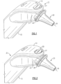
- Figs. 1-3 illustrate the top section of a hand held IR thermometer 11.
- the instrument includes a lower body section 12 and an upper head section 13 that contains an insertion probe that protrudes outwardly some distance from the head of the instrument.
- the proximal end section 15 of the probe is cylindrical in form and is secured by any suitable means to the head.
- the distal end 16 of the probe projects outwardly from the head and is conical shaped so as to taper downwardly from the cylindrical body of the probe towards the distal end tip 17.
- An IR sensor 18 is mounted in the tip of the probe. Although not shown, the sensor 18 is connected by electrical leads to a processor that is located within the body of the instrument which provides an accurate temperature read out to the user.
- the probe cover 10 is shown in Figs. 1 and 3 mounted upon the extended end of the probe in a locked position wherein the cover is securely fastened to the probe.
- the inner wall surface 53 of the cover complements the conical wall surface of probe.
- the cover 10 may be releasably secured to the probe by a series of snap-on fasteners 50.
- an ejector mechanism, generally referenced 25, is slidably mounted inside the instrument head upon the cylindrical section of the probe.
- the ejector mechanism is equipped with a circular ring 24 that surrounds the cylindrical section of the probe to provide a close running fit therebetween so that the ejector mechanism can be moved, for example, axially along the centerline 29 of the probe between a first cover locking position and a second cover releasing position.
- the ejector mechanism, or at least a component thereof may be moved along an arcuate path to facilitate release of the cover 10.
- the ring of the ejector mechanism contains a raised finger-engageable control button 26 that passes upwardly through an opening 27 contained in the head of the instrument.
- the control button is situated at the back of the opening as shown in Fig. 1 , the ejector mechanism is in the first probe locking position.
- Manual movement of the control button to the front of the opening as illustrated in Fig. 2 places the ejector mechanism a second probe releasing position.
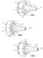
- FIG. 4 shows the probe without a cover.
- Two opposed arcuate shaped slots 33-33 are located in the probe mount 30 that are centered upon the longitudinal axis 29 of the probe.
- a pair of arcuate shaped fingers 35-35 that are integrally joined to the ejector ring 24 and are slidably contained within the slots 33-33. The fingers are arranged to be extended and retracted along an upward and/or arcuate path as the ejector moves between the first and second positions.
- each bead section is the male part of a two-part snap on fitting for releasably securing the probe cover 10 to the instrument.
- Preferably three equally spaced fittings are employed to secure the cover to the instruments, however, more or less fittings may be employed depending upon the particular application.
- Fig. 5 illustrates a protective cover 10 mounted in a locked position upon the probe.
- the flange 40 of the cover has engaged the fingers 35-35 of the ejector mechanism and has moved the ejector back to the cover locking position due to the rearward movement of the cover over the probe.
- Full rearward movement is attained when the snap-on fasteners engage the bead segments on the probe.
- Fig. 6 illustrates a probe cover located upon the probe with the ejector mechanism in the cover releasing position.
- the control button 25 ( Fig. 3 ) has been moved forward causing the ejector mechanism to unlock the fasteners thus releasing the cover.
- the continued movement of the ejector toward the distal end of the probe frees the cover from the probe.
- Figs. 7A , 7B , and 8 illustrate a first example of the apparatus for securing and releasing a probe cover from the instrument that does not fall into the scope of the claims to the extent that it does not relate to a probe cover or a method of manufacturing a probe cover.
- Fig 7A shows the above described ejector mechanism 25 moved back into the first cover locking position and a snap-on fasteners generally reference 50 in a cover securing condition. At this time the cover is snuggly contained upon the probe.
- the cover contains an IR transparent lens or window 19 mounted in the distal tip thereof which is now located in close proximity with the IR sensor 18 (see Fig. 3 ).
- Each snap-on fastener 50 includes two mating parts or sections. These include the previously noted bead segment 38 located upon the probe surface that mates with an arcuate and/or otherwise operatively shaped cove 42 that is contained in and/or formed by the inner wall surface 53 of the cover and/or the flange 40.
- the cove preferably extends circularly about the axis of the cover and services each of the detent beads.
- the cover wall section that encircles the cove provides a weakened section in the cover about which the cover can flex when an upward force is applied to the flange, such as at an outer face 56 of the flange.
- a weakened section may be disposed proximal to or distal to the cove 42.
- a circular camming surface 58 is contained in the outer face of the flange that runs along the rim of the flange.
- the camming surface may be defined by any portion of the flange convenient for receiving a component of the ejector mechanism 25.
- the camming surface may be angularly offset with regard to the axis of the cover.
- the distal end of the two fingers 35 of the ejector mechanism is provided with a arcuate surface 60 that is arranged to ride in contact with camming surface 58 as the ejector mechanism moves between the first and second positions. Surface 60 thus serves as a cam follower in system.
- surface 60 is shown arcuate in form, it can, in practice, be a flat surface that rides in sliding contact with camming surface 58 without departing from the teachings of the present invention.
- Fig. 7B shows the probe cover 10 in a locked position with the snap fitting closed thereby securing the cover to the probe.
- the ejector mechanism is in the cover locking position.
- Moving the ejector button forward moves the cam follower against the camming surface of flange causing the lower portion of the cover to flex about the weakened wall section which surrounds the cove 42.
- Sufficient flexure is provided to free the detent beads 38 from the cove 42.
- releasing the cover from the probe As shown in Fig. 8 , further forward movement of the ejector moves the cover well clear of the probe surface so that it can fall easily from probe under the influences of gravity.
- a series of semi circular tabs 65 are circumferentially spaced upon the outer face of the flange and arranged to mate with openings 66 in the raised shoulder 30 of the probe so that the snap-on fittings will mate properly at the time of closure.
- Figs. 11-15 illustrate exemplary embodiments of the probe cover 10.
- an exemplary probe cover 10 may define a distal end 82, a proximal end 84 opposite the distal end 82, and an annular flange 40 extending around the proximal end 84.
- the probe cover 10 may also define a longitudinal axis 92.
- the proximal end 84 and/or the flange 40 may define one or more components of the probe cover 10.
- the flange 40 may define the camming surface 58.
- the camming surface 58 may be formed at any desirable angle relative to the longitudinal axis 92 to facilitate engagement with one or more components of the ejector mechanism 25 discussed above.
- the camming surface 58 may be disposed at an acute included angle relative to the longitudinal axis 92 to facilitate a camming and/or otherwise slidable relationship between the camming surface 58 and, for example, a finger 35 of the ejector mechanism 25.
- the camming surface 58 may taper substantially upwardly and substantially inwardly from the proximal end 84 of the cover 10 toward the longitudinal axis 92 and/or the distal end 82.
- the camming surface 58 may define a peak 74 disposed at a highest vertical elevation along the camming surface 58 and relative to the longitudinal axis 92.
- the peak 74 may be formed by a substantially rounded portion of the camming surface 58 and/or of the inner surface 53 of the probe cover 10.
- the peak 74 may be defined as an angled portion of the camming surface 58 and/or of the inner surface 53.
- one or more portions of the flange 40 also define the weakened section 88.
- the weakened section 88 is formed by a portion of the cove 42.
- the weakened section 88 is disposed adjacent to the portion of the flange 40 forming the camming surface 58.
- the weakened section 88 is configured to bend, and/or otherwise flex in response to application of a force to the camming surface 58, and the range of flexing may depend upon, for example, the shape, size, and/or other configurations of the section 88.
- the flange 40 may define a base 72 of the probe cover.
- the base 72 may be substantially annular and, in an additional exemplary embodiment, the flange 40 may define a channel, break, and/or space (not shown) between two or more adjacent bases 72.
- Such a channel, break, and/or space may assist in reducing and/or eliminating, for example, the formation of a negative pressure between two adjacent stacked probe covers 10 during storage, and may thereby assist in removing such probe covers 10 from the stack for usage.
- the base 72 may comprise a substantially horizontal platform and/or other like surface configured to support the probe cover 10 while stacked, while in storage, and/or while removably connected to a medical instrument during use. As shown in, for example, Fig. 15 , the base 72 may extend substantially perpendicular to the longitudinal axis 92 and may be configured to rest upon a shelf 76 of an additional probe cover 10 stacked there beneath. In this way, the base 72 may be analogous to the tabs 65 shown in, for example, Fig. 10 .
- Such an exemplary shelf 76 may be defined by the flange 40, and in an exemplary embodiment, the shelf 76 may extend along at least a portion of an outer surface 78 of the probe cover 10 and/or flange 40. It is understood that the outer surface 78 of the probe cover 10 may form the outer surface of the flange 40, and the inner surface 53 of the probe cover 10 may form the inner surface of the flange 40. As shown in Fig. 11 , in an exemplary embodiment, the shelf 76 may extend substantially perpendicular to the longitudinal axis 92 of the cover 10. In additional exemplary embodiments, the shelf 76 may extend at any desirable angle relative to the longitudinal axis 92 to facilitate support of an additional probe cover 10 stacked thereon and/or to assist in releasably connecting the probe cover 10 to a medical instrument.
- the cove 42 is defined by the inner surface 53 of the probe cover 10, and at least a portion of the cove 42 may be formed by the flange 40.
- the cove 42 is shaped, sized, positioned, and/or otherwise configured to releasably mate with one or more detent beads 38 ( Fig. 14 ) to facilitate a removable connection between the medical instrument and the probe cover 10.
- the cove 42 may be formed by the same portion of the flange 40 forming the shelf 76.
- the cove 42 may be disposed substantially beneath the shelf 76 such that the cove 42 is at least partially defined by the same portion of the flange 40 that forms the shelf 76.
- a remainder of the cove 42 may be formed by one or more substantially vertical and/or otherwise angled, bent, and/or curved portions of the flange 40 and/or the inner surface 53.
- an exemplary probe cover 10 may define a maximum vertical distance Z between the camming surface 58 and the base 72. As shown in Fig. 11 , the maximum vertical distance Z may be measured from the base 72 to the peak 74, in a direction parallel to the longitudinal axis 92. The probe cover 10 may also define a maximum vertical distance X between the cove 42 and the base 72.
- the maximum vertical distance X may be measured from, for example, an uppermost portion of the cove 42 such as, for example, from substantially flat ceiling 43 of the cove 42 illustrated in Fig. 11 .
- the maximum vertical distance X may be measured from the base 72 to a distal-most portion 73 of the cove 42.
- the maximum vertical distance Z between the camming surface 58 and the base 72 may be greater than or equal to approximately half of the maximum vertical distance X between the cove 42 and the base 72. In additional exemplary embodiments, the maximum vertical distance Z may be greater than or equal to approximately 3/5 of the maximum vertical distance X. In still further exemplary embodiments, other desirable relationships between the maximum vertical distances, Z, X may be maintained in order to facilitate, for example, flexing of the weakened section 88 and/or release of the probe cover 10 from the medical instrument. In the exemplary embodiments of the present disclosure, the distance X may be between approximately 2.2 mm and approximately 2.3 mm. For example, the distance X may be equal to approximately 2.28 mm. In addition, the distance Z may be between approximately 1.7 mm and approximately 1.8 mm. For example, the distance Z may be equal to approximately 1.78 mm.
- any desirable horizontal distance Y between the peak 74 of the camming surface 58 and a radially outer-most portion of the cove 42 may be maintained to facilitate flexing of the weakened section 88.
- the horizontal distance Y may be measured from the radially outer most portion of the cove 42 and, in exemplary embodiments in which the cove 42 is substantially rounded ( Fig.
- the distance Y may be measured from a horizontal peak 75 of the cove 42.
- the horizontal distance Y may be less than approximately twice the maximum vertical distance X between the cove 42 and the base 72.
- the distance X may have any of the values discussed above and the distance Y may be between approximately 2.2 mm and approximately 2.3 mm.
- the distance Y may be equal to approximately 2.275 mm.
- the probe cover 10 may include one or more ribs 80.
- Such ribs 80 may be disposed on, for example, a radially outer-most portion of the flange 40.
- such ribs 80 may be disposed on one or more inner-portions of the flange 40.
- Such ribs 80 may assist in strengthening portions of the flange 40 and/or providing a desired level of structural rigidity thereto. Such added strength and/or structural rigidity may improve the functionality of, for example, the camming surface 58, the weakened section 88, and/or the cove 42.
- such added structural rigidity may assist the camming surface 58 in mating with the fingers 35 of the ejector mechanism 25 in order to desirably release the cover 10 from the medical instrument.
- such structural rigidity may assist the cove 42 in removably connecting with the detent bead 38.
- such ribs 80 may also assist in desirably spacing and/or aligning 2 or more probe covers 10 in a stacked configuration.
- such ribs 80 may assist in spacing each of the probe covers 10 relative to each other to further facilitate removal of each individual covers 10 from the stack.
- Such ribs 80 may have any shape, size, orientation, and/or other configuration in order to accentuate some of the advantages described above.
- FIG. 12 illustrates a plurality of ribs 80 disposed along an entire circumference of the probe cover 10, in additional exemplary embodiments, it is envisioned that one or more ribs 80 may be desirably disposed along only a portion of and/or portions of such circumferences.
- Figs. 17 and 18 illustrate additional exemplary embodiments of the probe cover 10 in which a substantially vertical extension 91 has been added to and/or defined by the camming surface 58.
- the embodiment of Fig. 17 does not include ribs 80, and is substantially structurally similar to the embodiment shown in Fig. 11
- the embodiment of Fig. 18 does include ribs 80 and is substantially structurally similar to the embodiment shown in Fig. 12 .
- such ribs 80 may increase the structural rigidity of, for example, the flange 40.
- the ejector mechanism 25 may be utilized to remove the probe cover 10 from a medical instrument such as, for example, an IR thermometer or other like device.
- the ejector mechanism 25 may be a component of such an instrument, and in an exemplary embodiment, the probe cover 10 may be removed from the instrument by slidably engaging the cam follower surface 60 of the finger 35 with the camming surface 58 of the cover 10.
- the finger 35 may be manually actuated by the user of the instrument, and as shown in Fig. 14 , one or more components of the ejector mechanism 25, such as the finger 35, may travel in a substantially arcuate path as it mates with the camming surface 58.
- Such an arcuate path is illustrated by arrow 90.
- the surface 60 may ride distally along substantially the entire camming surface 58 in removing the cover 10 from the instrument, and as the finger 35 is actuated in the direction of arrow 90, the flange 40 and/or other portions of the cover 10 may flex and/or otherwise bend about the weakened section of the flange 40. In an exemplary embodiment, such flexing may increase as the finger 35 is moved distally and/or in the direction of arrow 90. Flexing the cover 10 about the weakened section 88 in response to engagement between the surface 60 and the camming surface 58 may disengaged the cove 42 from the detent bead 38 of the instrument.
- the camming surface 58 may be moved in a direction toward the longitudinal axis 92 ( Figs. 11-13 ), and that as the cam follower surface 60 slidably engages the camming surface 58, the surface 60 may also move in a direction toward the longitudinal axis 92.
- the finger 35 in removing the cover 10 from the instrument, the finger 35 may be actuated distally along a path substantially away from the longitudinal axis 92.
- Such an exemplary path may be linear or arcuate, and in such exemplary embodiments as the cover 10 is flexed at the weakened portion, at least a portion of the camming surface 58 may be moved in a direction away from the longitudinal axis 92.
- the cam follower surface 60 slidably engages the camming surface 58 in such embodiments, the surface 60 may also move in a direction away from the longitudinal axis 92.
- a portion of the cove 42 may lift off of the detent bead 38.
- the actual point at which the cove 42 may disengaged from the detent bead 38 may vary depending on the shape, size, and/or other configurations of the various covers 42 and detent beads 38 described herein. It is understood that, however, moving at least a proximal portion of the cove 42 beyond a peak 39 of the detent bead 38 may disengaged the cove 42 therefrom. In exemplary embodiment, such a peak 39 may be defined by a radially outward-most point and/or section of the detent bead 38. For example, movement of the proximal portion of the cove 42 to the peak 39 and/or to a location distal to the peak 39 may disengaged the cove 42 from the detent bead 38.
- bending at least a portion of the flange 40 at the weakened section 88 may assist in separating at least a portion of the proximal end 84 of the probe cover 10 from the probe. In an exemplary embodiment, such separation may form and/or increase the size of a gap 94 between the inner surface 53 of the probe cover 10 and the distal end 16 of the probe.
- Fig. 16 illustrates an additional exemplary embodiment of the ejector mechanism 25 and probe cover shown in Fig. 14 .
- Fig. 15 illustrates a system for protecting an insertion probe of a medical device according to an exemplary embodiment of the present disclosure.
- a system may include one or more probe covers 10, 10a desirably stacked on top of each other. Such stacking may be convenient for storage and/or transportation of the probe covers 10, 10a.
- any of the probe covers 10 described herein may be stored and/or otherwise stacked as shown in Fig. 15 , and one or more components of the probe covers 10 described herein may assist in preventing deformation and/or damage to the respective probe covers 10 while stacked.
- one or more of the components described herein may assist in preventing adjacent probe covers 10, 10a from binding and/or otherwise sticking together when stacked. It is understood that such sticking may be caused by, for example, the formation of a negative pressure environment between surfaces of adjacent probe covers 10, 10a. Such sticking and/or wedging may also be caused by, for example, repeatedly applying axial/longitudinal force on the stack of adjacent probe covers 10 during attachment to the probe.
- one or more of the ribs 80, base 72, shelf 76, and/or other components of each respective probe cover 10 may assist in preventing stacked probe covers from sticking together.
- a second probe cover 10a may be disposed on top of a first probe cover 10 such that a distal end (not shown) of the first probe cover 10 is located substantially within a distal end (not shown) of the second probe cover 10a.
- the proximal end 84 of the first probe cover 10 may be located substantially directly beneath and/or adjacent to the proximal end 84 of the second probe cover 10a.
- one or more ribs 80 of the first probe cover 10 may mate with and/or otherwise engage one or more corresponding ribs 80 of the second probe cover 10a in such a stacked configuration. It is understood that engagement of such ribs 80 may assist in preventing two or more adjacent surfaces of the respective probe covers 10, 10a from sticking together while stacked.
- the probe covers 10, 10a may be stacked such that the base 72 of the second probe cover 10a is disposed upon and/or otherwise mated with the shelf 76 of the first probe cover 10.
- the shelf 76 may act as a hard stop preventing the second probe cover 10a from moving further in the direction of arrow 91.
- the base 72 of the second probe cover 10a may be disposed at any location laterally along the shelf 76, it may be desirable to substantially align the longitudinal axis 92 of the second probe cover 10a with the longitudinal axis 92 of the first probe cover 10 so as to maximize the surface area of the base 72 engaged with the shelf 76.
- the base 72 and/or the shelf 76 of each probe cover 10, 10a may be sized to account for an acceptable degree of misalignment therebetween while stacked.
- the shelf 76 may extend substantially annularly around the outer surface 78 of the probe cover 10 and/or the flange 40. Such a configuration may assist in supporting an adjacent probe cover 10a thereon regardless of the radial orientation of the second probe cover 10a.
- the base 72 may also extend substantially annularly around the flange 40 and/or the proximal end 84.
- one or both of the base 72 and the shelf 76 may define one or more channels, notches, spaces, breaks, and/or other structures to assist in preventing adjacent stacked probe covers 10, 10a from sticking together. As described above, such structures may prevent such sticking by allowing, for example, air and/or other fluids to pass therebetween.
- a gap 96 may be formed between the first probe cover 10 and the second probe cover 10a. Such a gap may be formed and/or otherwise maintained by engagement between, for example, the base 72 of the second probe cover 10a and the shelf 76 of the first probe cover 10. In an exemplary embodiment, the gap 96 may extend from the shelf 76 of the first probe cover 10 to the distal end 82 (not shown) of the first probe cover 10. It is understood that a gap 96 may be defined by and/or extend between two or more adjacent surfaces of the first and second probe covers 10, 10a. For example, the gap 96 may be defined by the outer surface 78 of the first probe cover 10 and the inner surface 53 of the second probe cover 10a. Maintaining such a gap 96 may assist in preventing the wedging, sticking, and/or binding problems discussed herein.
- the gap 96 may extend through such a structure along substantially the entire outer surface 78 of the first probe cover 10.
- a second gap 98 may be defined between the flange 40 of the first probe 10 and the flange 40 of the second probe 10a.
- the probe cover 10 is also equipped with a series of snap-on fittings 50 as described above.
- the cove that is formed in the inner wall of the cover body adjacent to the flange is also provided with a weakened section about which the flange can flex.
- a circular groove 63 is provided in the outer face of the flange, which contains a camming surface 65 that is angularly offset with regard to the longitudinal axis of the probe.
- the end 67 of each ejector mechanism finger 35 is arcuate shaped and acts as a cam follower that rides in sliding contact with the camming surface 65.
- FIG. 10 A number of probe covers 10-10 are illustrated in Fig. 10 in a stacked configuration.
- the semi circular tabs on the upper cover are arrange to seat upon the flange of the underlying cover to prevent the outer wall surface of the lower cover from moving into binding contact with the inner surface of the upper cover.
- the inclined edge surfaces 58 on the outer face of cover flange 40 provide an easily accessible space between each of the cover which can be utilized to further facilitate removal of individual covers from the stack.
Landscapes
- Physics & Mathematics (AREA)
- General Physics & Mathematics (AREA)
- Spectroscopy & Molecular Physics (AREA)
- Measuring And Recording Apparatus For Diagnosis (AREA)
- Ultra Sonic Daignosis Equipment (AREA)
- Surgical Instruments (AREA)
Priority Applications (1)
| Application Number | Priority Date | Filing Date | Title |
|---|---|---|---|
| EP24166392.1A EP4427667A2 (en) | 2011-08-02 | 2012-08-01 | Ir thermometry probe cover |
Applications Claiming Priority (2)
| Application Number | Priority Date | Filing Date | Title |
|---|---|---|---|
| US13/196,700 US8876373B2 (en) | 2009-04-09 | 2011-08-02 | IR thermometry probe cover |
| PCT/US2012/049112 WO2013019835A1 (en) | 2011-08-02 | 2012-08-01 | Ir thermometry probe cover |
Related Child Applications (1)
| Application Number | Title | Priority Date | Filing Date |
|---|---|---|---|
| EP24166392.1A Division EP4427667A2 (en) | 2011-08-02 | 2012-08-01 | Ir thermometry probe cover |
Publications (4)
| Publication Number | Publication Date |
|---|---|
| EP2739948A1 EP2739948A1 (en) | 2014-06-11 |
| EP2739948A4 EP2739948A4 (en) | 2015-02-25 |
| EP2739948B1 true EP2739948B1 (en) | 2024-03-27 |
| EP2739948C0 EP2739948C0 (en) | 2024-03-27 |
Family
ID=47629660
Family Applications (2)
| Application Number | Title | Priority Date | Filing Date |
|---|---|---|---|
| EP12820293.4A Active EP2739948B1 (en) | 2011-08-02 | 2012-08-01 | Ir thermometry probe cover |
| EP24166392.1A Pending EP4427667A2 (en) | 2011-08-02 | 2012-08-01 | Ir thermometry probe cover |
Family Applications After (1)
| Application Number | Title | Priority Date | Filing Date |
|---|---|---|---|
| EP24166392.1A Pending EP4427667A2 (en) | 2011-08-02 | 2012-08-01 | Ir thermometry probe cover |
Country Status (6)
| Country | Link |
|---|---|
| US (5) | US8876373B2 (zh) |
| EP (2) | EP2739948B1 (zh) |
| CN (1) | CN104011522B (zh) |
| AU (1) | AU2012290134B2 (zh) |
| CA (1) | CA2844092C (zh) |
| WO (1) | WO2013019835A1 (zh) |
Families Citing this family (15)
| Publication number | Priority date | Publication date | Assignee | Title |
|---|---|---|---|---|
| US8876373B2 (en) | 2009-04-09 | 2014-11-04 | Welch Allyn, Inc. | IR thermometry probe cover |
| USD787683S1 (en) | 2009-04-09 | 2017-05-23 | Welch Allyn, Inc. | Cover for a probe |
| JP5752320B2 (ja) * | 2012-04-18 | 2015-07-22 | 三菱電機株式会社 | 交流発電機 |
| AT512978B1 (de) | 2012-06-08 | 2015-10-15 | Hagl Peter Dipl Ing | Abdeckkappe, Messgerät mit Abdeckkappe und Verfahren zur Herstellung einer Abdeckkappe |
| TWM453480U (zh) | 2012-10-11 | 2013-05-21 | Avita Corp | 體溫量測裝置 |
| DE102012223691A1 (de) * | 2012-12-19 | 2014-06-26 | Heine Optotechnik Gmbh & Co Kg | Otoskop mit abwerfbarem Ohrtrichter |
| CN105723195B (zh) | 2013-08-07 | 2019-09-03 | 撒拉弗生物科学有限责任公司 | 基于显微拉曼的手持式检测仪器及检测方法 |
| TWM533969U (en) * | 2016-10-06 | 2016-12-21 | Quanta Comp Inc | Ear thermometer, disposable ear probe-cover for the same, and ear probe-cover set |
| USD842137S1 (en) * | 2017-07-27 | 2019-03-05 | Kai Wang | Infrared thermometer |
| CN110736553B (zh) * | 2018-07-18 | 2021-06-01 | 热映光电股份有限公司 | 耳温枪用探头套 |
| US10928254B2 (en) * | 2018-10-05 | 2021-02-23 | Radiant Innovation Inc. | Probe cover for ear thermometer |
| US11698304B2 (en) | 2019-02-15 | 2023-07-11 | Wayne State University | Apparatuses, systems, and methods for detecting materials based on Raman spectroscopy |
| CN112729549B (zh) | 2019-10-14 | 2021-10-22 | 百略医学科技股份有限公司 | 具耳套弹出装置的耳温枪 |
| TWI808395B (zh) * | 2021-03-16 | 2023-07-11 | 美商艾諾斯生技股份有限公司 | 用於檢測婦女疾病之氣體檢測系統及其檢測方法 |
| CN115900963A (zh) * | 2021-09-28 | 2023-04-04 | 深圳迈瑞生物医疗电子股份有限公司 | 应用于耳温测量装置的护套及耳温测量设备 |
Citations (1)
| Publication number | Priority date | Publication date | Assignee | Title |
|---|---|---|---|---|
| EP0472490B1 (en) * | 1990-08-24 | 1994-11-30 | Thermoscan Inc. | Unitary probe cover |
Family Cites Families (86)
| Publication number | Priority date | Publication date | Assignee | Title |
|---|---|---|---|---|
| US3110304A (en) | 1962-06-08 | 1963-11-12 | Berhard H Hartman | Ear speculum and otoscope |
| US3889661A (en) * | 1972-05-01 | 1975-06-17 | Bio Analytical Labor Inc | Speculum instrument and isolated light means therefor |
| US3929018A (en) | 1974-05-06 | 1975-12-30 | American Med Electronics | Probe system |
| US3987899A (en) | 1975-04-25 | 1976-10-26 | Edwin L. Spangler, Jr. | Disposable thermometer cap and method of making same |
| US4380998A (en) | 1981-01-05 | 1983-04-26 | Welch Allyn, Inc. | Soft tip speculum |
| US4602642A (en) | 1984-10-23 | 1986-07-29 | Intelligent Medical Systems, Inc. | Method and apparatus for measuring internal body temperature utilizing infrared emissions |
| US5179936A (en) | 1984-10-23 | 1993-01-19 | Intelligent Medical Systems, Inc. | Disposable speculum with membrane bonding ring |
| US4662360A (en) | 1984-10-23 | 1987-05-05 | Intelligent Medical Systems, Inc. | Disposable speculum |
| US4784149A (en) | 1986-01-13 | 1988-11-15 | Optical Sensors, Inc. | Infrared thermometer with automatic calibration |
| US5176630A (en) | 1988-09-22 | 1993-01-05 | Aegis Medical, Inc. | Rectal insertion device and control valve means therefor |
| US4863281A (en) * | 1988-11-01 | 1989-09-05 | Diatak, Inc. | Probe cover ejection apparatus for medical thermometer |
| US5163418A (en) | 1989-09-19 | 1992-11-17 | Thermoscan Inc. | Speculum cover |
| DE69132890T2 (de) | 1990-03-08 | 2002-08-29 | Alaris Medical Systems, Inc. | Thermisch isolierte Sonde |
| US5066142A (en) | 1990-03-08 | 1991-11-19 | Ivac Corporation | Protective apparatus for a biomedical probe |
| US5088834A (en) | 1990-08-24 | 1992-02-18 | Thermoscan Inc. | Unitary probe cover |
| JP2712024B2 (ja) | 1992-09-19 | 1998-02-10 | 株式会社堀場製作所 | 鼓膜温度計用検鏡カバー |
| US5295975A (en) | 1992-10-28 | 1994-03-22 | Lockwood Jr Hanford N | Hypodermic needle safety device with sliding outer cover |
| US5411032A (en) | 1993-06-18 | 1995-05-02 | Infra-Temp Inc. | Electronic thermometer probe cover |
| US5390663A (en) | 1993-12-23 | 1995-02-21 | Schaefer; Nicholas E. | Canal obstruction remover |
| US5893833A (en) | 1995-06-06 | 1999-04-13 | Exergen Corporation | Axillary infrared thermometer and cover therefor |
| DE19543096C2 (de) | 1995-11-18 | 1998-07-23 | Braun Ag | Infrarot-Strahlungsthermometer |
| US5646350A (en) | 1996-01-23 | 1997-07-08 | Computational Systems Inc. | Monitoring slow speed machinery using integrator and selective correction of frequency spectrum |
| DE19604201A1 (de) | 1996-02-06 | 1997-08-07 | Braun Ag | Schutzkappe |
| GB9603255D0 (en) | 1996-02-16 | 1996-04-17 | Shaikho Ahmed A | Sterilizing apparatus |
| US5645350A (en) | 1996-04-12 | 1997-07-08 | Jang; Chen-Chang | Hygienic protecting device for an electronic thermometer |
| TW410272B (en) * | 1996-05-07 | 2000-11-01 | Thermoscan Lnc | Enhanced protective lens cover |
| US5795067A (en) | 1996-05-07 | 1998-08-18 | Thermoscan, Inc. | Enhanced protective lens cover for an infrared thermometer |
| US5833367A (en) | 1996-11-12 | 1998-11-10 | Trutek, Inc. | Tympanic thermometer probe cover |
| US6142934A (en) | 1997-04-04 | 2000-11-07 | Welch Allyn, Inc. | Objective lens system for imaging instrument |
| EP1304555B1 (en) * | 1997-07-16 | 2007-05-23 | Terumo Kabushiki Kaisha | Ear type clinical thermometer |
| US6053875A (en) | 1998-01-13 | 2000-04-25 | Rosenbaum; Marvin | Removable tip for an acoustic reflectometer |
| US6347243B1 (en) | 1998-03-05 | 2002-02-12 | Advanced Monitors Corp. | Probe cover for infrared thermometer |
| US6129673A (en) | 1998-06-08 | 2000-10-10 | Advanced Monitors, Corp. | Infrared thermometer |
| US6224256B1 (en) | 1998-06-18 | 2001-05-01 | Harry Bala | Cover for medical probe |
| US6152596A (en) | 1998-07-02 | 2000-11-28 | Advanced Monitors Corporation | Protective cover for infrared thermometer |
| JP3514138B2 (ja) | 1998-09-29 | 2004-03-31 | テルモ株式会社 | プローブカバー取り外し機構および耳式体温計 |
| DE69934508T2 (de) | 1998-10-20 | 2007-09-27 | Omron Healthcare Co., Ltd. | Infrarotthermometer |
| US7419467B2 (en) | 1998-11-25 | 2008-09-02 | M3 Electronics, Inc. | Medical inspection device |
| US6238088B1 (en) * | 1999-01-12 | 2001-05-29 | Norm Pacific Automation Corp. | Disposable cap for instant thermometer measuring probe |
| US6155987A (en) | 1999-02-11 | 2000-12-05 | Scherl; Michael | Assembly for removing ear wax from one's ear canal |
| US6461037B1 (en) | 1999-02-28 | 2002-10-08 | Alaris Medical Systems, Inc. | Thermometer probe for use with disposable probe cover |
| US6139182A (en) | 1999-03-01 | 2000-10-31 | Thermoscan, Inc | Enhanced protective cover for use in an IR thermometer |
| US6123454A (en) | 1999-06-11 | 2000-09-26 | Trutek, Inc. | Tympanic thermometer disposable probe cover with further stretching prevention structure |
| DE19929503B4 (de) | 1999-06-28 | 2008-06-26 | Braun Gmbh | IR-Thermometer für unterschiedliche Messorte |
| DE29911303U1 (de) | 1999-06-29 | 1999-10-28 | Oriental System Technology Inc., Hsinchu | Meßfühlerabdeckung für tympanales Thermometer |
| US6383133B1 (en) | 1999-11-09 | 2002-05-07 | Dwight T. Jones | Otoscope kit |
| US6390671B1 (en) | 2000-04-28 | 2002-05-21 | K-Jump Health Co., Ltd. | Probe cover with film insert |
| US20020085616A1 (en) | 2001-01-04 | 2002-07-04 | Mesure Technology Co., Ltd. | Ear thermometer head |
| AU2002219499A1 (en) | 2001-01-19 | 2002-07-30 | Framtidartaekni Ehf. | Hand-held digital imaging diagnostic and operational instrument with wireless transmission data of image |
| DE20106011U1 (de) | 2001-04-05 | 2001-08-09 | Mesure Technology Co., Ltd., San Chung, Taipeh | Thermometer mit auswechselbaren Messköpfen |
| JP3945189B2 (ja) | 2001-06-01 | 2007-07-18 | オムロンヘルスケア株式会社 | 赤外線体温計 |
| US7004623B2 (en) | 2002-03-21 | 2006-02-28 | Jon Nakagawa | Disposable sheath for data logger probe and method for measuring and recording temperature in a closed container |
| US6850789B2 (en) | 2002-07-29 | 2005-02-01 | Welch Allyn, Inc. | Combination SPO2/temperature measuring apparatus |
| WO2004055488A1 (en) | 2002-12-12 | 2004-07-01 | Sherwood Services Ag | Thermal tympanic thermometer tip |
| DE60315895T2 (de) * | 2003-01-06 | 2008-05-29 | Covidien Ag | Sondenabdeckung für trommelfellthermometer |
| US7478946B2 (en) * | 2003-01-06 | 2009-01-20 | Covidien Ag | Probe cover cassette with improved probe cover support |
| US7354194B2 (en) * | 2003-01-06 | 2008-04-08 | Covidien Ag | Tympanic thermometer probe cover with film support mechanism |
| US20060120432A1 (en) | 2003-01-06 | 2006-06-08 | Loren Lantz | Tympanic thermometer with ejection mechanism |
| US7686506B2 (en) | 2003-01-06 | 2010-03-30 | Covidien Ag | Stackable tympanic thermometer probe cover cassette |
| US7037083B2 (en) | 2003-01-08 | 2006-05-02 | Brooks Automation, Inc. | Radiation shielding coating |
| US6786636B1 (en) | 2003-07-15 | 2004-09-07 | Norm Pacific Automation Corp. | Mechanism for removing probe cover from a thermometer probe |
| US7399275B2 (en) | 2003-07-28 | 2008-07-15 | Welch Allyn, Inc. | Otoscope |
| US7354399B2 (en) | 2003-07-28 | 2008-04-08 | Welch Allyn, Inc. | Otoscopic tip element and related method of use |
| US20050085733A1 (en) | 2003-10-17 | 2005-04-21 | Anthony Wong | Ear thermometer illumination system |
| US20060020176A1 (en) | 2004-07-21 | 2006-01-26 | Jonathan Berall | Portable handheld medical diagnostic tool ''Camcorder handle'' |
| US7083330B1 (en) | 2004-10-19 | 2006-08-01 | Huang Hua Co., Ltd. | Ear thermometer having breakable ear cap |
| US7815367B2 (en) | 2004-11-16 | 2010-10-19 | Welch Allyn, Inc. | Multi-site infrared thermometer |
| US7572056B2 (en) * | 2004-11-16 | 2009-08-11 | Welch Allyn, Inc. | Probe cover for thermometry apparatus |
| TW200709802A (en) * | 2005-09-09 | 2007-03-16 | Radiant Innovation Inc | Ear thermometer with a simple-structure and easy-operation probe-cover detaching mechanism |
| US7556424B2 (en) | 2006-05-19 | 2009-07-07 | Covidien Ag | Tympanic thermometer prove cover cassette and holder |
| US7722250B2 (en) * | 2006-10-11 | 2010-05-25 | Radiant Innovation Inc. | Probe cover for ear thermometer |
| US20080203078A1 (en) | 2007-02-23 | 2008-08-28 | Michael Carl Huerter | Windshield heater |
| CN100473790C (zh) | 2007-06-14 | 2009-04-01 | 苏州二建建筑集团有限公司 | 一种建筑用塔吊基础及其制造方法 |
| TWI340822B (en) * | 2007-11-15 | 2011-04-21 | Actherm Inc | Probe cover for an ear thermometer, manufacturing method thereof |
| EP2377483B1 (en) * | 2008-12-17 | 2013-08-21 | Actherm Inc. | Dispensing container box for ear thermometer sheath |
| CA2750838C (en) | 2008-12-29 | 2016-11-22 | Kaz Europe Sa | Probe cover with matching feature for a medical thermometer |
| US8231271B2 (en) | 2009-04-09 | 2012-07-31 | Welch Allyn, Inc. | IR thermometry probe cover |
| US8876373B2 (en) | 2009-04-09 | 2014-11-04 | Welch Allyn, Inc. | IR thermometry probe cover |
| USD787683S1 (en) * | 2009-04-09 | 2017-05-23 | Welch Allyn, Inc. | Cover for a probe |
| US8186876B2 (en) * | 2009-04-20 | 2012-05-29 | Welch Allyn, Inc. | Calibrated assembly for IR thermometer apparatus |
| WO2011044047A1 (en) * | 2009-10-05 | 2011-04-14 | Kaz Europe Sa | Multi-site attachments for ear thermometers |
| KR101553741B1 (ko) | 2010-04-05 | 2015-09-16 | 카즈 유럽 에스에이 | 의료 탐침용 삽입 여부 검출기 |
| US9357930B2 (en) * | 2012-03-19 | 2016-06-07 | Welch Allyn, Inc. | Temperature measurement system |
| US9307912B2 (en) * | 2012-08-08 | 2016-04-12 | Welch Allyn, Inc. | Temperature measurement system |
| TWI442033B (zh) * | 2012-10-30 | 2014-06-21 | Actherm Inc | 耳溫槍護套 |
| US10928254B2 (en) * | 2018-10-05 | 2021-02-23 | Radiant Innovation Inc. | Probe cover for ear thermometer |
-
2011
- 2011-08-02 US US13/196,700 patent/US8876373B2/en active Active
-
2012
- 2012-08-01 WO PCT/US2012/049112 patent/WO2013019835A1/en active Application Filing
- 2012-08-01 CN CN201280048359.5A patent/CN104011522B/zh active Active
- 2012-08-01 CA CA2844092A patent/CA2844092C/en active Active
- 2012-08-01 AU AU2012290134A patent/AU2012290134B2/en active Active
- 2012-08-01 EP EP12820293.4A patent/EP2739948B1/en active Active
- 2012-08-01 EP EP24166392.1A patent/EP4427667A2/en active Pending
-
2014
- 2014-10-10 US US14/511,986 patent/US9791326B2/en active Active
-
2017
- 2017-10-16 US US15/784,791 patent/US10184842B2/en active Active
-
2019
- 2019-01-18 US US16/251,774 patent/US10823621B2/en active Active
-
2020
- 2020-10-30 US US17/085,527 patent/US11656133B2/en active Active
Patent Citations (1)
| Publication number | Priority date | Publication date | Assignee | Title |
|---|---|---|---|---|
| EP0472490B1 (en) * | 1990-08-24 | 1994-11-30 | Thermoscan Inc. | Unitary probe cover |
Also Published As
| Publication number | Publication date |
|---|---|
| EP2739948A1 (en) | 2014-06-11 |
| US20210048348A1 (en) | 2021-02-18 |
| US11656133B2 (en) | 2023-05-23 |
| US8876373B2 (en) | 2014-11-04 |
| US20120027047A1 (en) | 2012-02-02 |
| US10823621B2 (en) | 2020-11-03 |
| EP2739948A4 (en) | 2015-02-25 |
| US9791326B2 (en) | 2017-10-17 |
| US10184842B2 (en) | 2019-01-22 |
| CN104011522A (zh) | 2014-08-27 |
| EP2739948C0 (en) | 2024-03-27 |
| CN104011522B (zh) | 2018-05-01 |
| CA2844092A1 (en) | 2013-02-07 |
| EP4427667A2 (en) | 2024-09-11 |
| WO2013019835A1 (en) | 2013-02-07 |
| CA2844092C (en) | 2021-04-27 |
| AU2012290134B2 (en) | 2015-07-02 |
| AU2012290134A1 (en) | 2014-02-06 |
| US20180100770A1 (en) | 2018-04-12 |
| US20150124854A1 (en) | 2015-05-07 |
| US20190162601A1 (en) | 2019-05-30 |
Similar Documents
| Publication | Publication Date | Title |
|---|---|---|
| US11656133B2 (en) | IR thermometry probe cover | |
| EP2417428B1 (en) | Ir thermometry probe cover | |
| JP6895462B2 (ja) | 針遮蔽体取り外し器 | |
| JP5265346B2 (ja) | 予めパッケージ化された医療器具、パッケージ化用トレイおよび方法 | |
| CA2781209C (en) | Medical device connector | |
| US20200205925A1 (en) | Medical device containment and transportation systems and methods | |
| EP3069072B1 (en) | Handle for portable gas cylinder with click locking assembly | |
| CA2873605A1 (en) | Vial storage and transportation assembly | |
| US20230266178A1 (en) | Ir thermometry probe cover | |
| US20130060162A1 (en) | Venting Safety Closure | |
| US12098018B2 (en) | Nesting structures for storage, transport, and assembly of drug dispensers and containers | |
| CN117942174A (zh) | 一种柔性器械手术机器人的无菌保护套 |
Legal Events
| Date | Code | Title | Description |
|---|---|---|---|
| PUAI | Public reference made under article 153(3) epc to a published international application that has entered the european phase |
Free format text: ORIGINAL CODE: 0009012 |
|
| 17P | Request for examination filed |
Effective date: 20140131 |
|
| AK | Designated contracting states |
Kind code of ref document: A1 Designated state(s): AL AT BE BG CH CY CZ DE DK EE ES FI FR GB GR HR HU IE IS IT LI LT LU LV MC MK MT NL NO PL PT RO RS SE SI SK SM TR |
|
| DAX | Request for extension of the european patent (deleted) | ||
| RAP1 | Party data changed (applicant data changed or rights of an application transferred) |
Owner name: KAZ USA, INC. Owner name: WELCH ALLYN, INC. |
|
| A4 | Supplementary search report drawn up and despatched |
Effective date: 20150122 |
|
| RIC1 | Information provided on ipc code assigned before grant |
Ipc: G01J 5/02 20060101AFI20150116BHEP Ipc: A61B 5/01 20060101ALI20150116BHEP |
|
| GRAP | Despatch of communication of intention to grant a patent |
Free format text: ORIGINAL CODE: EPIDOSNIGR1 |
|
| STAA | Information on the status of an ep patent application or granted ep patent |
Free format text: STATUS: GRANT OF PATENT IS INTENDED |
|
| INTG | Intention to grant announced |
Effective date: 20190208 |
|
| GRAJ | Information related to disapproval of communication of intention to grant by the applicant or resumption of examination proceedings by the epo deleted |
Free format text: ORIGINAL CODE: EPIDOSDIGR1 |
|
| STAA | Information on the status of an ep patent application or granted ep patent |
Free format text: STATUS: REQUEST FOR EXAMINATION WAS MADE |
|
| INTC | Intention to grant announced (deleted) | ||
| STAA | Information on the status of an ep patent application or granted ep patent |
Free format text: STATUS: EXAMINATION IS IN PROGRESS |
|
| GRAJ | Information related to disapproval of communication of intention to grant by the applicant or resumption of examination proceedings by the epo deleted |
Free format text: ORIGINAL CODE: EPIDOSDIGR1 |
|
| 17Q | First examination report despatched |
Effective date: 20190930 |
|
| INTC | Intention to grant announced (deleted) | ||
| STAA | Information on the status of an ep patent application or granted ep patent |
Free format text: STATUS: EXAMINATION IS IN PROGRESS |
|
| GRAP | Despatch of communication of intention to grant a patent |
Free format text: ORIGINAL CODE: EPIDOSNIGR1 |
|
| STAA | Information on the status of an ep patent application or granted ep patent |
Free format text: STATUS: GRANT OF PATENT IS INTENDED |
|
| INTG | Intention to grant announced |
Effective date: 20221020 |
|
| GRAJ | Information related to disapproval of communication of intention to grant by the applicant or resumption of examination proceedings by the epo deleted |
Free format text: ORIGINAL CODE: EPIDOSDIGR1 |
|
| STAA | Information on the status of an ep patent application or granted ep patent |
Free format text: STATUS: EXAMINATION IS IN PROGRESS |
|
| INTC | Intention to grant announced (deleted) | ||
| GRAP | Despatch of communication of intention to grant a patent |
Free format text: ORIGINAL CODE: EPIDOSNIGR1 |
|
| STAA | Information on the status of an ep patent application or granted ep patent |
Free format text: STATUS: GRANT OF PATENT IS INTENDED |
|
| INTG | Intention to grant announced |
Effective date: 20230412 |
|
| P01 | Opt-out of the competence of the unified patent court (upc) registered |
Effective date: 20230512 |
|
| GRAJ | Information related to disapproval of communication of intention to grant by the applicant or resumption of examination proceedings by the epo deleted |
Free format text: ORIGINAL CODE: EPIDOSDIGR1 |
|
| STAA | Information on the status of an ep patent application or granted ep patent |
Free format text: STATUS: EXAMINATION IS IN PROGRESS |
|
| INTC | Intention to grant announced (deleted) | ||
| GRAP | Despatch of communication of intention to grant a patent |
Free format text: ORIGINAL CODE: EPIDOSNIGR1 |
|
| STAA | Information on the status of an ep patent application or granted ep patent |
Free format text: STATUS: GRANT OF PATENT IS INTENDED |
|
| INTG | Intention to grant announced |
Effective date: 20231009 |
|
| GRAS | Grant fee paid |
Free format text: ORIGINAL CODE: EPIDOSNIGR3 |
|
| GRAA | (expected) grant |
Free format text: ORIGINAL CODE: 0009210 |
|
| STAA | Information on the status of an ep patent application or granted ep patent |
Free format text: STATUS: THE PATENT HAS BEEN GRANTED |
|
| AK | Designated contracting states |
Kind code of ref document: B1 Designated state(s): AL AT BE BG CH CY CZ DE DK EE ES FI FR GB GR HR HU IE IS IT LI LT LU LV MC MK MT NL NO PL PT RO RS SE SI SK SM TR |
|
| REG | Reference to a national code |
Ref country code: GB Ref legal event code: FG4D |
|
| REG | Reference to a national code |
Ref country code: CH Ref legal event code: EP |
|
| REG | Reference to a national code |
Ref country code: DE Ref legal event code: R096 Ref document number: 602012080650 Country of ref document: DE |
|
| REG | Reference to a national code |
Ref country code: IE Ref legal event code: FG4D |
|
| U01 | Request for unitary effect filed |
Effective date: 20240327 |
|
| P04 | Withdrawal of opt-out of the competence of the unified patent court (upc) registered |
Effective date: 20240415 |
|
| U07 | Unitary effect registered |
Designated state(s): AT BE BG DE DK EE FI FR IT LT LU LV MT NL PT SE SI Effective date: 20240418 |
|
| PG25 | Lapsed in a contracting state [announced via postgrant information from national office to epo] |
Ref country code: GR Free format text: LAPSE BECAUSE OF FAILURE TO SUBMIT A TRANSLATION OF THE DESCRIPTION OR TO PAY THE FEE WITHIN THE PRESCRIBED TIME-LIMIT Effective date: 20240628 |
|
| PG25 | Lapsed in a contracting state [announced via postgrant information from national office to epo] |
Ref country code: HR Free format text: LAPSE BECAUSE OF FAILURE TO SUBMIT A TRANSLATION OF THE DESCRIPTION OR TO PAY THE FEE WITHIN THE PRESCRIBED TIME-LIMIT Effective date: 20240327 Ref country code: RS Free format text: LAPSE BECAUSE OF FAILURE TO SUBMIT A TRANSLATION OF THE DESCRIPTION OR TO PAY THE FEE WITHIN THE PRESCRIBED TIME-LIMIT Effective date: 20240627 |
|
| PG25 | Lapsed in a contracting state [announced via postgrant information from national office to epo] |
Ref country code: RS Free format text: LAPSE BECAUSE OF FAILURE TO SUBMIT A TRANSLATION OF THE DESCRIPTION OR TO PAY THE FEE WITHIN THE PRESCRIBED TIME-LIMIT Effective date: 20240627 Ref country code: NO Free format text: LAPSE BECAUSE OF FAILURE TO SUBMIT A TRANSLATION OF THE DESCRIPTION OR TO PAY THE FEE WITHIN THE PRESCRIBED TIME-LIMIT Effective date: 20240627 Ref country code: HR Free format text: LAPSE BECAUSE OF FAILURE TO SUBMIT A TRANSLATION OF THE DESCRIPTION OR TO PAY THE FEE WITHIN THE PRESCRIBED TIME-LIMIT Effective date: 20240327 Ref country code: GR Free format text: LAPSE BECAUSE OF FAILURE TO SUBMIT A TRANSLATION OF THE DESCRIPTION OR TO PAY THE FEE WITHIN THE PRESCRIBED TIME-LIMIT Effective date: 20240628 |
|
| U1N | Appointed representative for the unitary patent procedure changed [after the registration of the unitary effect] |
Representative=s name: REDDIE & GROSE LLP; GB |