EP2738589A1 - Viseur tête haute à confort de visualisation amélioré - Google Patents
Viseur tête haute à confort de visualisation amélioré Download PDFInfo
- Publication number
- EP2738589A1 EP2738589A1 EP13194766.5A EP13194766A EP2738589A1 EP 2738589 A1 EP2738589 A1 EP 2738589A1 EP 13194766 A EP13194766 A EP 13194766A EP 2738589 A1 EP2738589 A1 EP 2738589A1
- Authority
- EP
- European Patent Office
- Prior art keywords
- display
- screen
- image
- head
- display screen
- Prior art date
- Legal status (The legal status is an assumption and is not a legal conclusion. Google has not performed a legal analysis and makes no representation as to the accuracy of the status listed.)
- Granted
Links
Images

Classifications
-
- G—PHYSICS
- G02—OPTICS
- G02B—OPTICAL ELEMENTS, SYSTEMS OR APPARATUS
- G02B27/00—Optical systems or apparatus not provided for by any of the groups G02B1/00 - G02B26/00, G02B30/00
- G02B27/01—Head-up displays
- G02B27/017—Head mounted
-
- G—PHYSICS
- G02—OPTICS
- G02B—OPTICAL ELEMENTS, SYSTEMS OR APPARATUS
- G02B27/00—Optical systems or apparatus not provided for by any of the groups G02B1/00 - G02B26/00, G02B30/00
- G02B27/01—Head-up displays
-
- G—PHYSICS
- G02—OPTICS
- G02B—OPTICAL ELEMENTS, SYSTEMS OR APPARATUS
- G02B27/00—Optical systems or apparatus not provided for by any of the groups G02B1/00 - G02B26/00, G02B30/00
- G02B27/01—Head-up displays
- G02B27/0149—Head-up displays characterised by mechanical features
- G02B2027/0161—Head-up displays characterised by mechanical features characterised by the relative positioning of the constitutive elements
Definitions
- the present description relates to a head-up display, also called head-up display, head-up display or head-up display system, comprising a matrix display screen.
- the head-up displays also known as the HUD, of the English Head-Up Display
- HUD augmented reality display systems
- Such systems can be placed in the visor of a helmet, in the cockpit of an aircraft or within the cabin of a vehicle. They are thus positioned at a small distance from the eyes of the user, for example a few centimeters or tens of centimeters.
- the visual information is provided by a display screen. Conventionally, it is a CRT screen, usually vector display.
- CRT screen usually vector display.
- the current trend is to replace cathode-ray tube screens in head-mounted displays with liquid crystal display or light-emitting diode displays.
- an embodiment provides a head-up display comprising a matrix display screen comprising display pixels arranged in rows and columns, in which the display screen is rotated around an axis perpendicular to the screen, with an inclination angle of between 10 and 80 degrees, relative to the position of the display screen for which a group of adjacent active display pixels of the same row appears to an oriented observer in the horizontal or vertical direction.
- the screen is a light emitting diode screen.
- the screen is an organic light-emitting diode screen.
- the screen is a liquid crystal screen.
- the viewfinder comprises a control module of the display screen adapted to determine a first digital image comprising a matrix of image pixels, to determine a second digital image from the first digital image, the second image corresponding to the rotation of the first image from an angle opposite the tilt angle and controlling the display of the second image on the display screen.
- the display screen comprises an activation circuit of the display pixels, the viewfinder further comprising a control module of the display screen adapted to determine a first digital image comprising an array of image pixels and to provide control signals to the activation circuit for displaying the image.
- the activation circuit being adapted to modify the control signals for displaying a second digital image corresponding to the rotation of the first image by an angle opposite to the angle of inclination.
- the angle of inclination is between 15 and 40 degrees relative to the horizontal or vertical direction.
- the angle of inclination is between 20 and 30 degrees relative to the horizontal or vertical direction.
- the viewfinder further comprises a semi-transparent plate on which the images provided by the display screen are projected.
- the viewfinder further comprises an optical system adapted to infinitely collimate the image displayed on the display screen.
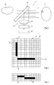
- the figure 1 illustrates, schematically, the operation of a head-up viewfinder 5.
- a semi-transparent plate 10 is placed between the eye of a user 12 and a scene to be observed 14.
- the objects of the scene to be observed 14 are generally located at infinity or at a significant distance from the observer 12.
- the semi-transparent plate 10 is inclined at an angle of 45 ° with respect to an axis connecting the scene 14 and the observer 12. The plate 10 makes it possible to transmit the information coming from the scene 14 to the observer 12, without alter this information.
- a projection system 15 is provided to project an image seen by the observer 12 at the same distance as the real image of the scene 14 and superimpose it on it.
- This system comprises a display screen 16 located at the focal point object of an optical system 18.
- the display screen 16 is controlled by a display screen control module 20 which determines the images to be displayed by example from signals provided by unrepresented sensors.
- the projection system 15 is placed perpendicularly to the axis connecting the scene 14 and the observer 12 so that the beam coming from the optical system 18 reaches the semi-transparent plate 10 perpendicular to this axis.
- the beam coming from the optical system 18 thus reaches the semi-transparent plate 10 at an angle of 45 ° with respect to its surface and is reflected towards the observer 12.
- the image displayed on the screen 16 is collimated to infinity by the optical system 18.
- the observer 12 does not have to make accommodation effort, which limits the visual fatigue of the latter.
- the semi-transparent plate 10 combines the image of the scene 14 and the image from the projection system 15, whereby the observer 12 displays an image comprising the projected image superimposed on the image of the image. scene 14.
- the display screen 16 may be a matrix screen. It can be a monochrome screen or a color screen. The smallest element of a digital image that can be displayed by the matrix screen 16 is called the image pixel. The smallest element of the screen 16 is called a display pixel to display an image. For a color screen, the display of an image pixel may require several display pixels, for example red, green and blue display pixels. The display pixels of a matrix screen are regularly divided into rows and columns. A monochrome display screen 16 comprises, for example, between 300 and 1000 rows and 300 and 1000 columns. For the image display generally having a circular shape, screens having substantially the same number of rows and columns can advantageously be used.
- the matrix display screen 16 is, for example, a liquid crystal display (LCD). It may also be a light-emitting diode screen, for example organic light-emitting diodes or OLED (Organic Light-Emitting Diode).
- LCD liquid crystal display
- OLED Organic Light-Emitting Diode
- the figure 2 represents an exemplary matrix display screen 16 comprising display pixels 22 divided into 16 rows and 16 columns.
- an activated display pixel that is to say, projecting a signal bright, by a black square
- a display pixel not activated that is to say not projecting a light signal, by a white square.
- the image provided by the display screen 16 in a head-up display is a relatively simple image including useful information for the observer 12, including the information provided by on-board instruments.
- These images can, to a large extent, be formed from line segments.
- two segments 24, 26 are represented in figure 2 .
- the segment 24 is a segment obtained by the activation of adjacent display pixels of the same row R of the screen 16 and the segment 26 is obtained by the activation of adjacent display pixels of the same column C .
- the screen 16, the optical system 18 and the semi-transparent plate 10 are, in a conventional manner, arranged relative to each other so that the segment 24 is perceived as being horizontal by the observer 12 and that the segment 26 is perceived as being vertical by the observer 12.
- a disadvantage of the projection system 15 described above is as follows: for some applications, especially when the head-up display equips the cockpit of an aircraft, visual information representing the artificial horizon is displayed.
- the artificial horizon is usually represented by the display of one or more line segments.
- the segment representing the artificial horizon is horizontal, which may correspond to segment 24 of the figure 2 , and when the roll angle of the aircraft is not zero, the segment is displayed inclined with respect to the horizontal direction.
- the roll angle nevertheless tends to oscillate slightly around zero. This results in slight oscillations of the segment representing the artificial horizon with respect to the horizontal direction.
- FIG. figure 3 a portion of the screen on which is displayed the level of an artificial horizon slightly inclined with respect to the horizontal direction, is schematically represented.
- the artificial horizon is represented by several adjacent groups of adjacent pixels of different and adjacent rows, two groups 28, 30 being represented in FIG. figure 3 . Since the groups 28, 30 can have a large number of pixels, the observer 12 does not perceive the level of the horizon as a continuous segment, but as a series of bearings, which is uncomfortable. In addition, a small variation of the roll angle can cause a large displacement of the groups of pixels 28, 30 activated, which is also uncomfortable.
- the use of the screen 16, as represented in figure 2 has, in addition, another disadvantage, described below, when the screen is light-emitting diodes, for example organic light-emitting diodes.
- the figure 4 represents, partially and schematically, an exemplary embodiment of a display pixel 22 of an OLED matrix screen.
- Each display pixel 22 comprises an organic light-emitting diode 32, two field-effect transistors TFT 1 and TFT 2 , for example thin-film transistors, and a capacitor C S.
- the cathode of the diode 32 is connected to a cathode electrode V C which may be common to all the display pixels 22 of the screen.
- a V SELECTION selection line is connected to the gate of the TFT transistor 1 of all the display pixels of the row.
- a transmission line of a data signal V DATA is connected to one of the conduction terminals of the TFT transistor 1 of each display pixel of the column.
- the other conduction terminal of the TFT transistor 1 is connected to an armature of the capacitor C S and to the gate of the transistor TFT 2 .
- a supply line V DD is connected, for each display pixel 22 of the column, to the other armature of the capacitor C S and to a conduction terminal of the transistor TFT 2 , the other conduction terminal of the TFT transistor 2 being connected to the anode of the diode 32.
- the diode 32 Upon activation of the display pixel 22, the diode 32 is traversed by a current transmitted by the supply line V DD and whose intensity depends on the desired radiation of the display pixel.
- the luminance of the activated display pixels of the screen 16 be at least 40000 candelas / m 2 .
- adjacent display pixels of the same column must be activated simultaneously.
- a disadvantage of the matrix screen 16 is that the supply line V DD is connected to all the display pixels 22 of the same column.
- the total current to flow in the supply line V DD may be greater than several milliamperes. This imposes considerable constraints when designing the display screen 16 on the dimensions of the metal tracks used to make the supply lines V DD to ensure that the supply lines V DD can suitably transport such currents.
- an object of an embodiment is to provide a head-up viewfinder comprising a matrix display screen at least partially overcoming some of the disadvantages of existing systems.
- Another object of an embodiment is that the perception comfort of the visual information projected by the head-up display is improved.
- Another object of an embodiment is that the intensity peaks of the currents implemented during the operation of the matrix screen are reduced.
- the head-up display can be implemented with a display screen.
- liquid crystal or a light-emitting diode screen in particular organic light-emitting diodes.
- the present invention aims at modifying the position of the display screen 16 with respect to the optical system 18 and / or the semi-transparent plate 10 with respect to the conventional position of the display screen 16 for which the observer 12 sees a horizontal (or possibly vertical) segment when adjacent display pixels of the same row of the screen 16 are activated.
- the present invention consists in orienting the display screen 16 with respect to the optical system 18 and the semi-transparent plate 10 so that the observer 12 does not see a horizontal (or vertical) segment when the display pixels of a row of the display screen are activated but a segment inclined with respect to the horizontal direction of an inclination angle ⁇ . Similarly, the observer 12 does not see a vertical (or horizontal) segment when the display pixels of a column of the display screen are activated but a segment inclined with respect to the vertical direction of a angle of inclination ⁇ .
- the angle of inclination ⁇ is preferably between 15 ° and 60 °, more preferably between 18 ° and 45 °, even more preferably between 20 ° and 30 °, for example of the order of 27 °.
- this can be obtained by rotating the display screen 16, around the optical axis of the optical system 18, the inclination angle ⁇ from the conventional position of the screen 16.
- display pixels of the screen 16 belonging to different rows and columns must be activated to display an element that is perceived by the observer 12 as being oriented in the horizontal direction.
- An example of such an element 40 is shown in figure 5 and comprises four groups 42 of two pixels belonging to four different rows.
- display pixels of the screen belonging to different rows and columns must be activated to display an element that is perceived by the observer 12 as being oriented in the vertical direction.
- An example of such an element 44 is shown in figure 5 and comprises four groups 46 of two pixels belonging to four different columns.
- the display of a perfectly horizontal element or of an almost horizontal element corresponds, in both cases, to the activation of groups of display pixels, for example each comprising between 5 and 20 display pixels. belonging to at least two rows and several different columns.
- the number and position of the groups of display pixels and the number of display pixels per group of display pixels change little during the transition between the display of a perfectly horizontal element and the display of a almost horizontal element. As a result, this transition is perceived more fluidly by the observer 12, which makes it more comfortable.
- the currents carried by the conductive tracks associated with the columns of a light emitting diode display screen are reduced when displaying a vertical element since display pixels belonging to several different columns are then activated.
- control module 20 is adapted to directly supply digital images adapted to an inclined display screen of the angle of inclination ⁇ .
- the digital images to be displayed correspond to first digital images adapted to a display screen arranged according to the conventional position described above.
- the module display 20 can, for each first digital image to be displayed, determine a second digital image corresponding to the first digital image to which is applied a mathematical transformation corresponding to a rotation of an angle equal to the opposite of the angle d ⁇ inclination taking, for example, as the center of rotation, the center of the first digital image.
- the module 20 controls the screen 16 for displaying the second digital image.
- the module 20 controls the screen 16 for displaying the first digital image by transmitting control signals adapted to the screen 16 and the activation circuit of the display pixels 22 of the display screen.
- display 16 includes circuitry for modifying the control signals so as to display a second digital image corresponding to the rotation of the first image by an angle opposite the angle of inclination ⁇ .
- the information to be displayed is located in a circle whose center is the center of the display screen and whose radius corresponds to half the width or height of the display screen.
- all the information to be displayed is also present in the final digital image. There is no lost information.
- the application of the angle rotation - ⁇ can be carried out by digital processing by the control module 20.
- the application of the angle rotation - ⁇ to the digital image can be carried out directly by the selection circuits of the display screen.
- the figure 6 is a block diagram of a computing device 1000 that can be used to realize the control module 20.
- the computing device 1000 may comprise one or more processors 1001 (Processor (s)) and one or more non-storage media.
- computer-readable transient for example, memory 1003 (memory)
- the memory 1003 can storing, in a computer-readable non-transitory storage means, computer program instructions which, when executed, implement the previously described functions performed by the control module 20.
- the processor or the processors 1001 can be coupled to memory 1003 and may execute these computer program instructions to cause the performance of these functions.
- the computing device 1000 may also comprise a network input / output interface 1005 (Network I / O Interface (s)) by which the computing device can communicate with other computing devices (for example, over a network). ), and may also include one or more user interfaces 1007 (User I / O Interface (s)), through which the computing device can provide output signals to a user and receive input signals. from the user.
- User interfaces may include devices such as a keyboard, mouse, microphone, display device (eg monitor or touch screen), speakers, camera, and / or various other types of input / output device.
- the embodiments described above can be implemented in several ways.
- the embodiments may be implemented using a dedicated circuit, a software or a combination thereof.
- the software code can be executed on any appropriate processor (for example, a microprocessor) or a set of processors, whether provided in a single computing device or distributed between several computing devices.
- any component or set of components that performs the functions described above may be considered as one or more controllers that control the functions described above.
- the controller or the controllers can be implemented in many ways, for example with a dedicated electronic circuit or with a general purpose circuit (eg for example, one or more processors) that is programmed using software or firmware to perform the process steps described above.
- an embodiment described herein comprises at least one computer readable storage medium (RAM, ROM, EEPROM, flash memory or other memory technology, CD-ROM, digital versatile disk ( DVD) or other optical disk carrier, magnetic cassette, magnetic tape, magnetic storage disk or other magnetic storage device, or other computer-readable non-transitory storage medium) encoded with a computer program (c) that is, several executable instructions) which, when executed on one or more processors, performs the functions of the previously described embodiments.
- the computer readable medium can be transportable so that the program stored thereon can be loaded onto any computing device to implement aspects of the techniques described herein.
- references to a computer program which, when executed, performs any of the functions described above is not limited to an application program running on a computer. host.
- the terms computer program and software are used herein in a general sense to refer to any type of computer code (e.g., application software, firmware, microcode, or any other form of instruction computer) that can be used to program one or more processors to implement aspects of the techniques described herein.
- the semi-transparent blade of the viewfinder can be part of the windshield of the motor vehicle.
- the semitransparent blade of the viewfinder can be part of the visor of the helmet.
Landscapes
- Physics & Mathematics (AREA)
- General Physics & Mathematics (AREA)
- Optics & Photonics (AREA)
- Control Of Indicators Other Than Cathode Ray Tubes (AREA)
- Control Of El Displays (AREA)
- Instrument Panels (AREA)
- Controls And Circuits For Display Device (AREA)
Abstract
Description
- La présente description concerne un viseur tête haute, encore appelé afficheur tête haute, collimateur tête haute ou système de visualisation tête haute, comprenant un écran d'affichage matriciel.
- Les viseurs tête haute, encore connus sous le sigle HUD, de l'anglais Head-Up Display, sont des systèmes d'affichage en réalité augmentée qui permettent d'intégrer une information visuelle sur une scène réelle vue par un observateur. En pratique, de tels systèmes peuvent être placés dans la visière d'un casque, dans le cockpit d'un avion ou au sein de l'habitacle d'un véhicule. Ils sont ainsi positionnés à faible distance des yeux de l'utilisateur, par exemple à quelques centimètres ou dizaines de centimètres.
- Les informations visuelles sont fournies par un écran d'affichage. De façon classique, il s'agit d'un écran à tube cathodique, en général à affichage vectoriel. La tendance actuelle est de remplacer les écrans à tube cathodique des viseurs à tête haute par des écrans d'affichage matriciel à cristaux liquides ou à diodes électroluminescentes.
- Toutefois, lorsqu'une ligne quasiment horizontale mais non parfaitement horizontale doit être affichée sur un écran matriciel, l'observateur perçoit de façon nette une ligne brisée très saccadée, ce qui est inconfortable. En outre, pour certains types d'écrans matriciels, notamment à diodes électroluminescentes organiques, l'affichage d'une ligne verticale sur l'écran peut entraîner des appels de courant importants. Ceci peut rendre difficile l'utilisation des écrans matriciels dans les viseurs tête haute.
- Ainsi, un mode de réalisation prévoit un viseur tête haute comprenant un écran d'affichage matriciel comprenant des pixels d'affichage agencés en rangées et en colonnes, dans lequel l'écran d'affichage est pivoté, autour d'un axe perpendiculaire à l'écran, d'un angle d'inclinaison compris entre 10 et 80 degrés, par rapport à la position de l'écran d'affichage pour laquelle un groupe de pixels d'affichage adjacents activés d'une même rangée apparaît à un observateur orienté selon la direction horizontale ou verticale.
- Selon un mode de réalisation, l'écran est un écran à diodes électroluminescentes.
- Selon un mode de réalisation, l'écran est un écran à diodes électroluminescentes organiques.
- Selon un mode de réalisation, l'écran est un écran à cristaux liquides.
- Selon un mode de réalisation, le viseur comprend un module de commande de l'écran d'affichage adapté à déterminer une première image numérique comprenant une matrice de pixels d'image, à déterminer une deuxième image numérique à partir de la première image numérique, la deuxième image correspondant à la rotation de la première image d'un angle opposé à l'angle d'inclinaison et à commander l'affichage de la deuxième image sur l'écran d'affichage.
- Selon un mode de réalisation, l'écran d'affichage comprend un circuit d'activation des pixels d'affichage, le viseur comprenant, en outre, un module de commande de l'écran d'affichage adapté à déterminer une première image numérique comprenant une matrice de pixels d'image et à fournir des signaux de commande au circuit d'activation pour l'affichage de la première image, le circuit d'activation étant adapté à modifier les signaux de commande pour l'affichage d'une deuxième image numérique correspondant à la rotation de la première image d'un angle opposé à l'angle d'inclinaison.
- Selon un mode de réalisation, l'angle d'inclinaison est compris entre 15 et 40 degrés par rapport à la direction horizontale ou verticale.
- Selon un mode de réalisation, l'angle d'inclinaison est compris entre 20 et 30 degrés par rapport à la direction horizontale ou verticale.
- Selon un mode de réalisation, le viseur comprend, en outre, une lame semi-transparente sur laquelle sont projetées les images fournies par l'écran d'affichage.
- Selon un mode de réalisation, le viseur comprend, en outre, un système optique adapté à collimater à l'infini l'image affichée sur l'écran d'affichage.
- Ces caractéristiques et avantages, ainsi que d'autres, sont exposés en détail dans la description suivante de modes de réalisation particuliers faite à titre non limitatif en relation avec les figures jointes parmi lesquelles :
- la
figure 1 représente, sous la forme d'un schéma-bloc, un exemple de viseur tête haute ; - la
figure 2 représente, de façon schématique, un écran matriciel classique sur lequel sont affichés un segment horizontal et un segment vertical ; - la
figure 3 représente une partie d'un écran matriciel classique sur lequel est affiché un segment quasi-horizontal ; - la
figure 4 représente, de façon partielle et schématique, un exemple de pixel d'affichage d'un écran matriciel à diodes électroluminescentes organiques ; - la
figure 5 représente un exemple d'écran matriciel selon un mode de réalisation ; et - la
figure 6 représente, sous la forme d'un schéma-bloc, un mode de réalisation du module de commande de lafigure 1 . - Par souci de clarté, de mêmes éléments ont été désignés par de mêmes références aux différentes figures et, de plus, comme cela est habituel dans la représentation des circuits, les diverses figures ne sont pas tracées à l'échelle.
- Dans la suite de la description, sauf indication contraire, les termes "quasiment", "sensiblement", "environ" et "de l'ordre de" signifient "à 10 % près".
- La
figure 1 illustre, de façon schématique, le fonctionnement d'un viseur tête haute 5. - Une lame semi-transparente 10 est placée entre l'oeil d'un utilisateur 12 et une scène à observer 14. Les objets de la scène à observer 14 sont généralement situés à l'infini ou à une distance importante de l'observateur 12. La lame semi-transparente 10 est inclinée selon un angle de 45° par rapport un axe reliant la scène 14 et l'observateur 12. La lame 10 permet de transmettre les informations provenant de la scène 14 à destination de l'observateur 12, sans altérer ces informations.
- Un système de projection 15 est prévu pour projeter une image vue par l'observateur 12 à la même distance que l'image réelle de la scène 14 et la superposer à celle-ci. Ce système comprend un écran d'affichage 16 situé au point focal objet d'un système optique 18. L'écran d'affichage 16 est commandé par un module de commande d'écran d'affichage 20 qui détermine les images à afficher, par exemple à partir de signaux fournis par des capteurs non représentés.
- Le système de projection 15 est placé perpendiculairement à l'axe reliant la scène 14 et l'observateur 12 de façon que le faisceau issu du système optique 18 atteigne la lame semi-transparente 10 perpendiculairement à cet axe. Le faisceau issu du système optique 18 atteint ainsi la lame semi-transparente 10 avec un angle de 45° par rapport à sa surface et est réfléchi vers l'observateur 12. L'image affichée sur l'écran 16 est collimatée à l'infini par le système optique 18. L'observateur 12 n'a pas à faire d'effort d'accommodation, ce qui limite la fatigue visuelle de ce dernier. La lame semi-transparente 10 combine l'image de la scène 14 et l'image issue du système de projection 15, d'où il résulte que l'observateur 12 visualise une image comprenant l'image projetée superposée à l'image de la scène 14.
- L'écran d'affichage 16 peut être un écran matriciel. Il peut s'agir d'un écran monochrome ou d'un écran couleur. On appelle pixel d'image le plus petit élément d'une image numérique susceptible d'être affichée par l'écran matriciel 16. On appelle pixel d'affichage le plus petit élément de l'écran 16 pour afficher une image. Pour un écran couleur, l'affichage d'un pixel d'image peut nécessiter plusieurs pixels d'affichage, par exemple des pixels d'affichage rouge, vert et bleu. Les pixels d'affichage d'un écran matriciel sont régulièrement répartis en rangées et en colonnes. Un écran d'affichage 16 monochrome comprend, par exemple, entre 300 et 1000 rangées et 300 et 1000 colonnes. Pour l'affichage d'image ayant globalement une forme circulaire, des écrans présentant sensiblement le même nombre de rangées et de colonnes peuvent avantageusement être utilisés. L'écran d'affichage matriciel 16 est, par exemple, un écran à cristaux liquides ou LCD (sigle anglais pour Liquid Crystal Display). Il peut s'agir également d'un écran à diodes électroluminescentes, par exemple à diodes électroluminescentes organiques ou OLED (sigle anglais pour Organic Light-Emitting Diode).
- La
figure 2 représente un exemple d'écran d'affichage matriciel 16 comprenant des pixels d'affichage 22 répartis en 16 rangées et en 16 colonnes. On a représenté de façon schématique un pixel d'affichage activé, c'est-à-dire projetant un signal lumineux, par un carré noir et un pixel d'affichage non activé, c'est-à-dire ne projetant pas de signal lumineux, par un carré blanc. De façon générale, l'image fournie par l'écran d'affichage 16 dans un viseur tête haute est une image relativement simple comprenant des informations utiles pour l'observateur 12, notamment les informations fournies par des instruments de bord. Ces images peuvent, dans une large mesure, être formées à partir de segments de droite. A titre d'exemple, deux segments 24, 26 sont représentés enfigure 2 . Le segment 24 est un segment obtenu par l'activation de pixels d'affichage adjacents d'une même rangée R de l'écran 16 et le segment 26 est obtenu par l'activation de pixels d'affichage adjacents d'une même colonne C. - L'écran 16, le système optique 18 et la lame semi-transparente 10 sont, de façon classique, agencés les uns par rapport aux autres de façon que le segment 24 soit perçu comme étant horizontal par l'observateur 12 et que le segment 26 soit perçu comme étant vertical par l'observateur 12.
- Un inconvénient du système de projection 15 décrit précédemment est le suivant : pour certaines applications, notamment lorsque le viseur tête haute équipe le cockpit d'un avion, une information visuelle représentant l'horizon artificiel est affichée. L'horizon artificiel est généralement représenté par l'affichage d'un ou de plusieurs segments de droite. Lorsque l'angle de roulis de l'avion est nul, le segment représentant l'horizon artificiel est horizontal, ce qui peut correspondre au segment 24 de la
figure 2 , et lorsque l'angle de roulis de l'avion n'est pas nul, le segment est affiché de façon inclinée par rapport à la direction horizontale. En pratique, même lorsque l'avion est dans une phase de vol stabilisé, l'angle de roulis tend néanmoins à osciller légèrement autour de zéro. Ceci se traduit par de légères oscillations du segment représentant l'horizon artificiel par rapport à la direction horizontale. - En
figure 3 , on a représenté, de façon schématique, une partie de l'écran sur lequel est affiché le niveau d'un horizon artificiel légèrement incliné par rapport à la direction horizontale. L'horizon artificiel est représenté par plusieurs groupes jointifs de pixels adjacents de rangées différentes et adjacentes, deux groupes 28, 30 étant représentés enfigure 3 . Les groupes 28, 30 pouvant avoir un nombre important de pixels, l'observateur 12 ne perçoit pas le niveau de l'horizon comme un segment continu, mais comme une suite de paliers, ce qui est inconfortable. En outre, une faible variation de l'angle de roulis peut entraîner un déplacement important des groupes de pixels 28, 30 activés, ce qui est également inconfortable. - L'utilisation de l'écran 16, tel que représenté en
figure 2 , présente, en outre, un autre inconvénient, décrit ci-après, lorsque l'écran est à diodes électroluminescentes, par exemple à diodes électroluminescentes organiques. - La
figure 4 représente, de façon partielle et schématique, un exemple de réalisation d'un pixel d'affichage 22 d'un écran matriciel OLED. Chaque pixel d'affichage 22 comprend une diode électroluminescente organique 32, deux transistors à effet de champ TFT1 et TFT2, par exemple des transistors à film mince, et un condensateur CS. La cathode de la diode 32 est reliée à une électrode de cathode VC qui peut être commune à tous les pixels d'affichage 22 de l'écran. Pour chaque rangée de l'écran, une ligne de sélection VSELECTION est connectée à la grille du transistor TFT1 de tous les pixels d'affichage de la rangée. Pour chaque colonne de l'écran, une ligne de transmission d'un signal de donnée VDATA est connectée à l'une des bornes de conduction du transistor TFT1 de chaque pixel d'affichage de la colonne. L'autre borne de conduction du transistor TFT1 est connectée à une armature du condensateur CS et à la grille du transistor TFT2. Pour chaque colonne de l'écran, une ligne d'alimentation VDD est connectée, pour chaque pixel d'affichage 22 de la colonne, à l'autre armature du condensateur CS et à une borne de conduction du transistor TFT2, l'autre borne de conduction du transistor TFT2 étant connectée à l'anode de la diode 32. - Lors de l'activation du pixel d'affichage 22, la diode 32 est traversée par un courant transmis par la ligne d'alimentation VDD et dont l'intensité dépend du rayonnement souhaité du pixel d'affichage. Pour que l'observateur 12 puisse voir de façon convenable les informations visuelles affichées par le viseur tête haute, il est souhaitable que la luminance des pixels d'affichage activés de l'écran 16 soit au moins de 40000 candelas/m2. Pour afficher un segment vertical, par exemple le segment 26 représenté en
figure 2 , des pixels d'affichage adjacents d'une même colonne doivent être activés simultanément. Un inconvénient de l'écran matriciel 16 est que la ligne d'alimentation VDD est connectée à tous les pixels d'affichage 22 d'une même colonne. De ce fait, le courant total devant circuler dans la ligne d'alimentation VDD, pour l'activation simultanée d'un groupe de pixels d'affichage d'une même colonne, peut être supérieur à plusieurs milliampères. Cela impose de fortes contraintes lors de la conception de l'écran d'affichage 16 sur les dimensions des pistes métalliques utilisées pour réaliser les lignes d'alimentation VDD pour assurer que les lignes d'alimentation VDD puissent transporter de façon convenable de tels courants. - Ainsi, un objet d'un mode de réalisation est de prévoir un viseur tête haute comprenant un écran d'affichage matriciel palliant au moins en partie certains des inconvénients des systèmes existants.
- Un autre objet d'un mode de réalisation est que le confort de perception des informations visuelles projetées par le viseur tête haute est amélioré.
- Un autre objet d'un mode de réalisation est que les pics d'intensité des courants mis en oeuvre lors du fonctionnement de l'écran matriciel sont réduits.
- Un autre objet d'un mode de réalisation est que le viseur tête haute peut être mis en oeuvre avec un écran à cristaux liquides ou un écran à diodes électroluminescentes, notamment à diodes électroluminescentes organiques.
- La présente invention vise à modifier la position de l'écran d'affichage 16 par rapport au système optique 18 et/ou à la lame semi-transparente 10 par rapport à la position classique de l'écran d'affichage 16 pour laquelle l'observateur 12 voit un segment horizontal (ou éventuellement vertical) lorsque des pixels d'affichage adjacents d'une même rangée de l'écran 16 sont activés. La présente invention consiste à orienter l'écran d'affichage 16 par rapport au système optique 18 et à la lame semi-transparente 10 de sorte que l'observateur 12 ne voit pas un segment horizontal (ou vertical) lorsque les pixels d'affichage d'une rangée de l'écran d'affichage sont activés mais un segment incliné par rapport à la direction horizontale d'un angle d'inclinaison α. De façon analogue, l'observateur 12 ne voit pas un segment vertical (ou horizontal) lorsque les pixels d'affichage d'une colonne de l'écran d'affichage sont activés mais un segment incliné par rapport à la direction verticale d'un angle d'inclinaison α.
- L'angle d'inclinaison α est de préférence compris entre 15° et 60°, plus préférentiellement entre 18° et 45°, encore plus préférentiellement entre 20° et 30°, par exemple de l'ordre de 27°.
- Dans l'exemple de viseur tête haute 5 représenté en
figure 1 , ceci peut être obtenu en faisant pivoter l'écran d'affichage 16, autour de l'axe optique du système optique 18, de l'angle d'inclinaison α depuis la position classique de l'écran 16. - De ce fait, des pixels d'affichage de l'écran 16 appartenant à des rangées et à des colonnes différentes doivent être activés pour afficher un élément qui est perçu par l'observateur 12 comme étant orienté selon la direction horizontale. Un exemple d'un tel élément 40 est représenté en
figure 5 et comprend quatre groupes 42 de deux pixels appartenant à quatre rangées différentes. - De façon analogue, des pixels d'affichage de l'écran appartenant à des rangées et à des colonnes différentes doivent être activés pour afficher un élément qui est perçu par l'observateur 12 comme étant orienté selon la direction verticale. Un exemple d'un tel élément 44 est représenté en
figure 5 et comprend quatre groupes 46 de deux pixels appartenant à quatre colonnes différentes. - Les deux inconvénients décrits précédemment lorsque l'écran d'affichage 16 est dans la position classique ne sont plus présents.
- En effet, l'affichage d'un élément parfaitement horizontal ou d'un élément quasiment horizontal correspond, dans les deux cas, à l'activation de groupes de pixels d'affichage, par exemple comprenant chacun entre 5 et 20 pixels d'affichage appartenant à au moins deux rangées et à plusieurs colonnes différentes. Le nombre et la position des groupes de pixels d'affichage et le nombre de pixels d'affichage par groupe de pixels d'affichage changent peu lors de la transition entre l'affichage d'un élément parfaitement horizontal et l'affichage d'un élément quasiment horizontal. De ce fait, cette transition est perçue de façon plus fluide par l'observateur 12, ce qui la rend plus confortable.
- En outre, les courants acheminés par les pistes conductrices associées aux colonnes d'un écran d'affichage à diodes électroluminescentes sont réduits lors de l'affichage d'un élément vertical puisque des pixels d'affichage appartenant à plusieurs colonnes différentes sont alors activés.
- Selon un mode de réalisation, le module de commande 20 est adapté à fournir directement des images numériques adaptées à un écran d'affichage incliné de l'angle d'inclinaison α.
- Selon un autre mode de réalisation, les images numériques à afficher, qui sont déterminées ou reçues par le module de commande 20, correspondent à des premières images numériques adaptées à un écran d'affichage disposé selon la position classique décrite précédemment. Dans ce cas, le module d'affichage 20 peut, pour chaque première image numérique à afficher, déterminer une deuxième image numérique correspondant à la première image numérique à laquelle est appliquée une transformation mathématique correspondant à une rotation d'un angle égal à l'opposé de l'angle d'inclinaison α en prenant, par exemple, comme centre de rotation, le centre de la première image numérique. Le module 20 commande alors l'écran 16 pour l'affichage de la deuxième image numérique.
- Selon une variante, le module 20 commande l'écran 16 pour l'affichage de la première image numérique en transmettant des signaux de commande adaptés à l'écran 16 et le circuit d'activation des pixels d'affichage 22 de l'écran d'affichage 16 comprend des circuits pour modifier les signaux de commande de façon à afficher une deuxième image numérique correspondant à la rotation de la première image d'un angle opposé à l'angle d'inclinaison α.
- De façon générale, les informations à afficher sont situées dans un cercle dont le centre est le centre de l'écran d'affichage et dont le rayon correspond à la moitié de la largeur ou de la hauteur de l'écran d'affichage. De ce fait, après l'application d'une transformation mathématique correspondant à une rotation d'angle opposé à l'angle d'inclinaison α, toutes les informations à afficher sont également présentes dans l'image numérique finale. Il n'y a donc pas d'information perdue. L'application de la rotation d'angle -α peut être réalisée par traitement numérique par le module de commande 20. A titre de variante, l'application de la rotation d'angle -α à l'image numérique peut être réalisée directement par les circuits de sélection de l'écran d'affichage.
- La
figure 6 est un schéma-bloc d'un dispositif de calcul 1000 qui peut être utilisé pour réaliser le module de commande 20. Le dispositif de calcul 1000 peut comprendre un ou plusieurs processeurs 1001 (Processor(s)) et un ou plusieurs supports de stockage non transitoire lisibles par ordinateur (par exemple, la mémoire 1003 (Memory)). La mémoire 1003 peut stocker, dans un moyen de stockage non transitoire lisible par ordinateur, des instructions de programme informatique qui, lorsqu'elles sont exécutées, mettent en oeuvre les fonctions décrites précédemment réalisées par le module de commande 20. Le processeur ou les processeurs 1001 peuvent être couplés à la mémoire 1003 et peuvent exécuter ces instructions de programme d'ordinateur pour entraîner la réalisation de ces fonctions. - Le dispositif de calcul 1000 peut également comprendre une interface 1005 d'entrée/sortie de réseau (Network I/O Interface(s)) par laquelle le dispositif de calcul peut communiquer avec d'autres dispositifs de calcul (par exemple, sur un réseau), et peut également comprendre une ou plusieurs interfaces d'utilisateur 1007 (User I/O Interface(s)), par l'intermédiaire desquelles le dispositif de calcul peut fournir des signaux de sortie à un utilisateur et recevoir des signaux d'entrée provenant de l'utilisateur. Les interfaces d'utilisateur peuvent comprendre des périphériques tels qu'un clavier, une souris, un microphone, un périphérique d'affichage (p.ex. un moniteur ou un écran tactile), des haut-parleurs, une caméra, et/ou divers autres types de périphérique entrée/sortie.
- Les modes de réalisation décrits précédemment peuvent être mis en oeuvre de plusieurs façons. A titre d'exemple, les modes de réalisation peuvent être mis en oeuvre à l'aide d'un circuit dédié, d'un logiciel ou d'une combinaison de ceux-ci. Lorsqu'ils sont mis en oeuvre par logiciel, le code logiciel peut être exécuté sur n'importe quel processeur approprié (par exemple, un microprocesseur) ou un ensemble de processeurs, qu'ils soient prévus dans un dispositif de calcul unique ou répartis entre plusieurs dispositifs de calcul. Il convient de noter que tout composant ou ensemble de composants qui réalise les fonctions décrites précédemment peut être considéré comme un ou plusieurs contrôleurs qui commandent les fonctions décrites précédemment. Le contrôleur ou les contrôleurs peuvent être mis en oeuvre de nombreuses façons, par exemple avec un circuit électronique dédié ou avec un circuit à usage général (par exemple, un ou plusieurs processeurs) qui est programmé à l'aide d'un logiciel ou d'un microcode pour exécuter les étapes de procédé décrites ci-dessus.
- À cet égard, il convient de noter qu'un mode de réalisation décrit ici comprend au moins un support de stockage lisible par ordinateur (RAM, ROM, EEPROM, mémoire flash ou une autre technologie de mémoire, CD-ROM, disque numérique polyvalent (DVD) ou un autre support à disque optique, cassette magnétique, bande magnétique, disque de stockage magnétique ou un autre dispositif de stockage magnétique, ou un autre support de stockage non transitoire lisible par ordinateur) codé avec un programme d'ordinateur (c'est-à-dire plusieurs instructions exécutables) qui, lorsqu'il est exécuté sur un processeur ou plusieurs processeurs, effectue les fonctions des modes de réalisation décrits précédemment. Le support lisible par ordinateur peut être transportable de sorte que le programme stocké sur celui-ci peut être chargé sur n'importe quel dispositif de calcul pour mettre en oeuvre des aspects des techniques décrites ici. En outre, il convient de noter que la référence à un programme d'ordinateur qui, lorsqu'il est exécuté, effectue l'une quelconque des fonctions décrites précédemment, ne se limite pas à un programme d'application s'exécutant sur un ordinateur hôte. Au contraire, les termes programme d'ordinateur et logiciel sont utilisés ici dans un sens général pour faire référence à tout type de code informatique (par exemple, un logiciel d'application, un mircrologiciel, un microcode, ou toute autre forme d'instruction d'ordinateur) qui peut être utilisé pour programmer un ou plusieurs processeurs pour mettre en oeuvre des aspects des techniques décrites ici.
- Des modes de réalisation particuliers ont été décrits. Diverses variantes et modifications apparaîtront à l'homme de l'art. En particulier, dans le cas d'une application dans le domaine automobile, la lame semi-transparente du viseur peut faire partie du pare-brise du véhicule automobile. En outre, dans le cas d'un viseur tête haute équipant un casque, la lame semi-transparente du viseur peut faire partie de la visière du casque.
Claims (10)
- Viseur tête haute (5) comprenant un écran d'affichage matriciel (16) comprenant des pixels d'affichage (22) agencés en rangées et en colonnes, dans lequel l'écran d'affichage est pivoté, autour d'un axe perpendiculaire à l'écran, d'un angle d'inclinaison (α) compris entre 10 et 80 degrés, par rapport à la position de l'écran d'affichage pour laquelle un groupe de pixels d'affichage adjacents activés d'une même rangée apparaît à un observateur (12) orienté selon la direction horizontale ou verticale.
- Viseur tête haute selon la revendication 1, dans lequel l'écran (16) est un écran à diodes électroluminescentes (32).
- Viseur tête haute selon la revendication 2, dans lequel l'écran (16) est un écran à diodes électroluminescentes organiques (32).
- Viseur tête haute selon la revendication 1, dans lequel l'écran (16) est un écran à cristaux liquides.
- Viseur tête haute selon l'une quelconque des revendications 1 à 4, comprenant un module (20) de commande de l'écran d'affichage (16) adapté à déterminer une première image numérique comprenant une matrice de pixels d'image, à déterminer une deuxième image numérique à partir de la première image numérique, la deuxième image correspondant à la rotation de la première image d'un angle opposé à l'angle d'inclinaison et à commander l'affichage de la deuxième image sur l'écran d'affichage.
- Viseur tête haute selon l'une quelconque des revendications 1 à 4, dans lequel l'écran d'affichage (16) comprend un circuit d'activation des pixels d'affichage (22), le viseur comprenant, en outre, un module (20) de commande de l'écran d'affichage (16) adapté à déterminer une première image numérique comprenant une matrice de pixels d'image et à fournir des signaux de commande au circuit d'activation pour l'affichage de la première image, le circuit d'activation étant adapté à modifier les signaux de commande pour l'affichage d'une deuxième image numérique correspondant à la rotation de la première image d'un angle opposé à l'angle d'inclinaison.
- Viseur tête haute selon l'une quelconque des revendications 1 à 6, dans lequel l'angle d'inclinaison (α) est compris entre 15 et 40 degrés par rapport à la direction horizontale ou verticale.
- Viseur tête haute selon l'une quelconque des revendications 1 à 7, dans lequel l'angle d'inclinaison (α) est compris entre 20 et 30 degrés par rapport à la direction horizontale ou verticale.
- Viseur tête haute selon l'une quelconque des revendications 1 à 8, comprenant, en outre, une lame semi-transparente (10) sur laquelle sont projetées les images fournies par l'écran d'affichage (16).
- Viseur tête haute selon l'une quelconque des revendications 1 à 9, comprenant, en outre, un système optique (18) adapté à collimater à l'infini l'image affichée sur l'écran d'affichage (16).
Applications Claiming Priority (1)
| Application Number | Priority Date | Filing Date | Title |
|---|---|---|---|
| FR1261399A FR2998681B1 (fr) | 2012-11-29 | 2012-11-29 | Viseur tete haute a confort de visualisation ameliore |
Publications (2)
| Publication Number | Publication Date |
|---|---|
| EP2738589A1 true EP2738589A1 (fr) | 2014-06-04 |
| EP2738589B1 EP2738589B1 (fr) | 2015-09-16 |
Family
ID=47628252
Family Applications (1)
| Application Number | Title | Priority Date | Filing Date |
|---|---|---|---|
| EP13194766.5A Not-in-force EP2738589B1 (fr) | 2012-11-29 | 2013-11-28 | Viseur tête haute à confort de visualisation amélioré |
Country Status (5)
| Country | Link |
|---|---|
| US (1) | US9829705B2 (fr) |
| EP (1) | EP2738589B1 (fr) |
| JP (1) | JP6315956B2 (fr) |
| KR (1) | KR102072182B1 (fr) |
| FR (1) | FR2998681B1 (fr) |
Families Citing this family (1)
| Publication number | Priority date | Publication date | Assignee | Title |
|---|---|---|---|---|
| JP6604284B2 (ja) * | 2016-07-21 | 2019-11-13 | オムロン株式会社 | 表示装置 |
Citations (2)
| Publication number | Priority date | Publication date | Assignee | Title |
|---|---|---|---|---|
| US4591844A (en) * | 1982-12-27 | 1986-05-27 | General Electric Company | Line smoothing for a raster display |
| US20070097140A1 (en) * | 2005-10-28 | 2007-05-03 | Fenney Simon J | Full screen anti-aliasing with dynamic filters |
Family Cites Families (15)
| Publication number | Priority date | Publication date | Assignee | Title |
|---|---|---|---|---|
| US6448944B2 (en) * | 1993-10-22 | 2002-09-10 | Kopin Corporation | Head-mounted matrix display |
| JPH07261727A (ja) * | 1994-03-25 | 1995-10-13 | Hitachi Ltd | 情報表示装置 |
| JPH07267195A (ja) * | 1994-03-31 | 1995-10-17 | Shimadzu Corp | 航空機の機体姿勢角表示方法 |
| JPH11196397A (ja) * | 1997-12-26 | 1999-07-21 | Canon Inc | 表示装置及び通信システム |
| JP2003216135A (ja) * | 2002-01-25 | 2003-07-30 | Fuji Photo Film Co Ltd | 情報表示装置 |
| JP3835612B2 (ja) * | 2003-06-27 | 2006-10-18 | 日本精機株式会社 | 表示装置 |
| JP5029876B2 (ja) * | 2007-01-26 | 2012-09-19 | 日本精機株式会社 | ヘッドアップディスプレイ装置 |
| JP5146906B2 (ja) * | 2007-11-28 | 2013-02-20 | 日本精機株式会社 | ヘッドアップディスプレイ装置 |
| KR100913103B1 (ko) * | 2008-05-07 | 2009-08-19 | 엘지전자 주식회사 | 헤드-업 디스플레이 시스템 |
| JP5161760B2 (ja) * | 2008-12-26 | 2013-03-13 | 株式会社東芝 | 車載用表示システム及び表示方法 |
| JP5316391B2 (ja) * | 2009-08-31 | 2013-10-16 | ソニー株式会社 | 画像表示装置及び頭部装着型ディスプレイ |
| US9052926B2 (en) * | 2010-04-07 | 2015-06-09 | Apple Inc. | Device, method, and graphical user interface for managing concurrently open software applications |
| US8692845B2 (en) * | 2010-10-28 | 2014-04-08 | Eastman Kodak Company | Head-mounted display control with image-content analysis |
| US8866852B2 (en) * | 2011-11-28 | 2014-10-21 | Google Inc. | Method and system for input detection |
| JP2012208498A (ja) * | 2012-05-21 | 2012-10-25 | Nec Corp | 液晶表示装置、移動体通信端末装置及び液晶表示方法 |
-
2012
- 2012-11-29 FR FR1261399A patent/FR2998681B1/fr not_active Expired - Fee Related
-
2013
- 2013-11-25 US US14/089,001 patent/US9829705B2/en not_active Expired - Fee Related
- 2013-11-25 KR KR1020130144047A patent/KR102072182B1/ko not_active Expired - Fee Related
- 2013-11-28 JP JP2013246408A patent/JP6315956B2/ja not_active Expired - Fee Related
- 2013-11-28 EP EP13194766.5A patent/EP2738589B1/fr not_active Not-in-force
Patent Citations (2)
| Publication number | Priority date | Publication date | Assignee | Title |
|---|---|---|---|---|
| US4591844A (en) * | 1982-12-27 | 1986-05-27 | General Electric Company | Line smoothing for a raster display |
| US20070097140A1 (en) * | 2005-10-28 | 2007-05-03 | Fenney Simon J | Full screen anti-aliasing with dynamic filters |
Non-Patent Citations (1)
| Title |
|---|
| ROBERT D ET AL: "High Resolution LCD Projector for Extra-Wide Field of View Head-Up Display", PROCEEDINGS OF SPIE - THE INTERNATIONAL SOCIETY FOR OPTICAL ENGINEERING, COCKPIT DISPLAYS X, vol. 5080, 22 April 2003 (2003-04-22), pages 320 - 329, XP055071659, DOI: 10.1117/12.485731 * |
Also Published As
| Publication number | Publication date |
|---|---|
| US20140145916A1 (en) | 2014-05-29 |
| JP2014132332A (ja) | 2014-07-17 |
| EP2738589B1 (fr) | 2015-09-16 |
| US9829705B2 (en) | 2017-11-28 |
| FR2998681B1 (fr) | 2015-01-30 |
| KR102072182B1 (ko) | 2020-01-31 |
| KR20140070404A (ko) | 2014-06-10 |
| FR2998681A1 (fr) | 2014-05-30 |
| JP6315956B2 (ja) | 2018-04-25 |
Similar Documents
| Publication | Publication Date | Title |
|---|---|---|
| US10685592B1 (en) | Near-eye display assembly with adjustable resolution and frame rate | |
| US20150029018A1 (en) | Articulating instrument cluster | |
| US20140327771A1 (en) | System, method, and computer program product for displaying a scene as a light field | |
| EP2212736B1 (fr) | Dispositif de surveillance croisée pour afficheurs dits tête haute | |
| US11226487B2 (en) | Display apparatus for vehicles and method of controlling the same | |
| US11900845B2 (en) | System and method for optical calibration of a head-mounted display | |
| US11048091B1 (en) | Wide-field image light and inset image light for head mounted displays | |
| US20220348080A1 (en) | Control of a display of an augmented reality head-up display apparatus for a motor vehicle | |
| EP4286917B1 (fr) | Réglage automatique de la hauteur de l'oeil | |
| US10276130B1 (en) | Display latency calibration for organic light emitting diode (OLED) display | |
| CN115516551A (zh) | 显示调整方法、装置、系统及存储介质 | |
| EP3482254B1 (fr) | Dispositif de génération d'images pour afficheur tête-haute et procédé de pilotage d'un tel dispositif | |
| EP2738589B1 (fr) | Viseur tête haute à confort de visualisation amélioré | |
| US20240363042A1 (en) | Head-up display with reduced obstruction | |
| US20240363041A1 (en) | Head-up display with reduced masking | |
| US20230300285A1 (en) | Dynamic binning passthrough content | |
| JP6607128B2 (ja) | 虚像表示装置、虚像表示方法および制御プログラム | |
| FR3104521A1 (fr) | Procédé et dispositif de contrôle d’affichage d’image dans un véhicule | |
| EP3440835B1 (fr) | Système d'affichage tête-haute | |
| FR3077636A1 (fr) | Procede de visualisation de l'attitude d'un aeronef, produit programme d'ordinateur et systeme de visualisation associes | |
| US12535885B2 (en) | Field-of-view adjustment based on display position | |
| US20240371304A1 (en) | Electronic device and method providing 3-dimension image | |
| US20260135985A1 (en) | Multiscopy using collimated backlight and dynamic beam steering | |
| US20250317547A1 (en) | Augmenting reality with multiscopic see-through display | |
| US20250244575A1 (en) | Telecentric virtual image projection system |
Legal Events
| Date | Code | Title | Description |
|---|---|---|---|
| PUAI | Public reference made under article 153(3) epc to a published international application that has entered the european phase |
Free format text: ORIGINAL CODE: 0009012 |
|
| 17P | Request for examination filed |
Effective date: 20131128 |
|
| AK | Designated contracting states |
Kind code of ref document: A1 Designated state(s): AL AT BE BG CH CY CZ DE DK EE ES FI FR GB GR HR HU IE IS IT LI LT LU LV MC MK MT NL NO PL PT RO RS SE SI SK SM TR |
|
| AX | Request for extension of the european patent |
Extension state: BA ME |
|
| R17P | Request for examination filed (corrected) |
Effective date: 20140620 |
|
| RBV | Designated contracting states (corrected) |
Designated state(s): AL AT BE BG CH CY CZ DE DK EE ES FI FR GB GR HR HU IE IS IT LI LT LU LV MC MK MT NL NO PL PT RO RS SE SI SK SM TR |
|
| GRAP | Despatch of communication of intention to grant a patent |
Free format text: ORIGINAL CODE: EPIDOSNIGR1 |
|
| INTG | Intention to grant announced |
Effective date: 20150413 |
|
| GRAS | Grant fee paid |
Free format text: ORIGINAL CODE: EPIDOSNIGR3 |
|
| GRAA | (expected) grant |
Free format text: ORIGINAL CODE: 0009210 |
|
| AK | Designated contracting states |
Kind code of ref document: B1 Designated state(s): AL AT BE BG CH CY CZ DE DK EE ES FI FR GB GR HR HU IE IS IT LI LT LU LV MC MK MT NL NO PL PT RO RS SE SI SK SM TR |
|
| REG | Reference to a national code |
Ref country code: GB Ref legal event code: FG4D Free format text: NOT ENGLISH |
|
| REG | Reference to a national code |
Ref country code: CH Ref legal event code: EP |
|
| REG | Reference to a national code |
Ref country code: IE Ref legal event code: FG4D Free format text: LANGUAGE OF EP DOCUMENT: FRENCH |
|
| REG | Reference to a national code |
Ref country code: AT Ref legal event code: REF Ref document number: 750231 Country of ref document: AT Kind code of ref document: T Effective date: 20151015 |
|
| REG | Reference to a national code |
Ref country code: DE Ref legal event code: R096 Ref document number: 602013003095 Country of ref document: DE |
|
| REG | Reference to a national code |
Ref country code: SE Ref legal event code: TRGR |
|
| REG | Reference to a national code |
Ref country code: FR Ref legal event code: PLFP Year of fee payment: 3 |
|
| REG | Reference to a national code |
Ref country code: NL Ref legal event code: MP Effective date: 20150916 |
|
| PG25 | Lapsed in a contracting state [announced via postgrant information from national office to epo] |
Ref country code: LV Free format text: LAPSE BECAUSE OF FAILURE TO SUBMIT A TRANSLATION OF THE DESCRIPTION OR TO PAY THE FEE WITHIN THE PRESCRIBED TIME-LIMIT Effective date: 20150916 Ref country code: GR Free format text: LAPSE BECAUSE OF FAILURE TO SUBMIT A TRANSLATION OF THE DESCRIPTION OR TO PAY THE FEE WITHIN THE PRESCRIBED TIME-LIMIT Effective date: 20151217 Ref country code: NO Free format text: LAPSE BECAUSE OF FAILURE TO SUBMIT A TRANSLATION OF THE DESCRIPTION OR TO PAY THE FEE WITHIN THE PRESCRIBED TIME-LIMIT Effective date: 20151216 Ref country code: LT Free format text: LAPSE BECAUSE OF FAILURE TO SUBMIT A TRANSLATION OF THE DESCRIPTION OR TO PAY THE FEE WITHIN THE PRESCRIBED TIME-LIMIT Effective date: 20150916 Ref country code: FI Free format text: LAPSE BECAUSE OF FAILURE TO SUBMIT A TRANSLATION OF THE DESCRIPTION OR TO PAY THE FEE WITHIN THE PRESCRIBED TIME-LIMIT Effective date: 20150916 |
|
| REG | Reference to a national code |
Ref country code: LT Ref legal event code: MG4D |
|
| REG | Reference to a national code |
Ref country code: AT Ref legal event code: MK05 Ref document number: 750231 Country of ref document: AT Kind code of ref document: T Effective date: 20150916 |
|
| PG25 | Lapsed in a contracting state [announced via postgrant information from national office to epo] |
Ref country code: HR Free format text: LAPSE BECAUSE OF FAILURE TO SUBMIT A TRANSLATION OF THE DESCRIPTION OR TO PAY THE FEE WITHIN THE PRESCRIBED TIME-LIMIT Effective date: 20150916 Ref country code: RS Free format text: LAPSE BECAUSE OF FAILURE TO SUBMIT A TRANSLATION OF THE DESCRIPTION OR TO PAY THE FEE WITHIN THE PRESCRIBED TIME-LIMIT Effective date: 20150916 |
|
| PG25 | Lapsed in a contracting state [announced via postgrant information from national office to epo] |
Ref country code: NL Free format text: LAPSE BECAUSE OF FAILURE TO SUBMIT A TRANSLATION OF THE DESCRIPTION OR TO PAY THE FEE WITHIN THE PRESCRIBED TIME-LIMIT Effective date: 20150916 |
|
| PG25 | Lapsed in a contracting state [announced via postgrant information from national office to epo] |
Ref country code: CZ Free format text: LAPSE BECAUSE OF FAILURE TO SUBMIT A TRANSLATION OF THE DESCRIPTION OR TO PAY THE FEE WITHIN THE PRESCRIBED TIME-LIMIT Effective date: 20150916 Ref country code: SK Free format text: LAPSE BECAUSE OF FAILURE TO SUBMIT A TRANSLATION OF THE DESCRIPTION OR TO PAY THE FEE WITHIN THE PRESCRIBED TIME-LIMIT Effective date: 20150916 Ref country code: EE Free format text: LAPSE BECAUSE OF FAILURE TO SUBMIT A TRANSLATION OF THE DESCRIPTION OR TO PAY THE FEE WITHIN THE PRESCRIBED TIME-LIMIT Effective date: 20150916 Ref country code: ES Free format text: LAPSE BECAUSE OF FAILURE TO SUBMIT A TRANSLATION OF THE DESCRIPTION OR TO PAY THE FEE WITHIN THE PRESCRIBED TIME-LIMIT Effective date: 20150916 Ref country code: IS Free format text: LAPSE BECAUSE OF FAILURE TO SUBMIT A TRANSLATION OF THE DESCRIPTION OR TO PAY THE FEE WITHIN THE PRESCRIBED TIME-LIMIT Effective date: 20160116 |
|
| PG25 | Lapsed in a contracting state [announced via postgrant information from national office to epo] |
Ref country code: PT Free format text: LAPSE BECAUSE OF FAILURE TO SUBMIT A TRANSLATION OF THE DESCRIPTION OR TO PAY THE FEE WITHIN THE PRESCRIBED TIME-LIMIT Effective date: 20160118 Ref country code: PL Free format text: LAPSE BECAUSE OF FAILURE TO SUBMIT A TRANSLATION OF THE DESCRIPTION OR TO PAY THE FEE WITHIN THE PRESCRIBED TIME-LIMIT Effective date: 20150916 Ref country code: RO Free format text: LAPSE BECAUSE OF FAILURE TO SUBMIT A TRANSLATION OF THE DESCRIPTION OR TO PAY THE FEE WITHIN THE PRESCRIBED TIME-LIMIT Effective date: 20150916 Ref country code: AT Free format text: LAPSE BECAUSE OF FAILURE TO SUBMIT A TRANSLATION OF THE DESCRIPTION OR TO PAY THE FEE WITHIN THE PRESCRIBED TIME-LIMIT Effective date: 20150916 |
|
| REG | Reference to a national code |
Ref country code: DE Ref legal event code: R097 Ref document number: 602013003095 Country of ref document: DE |
|
| PG25 | Lapsed in a contracting state [announced via postgrant information from national office to epo] |
Ref country code: MC Free format text: LAPSE BECAUSE OF FAILURE TO SUBMIT A TRANSLATION OF THE DESCRIPTION OR TO PAY THE FEE WITHIN THE PRESCRIBED TIME-LIMIT Effective date: 20150916 Ref country code: LU Free format text: LAPSE BECAUSE OF FAILURE TO SUBMIT A TRANSLATION OF THE DESCRIPTION OR TO PAY THE FEE WITHIN THE PRESCRIBED TIME-LIMIT Effective date: 20151128 |
|
| PLBE | No opposition filed within time limit |
Free format text: ORIGINAL CODE: 0009261 |
|
| STAA | Information on the status of an ep patent application or granted ep patent |
Free format text: STATUS: NO OPPOSITION FILED WITHIN TIME LIMIT |
|
| 26N | No opposition filed |
Effective date: 20160617 |
|
| REG | Reference to a national code |
Ref country code: IE Ref legal event code: MM4A |
|
| PG25 | Lapsed in a contracting state [announced via postgrant information from national office to epo] |
Ref country code: DK Free format text: LAPSE BECAUSE OF FAILURE TO SUBMIT A TRANSLATION OF THE DESCRIPTION OR TO PAY THE FEE WITHIN THE PRESCRIBED TIME-LIMIT Effective date: 20150916 |
|
| PG25 | Lapsed in a contracting state [announced via postgrant information from national office to epo] |
Ref country code: IE Free format text: LAPSE BECAUSE OF NON-PAYMENT OF DUE FEES Effective date: 20151128 |
|
| PG25 | Lapsed in a contracting state [announced via postgrant information from national office to epo] |
Ref country code: SI Free format text: LAPSE BECAUSE OF FAILURE TO SUBMIT A TRANSLATION OF THE DESCRIPTION OR TO PAY THE FEE WITHIN THE PRESCRIBED TIME-LIMIT Effective date: 20150916 |
|
| REG | Reference to a national code |
Ref country code: FR Ref legal event code: PLFP Year of fee payment: 4 |
|
| PGFP | Annual fee paid to national office [announced via postgrant information from national office to epo] |
Ref country code: SE Payment date: 20161118 Year of fee payment: 4 Ref country code: IT Payment date: 20161130 Year of fee payment: 4 |
|
| PGFP | Annual fee paid to national office [announced via postgrant information from national office to epo] |
Ref country code: TR Payment date: 20161124 Year of fee payment: 4 |
|
| PG25 | Lapsed in a contracting state [announced via postgrant information from national office to epo] |
Ref country code: HU Free format text: LAPSE BECAUSE OF FAILURE TO SUBMIT A TRANSLATION OF THE DESCRIPTION OR TO PAY THE FEE WITHIN THE PRESCRIBED TIME-LIMIT; INVALID AB INITIO Effective date: 20131128 Ref country code: BG Free format text: LAPSE BECAUSE OF FAILURE TO SUBMIT A TRANSLATION OF THE DESCRIPTION OR TO PAY THE FEE WITHIN THE PRESCRIBED TIME-LIMIT Effective date: 20150916 |
|
| PG25 | Lapsed in a contracting state [announced via postgrant information from national office to epo] |
Ref country code: CY Free format text: LAPSE BECAUSE OF FAILURE TO SUBMIT A TRANSLATION OF THE DESCRIPTION OR TO PAY THE FEE WITHIN THE PRESCRIBED TIME-LIMIT Effective date: 20150916 |
|
| REG | Reference to a national code |
Ref country code: CH Ref legal event code: PL |
|
| PG25 | Lapsed in a contracting state [announced via postgrant information from national office to epo] |
Ref country code: CH Free format text: LAPSE BECAUSE OF NON-PAYMENT OF DUE FEES Effective date: 20161130 Ref country code: LI Free format text: LAPSE BECAUSE OF NON-PAYMENT OF DUE FEES Effective date: 20161130 Ref country code: BE Free format text: LAPSE BECAUSE OF NON-PAYMENT OF DUE FEES Effective date: 20151130 |
|
| PG25 | Lapsed in a contracting state [announced via postgrant information from national office to epo] |
Ref country code: MT Free format text: LAPSE BECAUSE OF FAILURE TO SUBMIT A TRANSLATION OF THE DESCRIPTION OR TO PAY THE FEE WITHIN THE PRESCRIBED TIME-LIMIT Effective date: 20150916 |
|
| REG | Reference to a national code |
Ref country code: FR Ref legal event code: PLFP Year of fee payment: 5 |
|
| PG25 | Lapsed in a contracting state [announced via postgrant information from national office to epo] |
Ref country code: SM Free format text: LAPSE BECAUSE OF FAILURE TO SUBMIT A TRANSLATION OF THE DESCRIPTION OR TO PAY THE FEE WITHIN THE PRESCRIBED TIME-LIMIT Effective date: 20150916 |
|
| PG25 | Lapsed in a contracting state [announced via postgrant information from national office to epo] |
Ref country code: MK Free format text: LAPSE BECAUSE OF FAILURE TO SUBMIT A TRANSLATION OF THE DESCRIPTION OR TO PAY THE FEE WITHIN THE PRESCRIBED TIME-LIMIT Effective date: 20150916 |
|
| REG | Reference to a national code |
Ref country code: SE Ref legal event code: EUG |
|
| PG25 | Lapsed in a contracting state [announced via postgrant information from national office to epo] |
Ref country code: SE Free format text: LAPSE BECAUSE OF NON-PAYMENT OF DUE FEES Effective date: 20171129 |
|
| PG25 | Lapsed in a contracting state [announced via postgrant information from national office to epo] |
Ref country code: AL Free format text: LAPSE BECAUSE OF FAILURE TO SUBMIT A TRANSLATION OF THE DESCRIPTION OR TO PAY THE FEE WITHIN THE PRESCRIBED TIME-LIMIT Effective date: 20150916 Ref country code: IT Free format text: LAPSE BECAUSE OF NON-PAYMENT OF DUE FEES Effective date: 20171128 |
|
| PGFP | Annual fee paid to national office [announced via postgrant information from national office to epo] |
Ref country code: DE Payment date: 20201109 Year of fee payment: 8 Ref country code: GB Payment date: 20201118 Year of fee payment: 8 Ref country code: FR Payment date: 20201130 Year of fee payment: 8 |
|
| REG | Reference to a national code |
Ref country code: DE Ref legal event code: R119 Ref document number: 602013003095 Country of ref document: DE |
|
| PG25 | Lapsed in a contracting state [announced via postgrant information from national office to epo] |
Ref country code: TR Free format text: LAPSE BECAUSE OF NON-PAYMENT OF DUE FEES Effective date: 20171128 |
|
| GBPC | Gb: european patent ceased through non-payment of renewal fee |
Effective date: 20211128 |
|
| PG25 | Lapsed in a contracting state [announced via postgrant information from national office to epo] |
Ref country code: GB Free format text: LAPSE BECAUSE OF NON-PAYMENT OF DUE FEES Effective date: 20211128 Ref country code: DE Free format text: LAPSE BECAUSE OF NON-PAYMENT OF DUE FEES Effective date: 20220601 |
|
| PG25 | Lapsed in a contracting state [announced via postgrant information from national office to epo] |
Ref country code: FR Free format text: LAPSE BECAUSE OF NON-PAYMENT OF DUE FEES Effective date: 20211130 |