EP2737267B1 - Bouteille reservoir de fluide refrigerant et echangeur de chaleur comprenant une telle bouteille - Google Patents
Bouteille reservoir de fluide refrigerant et echangeur de chaleur comprenant une telle bouteille Download PDFInfo
- Publication number
- EP2737267B1 EP2737267B1 EP12738137.4A EP12738137A EP2737267B1 EP 2737267 B1 EP2737267 B1 EP 2737267B1 EP 12738137 A EP12738137 A EP 12738137A EP 2737267 B1 EP2737267 B1 EP 2737267B1
- Authority
- EP
- European Patent Office
- Prior art keywords
- cylinder
- housing
- dividing wall
- bottle
- cylinder according
- Prior art date
- Legal status (The legal status is an assumption and is not a legal conclusion. Google has not performed a legal analysis and makes no representation as to the accuracy of the status listed.)
- Not-in-force
Links
Images

Classifications
-
- F—MECHANICAL ENGINEERING; LIGHTING; HEATING; WEAPONS; BLASTING
- F24—HEATING; RANGES; VENTILATING
- F24F—AIR-CONDITIONING; AIR-HUMIDIFICATION; VENTILATION; USE OF AIR CURRENTS FOR SCREENING
- F24F5/00—Air-conditioning systems or apparatus not covered by F24F1/00 or F24F3/00, e.g. using solar heat or combined with household units such as an oven or water heater
- F24F5/0007—Air-conditioning systems or apparatus not covered by F24F1/00 or F24F3/00, e.g. using solar heat or combined with household units such as an oven or water heater cooling apparatus specially adapted for use in air-conditioning
-
- F—MECHANICAL ENGINEERING; LIGHTING; HEATING; WEAPONS; BLASTING
- F25—REFRIGERATION OR COOLING; COMBINED HEATING AND REFRIGERATION SYSTEMS; HEAT PUMP SYSTEMS; MANUFACTURE OR STORAGE OF ICE; LIQUEFACTION SOLIDIFICATION OF GASES
- F25B—REFRIGERATION MACHINES, PLANTS OR SYSTEMS; COMBINED HEATING AND REFRIGERATION SYSTEMS; HEAT PUMP SYSTEMS
- F25B39/00—Evaporators; Condensers
- F25B39/04—Condensers
-
- F—MECHANICAL ENGINEERING; LIGHTING; HEATING; WEAPONS; BLASTING
- F25—REFRIGERATION OR COOLING; COMBINED HEATING AND REFRIGERATION SYSTEMS; HEAT PUMP SYSTEMS; MANUFACTURE OR STORAGE OF ICE; LIQUEFACTION SOLIDIFICATION OF GASES
- F25B—REFRIGERATION MACHINES, PLANTS OR SYSTEMS; COMBINED HEATING AND REFRIGERATION SYSTEMS; HEAT PUMP SYSTEMS
- F25B43/00—Arrangements for separating or purifying gases or liquids; Arrangements for vaporising the residuum of liquid refrigerant, e.g. by heat
- F25B43/003—Filters
-
- F—MECHANICAL ENGINEERING; LIGHTING; HEATING; WEAPONS; BLASTING
- F25—REFRIGERATION OR COOLING; COMBINED HEATING AND REFRIGERATION SYSTEMS; HEAT PUMP SYSTEMS; MANUFACTURE OR STORAGE OF ICE; LIQUEFACTION SOLIDIFICATION OF GASES
- F25B—REFRIGERATION MACHINES, PLANTS OR SYSTEMS; COMBINED HEATING AND REFRIGERATION SYSTEMS; HEAT PUMP SYSTEMS
- F25B2339/00—Details of evaporators; Details of condensers
- F25B2339/04—Details of condensers
- F25B2339/044—Condensers with an integrated receiver
- F25B2339/0441—Condensers with an integrated receiver containing a drier or a filter
-
- F—MECHANICAL ENGINEERING; LIGHTING; HEATING; WEAPONS; BLASTING
- F25—REFRIGERATION OR COOLING; COMBINED HEATING AND REFRIGERATION SYSTEMS; HEAT PUMP SYSTEMS; MANUFACTURE OR STORAGE OF ICE; LIQUEFACTION SOLIDIFICATION OF GASES
- F25B—REFRIGERATION MACHINES, PLANTS OR SYSTEMS; COMBINED HEATING AND REFRIGERATION SYSTEMS; HEAT PUMP SYSTEMS
- F25B2400/00—Component parts or details not otherwise provided for in this subclass
- F25B2400/16—Receivers
- F25B2400/162—Receivers characterised by the plug or stop
Definitions
- the present invention relates to a refrigerant reservoir bottle and a heat exchanger, in particular a condenser, comprising such a bottle.
- the invention finds a particularly advantageous application in the field of air conditioning of motor vehicles.
- the document EP1386653 discloses a refrigerant reservoir bottle according to the preamble of claim 1.
- the air conditioning circuits must meet a certain number of strict criteria concerning the ambient conditions in which the refrigerant circulates, such as the fluid known under the name R134A.
- the coolant must be able to circulate in a humidity-free environment, since the water molecules tend to produce acidic compounds in the presence of R134A and oil. These compounds then attack the circuit components, which can cause leaks and loss of functionality.
- bottles There are two major families of bottles, namely so-called bottles reported and so-called integrated bottles.
- Bottle inserts are supplied already equipped with a filter and a desiccator. They are assembled to the condenser in finishing, by means of screws and O-rings. However, if this type of bottle has the advantage of being removable, it still requires a specific assembly operation, expensive.
- the integrated bottles are pre-assembled to the condenser and undergo the soldering process used to assemble the condenser.
- the integrated bottles have an opening through which the filter and the desiccant can be introduced into the finished bottles, the opening being closed by a removable cap. It is also possible with this solution to change at will the filter and the desiccator without changing the entire condenser.
- Such sealed integrated bottle systems are known in which the opening intended for the introduction of the filter and the desiccator is closed by a capsule sealed by tungsten welding under inert gas (known as TIG welding) or by laser welding.
- the present invention aims to improve the situation and proposes for this purpose a refrigerant reservoir bottle, intended to equip a heat exchanger of an air conditioning circuit, said bottle defining a first housing accommodating a desiccator and a second housing, suitable for allowing a fluid communication with said circuit, said bottle being configured so that said first and second housings remain isolated from each other to a first internal pressure threshold and are placed in fluid communication once said second housing subject to a second internal pressure threshold, greater than the first threshold.
- the desiccator will remain confined inside the bottle, thereby preventing any pollution of the soldering atmosphere by the moisture susceptible to escape due to the degassing of the desiccator.
- the confinement of the desiccator can be lifted, thus enabling the desiccative action of the latter.
- the invention also relates to a heat exchanger, in particular a condenser, comprising a bottle as described above.
- a heat exchanger in particular a condenser, comprising a bottle as described above.
- said partition wall may be punctured, in particular after subjecting the exchanger to a leak test.
- the invention relates to a tank 1 of refrigerant fluid, intended to equip a heat exchanger of an air conditioning circuit, including a condenser.
- Said bottle 1 defines a first housing 2 accommodating a desiccator, not shown, and a second housing 3, adapted to allow a fluid communication with said air conditioning circuit, in particular via two orifices 4, 5 inlet / outlet .
- Said housing 2, 3 are in the extension of one another along the longitudinal axis of the bottle.
- said bottle 1 is configured so that said first 2 and second housing 2 remain isolated from one another to a first internal pressure threshold and are placed in fluid communication once said second housing 3 subject to a second internal pressure threshold, greater than the first threshold.
- Said first internal pressure threshold corresponds, for example, to a pressure greater than the differential pressure likely to be encountered between said first housing 2, provided subjected to diffusion phenomena of the desiccator under the effect of the heat generated by an operation brazing in which the bottle is involved, and said second housing 3, provided subjected to the soldering atmosphere.
- Said second internal pressure threshold corresponds, for example, to a leak test pressure such as the pressure used for the helium leak tests performed on the condensers.
- the dryer remains confined in the first housing 2. After the leak test, it is against in the fluid circuit, the latter can pass from said second housing 3 to said first housing 2.
- Said bottle 1 comprises, in particular, walls 6, 7, said side, separating said first 1 and second 2 housing from the outside and a wall 8, isolating said first 1 and said second housing 2 from each other.
- Said partition wall 8 is provided with a fuse under pressure, as will be developed in connection with the figure 3 .
- Said partition wall is, for example, derived from material of one 6 and / or the other 7 of said side walls. This provides a particularly simple bottle without insert to define the solution to isolate the dryer during soldering.
- Said partition wall 8 has, for example, a thickness of between 0.07 and 0.7 mm, in particular between 0.2 and 0.5 mm.
- said bottle may be metallic, for example aluminum or aluminum alloys.
- Said bottle 1 comprises, in particular, a first tubular body 9 defining said first housing 2 and a second body 10 defining said second housing 3.
- Said first tubular body 9 has an open end 11, closed by said second body 10 so that said second body 10 defines said partition wall 8.
- the second body 10 may also have a tubular shape, open at one of its ends.
- the bottle 1 may also comprise a closure cap 13 of the second body 10, soldered to said second body 10 at said open end 12 of the latter.
- Said second body 10 has said inlet / outlet ports 4, 5 for the fluid. They are here located on its side wall 7.
- a filter may be located in said second body 10 between said orifices 4, 5.
- the second body 10 may have at least two separate thicknesses; a first thickness such as that mentioned above at the partition wall 8 and a greater thickness at its side wall 7. It may be a thickness of 1 to 2 mm, in particular 1.5 mm, the thickness of the partition wall 8 then being, for example, 0.4 mm.
- the first 9 and second 10 bodies are of substantially circular section and have a substantially identical diameter. They are formed, for example, by extrusion impact. They may be connected by a weld bead 14, obtained by TIG, MIG welding, laser or other welding process.
- said separation wall 8 after being subjected to a pressure exceeding the second pressure threshold, is burst.
- This figure shows the tearing of material allowing the creation of a passage opening 15 in said partition wall 8, allowing the communication of the first housing 2 and the second housing 3. It is thus clear that before application of said second pressure threshold, the first housing 2 is isolated and protects from diffusion from the desiccator while, after application of said second pressure threshold or a higher pressure, said first housing 2 is connected to the second housing 3 by the creation said passage hole 15 between said housings 2,3.
- the invention also relates to a heat exchanger, in particular a condenser, provided with a bottle 1 as described above.
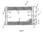
- It comprises a bundle 30 of fluid circulation tubes 20 and spacers 21, located between the tubes 20. It further comprises collectors 22 in which the tubes 20 open at their ends 20a.
- the collectors 20 are here provided with flange 23, 24 input / output.
- the bottle 1 is located parallel to one of the manifolds 22.
- the condenser allows a flow of fluid between the bottle 1 and the collector 22 neighbor, for example via the inlet / outlet ports 4, 5 of said bottle 1 so that the condenser here has a subcooling pass.
- the partition wall 8 of the bottle 1 is sealed. It is configured to stay watertight during soldering. It is further configured to be punctured after brazing, for example under the effect of a pressure tightness test of said condenser. In this way, it enables the first and second housings 2, 3 of said bottle 1 to communicate with one another.
Landscapes
- Engineering & Computer Science (AREA)
- General Engineering & Computer Science (AREA)
- Mechanical Engineering (AREA)
- Thermal Sciences (AREA)
- Physics & Mathematics (AREA)
- Chemical & Material Sciences (AREA)
- Power Engineering (AREA)
- Analytical Chemistry (AREA)
- Life Sciences & Earth Sciences (AREA)
- Sustainable Development (AREA)
- Combustion & Propulsion (AREA)
- Air-Conditioning For Vehicles (AREA)
- Heat-Exchange Devices With Radiators And Conduit Assemblies (AREA)
- Details Of Heat-Exchange And Heat-Transfer (AREA)
Description
- La présente invention concerne une bouteille réservoir de fluide réfrigérant et un échangeur de chaleur, notamment condenseur, comprenant une telle bouteille.
- L'invention trouve une application particulièrement avantageuse dans le domaine de la climatisation des véhicules automobiles. Le document
EP1386653 divulgue une bouteille réservoir de fluide réfrigérant selon le préambule de la revendication 1. - D'une manière générale, les circuits de climatisation doivent répondre à un certain nombre de critères stricts concernant les conditions d'ambiance dans lesquelles circule le fluide réfrigérant, tel que le fluide connu sous l'appellation R134A.
- En effet, il faut éviter la présence dans le circuit de corps étrangers trop nombreux ou d'une taille trop importante, car ils peuvent générer des problèmes pouvant mener jusqu'à la casse de certains composants des circuits de climatisation, comme le compresseur.
- D'autre part, le fluide réfrigérant doit pouvoir circuler dans une ambiance exempte d'humidité, car les molécules d'eau ont tendance à produire des composés acides en présence de R134A et d'huile. Ces composés attaquent alors les composants du circuit, ce qui peut occasionner des fuites et la perte de fonctionnalités.
- Il est connu d'équiper les circuits de climatisation de bouteilles contenant une certaine quantité de fluide réfrigérant en phase liquide. Ces bouteilles servent, d'une part, de réservoirs de fluide destinés à compenser d'éventuelles fuites dans les circuits, et, d'autre part, à garantir, qu'en sortie des bouteilles, le fluide réfrigérant est totalement en phase liquide avant d'être acheminé en aval. Dans des réalisations particulières, la sortie de la bouteille est ramenée dans une section du condenseur de manière à faire subir au fluide réfrigérant liquide un passage supplémentaire, dit de sous-refroidissement.
- Il est aussi connu de tirer profit de la présence de bouteilles réservoirs sur le trajet suivi par le fluide réfrigérant pour résoudre les problèmes d'ambiance évoqués plus haut. A cet effet, un filtre et un dessiccateur sont disposés à l'intérieur des bouteilles afin d'éliminer au maximum la présence de corps étrangers et d'humidité dans les boucles de circulation du fluide réfrigérant.
- Il existe deux grandes familles de bouteilles, à savoir les bouteilles dites rapportées et les bouteilles dites intégrées.
- Les bouteilles rapportées sont fournies déjà équipées d'un filtre et d'un dessiccateur. Elles sont assemblées au condenseur en finition, au moyen de vis et de joints toriques. Cependant, si ce type de bouteilles présente l'avantage d'être démontable, il n'en exige pas moins une opération spécifique d'assemblage, coûteuse.
- Les bouteilles intégrées sont pré assemblés au condenseur et subissent le processus de brasage servant à l'assemblage de ce dernier.
- En cas de présence du dessiccateur dans la bouteille lors du brasage, celui subirait un dégazage qui pose problème. On prévoit ainsi sur les bouteilles intégrées une ouverture à travers laquelle le filtre et le dessiccateur peuvent être introduits dans les bouteilles en finition, l'ouverture étant fermée par un bouchon amovible. Il est d'ailleurs possible avec cette solution de changer à volonté le filtre et le dessiccateur sans changer l'ensemble du condenseur.
- Afin de réduire les coûts de fabrication et les risques de fuites inhérents au système d'étanchéité par joints toriques des bouchons amovibles, il y a avantage à utiliser des systèmes de bouteilles intégrées scellées.
- On connaît de tels systèmes de bouteilles intégrées scellées dans lesquels l'ouverture prévue pour l'introduction du filtre et du dessiccateur est fermée par une capsule scellée par soudure au tungstène sous gaz inerte (soudure dite TIG) ou par soudure laser.
- Toutefois, cette solution n'est pas très intéressante en termes de coût, car la soudure TIG ou laser en finition est relativement lourde.
- C'est pourquoi on a envisagé des bouteilles, pré équipées d'un filtre et d'un dessiccateur, scellées et brasées en une seule opération avec le condenseur lors du brasage de ce dernier. Cette solution est susceptible d'être très économique car il n'y a pas d'autres opérations supplémentaires à implémenter sur le condenseur en sortie du four de brasage.
- Il subsiste cependant une difficulté avec ce type de solution qui réside dans le comportement du dessiccateur au cours du processus de brasage. Plus précisément, à haute température, celui-ci a tendance à diffuser, vers le condenseur avec lequel il communique, de l'humidité qui pollue l'atmosphère neutre du four et perturbe l'opération de brasage. Il en résulte des fuites dans les condenseurs fabriqués qui interdisent l'industrialisation de cette solution.
- Une solution a été proposée qui consiste à confiner le dessiccateur dans une partie de la bouteille par le biais d'un filtre métallique, enduit de polyuréthane. Cela permet de maintenir la pollution due au dégazage du dessiccateur pendant le processus de brasage du condenseur. Une fois le brasage effectué, le polyuréthane disparaît permettant la circulation du R134A au contact du dessiccateur. Les paramètres permettant de maîtriser la disparition du polyuréthane sont cependant complexes.
- La présente invention vise à améliorer la situation et propose à cet effet une bouteille réservoir de fluide réfrigérant, destinée à équiper un échangeur de chaleur d'un circuit de climatisation, ladite bouteille définissant un premier logement accueillant un dessiccateur et un second logement, apte à autoriser une communication de fluide avec ledit circuit, ladite bouteille étant configurée pour que lesdits premier et second logements restent isolés l'un de l'autre jusqu'à un premier seuil de pression interne et soient mis en communication de fluide une fois ledit second logement soumis à un second seuil de pression interne, supérieur au premier seuil.
- Ainsi, on comprend que, lors du processus de brasage dans lequel la bouteille est destinée à être impliquée, le dessiccateur restera confiné à l'intérieur de la bouteille, empêchant de cette manière toute pollution de l'atmosphère de brasage par l'humidité susceptible de s'échapper du fait du dégazage du dessiccateur. Par contre, à l'issue de l'opération de brasage, le confinement du dessiccateur pourra être levé, permettant de la sorte l'action dessiccative de ce dernier.
- On dispose ainsi d'une solution dans laquelle le dessiccateur reste isolé pendant le brasage et dans laquelle, après brasage, la bouteille permet la circulation du fluide au contact du dessiccateur. Le choix de la pression comme paramètre permettant de passer d'un mode à l'autre autorise en outre un contrôle simplifié des opérations.
- Selon différents modes de réalisation, qui pourront être pris ensemble ou séparément :
- ladite bouteille est métallique, notamment en aluminium ou alliages d'aluminium,
- la bouteille comprend une paroi de séparation, isolant lesdits premier et second logements l'un de l'autre, ladite paroi de séparation étant prévue fusible sous pression,
- la bouteille comprend des parois, dite latérales, séparant lesdits premier et second logements de l'extérieur, et la paroi de séparation est issue de matière de l'une et/ou l'autre desdites parois latérales,
- ladite paroi de séparation présente une épaisseur comprise entre 0.07 et 0.7 mm, notamment entre 0,2 et 0,5 mm,
- ladite bouteille comprend un premier corps tubulaire définissant ledit premier logement et un second corps définissant ledit second logement, ledit premier corps tubulaire présentant une extrémité ouverte fermée par ledit second corps de sorte que ledit second corps définisse ladite paroi de séparation,
- le second corps présente une forme tubulaire ouverte à l'une de ses extrémités,
- la bouteille comprend un bouchon de fermeture du second corps, brasé audit second corps,
- le second corps présente une première épaisseur au niveau de la paroi de séparation et une épaisseur supérieure au niveau de la paroi latérale de la bouteille,
- les premier et second corps sont de section sensiblement circulaire et présente un diamètre sensiblement identique,
- ledit premier corps et/ou ledit second corps sont formés par impact extrusion,
- ladite bouteille comprend un cordon de soudure entre ledit premier corps et ledit second corps.
- L'invention concerne également un échangeur de chaleur, notamment condenseur, comprenant une bouteille telle que décrite plus haut. Dans ledit échangeur, ladite paroi de séparation pourra être crevée, en particulier après avoir soumis l'échangeur à un test d'étanchéité.
- La description qui va suivre en regard des dessins annexés, donnés à titre d'exemples non limitatifs, fera bien comprendre en quoi consiste l'invention et comment elle peut être réalisée.
- La
figure 1 est une vue en perspective éclatée d'une exemple de bouteille conforme à l'invention. - La
figure 2 est une vue en perspective, selon un plan de coupe diamétrale, de la bouteille de lafigure 1 , illustrée de façon assemblée. - La
figure 3 est une vue illustrant la paroi de séparation de la bouteille des figures précédentes, une fois crevée. - La
figure 4 est une vue schématique illustrant de face un exemple de condenseur conforme à l'invention. - Comme illustré aux
figures 1 et 2 , l'invention concerne une bouteille réservoir 1 de fluide réfrigérant, destinée à équiper un échangeur de chaleur d'un circuit de climatisation, notamment un condenseur. - Ladite bouteille 1 définit un premier logement 2 accueillant un dessiccateur, non représenté, et un second logement 3, apte à autoriser une communication de fluide avec ledit circuit de climatisation, notamment par l'intermédiaire de deux orifices 4, 5 d'entrée/sortie. Lesdits logements 2, 3 sont dans le prolongement l'un de l'autre selon l'axe longitudinale de la bouteille.
- Selon l'invention, ladite bouteille 1 est configurée pour que lesdits premier 2 et second 3 logements restent isolés l'un de l'autre jusqu'à un premier seuil de pression interne et soient mis en communication de fluide une fois ledit second logement 3 soumis à un second seuil de pression interne, supérieur au premier seuil.
- Ledit premier seuil de pression interne correspond, par exemple, à une pression supérieure à la pression différentielle susceptible d'être rencontrée entre ledit premier logement 2, prévu soumis à des phénomènes de diffusion du dessiccateur sous l'effet de la chaleur dégagée par une opération de brasage dans laquelle la bouteille est impliquée, et ledit second logement 3, prévu soumis à l'atmosphère de brasage.
- Ledit second seuil de pression interne correspond, par exemple, à une pression de test d'étanchéité telle que la pression utilisée pour les tests d'étanchéité à l'hélium pratiqués sur les condenseurs.
- Pendant le brasage, le dessiccateur reste ainsi confiné dans le premier logement 2. Après le test d'étanchéité, il est par contre dans le circuit de fluide, ce dernier pouvant passer dudit second logement 3 audit premier logement 2.
- Ladite bouteille 1 comprend, notamment, des parois 6, 7, dite latérales, séparant lesdits premier 1 et second 2 logements de l'extérieur et une paroi de séparation 8, isolant ledit premier 1 et ledit second 2 logement l'un de l'autre. Ladite paroi de séparation 8 est prévu fusible sous pression, comme cela sera développé en relation avec la
figure 3 . - Ladite paroi de séparation est, par exemple, issue de matière de l'une 6 et/ou l'autre 7 desdites parois latérales. On dispose ainsi d'une bouteille particulièrement simple, sans pièce rapportée pour définir la solution permettant d'isoler le dessiccateur pendant le brasage.
- Ladite paroi de séparation 8 présente, par exemple, une épaisseur comprise entre 0.07 et 0.7 mm, notamment entre 0,2 et 0,5 mm.
- A ce sujet, ladite bouteille pourra être métallique, par exemple en aluminium ou alliages d'aluminium.
- Ladite bouteille 1 comprend, notamment, un premier corps tubulaire 9 définissant ledit premier logement 2 et un second corps 10 définissant ledit second logement 3. Ledit premier corps tubulaire 9 présente une extrémité ouverte 11, fermée par ledit second corps 10 de sorte que ledit second corps 10 définisse ladite paroi de séparation 8.
- Le second corps 10 pourra présenter lui aussi une forme tubulaire, ouverte à l'une 12 de ses extrémités. La bouteille 1 pourra d'ailleurs comprendre un bouchon 13 de fermeture du second corps 10, brasé audit second corps 10, au niveau de ladite extrémité ouverte 12 de ce dernier.
- Ledit second corps 10 présente lesdits orifices d'entrée/sortie 4, 5 pour le fluide. Ils sont ici situés sur sa paroi latérale 7. Un filtre, non représenté, pourra être situé dans ledit second corps 10 entre lesdits orifices 4, 5.
- Le second corps 10 pourra présenter au moins deux épaisseurs disctinctes ; une première épaisseur telle que celle évoquée plus haut au niveau de la paroi de séparation 8 et une épaisseur supérieure au niveau de sa paroi latérale 7. Il pourra s'agir d'une épaisseur de 1 à 2 mm, notamment 1,5 mm, l'épaisseur de la paroi de séparation 8 étant alors, par exemple, de 0,4 mm.
- Les premier 9 et second 10 corps sont ici de section sensiblement circulaire et présente un diamètre sensiblement identique. Ils sont formés, par exemple, par impact extrusion. Ils pourront être reliés par un cordon de soudure 14, obtenue par soudure TIG, MIG, laser ou autre procédé de soudure.
- Comme illustré à la
figure 3 , ladite paroi de séparation 8, après avoir été soumise à une pression dépassant le second seuil de pression, est crevée. On distingue à cette figure l'arrachement de matière permettant la création d'un orifice de passage 15 dans ladite paroi de séparation 8, permettant la mise en communication du premier logement 2 et du second logement 3. On comprend ainsi qu'avant application dudit second seuil de pression, le premier logement 2 est isolé et protège d'une diffusion provenant du dessiccateur tandis que, après application dudit second seuil de pression ou d'une pression supérieure, ledit premier logement 2 est relié au second logement 3 par la création dudit orifice de passage 15 entre lesdits logements 2,3. - Comme illustré à la
figure 4 , l'invention concerne également un échangeur de chaleur, notamment condenseur, muni d'une bouteille 1 telle que décrite plus haut. - Il comprend un faisceau 30 de tubes 20 de circulation du fluide et d'intercalaires 21, situés entre les tubes 20. Il comprend en outre des collecteurs 22 dans lesquels les tubes 20 débouchent par leurs extrémités 20a. Les collecteurs 20 sont ici munis de bride 23, 24 d'entrée/sortie.
- La bouteille 1 est située parallèlement à l'un des collecteurs 22. Le condenseur permet une circulation de fluide entre la bouteille 1 et le collecteur 22 voisin, par exemple par l'intermédiaire des orifices d'entrée / sortie 4, 5 de ladite bouteille 1 de sorte que le condenseur présente ici une passe de sous-refroidissement.
- Dans le condenseur pré assemblé avant brasage, la paroi de séparation 8 de la bouteille 1 est étanche. Elle est configurée pour rester étanche pendant le brasage. Elle est en outre configurée pour être crevée après brasage, par exemple sous l'effet d'un test d'étanchéité sous pression dudit condenseur. Elle permet de la sorte la mise en communication des premier et second logements 2, 3 de ladite bouteille 1.
Claims (12)
- Bouteille réservoir de fluide réfrigérant, destinée à équiper un échangeur de chaleur d'un circuit de climatisation, ladite bouteille définissant un premier logement (2) accueillant un dessiccateur et un second logement (3), apte à autoriser une communication de fluide avec ledit circuit, caractérisée par la bouteille étant configurée pour que lesdits premier (2) et second (3) logements restent isolés l'un de l'autre jusqu'à un premier seuil de pression interne et soient mis en communication de fluide une fois ledit second logement (3) soumis à un second seuil de pression interne, supérieur au premier seuil.
- Bouteille selon la revendication 1 comprenant une paroi de séparation (8), isolant lesdits premier (2) et second (3) logements l'un de l'autre, ladite paroi de séparation (8) étant prévue fusible sous pression.
- Bouteille selon la revendication 2 comprenant des parois (6, 7), dite latérales, séparant lesdits premier (2) et second (3) logements de l'extérieur, et dans laquelle ladite paroi de séparation (8) est issue de matière de l'une et/ou l'autre desdites parois latérales (6, 7).
- Bouteille selon la revendication 3 comprenant un premier corps tubulaire (9) définissant ledit premier logement (2) et un second corps (10) définissant ledit second logement (3), ledit premier corps tubulaire (9) présentant une extrémité ouverte (11) fermée par ledit second corps (10) de sorte que ledit second corps (10) définisse ladite paroi de séparation (8).
- Bouteille selon la revendication 4 dans lequel le second corps (10) présente une forme tubulaire ouverte à l'une de ses extrémités (12).
- Bouteille selon l'une quelconque des revendications 4 ou 5 comprenant un bouchon (13) de fermeture du second corps (10), brasé audit second corps (10).
- Bouteille selon l'une quelconque des revendications 4 à 6 dans lequel le second corps (10) présente une première épaisseur au niveau de la paroi de séparation (8) et une épaisseur supérieure au niveau de la paroi latérale (7) de la bouteille (1).
- Bouteille selon l'une quelconque des revendications 4 à 7 dans laquelle ledit premier corps (9) et/ou ledit second corps (10) sont formés par impact extrusion.
- Bouteille selon l'une quelconque des revendications 4 à 8 comprenant un cordon de soudure (14) entre ledit premier corps (9) et ledit second corps (10).
- Bouteille selon l'une quelconque des revendications 2 à 9 dans laquelle ladite paroi de séparation (8) présente une épaisseur comprise entre 0.07 et 0.7 mm, notamment entre 0,2 et 0,5 mm.
- Echangeur de chaleur comprenant une bouteille (1) selon l'une quelconque des revendications précédentes.
- Echangeur selon la revendication 11, prise dans son rattachement à l'une quelconque des revendications 2 à 10, dans lequel ladite paroi de séparation (8) est crevée.
Priority Applications (1)
| Application Number | Priority Date | Filing Date | Title |
|---|---|---|---|
| PL12738137T PL2737267T3 (pl) | 2011-07-25 | 2012-07-24 | Butla stanowiąca zbiornik czynnika chłodzącego i wymiennik ciepła zawierający taką butlę |
Applications Claiming Priority (2)
| Application Number | Priority Date | Filing Date | Title |
|---|---|---|---|
| FR1156754A FR2978536B1 (fr) | 2011-07-25 | 2011-07-25 | Bouteille reservoir de fluide refrigerant et echangeur de chaleur comprenant une telle bouteille |
| PCT/EP2012/064496 WO2013014152A1 (fr) | 2011-07-25 | 2012-07-24 | Bouteille reservoir de fluide refrigerant et echangeur de chaleur comprenant une telle bouteille |
Publications (2)
| Publication Number | Publication Date |
|---|---|
| EP2737267A1 EP2737267A1 (fr) | 2014-06-04 |
| EP2737267B1 true EP2737267B1 (fr) | 2015-09-09 |
Family
ID=46551570
Family Applications (1)
| Application Number | Title | Priority Date | Filing Date |
|---|---|---|---|
| EP12738137.4A Not-in-force EP2737267B1 (fr) | 2011-07-25 | 2012-07-24 | Bouteille reservoir de fluide refrigerant et echangeur de chaleur comprenant une telle bouteille |
Country Status (7)
| Country | Link |
|---|---|
| US (1) | US10126006B2 (fr) |
| EP (1) | EP2737267B1 (fr) |
| JP (1) | JP6100256B2 (fr) |
| CN (1) | CN103827603B (fr) |
| FR (1) | FR2978536B1 (fr) |
| PL (1) | PL2737267T3 (fr) |
| WO (1) | WO2013014152A1 (fr) |
Families Citing this family (7)
| Publication number | Priority date | Publication date | Assignee | Title |
|---|---|---|---|---|
| CN103928939B (zh) * | 2014-04-14 | 2016-01-20 | 国家电网公司 | 直流换相失败冲击下交流联络线功率波动峰值的计算方法 |
| USD756781S1 (en) * | 2014-09-17 | 2016-05-24 | Quad/Graphics, Inc. | Display panel for a sampler |
| USD756780S1 (en) | 2014-09-17 | 2016-05-24 | Quad/Graphics, Inc. | Display panel for a sampler |
| JP6572931B2 (ja) * | 2016-04-08 | 2019-09-11 | 株式会社デンソー | 熱交換器 |
| EP4122359B1 (fr) | 2021-07-19 | 2025-12-24 | De Rigo Refrigeration S.r.l. | Système de réfrigérateur |
| US20240366701A1 (en) | 2021-09-03 | 2024-11-07 | Lubrizol Advanced Materials, Inc. | Extract of myrothamnus sp for promoting hair growth |
| FR3167432A1 (fr) * | 2024-10-11 | 2026-04-17 | Valeo Systemes Thermiques | Bouteille déshydratante |
Citations (19)
| Publication number | Priority date | Publication date | Assignee | Title |
|---|---|---|---|---|
| DE2513671C3 (de) | 1975-03-27 | 1979-06-07 | Brown Boveri - York Kaelte- Und Klimatechnik Gmbh, 6800 Mannheim | Kälteanlage mit einem Kältemittel-Sammelbehälter |
| DE4337349A1 (de) | 1992-11-02 | 1994-05-11 | Nippon Denso Co | Kühlmittelkondensator |
| DE19915648A1 (de) | 1999-04-07 | 2000-10-12 | Rohde & Schwarz | Verfahren zum Bewerten der Sprachqualität von Telefonverbindungen |
| DE4238853C2 (de) | 1992-11-18 | 2001-05-03 | Behr Gmbh & Co | Kondensator für eine Klimaanlage eines Fahrzeuges |
| EP1291592A1 (fr) | 2001-09-07 | 2003-03-12 | DENSO THERMAL SYSTEMS S.p.A. | Condenseur pour systèmes de conditionnement d'air de véhicules |
| EP1310760A1 (fr) | 2001-11-08 | 2003-05-14 | Behr GmbH & Co. | Condenseur de fluide frigoporteur |
| DE10213194A1 (de) | 2002-03-25 | 2003-10-16 | Behr Gmbh & Co | Gelöteter Kältemittelkondensator |
| EP1386653A1 (fr) | 2002-07-31 | 2004-02-04 | Behr GmbH & Co. | Filtre et échangeur de chaleur ou système de circuit frigorifique avec un tel filtre |
| US6694773B1 (en) | 2003-01-29 | 2004-02-24 | Calsonickansei North America, Inc. | Condenser system with nondetachably coupled receiver |
| DE10338526A1 (de) | 2002-08-31 | 2004-03-11 | Behr Gmbh & Co. Kg | Sammler für ein Kältemittel, Wärmetauscher, Kältemittelkreislauf und Verfahren zur Herstellung eines Sammlers |
| US20040123735A1 (en) | 2002-12-26 | 2004-07-01 | Tadaharu Watanabe | Method and system for supplying high purity fluid |
| DE102004038789A1 (de) | 2004-08-09 | 2006-02-23 | Behr Gmbh & Co. Kg | Berstscheibenanordnung |
| DE102005004519A1 (de) | 2005-01-31 | 2006-08-10 | Behr Gmbh & Co. Kg | Kondensator für eine Klimaanlage, insbesondere eines Kraftfahrzeuges |
| DE102005017918A1 (de) | 2005-04-18 | 2006-10-19 | Behr Gmbh & Co. Kg | Überdrucksicherheitseinrichtung für einen Kältemittelkreislauf |
| EP1519849B1 (fr) | 2002-06-27 | 2007-02-28 | Luk Fahrzeug-Hydraulik GmbH & Co. KG | Installation de climatisation dotee d'un equipement a plaque de rupture |
| DE102006017071A1 (de) | 2006-04-10 | 2007-10-11 | Behr Gmbh & Co. Kg | Akkumulator mit innerem Wärmetauscher, insbesondere für eine Kraftfahrzeug-Klimaanlage |
| DE102005024167B4 (de) | 2005-05-23 | 2008-05-15 | Jahn Gmbh Umform- Und Zerspanungstechnik | Trockner für ein Kühlmedium in einem Kühlmedienkreislauf, insbesondere für eine Klimaanlage eines Fahrzeugs |
| DE102007051512A1 (de) | 2007-10-29 | 2009-04-30 | Jahn Gmbh Umform- Und Zerspanungstechnik | Trockner für ein Kältemittel in einem Kältemittelkreislauf, insbesondere für eine Klimaanlage eines Fahrzeugs, und zugehörige Kältemittelkondensatoranordnung |
| DE102009028276A1 (de) | 2009-08-06 | 2011-02-10 | Robert Bosch Gmbh | Schutzvorrichtung für eine Testanlage |
Family Cites Families (15)
| Publication number | Priority date | Publication date | Assignee | Title |
|---|---|---|---|---|
| US5787563A (en) * | 1996-05-07 | 1998-08-04 | Mst Automotive Of America Inc. | Method for assembling a compressed air bag inflator |
| JP2000039232A (ja) * | 1998-07-23 | 2000-02-08 | Sanden Corp | 受液器組込凝縮器 |
| JP2001141332A (ja) * | 1999-11-12 | 2001-05-25 | Denso Corp | 受液器の製造方法 |
| CN1678874A (zh) * | 2002-08-31 | 2005-10-05 | 贝洱两合公司 | 适用于汽车空调的冷却剂冷凝器 |
| ATE426784T1 (de) * | 2003-11-14 | 2009-04-15 | Behr Gmbh & Co Kg | Warmetauscher |
| US6981389B2 (en) * | 2003-12-12 | 2006-01-03 | Calsonickansei North America, Inc. | Receiver and service cartridge for a condenser system |
| JP2006052938A (ja) * | 2004-07-15 | 2006-02-23 | Showa Denko Kk | 冷凍サイクル用レシーバドライヤおよび一体型熱交換器 |
| JP2006038309A (ja) * | 2004-07-26 | 2006-02-09 | Tgk Co Ltd | 冷媒リリーフ装置 |
| US7073571B2 (en) * | 2004-09-23 | 2006-07-11 | Visteon Global Technologies, Inc. | Integrated condenser oil cooler with a receiver/dryer |
| JP2006162189A (ja) * | 2004-12-09 | 2006-06-22 | Nikkei Nekko Kk | 熱交換器用レシーバタンク |
| US20060123837A1 (en) * | 2004-12-10 | 2006-06-15 | Subros Limited | Receiver tank for a condensor and method of manufacturing the same |
| DE102005021787A1 (de) * | 2005-05-11 | 2006-11-16 | Modine Manufacturing Co., Racine | Vorrichtung zur Behandlung des Kältemittels |
| TW200722692A (en) * | 2005-07-20 | 2007-06-16 | Fujikoki Corp | Receiver drier and condenser integrated with receiver dryer |
| ITMI20070701A1 (it) * | 2007-04-04 | 2008-10-05 | Ti Automotive Cisliano S R L | Serbatoio del refrigerante integrabile ad un condensatore di un impianto di refrigerazione automobilistico |
| CN101482378B (zh) * | 2008-12-29 | 2011-08-10 | 清华大学 | 一种分段式汽液相变换热器的汽液分离方法及换热器 |
-
2011
- 2011-07-25 FR FR1156754A patent/FR2978536B1/fr not_active Expired - Fee Related
-
2012
- 2012-07-24 WO PCT/EP2012/064496 patent/WO2013014152A1/fr not_active Ceased
- 2012-07-24 JP JP2014522059A patent/JP6100256B2/ja not_active Expired - Fee Related
- 2012-07-24 PL PL12738137T patent/PL2737267T3/pl unknown
- 2012-07-24 US US14/234,682 patent/US10126006B2/en active Active
- 2012-07-24 EP EP12738137.4A patent/EP2737267B1/fr not_active Not-in-force
- 2012-07-24 CN CN201280046602.XA patent/CN103827603B/zh active Active
Patent Citations (19)
| Publication number | Priority date | Publication date | Assignee | Title |
|---|---|---|---|---|
| DE2513671C3 (de) | 1975-03-27 | 1979-06-07 | Brown Boveri - York Kaelte- Und Klimatechnik Gmbh, 6800 Mannheim | Kälteanlage mit einem Kältemittel-Sammelbehälter |
| DE4337349A1 (de) | 1992-11-02 | 1994-05-11 | Nippon Denso Co | Kühlmittelkondensator |
| DE4238853C2 (de) | 1992-11-18 | 2001-05-03 | Behr Gmbh & Co | Kondensator für eine Klimaanlage eines Fahrzeuges |
| DE19915648A1 (de) | 1999-04-07 | 2000-10-12 | Rohde & Schwarz | Verfahren zum Bewerten der Sprachqualität von Telefonverbindungen |
| EP1291592A1 (fr) | 2001-09-07 | 2003-03-12 | DENSO THERMAL SYSTEMS S.p.A. | Condenseur pour systèmes de conditionnement d'air de véhicules |
| EP1310760A1 (fr) | 2001-11-08 | 2003-05-14 | Behr GmbH & Co. | Condenseur de fluide frigoporteur |
| DE10213194A1 (de) | 2002-03-25 | 2003-10-16 | Behr Gmbh & Co | Gelöteter Kältemittelkondensator |
| EP1519849B1 (fr) | 2002-06-27 | 2007-02-28 | Luk Fahrzeug-Hydraulik GmbH & Co. KG | Installation de climatisation dotee d'un equipement a plaque de rupture |
| EP1386653A1 (fr) | 2002-07-31 | 2004-02-04 | Behr GmbH & Co. | Filtre et échangeur de chaleur ou système de circuit frigorifique avec un tel filtre |
| DE10338526A1 (de) | 2002-08-31 | 2004-03-11 | Behr Gmbh & Co. Kg | Sammler für ein Kältemittel, Wärmetauscher, Kältemittelkreislauf und Verfahren zur Herstellung eines Sammlers |
| US20040123735A1 (en) | 2002-12-26 | 2004-07-01 | Tadaharu Watanabe | Method and system for supplying high purity fluid |
| US6694773B1 (en) | 2003-01-29 | 2004-02-24 | Calsonickansei North America, Inc. | Condenser system with nondetachably coupled receiver |
| DE102004038789A1 (de) | 2004-08-09 | 2006-02-23 | Behr Gmbh & Co. Kg | Berstscheibenanordnung |
| DE102005004519A1 (de) | 2005-01-31 | 2006-08-10 | Behr Gmbh & Co. Kg | Kondensator für eine Klimaanlage, insbesondere eines Kraftfahrzeuges |
| DE102005017918A1 (de) | 2005-04-18 | 2006-10-19 | Behr Gmbh & Co. Kg | Überdrucksicherheitseinrichtung für einen Kältemittelkreislauf |
| DE102005024167B4 (de) | 2005-05-23 | 2008-05-15 | Jahn Gmbh Umform- Und Zerspanungstechnik | Trockner für ein Kühlmedium in einem Kühlmedienkreislauf, insbesondere für eine Klimaanlage eines Fahrzeugs |
| DE102006017071A1 (de) | 2006-04-10 | 2007-10-11 | Behr Gmbh & Co. Kg | Akkumulator mit innerem Wärmetauscher, insbesondere für eine Kraftfahrzeug-Klimaanlage |
| DE102007051512A1 (de) | 2007-10-29 | 2009-04-30 | Jahn Gmbh Umform- Und Zerspanungstechnik | Trockner für ein Kältemittel in einem Kältemittelkreislauf, insbesondere für eine Klimaanlage eines Fahrzeugs, und zugehörige Kältemittelkondensatoranordnung |
| DE102009028276A1 (de) | 2009-08-06 | 2011-02-10 | Robert Bosch Gmbh | Schutzvorrichtung für eine Testanlage |
Also Published As
| Publication number | Publication date |
|---|---|
| JP6100256B2 (ja) | 2017-03-22 |
| JP2014521912A (ja) | 2014-08-28 |
| WO2013014152A1 (fr) | 2013-01-31 |
| CN103827603A (zh) | 2014-05-28 |
| US10126006B2 (en) | 2018-11-13 |
| FR2978536A1 (fr) | 2013-02-01 |
| FR2978536B1 (fr) | 2013-08-23 |
| US20140231279A1 (en) | 2014-08-21 |
| EP2737267A1 (fr) | 2014-06-04 |
| CN103827603B (zh) | 2016-01-20 |
| PL2737267T3 (pl) | 2016-06-30 |
Similar Documents
| Publication | Publication Date | Title |
|---|---|---|
| WO2013014152A1 (fr) | Bouteille reservoir de fluide refrigerant et echangeur de chaleur comprenant une telle bouteille | |
| EP2137477B1 (fr) | Échangeur de chaleur pour gaz | |
| FR2947041A1 (fr) | Condenseur avec reserve de fluide frigorigene pour circuit de climatisation | |
| FR2676535A1 (fr) | Echangeur de chaleur muni d'une boite a fluide tubulaire a cloisons transversales, et procede pour sa realisation. | |
| FR2947331A1 (fr) | Echangeur de chaleur comprenant un faisceau de tubes avec au moins un tube inactif | |
| EP2164728B1 (fr) | Procede de fabrication d'un reservoir pour le liquide de lavage des surfaces vitrees d'un vehicule automobile et reservoir obtenu par ce procede | |
| WO2014064086A2 (fr) | Échangeur thermique, notamment pour vehicule automobile | |
| FR2712039A1 (fr) | Moteur oscillant hydraulique. | |
| FR3062714A1 (fr) | Circuit de gestion thermique et echangeur thermique associe | |
| FR2785552A1 (fr) | Dispositif de filtration pour circuit frigorifique et procede de filtration utilisant un tel dispositif | |
| EP3390956B1 (fr) | Generateur de gaz | |
| EP2434235B1 (fr) | Ensemble d'un échangeur de chaleur biphasique et d'une bouteille | |
| EP2516093B1 (fr) | Procédé de brasage d'un composant de circuit de climatisation comportant une bouteille réservoir de fluide réfrigerant et une telle bouteille | |
| FR2777638A1 (fr) | Condenseur a reservoir integre pour bloc de traitement de fluide amovible, notamment pour un circuit de climatisation de vehicule automobile | |
| FR2661489A1 (fr) | Dispositif de boite a eau et de vase d'expansion pour un echangeur de chaleur, tel qu'un radiateur de refroidissement, et echangeur de chaleur comprenant ce dispositif. | |
| EP0710145B1 (fr) | Dispositif de filtration pour circuit frigorifique et procede de fabrication d'un tel dispositif | |
| FR3092281A1 (fr) | Agencement d’un compartiment moteur d’un véhicule automobile | |
| FR2825456A1 (fr) | Echangeur de chaleur a boitier allonge, en particulier pour vehicule automobile | |
| EP0446099B1 (fr) | Raccord à quatre voies de forme compacte et son utilisation sur le circuit de refroidissement d'un véhicule automobile | |
| EP3695492B1 (fr) | Machine électrique et procédé de fabrication | |
| WO2002077548A1 (fr) | Condenseur de climatisation, notamment pour un vehicule automobile, comportant une embase raccordee a une boite collectrice | |
| EP3042709B1 (fr) | Filtre à liquide présentant une étanchéité améliorée | |
| FR2924193A1 (fr) | Raccord etanche et procede de montage d'un tel reccord | |
| FR2910120A1 (fr) | Boite a eau pour echangeur de chaleur et echangeur de chaleur comportant une telle boite a eau | |
| FR2916829A1 (fr) | Raccord entre une tubulure d'admission ou de collecte de fluide caloporteur et un embout d'entree ou de sortie de fluide d'un echangeur de chaleur |
Legal Events
| Date | Code | Title | Description |
|---|---|---|---|
| PUAI | Public reference made under article 153(3) epc to a published international application that has entered the european phase |
Free format text: ORIGINAL CODE: 0009012 |
|
| 17P | Request for examination filed |
Effective date: 20140122 |
|
| AK | Designated contracting states |
Kind code of ref document: A1 Designated state(s): AL AT BE BG CH CY CZ DE DK EE ES FI FR GB GR HR HU IE IS IT LI LT LU LV MC MK MT NL NO PL PT RO RS SE SI SK SM TR |
|
| DAX | Request for extension of the european patent (deleted) | ||
| GRAP | Despatch of communication of intention to grant a patent |
Free format text: ORIGINAL CODE: EPIDOSNIGR1 |
|
| INTG | Intention to grant announced |
Effective date: 20150327 |
|
| GRAS | Grant fee paid |
Free format text: ORIGINAL CODE: EPIDOSNIGR3 |
|
| GRAA | (expected) grant |
Free format text: ORIGINAL CODE: 0009210 |
|
| AK | Designated contracting states |
Kind code of ref document: B1 Designated state(s): AL AT BE BG CH CY CZ DE DK EE ES FI FR GB GR HR HU IE IS IT LI LT LU LV MC MK MT NL NO PL PT RO RS SE SI SK SM TR |
|
| REG | Reference to a national code |
Ref country code: GB Ref legal event code: FG4D Free format text: NOT ENGLISH |
|
| REG | Reference to a national code |
Ref country code: AT Ref legal event code: REF Ref document number: 748467 Country of ref document: AT Kind code of ref document: T Effective date: 20150915 Ref country code: CH Ref legal event code: EP |
|
| REG | Reference to a national code |
Ref country code: IE Ref legal event code: FG4D Free format text: LANGUAGE OF EP DOCUMENT: FRENCH |
|
| REG | Reference to a national code |
Ref country code: DE Ref legal event code: R096 Ref document number: 602012010424 Country of ref document: DE |
|
| REG | Reference to a national code |
Ref country code: NL Ref legal event code: MP Effective date: 20150909 |
|
| PG25 | Lapsed in a contracting state [announced via postgrant information from national office to epo] |
Ref country code: NO Free format text: LAPSE BECAUSE OF FAILURE TO SUBMIT A TRANSLATION OF THE DESCRIPTION OR TO PAY THE FEE WITHIN THE PRESCRIBED TIME-LIMIT Effective date: 20151209 Ref country code: GR Free format text: LAPSE BECAUSE OF FAILURE TO SUBMIT A TRANSLATION OF THE DESCRIPTION OR TO PAY THE FEE WITHIN THE PRESCRIBED TIME-LIMIT Effective date: 20151210 Ref country code: LT Free format text: LAPSE BECAUSE OF FAILURE TO SUBMIT A TRANSLATION OF THE DESCRIPTION OR TO PAY THE FEE WITHIN THE PRESCRIBED TIME-LIMIT Effective date: 20150909 Ref country code: FI Free format text: LAPSE BECAUSE OF FAILURE TO SUBMIT A TRANSLATION OF THE DESCRIPTION OR TO PAY THE FEE WITHIN THE PRESCRIBED TIME-LIMIT Effective date: 20150909 Ref country code: LV Free format text: LAPSE BECAUSE OF FAILURE TO SUBMIT A TRANSLATION OF THE DESCRIPTION OR TO PAY THE FEE WITHIN THE PRESCRIBED TIME-LIMIT Effective date: 20150909 |
|
| REG | Reference to a national code |
Ref country code: LT Ref legal event code: MG4D |
|
| REG | Reference to a national code |
Ref country code: AT Ref legal event code: MK05 Ref document number: 748467 Country of ref document: AT Kind code of ref document: T Effective date: 20150909 |
|
| PG25 | Lapsed in a contracting state [announced via postgrant information from national office to epo] |
Ref country code: SE Free format text: LAPSE BECAUSE OF FAILURE TO SUBMIT A TRANSLATION OF THE DESCRIPTION OR TO PAY THE FEE WITHIN THE PRESCRIBED TIME-LIMIT Effective date: 20150909 Ref country code: ES Free format text: LAPSE BECAUSE OF FAILURE TO SUBMIT A TRANSLATION OF THE DESCRIPTION OR TO PAY THE FEE WITHIN THE PRESCRIBED TIME-LIMIT Effective date: 20150909 Ref country code: HR Free format text: LAPSE BECAUSE OF FAILURE TO SUBMIT A TRANSLATION OF THE DESCRIPTION OR TO PAY THE FEE WITHIN THE PRESCRIBED TIME-LIMIT Effective date: 20150909 Ref country code: RS Free format text: LAPSE BECAUSE OF FAILURE TO SUBMIT A TRANSLATION OF THE DESCRIPTION OR TO PAY THE FEE WITHIN THE PRESCRIBED TIME-LIMIT Effective date: 20150909 |
|
| PG25 | Lapsed in a contracting state [announced via postgrant information from national office to epo] |
Ref country code: NL Free format text: LAPSE BECAUSE OF FAILURE TO SUBMIT A TRANSLATION OF THE DESCRIPTION OR TO PAY THE FEE WITHIN THE PRESCRIBED TIME-LIMIT Effective date: 20150909 |
|
| PG25 | Lapsed in a contracting state [announced via postgrant information from national office to epo] |
Ref country code: EE Free format text: LAPSE BECAUSE OF FAILURE TO SUBMIT A TRANSLATION OF THE DESCRIPTION OR TO PAY THE FEE WITHIN THE PRESCRIBED TIME-LIMIT Effective date: 20150909 Ref country code: IT Free format text: LAPSE BECAUSE OF FAILURE TO SUBMIT A TRANSLATION OF THE DESCRIPTION OR TO PAY THE FEE WITHIN THE PRESCRIBED TIME-LIMIT Effective date: 20150909 Ref country code: IS Free format text: LAPSE BECAUSE OF FAILURE TO SUBMIT A TRANSLATION OF THE DESCRIPTION OR TO PAY THE FEE WITHIN THE PRESCRIBED TIME-LIMIT Effective date: 20160109 Ref country code: SK Free format text: LAPSE BECAUSE OF FAILURE TO SUBMIT A TRANSLATION OF THE DESCRIPTION OR TO PAY THE FEE WITHIN THE PRESCRIBED TIME-LIMIT Effective date: 20150909 |
|
| PG25 | Lapsed in a contracting state [announced via postgrant information from national office to epo] |
Ref country code: RO Free format text: LAPSE BECAUSE OF FAILURE TO SUBMIT A TRANSLATION OF THE DESCRIPTION OR TO PAY THE FEE WITHIN THE PRESCRIBED TIME-LIMIT Effective date: 20150909 Ref country code: PT Free format text: LAPSE BECAUSE OF FAILURE TO SUBMIT A TRANSLATION OF THE DESCRIPTION OR TO PAY THE FEE WITHIN THE PRESCRIBED TIME-LIMIT Effective date: 20160111 Ref country code: AT Free format text: LAPSE BECAUSE OF FAILURE TO SUBMIT A TRANSLATION OF THE DESCRIPTION OR TO PAY THE FEE WITHIN THE PRESCRIBED TIME-LIMIT Effective date: 20150909 |
|
| REG | Reference to a national code |
Ref country code: DE Ref legal event code: R026 Ref document number: 602012010424 Country of ref document: DE |
|
| PLBI | Opposition filed |
Free format text: ORIGINAL CODE: 0009260 |
|
| PLAX | Notice of opposition and request to file observation + time limit sent |
Free format text: ORIGINAL CODE: EPIDOSNOBS2 |
|
| 26 | Opposition filed |
Opponent name: MAHLE INTERNATIONAL GMBH Effective date: 20160608 |
|
| REG | Reference to a national code |
Ref country code: FR Ref legal event code: PLFP Year of fee payment: 5 |
|
| PG25 | Lapsed in a contracting state [announced via postgrant information from national office to epo] |
Ref country code: DK Free format text: LAPSE BECAUSE OF FAILURE TO SUBMIT A TRANSLATION OF THE DESCRIPTION OR TO PAY THE FEE WITHIN THE PRESCRIBED TIME-LIMIT Effective date: 20150909 Ref country code: SI Free format text: LAPSE BECAUSE OF FAILURE TO SUBMIT A TRANSLATION OF THE DESCRIPTION OR TO PAY THE FEE WITHIN THE PRESCRIBED TIME-LIMIT Effective date: 20150909 |
|
| PG25 | Lapsed in a contracting state [announced via postgrant information from national office to epo] |
Ref country code: BE Free format text: LAPSE BECAUSE OF NON-PAYMENT OF DUE FEES Effective date: 20160731 |
|
| REG | Reference to a national code |
Ref country code: CH Ref legal event code: PL |
|
| GBPC | Gb: european patent ceased through non-payment of renewal fee |
Effective date: 20160724 |
|
| PG25 | Lapsed in a contracting state [announced via postgrant information from national office to epo] |
Ref country code: MC Free format text: LAPSE BECAUSE OF FAILURE TO SUBMIT A TRANSLATION OF THE DESCRIPTION OR TO PAY THE FEE WITHIN THE PRESCRIBED TIME-LIMIT Effective date: 20150909 |
|
| PLBB | Reply of patent proprietor to notice(s) of opposition received |
Free format text: ORIGINAL CODE: EPIDOSNOBS3 |
|
| PG25 | Lapsed in a contracting state [announced via postgrant information from national office to epo] |
Ref country code: CH Free format text: LAPSE BECAUSE OF NON-PAYMENT OF DUE FEES Effective date: 20160731 Ref country code: LI Free format text: LAPSE BECAUSE OF NON-PAYMENT OF DUE FEES Effective date: 20160731 |
|
| REG | Reference to a national code |
Ref country code: IE Ref legal event code: MM4A |
|
| PG25 | Lapsed in a contracting state [announced via postgrant information from national office to epo] |
Ref country code: GB Free format text: LAPSE BECAUSE OF NON-PAYMENT OF DUE FEES Effective date: 20160724 |
|
| PLAK | Information related to reply of patent proprietor to notice(s) of opposition modified |
Free format text: ORIGINAL CODE: EPIDOSCOBS3 |
|
| PLAS | Information related to reply of patent proprietor to notice(s) of opposition deleted |
Free format text: ORIGINAL CODE: EPIDOSDOBS3 |
|
| PLBB | Reply of patent proprietor to notice(s) of opposition received |
Free format text: ORIGINAL CODE: EPIDOSNOBS3 |
|
| PG25 | Lapsed in a contracting state [announced via postgrant information from national office to epo] |
Ref country code: IE Free format text: LAPSE BECAUSE OF NON-PAYMENT OF DUE FEES Effective date: 20160724 |
|
| REG | Reference to a national code |
Ref country code: FR Ref legal event code: PLFP Year of fee payment: 6 |
|
| PG25 | Lapsed in a contracting state [announced via postgrant information from national office to epo] |
Ref country code: LU Free format text: LAPSE BECAUSE OF NON-PAYMENT OF DUE FEES Effective date: 20160724 |
|
| PLCK | Communication despatched that opposition was rejected |
Free format text: ORIGINAL CODE: EPIDOSNREJ1 |
|
| STAA | Information on the status of an ep patent application or granted ep patent |
Free format text: STATUS: THE PATENT HAS BEEN GRANTED |
|
| APBM | Appeal reference recorded |
Free format text: ORIGINAL CODE: EPIDOSNREFNO |
|
| APBP | Date of receipt of notice of appeal recorded |
Free format text: ORIGINAL CODE: EPIDOSNNOA2O |
|
| APAH | Appeal reference modified |
Free format text: ORIGINAL CODE: EPIDOSCREFNO |
|
| PG25 | Lapsed in a contracting state [announced via postgrant information from national office to epo] |
Ref country code: SM Free format text: LAPSE BECAUSE OF FAILURE TO SUBMIT A TRANSLATION OF THE DESCRIPTION OR TO PAY THE FEE WITHIN THE PRESCRIBED TIME-LIMIT Effective date: 20150909 Ref country code: CY Free format text: LAPSE BECAUSE OF FAILURE TO SUBMIT A TRANSLATION OF THE DESCRIPTION OR TO PAY THE FEE WITHIN THE PRESCRIBED TIME-LIMIT Effective date: 20150909 Ref country code: HU Free format text: LAPSE BECAUSE OF FAILURE TO SUBMIT A TRANSLATION OF THE DESCRIPTION OR TO PAY THE FEE WITHIN THE PRESCRIBED TIME-LIMIT; INVALID AB INITIO Effective date: 20120724 |
|
| APBQ | Date of receipt of statement of grounds of appeal recorded |
Free format text: ORIGINAL CODE: EPIDOSNNOA3O |
|
| PG25 | Lapsed in a contracting state [announced via postgrant information from national office to epo] |
Ref country code: MT Free format text: LAPSE BECAUSE OF FAILURE TO SUBMIT A TRANSLATION OF THE DESCRIPTION OR TO PAY THE FEE WITHIN THE PRESCRIBED TIME-LIMIT Effective date: 20150909 Ref country code: MK Free format text: LAPSE BECAUSE OF FAILURE TO SUBMIT A TRANSLATION OF THE DESCRIPTION OR TO PAY THE FEE WITHIN THE PRESCRIBED TIME-LIMIT Effective date: 20150909 |
|
| REG | Reference to a national code |
Ref country code: FR Ref legal event code: PLFP Year of fee payment: 7 |
|
| PG25 | Lapsed in a contracting state [announced via postgrant information from national office to epo] |
Ref country code: BG Free format text: LAPSE BECAUSE OF FAILURE TO SUBMIT A TRANSLATION OF THE DESCRIPTION OR TO PAY THE FEE WITHIN THE PRESCRIBED TIME-LIMIT Effective date: 20150909 |
|
| PG25 | Lapsed in a contracting state [announced via postgrant information from national office to epo] |
Ref country code: TR Free format text: LAPSE BECAUSE OF FAILURE TO SUBMIT A TRANSLATION OF THE DESCRIPTION OR TO PAY THE FEE WITHIN THE PRESCRIBED TIME-LIMIT Effective date: 20150909 Ref country code: AL Free format text: LAPSE BECAUSE OF FAILURE TO SUBMIT A TRANSLATION OF THE DESCRIPTION OR TO PAY THE FEE WITHIN THE PRESCRIBED TIME-LIMIT Effective date: 20150909 |
|
| PGFP | Annual fee paid to national office [announced via postgrant information from national office to epo] |
Ref country code: CZ Payment date: 20210622 Year of fee payment: 10 |
|
| PGFP | Annual fee paid to national office [announced via postgrant information from national office to epo] |
Ref country code: PL Payment date: 20210630 Year of fee payment: 10 |
|
| REG | Reference to a national code |
Ref country code: DE Ref legal event code: R100 Ref document number: 602012010424 Country of ref document: DE |
|
| APBU | Appeal procedure closed |
Free format text: ORIGINAL CODE: EPIDOSNNOA9O |
|
| PLBN | Opposition rejected |
Free format text: ORIGINAL CODE: 0009273 |
|
| STAA | Information on the status of an ep patent application or granted ep patent |
Free format text: STATUS: OPPOSITION REJECTED |
|
| 27O | Opposition rejected |
Effective date: 20211005 |
|
| PG25 | Lapsed in a contracting state [announced via postgrant information from national office to epo] |
Ref country code: CZ Free format text: LAPSE BECAUSE OF NON-PAYMENT OF DUE FEES Effective date: 20220724 |
|
| P01 | Opt-out of the competence of the unified patent court (upc) registered |
Effective date: 20230528 |
|
| PG25 | Lapsed in a contracting state [announced via postgrant information from national office to epo] |
Ref country code: PL Free format text: LAPSE BECAUSE OF NON-PAYMENT OF DUE FEES Effective date: 20220724 |
|
| PGFP | Annual fee paid to national office [announced via postgrant information from national office to epo] |
Ref country code: DE Payment date: 20240712 Year of fee payment: 13 |
|
| PGFP | Annual fee paid to national office [announced via postgrant information from national office to epo] |
Ref country code: FR Payment date: 20240725 Year of fee payment: 13 |
|
| REG | Reference to a national code |
Ref country code: DE Ref legal event code: R119 Ref document number: 602012010424 Country of ref document: DE |
|
| PG25 | Lapsed in a contracting state [announced via postgrant information from national office to epo] |
Ref country code: DE Free format text: LAPSE BECAUSE OF NON-PAYMENT OF DUE FEES Effective date: 20260203 |
|
| PG25 | Lapsed in a contracting state [announced via postgrant information from national office to epo] |
Ref country code: FR Free format text: LAPSE BECAUSE OF NON-PAYMENT OF DUE FEES Effective date: 20250731 |