EP2736131A2 - Zündkerze - Google Patents
Zündkerze Download PDFInfo
- Publication number
- EP2736131A2 EP2736131A2 EP20130194620 EP13194620A EP2736131A2 EP 2736131 A2 EP2736131 A2 EP 2736131A2 EP 20130194620 EP20130194620 EP 20130194620 EP 13194620 A EP13194620 A EP 13194620A EP 2736131 A2 EP2736131 A2 EP 2736131A2
- Authority
- EP
- European Patent Office
- Prior art keywords
- gasket
- thread
- end side
- spark plug
- metal shell
- Prior art date
- Legal status (The legal status is an assumption and is not a legal conclusion. Google has not performed a legal analysis and makes no representation as to the accuracy of the status listed.)
- Granted
Links
Images


Classifications
-
- H—ELECTRICITY
- H01—ELECTRIC ELEMENTS
- H01T—SPARK GAPS; OVERVOLTAGE ARRESTERS USING SPARK GAPS; SPARKING PLUGS; CORONA DEVICES; GENERATING IONS TO BE INTRODUCED INTO NON-ENCLOSED GASES
- H01T13/00—Sparking plugs
- H01T13/02—Details
- H01T13/08—Mounting, fixing or sealing of sparking plugs, e.g. in combustion chamber
Definitions
- This disclosure relates to a spark plug for use in an internal combustion engine or the like.
- a spark plug is assembled to, for example, a combustion apparatus such as an internal combustion engine (an engine).
- the spark plug is used to ignite an air-fuel mixture in a combustion chamber.
- the spark plug includes an insulator having an axial hole, a center electrode, a tubular metal shell main body, and a ground electrode.
- the center electrode is inserted into the tip end side of the axial hole of the insulator.
- the metal shell main body is provided on the outer periphery of the insulator.
- the ground electrode is sealed to the tip end portion of the metal shell.
- a gap between the ground electrode and the center electrode is a spark discharge gap.
- the metal shell includes a flange seat portion and a thread portion for mounting.
- the seat portion projects radially outward of the metal shell.
- the thread portion is disposed on the tip end side with respect to the seat portion.
- the thread portion is used to install the metal shell on the combustion apparatus.
- a thread root portion is disposed between the seat portion and the thread portion.
- a solid annular gasket may be disposed at the thread root portion (for example, see JP-A-2008-135370 ). When the spark plug is mounted in the combustion apparatus, the gasket ensures air tightness between the spark plug (the metal shell) and the combustion apparatus.
- the spark plug for example, may be mounted in the combustion apparatus in such a way that the ground electrode is present between the fuel injection device and the spark discharge gap. In this case, the injected fuel contacts the back surface of the ground electrode. There is a consequent concern that supply of the air-fuel mixture to the spark discharge gap will be hindered by the ground electrode, adversely affecting the ignitability. Therefore, a method like the following is considered. Namely, a relative formation position of a thread ridge of the thread portion relative to a portion where the ground electrode is secured, which is at the tip end portion of the metal shell, is a position corresponding to, for example, where the tapping of an internal thread formed in a mounting hole of the combustion apparatus starts. Accordingly, when the spark plug is mounted in the combustion apparatus, the ground electrode is arranged in a predetermined position.
- a spark plug includes a tubular metal shell extending along an axis, and a solid annular gasket disposed at an outer periphery of the metal shell.
- the metal shell includes: a thread portion for mounting formed at an outer periphery on a tip end side of the metal shell; a seat portion formed on a rear end side with respect to the thread portion, the seat portion bulging radially outward; and a thread root portion disposed between the thread portion and the seat portion.
- the gasket has an inner diameter smaller than a thread size of the thread portion, the gasket being disposed at an outer periphery of the thread root portion, and 0.8L ⁇ C ⁇ L - 2A and B ⁇ 0.75L are satisfied in a case where: in the seat portion, an outer diameter of a seating portion that is a surface positioned at the gasket side is L (mm); when the gasket contacts the seating portion, a maximum value of a relatively shiftable distance is A (mm), the gasket being shiftable along a direction orthogonal to the axis relative to the metal shell by the maximum value from a state where the axis and a central axis of the gasket coincide with each other; in the gasket, an outer diameter of a face in contact with the seating portion is C (mm); and in the gasket, an inner diameter of a face in contact with the seating portion is B (mm).
- a clearance is present between a thread root portion and an inner periphery of a gasket.
- the gasket is shiftable along the radial direction. Accordingly, when a spark plug is mounted in a combustion apparatus, a contact area of a seat portion and the gasket may be fluctuated due to the shift of the gasket. In this case, a frictional contact resistance generated between both may be changed. As a result, even if a thread ridge of a thread portion is formed at a predetermined position relative to the tip end portion of the metal shell (a ground electrode) and the spark plug is mounted in the combustion apparatus with a predetermined tightening torque, the final arranged position of the ground electrode may be varied.
- An object of this disclosure is to provide a spark plug where a ground electrode can be accurately disposed in a predetermined position by, for example, keeping a contact area of a seat portion and a gasket constant when the spark plug is mounted in a combustion apparatus.
- a spark plug includes a tubular metal shell extending along an axis, and a solid annular gasket disposed at an outer periphery of the metal shell.
- the metal shell includes: a thread portion for mounting formed at an outer periphery on a tip end side of the metal shell; a seat portion formed on a rear end side with respect to the thread portion, the seat portion bulging radially outward; and a thread root portion disposed between the thread portion and the seat portion.
- the gasket has an inner diameter smaller than a thread size of the thread portion, the gasket being disposed at an outer periphery of the thread root portion, and 0.8L ⁇ C ⁇ L - 2A and B ⁇ 0.75L are satisfied in a case where: in the seat portion, an outer diameter of a seating portion that is a surface positioned at the gasket side is L (mm); when the gasket contacts the seating portion, a maximum value of a relatively shiftable distance is A (mm), the gasket being shiftable along a direction orthogonal to the axis relative to the metal shell by the maximum value from a state where the axis and a central axis of the gasket coincide with each other; in the gasket, an outer diameter of a face in contact with the seating portion is C (mm); and in the gasket, an inner diameter of a face in contact with the seating portion is B (mm).
- C ⁇ L - 2A is satisfied.
- the face of the gasket in contact with a seating portion is positioned at an inner peripheral side with respect to the outermost peripheral portion of the seating portion.
- This allows reducing or preventing fluctuation in the contact area of the rear end side face of the gasket and the seating portion due to the shift of the gasket. That is, the contact area of the rear end side face of the gasket and the seating portion can be constant.
- This allows a frictional contact resistance generated between the rear end side face of the gasket and the seating portion constant when the spark plug is mounted in the combustion apparatus.
- the ground electrode can be accurately disposed in a predetermined position.
- the larger an outer diameter C of the seating portion (corresponding to the thread size of the thread portion), the larger the tightening torque becomes when the spark plug is mounted in the combustion apparatus.
- a force applied from the seating portion to the rear end side face of the gasket becomes large.
- 0.8L ⁇ C and B ⁇ 0.75L are satisfied. That is, sufficient area along the rear end side face of the gasket is secured to correspond to the size of the outer diameter C of the seating portion (that is, to the amount of force applied to the rear end side face of the gasket). Accordingly, when the spark plug is mounted in the combustion apparatus, the application of excessively large pressure on the rear end side face of the gasket can be suppressed or prevented.
- the rear end side face of the gasket can be further reliably reduced or prevented from being excessively collapsed and deformed. This can suppress the thread portion to be excessively screwed in the combustion apparatus. Consequently, a variation in the turning angle of the spark plug can be further reliably suppressed or prevented. As a result, when the spark plug is mounted in the combustion apparatus, the ground electrode can be further accurately disposed in a predetermined position.
- an outer diameter of a face at an opposite side from the seating portion is larger than an outer diameter of a face of the gasket in contact with the seating portion.
- the contact area of the face of the gasket at the opposite side from the seat portion (the tip end side face) and the combustion apparatus can be sufficiently ensured. As a result, further superior air tightness can be achieved.
- the configuration 2 when the spark plug is mounted in the combustion apparatus, sliding the tip end side face of the gasket on the combustion apparatus can be efficiency reduced. This can reduce generating metal powder such as aluminum powder from the portion of the combustion apparatus in contact with the tip end side face of the gasket in accordance with the sliding of the gasket. As a result, stability of a frictional state can be ensured between the tip end side face of the gasket and the combustion apparatus. Accordingly, when the spark plug is mounted in the combustion apparatus, the ground electrode can be further accurately disposed in a predetermined position.
- the thread portion has a thread size of equal to or less than M12.
- the location where the ground electrode is disposed is liable to vary due to fluctuation in a frictional contact resistance between the rear end side face of the gasket and the seating portion.
- the thread size of the thread portion is equal to or less than M12.
- variation in the location where the ground electrode is disposed is of greater concern.
- use of the configuration 1 or similar configuration can dispel the concern like this.
- the configuration 1 or similar configuration is especially meaningful for the spark plug with the thread portion with the thread size of equal to or less than M12.
- the thread portion has a thread size of equal to or less than M10.
- the configuration 4 if the thread size of the thread portion is equal to or less than M10, a variation in the arranged position of the ground electrode is further concerned.
- use of the configuration 1 or similar configuration allows dispelling such concern.
- the configuration 1 or similar configuration is significantly meaningful for the spark plug with the thread portion with the thread size of equal to or less than M10.
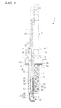
- FIG. 1 is a partially sectioned front view showing a spark plug 1. Note that in the description of FIG. 1 , a description will be given of a direction in which an axis CL1 of the spark plug 1 is a vertical direction in the drawing. Moreover, the lower side is the tip end side of the spark plug 1, and the upper side is the rear end side.
- the spark plug 1 includes a tubular insulator 2 and a tubular metal shell 3, which holds the insulator 2 therein, etc.
- the insulator 2 is formed from alumina or the like by sintering, as well known in the art.
- the insulator 2 externally includes a rear end trunk portion 10 formed on the rear end side, a large-diameter portion 11, an intermediate trunk portion 12, and an insulator nose length portion 13.
- the large-diameter portion 11 is located on the tip end side with respect to the rear end trunk portion 10 and formed to project radially outward.
- the intermediate trunk portion 12 is located on the tip end side with respect to the large-diameter portion 11 and is formed to be smaller in diameter than the large-diameter portion 11.
- the insulator nose length portion 13 is located on the tip end side with respect to the intermediate trunk portion 12 and is formed to be smaller in diameter than the intermediate trunk portion 12.
- the large-diameter portion 11, the intermediate trunk portion 12, and the greater portion of the insulator nose length portion 13 of the insulator 2 are accommodated within the metal shell 3.
- a shoulder portion 14 is formed at a connection portion between the intermediate trunk portion 12 and the insulator nose length portion 13 tapered off toward the tip end side.
- the insulator 2 is seated on the metal shell 3 along the shoulder portion 14.
- the insulator 2 has an axial hole 4 that extends along the axis CL1 and penetrates therethrough.
- a center electrode 5 is inserted into a tip end side of the axial hole 4.
- the center electrode 5 includes an inner layer 5A formed of metal excellent in thermal conductivity (for example, copper, copper alloy, and pure nickel (Ni)) and an outer layer 5B formed of an alloy that contains Ni as a main constituent.
- the center electrode 5 has a rodlike shape (a columnar shape) as a whole.
- the tip end portion of the center electrode 5 projects from the tip end of the insulator 2.
- a tip 31 including a metal excellent in wear resistance for example, iridium alloy and platinum alloy is provided at the tip end portion of the center electrode 5.
- a terminal nut electrode 6 is fixedly inserted into a rear end side of the axial hole 4 and projects from the rear end of the insulator 2.
- a columnar resistor 7 is disposed within the axial hole 4 between the center electrode 5 and the terminal nut electrode 6. Both end portions of the resistor 7 are electrically connected to the center electrode 5 and the terminal nut electrode 6, respectively, via electrically conductive glass seal layers 8 and 9.
- the metal shell 3 is made of a low-carbon steel or a like metal.
- the metal shell 3 is formed into a tubular shape extending along the axis CL1.
- the metal shell 3 includes a thread portion (a male thread portion) 15 at the outer periphery on the tip end side.
- the thread portion 15 is used to mount the spark plug 1 into the mounting hole of the combustion apparatus (for example, an internal combustion engine or a fuel cell reformer).
- the metal shell 3 includes a flange seat portion 16 located on the rear end side with respect to the thread portion 15.
- the seat portion 16 bulges radially outward.
- the cylindrically-shaped thread root portion 17 is disposed between the thread portion 15 and the seat portion 16.
- the metal shell 3 is small in diameter. That is, the thread size of the thread portion 15 is equal to or less than M12 or equal to or less than M10.
- a solid annular gasket 18 is engaged with the outer periphery of the thread root portion 17.
- the gasket 18 includes a predetermined metal (for example, a metal containing a copper or an iron as a main constituent).
- a rear end side face 18A of the gasket 18 contacts a seating portion 16A of the seat portion 16.
- the seating portion 16A is a surface that faces the gasket 18 side.
- a tip end side face 18B contacts the combustion apparatus.
- the tip end side face 18B includes an annular groove portion 18M on the inner peripheral side.
- the groove portion 18M places a central axis CL2 of the gasket 18 as the center.
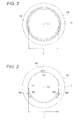
- an inner diameter K of the gasket 18 is smaller than the thread size of the thread portion 15.
- the inner peripheral portion of the gasket 18 needs not to project toward the inner peripheral side across the whole circumference.
- the inner peripheral portion of the gasket 18 may only partially project toward the inner peripheral side. Therefore, for example, as shown in FIG. 3 , a plurality of groove portions 18N may be intermittently disposed on the inner peripheral side of the tip end side face 18B along the circumferential direction.
- a plurality of protrusions 18P which projects toward the inner peripheral side of the gasket 18, is intermittently disposed along the circumferential direction.
- the inner diameter K of the gasket 18 is equivalent to a diameter of a hypothetical circle VL in contact with each protrusion 18P. The diameter becomes smaller than the thread size of the thread portion 15.
- the metal shell 3 includes, near the rear end side thereof, a tool engagement portion 19 having a hexagonal cross section.
- the tool engagement portion 19 allows a tool, such as a wrench, to be engaged when the spark plug 1 is mounted in the combustion apparatus.
- the metal shell 3 includes a caulking portion 20 provided at a rear end side with respect to the tool engagement portion 19. The caulking portion 20 is bent toward radially inward.
- a tapered shoulder portion 21 is formed at the inner periphery of the metal shell 3 to allow the insulator 2 to be seated on.
- the insulator 2 is inserted to the tip end side into the metal shell 3 from the rear end side of the metal shell 3.
- a rear-end opening portion of the metal shell 3 is caulked radially inward; that is, the caulking portion 20 is formed, whereby the insulator 2 is secured to the metal shell 3.
- An annular sheet packing 22 is interposed between the shoulder portion 14 and the shoulder portion 21.
- the sheet packing 22 retains air tightness in a combustion chamber.
- the sheet packing 22 reduces or prevents outward leakage of fuel gas which enters the clearance between the inner peripheral surface of the metal shell 3 and the insulator nose length portion 13 of the insulator 2, which is exposed to the combustion chamber.
- annular ring members 23 and 24 are interposed between the metal shell 3 and the insulator 2 at the rear end side of the metal shell 3.
- Powder of talc 25 is filled up between the ring members 23 and 24. That is, the metal shell 3 holds the insulator 2 via the sheet packing 22, the ring members 23 and 24, and the talc 25.
- a ground electrode 27 is sealed to a tip end portion 26 of the metal shell 3.
- the ground electrode 27 is bent at an approximately central portion thereof. Accordingly, the side face on the tip end side of the ground electrode 27 faces a tip end portion of the center electrode 5 (the tip 31).
- the ground electrode 27 includes an outer layer 27A formed of an alloy which contains Ni as a main constituent and an inner layer 27B formed of metal excellent in thermal conductivity (for example, copper, copper alloy, and pure Ni).
- a spark discharge gap 33 is formed between the tip end face of the center electrode 5 (the tip 31) and the tip end portion (the other end portion) of the ground electrode 27. Sparks are discharged at the spark discharge gap 33 in the direction almost along the axis CL1.
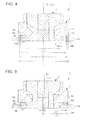
- a chamfering portion 18C is formed between the rear end side face 18A of the gasket 18 and the outer peripheral face of the gasket 18.
- the chamfering portion 18C has an outer diameter gradually increasing toward the tip end side. Accordingly, the outer diameter C (mm) of the rear end side face 18A of the gasket 18 in contact with the seating portion 16A when the spark plug 1 is mounted in a combustion apparatus EN becomes comparatively small.
- the outer diameter of the seating portion 16A is assumed as L (mm).
- the maximum shift distance (the maximum value) of the gasket 18 in contact with the seating portion 16A is assumed as A (mm).
- the gasket 18 is shiftable relative to the metal shell 3 along a direction orthogonal to the axis CL1, from a position where the axis CL1 and the central axis CL2 of the gasket 18 coincide.
- the maximum value A is a maximum value of the relative shift of the gasket 18.
- the spark plug 1 (or the gasket 18) is configured so as to satisfy C ⁇ L-2A.
- the maximum value A corresponds to the maximum distance where the gasket 18 with the axis CL1 and the central axis CL2 coinciding is shiftable to the direction orthogonal to the axis CL1.
- the spark plug 1 (or the gasket 18) is configured so as to satisfy L/2 ⁇ C/2 + A when the gasket 18 is most-shifted along the direction orthogonal to the axis CL1.
- the rear end side face 18A of the gasket 18 is always positioned on the inner peripheral side with respect to the outermost peripheral portion of the seating portion 16A.
- the spark plug I (or the gasket 18) is configured to satisfy 0.8L ⁇ C as shown in FIG. 4 .
- the spark plug 1 is configured so as to satisfy B ⁇ 0.75L.
- the spark plug 1 (or the gasket 18) is configured such that the area of the rear end side face 18A becomes a sufficient size according to the amount of the tightening torque (a force applied from the seating portion 16A to the rear end side face 18A). This reduces or prevents excessive increase of a pressure applied to the rear end side face 18A along the axis CL1 direction when the spark plug I is mounted in the combustion apparatus EN.
- An outer diameter D (mm) of the tip end side face 18B of the gasket 18 in contact with the combustion apparatus EN when the spark plug 1 is mounted in the combustion apparatus EN is designed larger than the outer diameter C (mm) of the rear end side face 18A.
- the spark plug 1 (or the gasket 18) is configured to satisfy C ⁇ L - 2A. This reduces or prevents fluctuation in the contact area of the rear end side face 18A of the gasket 18 and the seating portion 16A due to the shift of the gasket 18.
- the contact area of the rear end side face 18A of the gasket 18 and the seating portion 16A can be constant. This ensures a constant frictional contact resistance generated between the rear end side face 18A and the seating portion 16A when the spark plug 1 is mounted in the combustion apparatus EN.
- the ground electrode 27 can be accurately disposed in a predetermined position.
- the spark plug 1 (or the gasket 18) is configured to satisfy 0.8L ⁇ C and B ⁇ 0.75L.
- the area of the rear end side face 18A is sufficiently ensured corresponding to the size of the outer diameter C of the seating portion 16A (that is, an amount of a force applied from the seating portion 16A to the rear end side face 18A). Therefore, when the spark plug 1 is mounted in the combustion apparatus EN, pressure applied to the rear end side face 18A can be reduced or prevented from becoming excessively large. Accordingly, the rear end side face 18A can be further reliably reduced or prevented from being excessively collapsed and deformed. Consequently, a variation in the turning angle of the spark plug 1 can be further reliably reduced or prevented when the spark plug 1 is mounted in the combustion apparatus EN. As a result, the ground electrode can be further accurately disposed in a predetermined position.
- the outer diameter D of the tip end side face 18B is designed larger than the outer diameter C of the rear end side face 18A. In view of this, the contact area of the tip end side face 18B and the combustion apparatus EN can be sufficiently ensured. As a result, good air tightness can be achieved.
- the outer diameter D is designed sufficiently large. This allows reducing the sliding of the gasket 18 with respect to the combustion apparatus EN when the spark plug 1 is mounted in the combustion apparatus EN. This can efficiency reduce generating metal powder such as aluminum powder from the combustion apparatus EN in accordance with the sliding of the gasket 18. Accordingly, stability of a frictional state can be ensured between the tip end side face 18B and the combustion apparatus EN. In view of this, the ground electrode 27 can be further accurately disposed in a predetermined position.
- the thread size of the thread portion 15 is set equal to or less than M12 or equal to or less than M10. Accordingly, even a slight change in the area of contact between the seating portion 16A and the rear end side face 18A risks greatly varying the position where the ground electrode 27 is finally disposed.
- the spark plug 1 (or the gasket 18) is configured so that the contact area of the seating portion 16A and the rear end side face 18A is constant.
- the ground electrode 27 can be accurately disposed in a predetermined position.
- the configuration of this embodiment is especially effective when the thread size of the thread portion 15 is M 12 or equal to or less than M 10.
- Respective sets of thirty samples of the spark plugs where the thread sizes of the thread portions were M 10, M12, and M14 and the outer diameters C (mm) of the rear end side faces of the gaskets were variously changed were manufactured. A positioning-accuracy check test was performed on each sample.
- each sample was mounted in an aluminum bush for the test, which imitates an engine head of an internal combustion engine, with a predetermined tightening torque set to each thread size.
- the turning angle of the ground electrode with respect to the preliminarily-set reference position of each sample was measured.
- the standard deviation ⁇ of the turning angle of each sample (30 samples) was multiplied by 4 (4 ⁇ ).
- a small 4 ⁇ means a small variation in the arranged position of the ground electrode, that is, the ground electrode can be further accurately disposed in a predetermined position.
- a rate of improvement in 4 ⁇ of the sample satisfying C ⁇ L - 2A to 4 ⁇ of the sample satisfying C > L - 2A was calculated.
- 4 ⁇ of the sample satisfying C > L - 2A was assumed as s1.
- 4 ⁇ of the sample satisfying C ⁇ L - 2A was assumed as s2.
- the rate of improvement is calculated by (s1 - s2)/s1.
- a large rate of improvement means that the operational advantages by satisfying C ⁇ L - 2A is considerable.
- each sample was mounted in the aluminum bush with a predetermined tightening torque set to each thread size. Then, air pressure of 1.5 MPa was applied to the tip end portion of each sample. A leakage amount of air from between: the gasket, and the metal shell and the aluminum bush were measured.
- the sample with the leakage amount of less than 1 cc/min was regarded as excellent in air tightness and evaluated as "o".
- the sample with the leakage amount of equal to or more than 1 mm/min was regarded to be inferior in air tightness and evaluated as " ⁇ ".
- Table I shows the test results of the positioning-accuracy check test and the air tightness evaluation test.
- the samples with the thread size of M10 were mounted to the aluminum bushes with the tightening torque of 12N•m.
- the tightening torque of the samples with the thread size of M12 was 20N•m
- the tightening torque of the samples with the thread size of M14 was 30N•m.
- satisfying 0.8L ⁇ C ⁇ L - 2A and B ⁇ 0.75L are preferred from a perspective of ensuring good air tightness while the ground electrode is accurately locatable in a predetermined position when the spark plug is mounted in the internal combustion engine or similar.
- Satisfying 0.8 L ⁇ C ⁇ L - 2A and B ⁇ 0.75L is specifically meaningful for the spark plug with the thread size of the thread portion of equal to or less than M 12 where the arranged position of the ground electrode is prone to vary. Satisfying 0.8L ⁇ C ⁇ L - 2A and B ⁇ 0.75L is extremely meaningful for the spark plug with the thread size of the thread portion of equal to or less than M10 where the arranged position of the ground electrode is further prone to vary.
- the technique according to the disclosure is not limited to the description of the embodiment.
- the technique according to the disclosure may be, for example, implemented as follows.
- the technique according to the disclosure is also possible to be implemented as other applications and alterations, not exemplified below.
Landscapes
- Chemical & Material Sciences (AREA)
- Engineering & Computer Science (AREA)
- Combustion & Propulsion (AREA)
- Spark Plugs (AREA)
- Ignition Installations For Internal Combustion Engines (AREA)
- Gasket Seals (AREA)
Applications Claiming Priority (1)
| Application Number | Priority Date | Filing Date | Title |
|---|---|---|---|
| JP2012258156A JP5629300B2 (ja) | 2012-11-27 | 2012-11-27 | 点火プラグ |
Publications (3)
| Publication Number | Publication Date |
|---|---|
| EP2736131A2 true EP2736131A2 (de) | 2014-05-28 |
| EP2736131A3 EP2736131A3 (de) | 2015-04-08 |
| EP2736131B1 EP2736131B1 (de) | 2018-11-14 |
Family
ID=49639804
Family Applications (1)
| Application Number | Title | Priority Date | Filing Date |
|---|---|---|---|
| EP13194620.4A Active EP2736131B1 (de) | 2012-11-27 | 2013-11-27 | Zündkerze |
Country Status (3)
| Country | Link |
|---|---|
| US (1) | US8952603B2 (de) |
| EP (1) | EP2736131B1 (de) |
| JP (1) | JP5629300B2 (de) |
Cited By (3)
| Publication number | Priority date | Publication date | Assignee | Title |
|---|---|---|---|---|
| US20180034245A1 (en) * | 2016-07-28 | 2018-02-01 | Denso Corporation | Spark plug, spark plug gasket, and manufacturing method thereof |
| DE102021214326A1 (de) | 2021-12-14 | 2023-06-15 | Robert Bosch Gesellschaft mit beschränkter Haftung | Dichtscheibe einer Zündkerze |
| DE102018107259B4 (de) | 2017-04-12 | 2024-09-26 | Niterra Co., Ltd. | Zündkerze und Verbrennungsmotor umfassend dieselbe |
Families Citing this family (2)
| Publication number | Priority date | Publication date | Assignee | Title |
|---|---|---|---|---|
| DE102017109844B4 (de) | 2017-05-08 | 2019-08-14 | Federal-Mogul Ignition Gmbh | Verfahren zum Herstellen einer Zündkerzenanordnung und Zündkerzenanordnung |
| DE102019126831B4 (de) | 2018-10-11 | 2025-01-30 | Federal-Mogul Ignition Llc | Zündkerze |
Citations (2)
| Publication number | Priority date | Publication date | Assignee | Title |
|---|---|---|---|---|
| JP2006236906A (ja) | 2005-02-28 | 2006-09-07 | Ngk Spark Plug Co Ltd | スパークプラグの製造方法 |
| JP2008135370A (ja) | 2006-10-30 | 2008-06-12 | Ngk Spark Plug Co Ltd | 内燃機関用スパークプラグ及びその製造方法 |
Family Cites Families (10)
| Publication number | Priority date | Publication date | Assignee | Title |
|---|---|---|---|---|
| US2941105A (en) * | 1952-08-02 | 1960-06-14 | Avco Mfg Corp | Gasket |
| GB900231A (en) * | 1957-10-04 | 1962-07-04 | Henry Anderson Spencer | Means for controlling axial loads on bolts or the like |
| JP4104211B2 (ja) * | 1998-06-10 | 2008-06-18 | 日本特殊陶業株式会社 | ガスケット及びガスケットを有するねじ付部材 |
| JP3062153U (ja) * | 1999-03-15 | 1999-09-28 | 株式会社共和電業 | 圧力計 |
| JP4296202B2 (ja) * | 2007-02-27 | 2009-07-15 | 日本特殊陶業株式会社 | スパークプラグの製造方法およびその製造方法により製造されたスパークプラグ |
| JP4436398B2 (ja) * | 2007-10-09 | 2010-03-24 | 日本特殊陶業株式会社 | スパークプラグ用の封止部材およびスパークプラグ |
| US8766521B2 (en) * | 2010-08-03 | 2014-07-01 | Ngk Spark Plug Co., Ltd. | Spark plug |
| JP2013016296A (ja) * | 2011-07-01 | 2013-01-24 | Ngk Spark Plug Co Ltd | 点火プラグ及びガスケット |
| JP2013089525A (ja) * | 2011-10-20 | 2013-05-13 | Denso Corp | スパークプラグの取付構造 |
| EP2789064B1 (de) * | 2011-12-09 | 2018-04-25 | Federal-Mogul Ignition Company | Isolator mit verbesserter stabilität durch angepasste sitzgeometrie |
-
2012
- 2012-11-27 JP JP2012258156A patent/JP5629300B2/ja active Active
-
2013
- 2013-11-21 US US14/086,224 patent/US8952603B2/en active Active
- 2013-11-27 EP EP13194620.4A patent/EP2736131B1/de active Active
Patent Citations (2)
| Publication number | Priority date | Publication date | Assignee | Title |
|---|---|---|---|---|
| JP2006236906A (ja) | 2005-02-28 | 2006-09-07 | Ngk Spark Plug Co Ltd | スパークプラグの製造方法 |
| JP2008135370A (ja) | 2006-10-30 | 2008-06-12 | Ngk Spark Plug Co Ltd | 内燃機関用スパークプラグ及びその製造方法 |
Cited By (4)
| Publication number | Priority date | Publication date | Assignee | Title |
|---|---|---|---|---|
| US20180034245A1 (en) * | 2016-07-28 | 2018-02-01 | Denso Corporation | Spark plug, spark plug gasket, and manufacturing method thereof |
| US10177536B2 (en) * | 2016-07-28 | 2019-01-08 | Denso Corporation | Spark plug, spark plug gasket, and manufacturing method thereof |
| DE102018107259B4 (de) | 2017-04-12 | 2024-09-26 | Niterra Co., Ltd. | Zündkerze und Verbrennungsmotor umfassend dieselbe |
| DE102021214326A1 (de) | 2021-12-14 | 2023-06-15 | Robert Bosch Gesellschaft mit beschränkter Haftung | Dichtscheibe einer Zündkerze |
Also Published As
| Publication number | Publication date |
|---|---|
| US8952603B2 (en) | 2015-02-10 |
| EP2736131B1 (de) | 2018-11-14 |
| EP2736131A3 (de) | 2015-04-08 |
| JP2014107075A (ja) | 2014-06-09 |
| US20140145583A1 (en) | 2014-05-29 |
| JP5629300B2 (ja) | 2014-11-19 |
Similar Documents
| Publication | Publication Date | Title |
|---|---|---|
| KR101522054B1 (ko) | 내연 엔진용 스파크 플러그 및 스파크 플러그 제조 방법 | |
| US9843166B2 (en) | Spark plug and method for manufacturing spark plug | |
| US8115371B2 (en) | Spark plug | |
| EP2736131B1 (de) | Zündkerze | |
| CN103503256B (zh) | 火花塞及其组装结构 | |
| US8729785B2 (en) | Spark plug | |
| CN102257687A (zh) | 内燃机用火花塞 | |
| EP2916403B1 (de) | Zündkerze | |
| EP2763250B1 (de) | Zündkerze und Verfahren zur Herstellung davon | |
| US20060202599A1 (en) | Spark plug | |
| US8981633B2 (en) | Spark plug and production method therefor | |
| JP4648485B1 (ja) | スパークプラグ | |
| EP2800216B1 (de) | Zündkerze | |
| EP2469668B1 (de) | Zündkerze | |
| KR101579022B1 (ko) | 점화 플러그 | |
| US9876332B2 (en) | Spark plug capable of restraining lateral sparking | |
| EP3065238B1 (de) | Zündkerze | |
| JP2013016296A (ja) | 点火プラグ及びガスケット | |
| JP2013016295A (ja) | スパークプラグ | |
| JP5698686B2 (ja) | スパークプラグ | |
| JP7039519B2 (ja) | 点火プラグ | |
| JPWO2019069640A1 (ja) | 点火プラグ | |
| JP2009140674A (ja) | ガスエンジン用スパークプラグ |
Legal Events
| Date | Code | Title | Description |
|---|---|---|---|
| PUAI | Public reference made under article 153(3) epc to a published international application that has entered the european phase |
Free format text: ORIGINAL CODE: 0009012 |
|
| 17P | Request for examination filed |
Effective date: 20131127 |
|
| AK | Designated contracting states |
Kind code of ref document: A2 Designated state(s): AL AT BE BG CH CY CZ DE DK EE ES FI FR GB GR HR HU IE IS IT LI LT LU LV MC MK MT NL NO PL PT RO RS SE SI SK SM TR |
|
| AX | Request for extension of the european patent |
Extension state: BA ME |
|
| PUAL | Search report despatched |
Free format text: ORIGINAL CODE: 0009013 |
|
| AK | Designated contracting states |
Kind code of ref document: A3 Designated state(s): AL AT BE BG CH CY CZ DE DK EE ES FI FR GB GR HR HU IE IS IT LI LT LU LV MC MK MT NL NO PL PT RO RS SE SI SK SM TR |
|
| AX | Request for extension of the european patent |
Extension state: BA ME |
|
| RIC1 | Information provided on ipc code assigned before grant |
Ipc: H01T 13/08 20060101AFI20150227BHEP |
|
| R17P | Request for examination filed (corrected) |
Effective date: 20150930 |
|
| RBV | Designated contracting states (corrected) |
Designated state(s): AL AT BE BG CH CY CZ DE DK EE ES FI FR GB GR HR HU IE IS IT LI LT LU LV MC MK MT NL NO PL PT RO RS SE SI SK SM TR |
|
| GRAP | Despatch of communication of intention to grant a patent |
Free format text: ORIGINAL CODE: EPIDOSNIGR1 |
|
| INTG | Intention to grant announced |
Effective date: 20180706 |
|
| RAP1 | Party data changed (applicant data changed or rights of an application transferred) |
Owner name: NGK SPARK PLUG CO., LTD. |
|
| GRAS | Grant fee paid |
Free format text: ORIGINAL CODE: EPIDOSNIGR3 |
|
| GRAA | (expected) grant |
Free format text: ORIGINAL CODE: 0009210 |
|
| AK | Designated contracting states |
Kind code of ref document: B1 Designated state(s): AL AT BE BG CH CY CZ DE DK EE ES FI FR GB GR HR HU IE IS IT LI LT LU LV MC MK MT NL NO PL PT RO RS SE SI SK SM TR |
|
| REG | Reference to a national code |
Ref country code: CH Ref legal event code: EP Ref country code: AT Ref legal event code: REF Ref document number: 1065957 Country of ref document: AT Kind code of ref document: T Effective date: 20181115 |
|
| REG | Reference to a national code |
Ref country code: DE Ref legal event code: R096 Ref document number: 602013046594 Country of ref document: DE |
|
| REG | Reference to a national code |
Ref country code: IE Ref legal event code: FG4D |
|
| REG | Reference to a national code |
Ref country code: NL Ref legal event code: MP Effective date: 20181114 |
|
| REG | Reference to a national code |
Ref country code: LT Ref legal event code: MG4D |
|
| REG | Reference to a national code |
Ref country code: AT Ref legal event code: MK05 Ref document number: 1065957 Country of ref document: AT Kind code of ref document: T Effective date: 20181114 |
|
| PG25 | Lapsed in a contracting state [announced via postgrant information from national office to epo] |
Ref country code: LV Free format text: LAPSE BECAUSE OF FAILURE TO SUBMIT A TRANSLATION OF THE DESCRIPTION OR TO PAY THE FEE WITHIN THE PRESCRIBED TIME-LIMIT Effective date: 20181114 Ref country code: HR Free format text: LAPSE BECAUSE OF FAILURE TO SUBMIT A TRANSLATION OF THE DESCRIPTION OR TO PAY THE FEE WITHIN THE PRESCRIBED TIME-LIMIT Effective date: 20181114 Ref country code: AT Free format text: LAPSE BECAUSE OF FAILURE TO SUBMIT A TRANSLATION OF THE DESCRIPTION OR TO PAY THE FEE WITHIN THE PRESCRIBED TIME-LIMIT Effective date: 20181114 Ref country code: FI Free format text: LAPSE BECAUSE OF FAILURE TO SUBMIT A TRANSLATION OF THE DESCRIPTION OR TO PAY THE FEE WITHIN THE PRESCRIBED TIME-LIMIT Effective date: 20181114 Ref country code: NO Free format text: LAPSE BECAUSE OF FAILURE TO SUBMIT A TRANSLATION OF THE DESCRIPTION OR TO PAY THE FEE WITHIN THE PRESCRIBED TIME-LIMIT Effective date: 20190214 Ref country code: BG Free format text: LAPSE BECAUSE OF FAILURE TO SUBMIT A TRANSLATION OF THE DESCRIPTION OR TO PAY THE FEE WITHIN THE PRESCRIBED TIME-LIMIT Effective date: 20190214 Ref country code: LT Free format text: LAPSE BECAUSE OF FAILURE TO SUBMIT A TRANSLATION OF THE DESCRIPTION OR TO PAY THE FEE WITHIN THE PRESCRIBED TIME-LIMIT Effective date: 20181114 Ref country code: ES Free format text: LAPSE BECAUSE OF FAILURE TO SUBMIT A TRANSLATION OF THE DESCRIPTION OR TO PAY THE FEE WITHIN THE PRESCRIBED TIME-LIMIT Effective date: 20181114 Ref country code: IS Free format text: LAPSE BECAUSE OF FAILURE TO SUBMIT A TRANSLATION OF THE DESCRIPTION OR TO PAY THE FEE WITHIN THE PRESCRIBED TIME-LIMIT Effective date: 20190314 |
|
| PG25 | Lapsed in a contracting state [announced via postgrant information from national office to epo] |
Ref country code: RS Free format text: LAPSE BECAUSE OF FAILURE TO SUBMIT A TRANSLATION OF THE DESCRIPTION OR TO PAY THE FEE WITHIN THE PRESCRIBED TIME-LIMIT Effective date: 20181114 Ref country code: GR Free format text: LAPSE BECAUSE OF FAILURE TO SUBMIT A TRANSLATION OF THE DESCRIPTION OR TO PAY THE FEE WITHIN THE PRESCRIBED TIME-LIMIT Effective date: 20190215 Ref country code: NL Free format text: LAPSE BECAUSE OF FAILURE TO SUBMIT A TRANSLATION OF THE DESCRIPTION OR TO PAY THE FEE WITHIN THE PRESCRIBED TIME-LIMIT Effective date: 20181114 Ref country code: PT Free format text: LAPSE BECAUSE OF FAILURE TO SUBMIT A TRANSLATION OF THE DESCRIPTION OR TO PAY THE FEE WITHIN THE PRESCRIBED TIME-LIMIT Effective date: 20190314 Ref country code: SE Free format text: LAPSE BECAUSE OF FAILURE TO SUBMIT A TRANSLATION OF THE DESCRIPTION OR TO PAY THE FEE WITHIN THE PRESCRIBED TIME-LIMIT Effective date: 20181114 Ref country code: AL Free format text: LAPSE BECAUSE OF FAILURE TO SUBMIT A TRANSLATION OF THE DESCRIPTION OR TO PAY THE FEE WITHIN THE PRESCRIBED TIME-LIMIT Effective date: 20181114 |
|
| REG | Reference to a national code |
Ref country code: CH Ref legal event code: PL |
|
| PG25 | Lapsed in a contracting state [announced via postgrant information from national office to epo] |
Ref country code: DK Free format text: LAPSE BECAUSE OF FAILURE TO SUBMIT A TRANSLATION OF THE DESCRIPTION OR TO PAY THE FEE WITHIN THE PRESCRIBED TIME-LIMIT Effective date: 20181114 Ref country code: PL Free format text: LAPSE BECAUSE OF FAILURE TO SUBMIT A TRANSLATION OF THE DESCRIPTION OR TO PAY THE FEE WITHIN THE PRESCRIBED TIME-LIMIT Effective date: 20181114 Ref country code: CZ Free format text: LAPSE BECAUSE OF FAILURE TO SUBMIT A TRANSLATION OF THE DESCRIPTION OR TO PAY THE FEE WITHIN THE PRESCRIBED TIME-LIMIT Effective date: 20181114 Ref country code: IT Free format text: LAPSE BECAUSE OF FAILURE TO SUBMIT A TRANSLATION OF THE DESCRIPTION OR TO PAY THE FEE WITHIN THE PRESCRIBED TIME-LIMIT Effective date: 20181114 Ref country code: LU Free format text: LAPSE BECAUSE OF NON-PAYMENT OF DUE FEES Effective date: 20181127 |
|
| REG | Reference to a national code |
Ref country code: DE Ref legal event code: R097 Ref document number: 602013046594 Country of ref document: DE |
|
| REG | Reference to a national code |
Ref country code: BE Ref legal event code: MM Effective date: 20181130 |
|
| REG | Reference to a national code |
Ref country code: IE Ref legal event code: MM4A |
|
| PG25 | Lapsed in a contracting state [announced via postgrant information from national office to epo] |
Ref country code: CH Free format text: LAPSE BECAUSE OF NON-PAYMENT OF DUE FEES Effective date: 20181130 Ref country code: MC Free format text: LAPSE BECAUSE OF FAILURE TO SUBMIT A TRANSLATION OF THE DESCRIPTION OR TO PAY THE FEE WITHIN THE PRESCRIBED TIME-LIMIT Effective date: 20181114 Ref country code: SK Free format text: LAPSE BECAUSE OF FAILURE TO SUBMIT A TRANSLATION OF THE DESCRIPTION OR TO PAY THE FEE WITHIN THE PRESCRIBED TIME-LIMIT Effective date: 20181114 Ref country code: SM Free format text: LAPSE BECAUSE OF FAILURE TO SUBMIT A TRANSLATION OF THE DESCRIPTION OR TO PAY THE FEE WITHIN THE PRESCRIBED TIME-LIMIT Effective date: 20181114 Ref country code: EE Free format text: LAPSE BECAUSE OF FAILURE TO SUBMIT A TRANSLATION OF THE DESCRIPTION OR TO PAY THE FEE WITHIN THE PRESCRIBED TIME-LIMIT Effective date: 20181114 Ref country code: RO Free format text: LAPSE BECAUSE OF FAILURE TO SUBMIT A TRANSLATION OF THE DESCRIPTION OR TO PAY THE FEE WITHIN THE PRESCRIBED TIME-LIMIT Effective date: 20181114 Ref country code: LI Free format text: LAPSE BECAUSE OF NON-PAYMENT OF DUE FEES Effective date: 20181130 |
|
| PLBE | No opposition filed within time limit |
Free format text: ORIGINAL CODE: 0009261 |
|
| STAA | Information on the status of an ep patent application or granted ep patent |
Free format text: STATUS: NO OPPOSITION FILED WITHIN TIME LIMIT |
|
| 26N | No opposition filed |
Effective date: 20190815 |
|
| GBPC | Gb: european patent ceased through non-payment of renewal fee |
Effective date: 20190214 |
|
| PG25 | Lapsed in a contracting state [announced via postgrant information from national office to epo] |
Ref country code: SI Free format text: LAPSE BECAUSE OF FAILURE TO SUBMIT A TRANSLATION OF THE DESCRIPTION OR TO PAY THE FEE WITHIN THE PRESCRIBED TIME-LIMIT Effective date: 20181114 Ref country code: IE Free format text: LAPSE BECAUSE OF NON-PAYMENT OF DUE FEES Effective date: 20181127 Ref country code: FR Free format text: LAPSE BECAUSE OF NON-PAYMENT OF DUE FEES Effective date: 20190114 |
|
| PG25 | Lapsed in a contracting state [announced via postgrant information from national office to epo] |
Ref country code: BE Free format text: LAPSE BECAUSE OF NON-PAYMENT OF DUE FEES Effective date: 20181130 |
|
| PG25 | Lapsed in a contracting state [announced via postgrant information from national office to epo] |
Ref country code: MT Free format text: LAPSE BECAUSE OF NON-PAYMENT OF DUE FEES Effective date: 20181127 Ref country code: GB Free format text: LAPSE BECAUSE OF NON-PAYMENT OF DUE FEES Effective date: 20190214 |
|
| PG25 | Lapsed in a contracting state [announced via postgrant information from national office to epo] |
Ref country code: TR Free format text: LAPSE BECAUSE OF FAILURE TO SUBMIT A TRANSLATION OF THE DESCRIPTION OR TO PAY THE FEE WITHIN THE PRESCRIBED TIME-LIMIT Effective date: 20181114 |
|
| PG25 | Lapsed in a contracting state [announced via postgrant information from national office to epo] |
Ref country code: HU Free format text: LAPSE BECAUSE OF FAILURE TO SUBMIT A TRANSLATION OF THE DESCRIPTION OR TO PAY THE FEE WITHIN THE PRESCRIBED TIME-LIMIT; INVALID AB INITIO Effective date: 20131127 Ref country code: CY Free format text: LAPSE BECAUSE OF FAILURE TO SUBMIT A TRANSLATION OF THE DESCRIPTION OR TO PAY THE FEE WITHIN THE PRESCRIBED TIME-LIMIT Effective date: 20181114 Ref country code: MK Free format text: LAPSE BECAUSE OF NON-PAYMENT OF DUE FEES Effective date: 20181114 |
|
| P01 | Opt-out of the competence of the unified patent court (upc) registered |
Effective date: 20230512 |
|
| REG | Reference to a national code |
Ref country code: DE Ref legal event code: R081 Ref document number: 602013046594 Country of ref document: DE Owner name: NITERRA CO., LTD., NAGOYA-SHI, JP Free format text: FORMER OWNER: NGK SPARK PLUG CO., LTD., NAGOYA-SHI, AICHI-KEN, JP |
|
| PGFP | Annual fee paid to national office [announced via postgrant information from national office to epo] |
Ref country code: DE Payment date: 20250930 Year of fee payment: 13 |