EP2734304B1 - Rollenmühle und verfahren zum betreiben einer rollenmühle - Google Patents
Rollenmühle und verfahren zum betreiben einer rollenmühle Download PDFInfo
- Publication number
- EP2734304B1 EP2734304B1 EP13700910.6A EP13700910A EP2734304B1 EP 2734304 B1 EP2734304 B1 EP 2734304B1 EP 13700910 A EP13700910 A EP 13700910A EP 2734304 B1 EP2734304 B1 EP 2734304B1
- Authority
- EP
- European Patent Office
- Prior art keywords
- grinding
- water
- ground
- roller
- fact
- Prior art date
- Legal status (The legal status is an assumption and is not a legal conclusion. Google has not performed a legal analysis and makes no representation as to the accuracy of the status listed.)
- Not-in-force
Links
- 238000000034 method Methods 0.000 title claims description 10
- XLYOFNOQVPJJNP-UHFFFAOYSA-N water Substances O XLYOFNOQVPJJNP-UHFFFAOYSA-N 0.000 claims description 80
- 239000000463 material Substances 0.000 claims description 41
- 238000012423 maintenance Methods 0.000 claims description 3
- 238000001514 detection method Methods 0.000 description 4
- 238000002347 injection Methods 0.000 description 3
- 239000007924 injection Substances 0.000 description 3
- 238000005096 rolling process Methods 0.000 description 3
- 230000006978 adaptation Effects 0.000 description 1
- 230000001419 dependent effect Effects 0.000 description 1
- 238000006073 displacement reaction Methods 0.000 description 1
- 230000006641 stabilisation Effects 0.000 description 1
- 238000011105 stabilization Methods 0.000 description 1
- 230000000087 stabilizing effect Effects 0.000 description 1
Images



Classifications
-
- B—PERFORMING OPERATIONS; TRANSPORTING
- B02—CRUSHING, PULVERISING, OR DISINTEGRATING; PREPARATORY TREATMENT OF GRAIN FOR MILLING
- B02C—CRUSHING, PULVERISING, OR DISINTEGRATING IN GENERAL; MILLING GRAIN
- B02C23/00—Auxiliary methods or auxiliary devices or accessories specially adapted for crushing or disintegrating not provided for in preceding groups or not specially adapted to apparatus covered by a single preceding group
- B02C23/18—Adding fluid, other than for crushing or disintegrating by fluid energy
-
- B—PERFORMING OPERATIONS; TRANSPORTING
- B02—CRUSHING, PULVERISING, OR DISINTEGRATING; PREPARATORY TREATMENT OF GRAIN FOR MILLING
- B02C—CRUSHING, PULVERISING, OR DISINTEGRATING IN GENERAL; MILLING GRAIN
- B02C15/00—Disintegrating by milling members in the form of rollers or balls co-operating with rings or discs
-
- B—PERFORMING OPERATIONS; TRANSPORTING
- B02—CRUSHING, PULVERISING, OR DISINTEGRATING; PREPARATORY TREATMENT OF GRAIN FOR MILLING
- B02C—CRUSHING, PULVERISING, OR DISINTEGRATING IN GENERAL; MILLING GRAIN
- B02C15/00—Disintegrating by milling members in the form of rollers or balls co-operating with rings or discs
- B02C15/007—Mills with rollers pressed against a rotary horizontal disc
-
- B—PERFORMING OPERATIONS; TRANSPORTING
- B02—CRUSHING, PULVERISING, OR DISINTEGRATING; PREPARATORY TREATMENT OF GRAIN FOR MILLING
- B02C—CRUSHING, PULVERISING, OR DISINTEGRATING IN GENERAL; MILLING GRAIN
- B02C15/00—Disintegrating by milling members in the form of rollers or balls co-operating with rings or discs
- B02C15/04—Mills with pressed pendularly-mounted rollers, e.g. spring pressed
Definitions
- the invention relates to a roller mill for grinding regrind with a grinding table and at least one cooperating with the grinding table grinding roller and a method for operating such a roller mill as these are known for example from JPH 07 204 528 A.
- the ground material In roller mills the ground material is usually given up centrally and passes through centrifugal force to the outside, where it is detected by rolling on the grinding table grinding rollers. From the EP 0 858 839 A1 it is already known that a moistening of the ground material causes stabilization of the grinding bed and in this way the smoothness of the roller mill and the efficiency of grinding can be improved. It is known to supply the water together with the material to be ground or directly at the delivery point on the grinding table. In the EP 0 858 839 A1 a water lance is used, which is arranged in the direction of rotation of the grinding plate before the grinding roller.
- the volume flow of the sprayed water is controlled in response to a vibration sensor. If a certain vibration level is exceeded, the injected water volume flow is increased and vice versa.
- the invention is therefore based on the object to make the task of water on the grinding bed even more efficient, on the one hand to positively influence the smoothness of the roller mill and to optimize the efficiency of grinding and throughput of the roller mill and on the other hand to get along with the smallest possible water flow rates.
- this object is achieved by a roller mill with the features of claim 1 and by a method having the features of claim 6.
- the roller mill according to the invention for grinding regrind has a grinding plate and at least one co-rotating with the grinding plate grinding roller, wherein a water lance for applying water to the material to be ground in the direction of rotation of the grinding plate is arranged in front of the grinding roller.
- the water lance is rotatably formed and means for rotating the water lance are provided in order to influence the action time of the water on the ground material before the ground material is detected by the grinding roller, specifically.
- a grinding plate and at least one grinding roller cooperating with the grinding plate are provided. Furthermore, water is applied to the ground material via a water lance arranged in the direction of rotation of the grinding table in front of the grinding roller.
- the action time of the water on the material to be ground before the grinding roller detects the material to be ground is influenced by the fact that the distance between the impact of the water on the material to be ground and the detection of the material to be ground by the grinding roller is adjusted by rotation of the water lance.
- the water lance expediently has a plurality of nozzles with nozzle axes aligned in the direction of the grinding disk in order to cover the entire width of the grinding material flow to be detected by the grinding roller.
- the means for rotating the water lance are preferably designed such that the distance between the impact of the water on the ground material and the detection of the ground material through the grinding roller by a rotation of the water lance is variable.
- a grinding path is formed in the active region of the grinding roller, wherein the water lance expediently extends transversely to this grinding path and thus radially to the grinding table.
- the water lance is additionally arranged to be displaceable in the direction of its longitudinal extent. In this way, a further adaptation and alignment of the water jets is possible.
- the lance can be pulled out of the grinding chamber in the maintenance and / or repair case in this way. If this is possible during operation, the grinding process does not have to be interrupted.
- the rotation of the water lance is expediently carried out as a function of at least one operating parameter (for example fluctuations in the power consumption of the drive, fluctuations in the hydraulic pressure, grinding bed height, theoretical rolling points of the grinding rollers).
- at least one operating parameter for example fluctuations in the power consumption of the drive, fluctuations in the hydraulic pressure, grinding bed height, theoretical rolling points of the grinding rollers.
- the illustrated roller mill essentially has a grinding table 1 and two grinding rollers 2 cooperating with the grinding table.
- each grinding roller 2 is associated with a water lance 3, which is arranged in the direction of rotation of the grinding table 1 before each grinding roller 2.
- the grinding roller 2 and the grinding table 1 are arranged in a limited by a mill housing 5 grinding chamber.
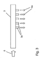
- water lance 3 is here designed as an elongated pipe section, which has on the grinding table 1 side facing a plurality of nozzles 3a.
- the water lance 3 supplied water 6 is injected in the form of emerging from the nozzles 3a water jets 6a on the grinding table 1 supplied millbase 7.
- the water lance is according to the double arrow 8 ( Fig. 1 ) via means 9 rotatable.
- the nozzles 3a of the water lance 3 can in particular the in Fig. 4b . 5b and 6b represented position with respect to the grinding table 1 and the associated grinding roller 2.
- the water lance is also slidably disposed in the direction of its longitudinal extent according to the double arrow 10 and can be pulled out in particular from the mill housing 5, for example for maintenance or repair purposes.
- the adjustment according to the double arrows 8 and 10 can be done in particular during the ongoing grinding operation.
- the material to be ground 7 is usually placed centrally on the grinding table 1, and then moves due to the centrifugal force according to the dashed arrows 11 to the outside, where it comes in the region of the grinding path 12 on which the grinding rollers 2 roll on the grinding table 1.
- the location and direction with which the material to be ground 7 in the Area of the grinding path is different, as in the Fig. 4a .
- 5a and 6a is shown schematically for three different situations.
- this distance is a 1 shortest and in the position according to Fig. 6a and 6b (Distance a 2 ) the longest, while the Fig. 4a and 4b show a mean distance a 3 .
- the impact area of the water jets 6a on the ground material 7 can be influenced in a targeted manner.
- the water injection can be optimally adjusted to the present operating conditions of the roller mill.
- the exposure time of the water in the ground material 7 to the detection of the grinding roller 2 can be selectively influenced and the water injection is focused on a localized area. As a result, the necessary volume flow for stabilizing the grinding bed can be minimized, since an alignment of the injected water volume flow can be made to the most effective range.
- the means 9 are set for turning to rotate and / or radial displacement of the water lance 3 as a function of at least one operating parameter.
- operating parameters for example, the fluctuation of the power consumption of the drives for the grinding table 1 and / or the grinding rollers 2, fluctuations in the hydraulic contact pressure of the grinding rollers 2, the Mahlbettière or the theoretical rolling point of the grinding rollers 2 can be used.
- the above-described rotatable water lance for water injection is particularly suitable for roller mills with varying grinding materials or grinding properties.
Landscapes
- Engineering & Computer Science (AREA)
- Food Science & Technology (AREA)
- Crushing And Grinding (AREA)
Description
- Die Erfindung betrifft eine Rollenmühle zum Mahlen von Mahlgut mit einem Mahlteller und wenigstens einer mit dem Mahlteller zusammenwirkenden Mahlrolle sowie ein Verfahren zum Betreiben einer solchen Rollenmühle wie diese beispielsweise aus JPH 07 204 528 A bekannt sind.
- Bei Rollenmühlen wird das Mahlgut meist zentral aufgegeben und gelangt durch Fliehkraft nach außen und wird dort von den auf dem Mahlteller abrollenden Mahlrollen erfasst. Aus der
EP 0 858 839 A1 ist es bereits bekannt, dass eine Befeuchtung des Mahlgutes eine Stabilisierung des Mahlbettes bewirkt und auf diese Weise die Laufruhe der Rollenmühle sowie die Effizienz der Mahlung verbessert werden kann. Es ist bekannt, das Wasser zusammen mit dem Mahlgut oder direkt am Aufgabepunkt auf den Mahlteller zuzuführen. In derEP 0 858 839 A1 wird eine Wasserlanze verwendet, die in Drehrichtung des Mahltellers vor der Mahlrolle angeordnet ist. - Allerdings hat man festgestellt, dass die Produktqualität durch zu hohe eingespritzte Wasservolumenströme negativ beeinflusst wird. Außerdem kann die Verfügbarkeit von Wasser regional begrenzt sein.
- In der
JP 2000157882 A - Der Erfindung liegt daher die Aufgabe zugrunde, die Aufgabe des Wassers auf das Mahlbett noch effizienter zu gestalten, um einerseits die Laufruhe der Rollenmühle positiv zu beeinflussen sowie die Effizienz der Mahlung und den Durchsatz der Rollenmühle zu optimieren und andererseits mit möglichst kleinen Wasservolumenströmen auszukommen.
- Erfindungsgemäß wird diese Aufgabe durch eine Rollenmühle mit den Merkmalen des Anspruchs 1 sowie durch ein Verfahren mit den Merkmalen des Anspruchs 6 gelöst.
- Die erfindungsgemäß Rollenmühle zur Mahlung von Mahlgut weist einen Mahlteller und wenigstens eine mit dem Mahlteller zusammenwirkende Mahlrolle auf, wobei eine Wasserlanze zum Aufbringen von Wasser auf das Mahlgut in Drehrichtung des Mahltellers vor der Mahlrolle angeordnet ist. Die Wasserlanze ist dabei drehbar ausgebildet und es sind Mittel zum Drehen der Wasserlanze vorgesehen, um die Einwirkzeit des Wassers auf dem Mahlgut, bevor das Mahlgut von der Mahlrolle erfasst wird, gezielt zu beeinflussen.
- Beim erfindungsgemäßen Verfahren zum Betreiben einer Rollenmühle wird ein Mahlteller und wenigstens einer mit dem Mahlteller zusammenwirkende Mahlrolle bereitgestellt. Weiterhin wird über eine in Drehrichtung des Mahltellers vor der Mahlrolle angeordnete Wasserlanze Wasser auf das Mahlgut aufgebracht. Die Einwirkzeit des Wassers auf dem Mahlgut, bevor die Mahlrolle das Mahlgut erfasst, wird dadurch beeinflusst, dass der Abstand zwischen dem Auftreffen des Wassers auf das Mahlgut und dem Erfassen des Mahlguts durch die Mahlrolle durch Drehung der Wasserlanze gezielt eingestellt wird.
- Bei den der Erfindung zugrundeliegenden Versuchen hat sich herausgestellt, dass die Einwirkzeit des Wassers im Mahlgut, bevor das Mahlgut von der Mahlrolle erfasst wird, einen großen Einfluss auf die Laufruhe hat. Weiterhin wurde festgestellt, dass der Mahlgutstrom je nach Beschaffenheit des Mahlguts sehr unterschiedlich vom Zentrum durch Fliehkraft zur Mahlbahn gelangt. Um nun die aufzuspritzende Wassermenge möglich effektiv auf das Mahlgut aufzubringen, wird erfindungsgemäß das Drehen der Wasserlanze vorgeschlagen. Auf diese Weise kann der Abstand der auf das Mahlgut auftreffenden Wasserstrahlen von der Mahlrolle gezielt auf die jeweils vorherrschenden Verhältnisse eingestellt werden.
- Weitere Ausgestaltungen der Erfindung sind Gegenstand der abhängigen Ansprüche.
- Die Wasserlanze weist zweckmäßigerweise mehrere Düsen mit in Richtung des Mahltellers ausgerichteten Düsenachsen auf, um die gesamte Breite des von der Mahlrolle zu erfassenden Mahlgutstromes abzudecken.
- Zur Beeinflussung der Einwirkzeit des Wassers auf dem Mahlgut sind die Mittel zum Drehen der Wasserlanze vorzugsweise derart ausgebildet, dass der Abstand zwischen dem Auftreffen des Wassers auf dem Mahlgut und dem Erfassen des Mahlguts durch die Mahlrolle durch eine Drehung der Wasserlanze veränderbar ist. Auf dem Mahlteller ist im Wirkbereich der Mahlrolle eine Mahlbahn ausgebildet, wobei sich die Wasserlanze zweckmäßigerweise quer zu dieser Mahlbahn und somit radial zum Mahlteller erstreckt. Des Weiteren kann vorgesehen werden, dass die Wasserlanze zusätzlich in Richtung ihrer Längserstreckung verschiebbar angeordnet ist. Auf diese Weise ist eine weitere Anpassung und Ausrichtung der Wasserstrahlen möglich. Außerdem kann die Lanze auf diese Weise aus dem Mahlraum im Wartungs- und/oder Reparaturfall herausgezogen werden. Wenn dies im laufenden Betrieb möglich ist, muss dabei der Mahlvorgang nicht unterbrochen werden.
- Die Drehung der Wasserlanze erfolgt zweckmäßigerweise in Abhängigkeit wenigstens eines Betriebsparameters (z. B. Schwankungen der Leistungsaufnahme des Antriebs, Schwankungen im hydraulischen Druck, Mahlbetthöhe, theoretische Abrollpunkte der Mahlrollen).
- Bevorzugte Ausgestaltungen der Erfindung sind im Folgenden anhand der Beschreibung und der Zeichnung näher erläutert.
- In der Zeichnung zeigen
- Fig.1:
- eine schematische Seitenansicht einer Rollenmühle mit Wasserlanze,
- Fig. 2:
- eine schematische Aufsicht der Rollenmühle gemäß
Fig. 1 , - Fig. 3:
- eine Seitenansicht der Wasserlanze,
- Fig. 4a + 4b:
- eine schematische Draufsicht bzw. Seitenansicht der Rollenmühle im Bereich der Wasserlanze gemäß einer ersten Betriebssituation,
- Fig. 5a + 5b:
- eine schematische Draufsicht bzw. Seitenansicht der Rollenmühle im Bereich der Wasserlanze gemäß einer zweiten Betriebssituation,
- Fig. 6a + 6b:
- eine schematische Draufsicht bzw. Seitenansicht der Rollenmühle im Bereich der Wasserlanze gemäß einer dritten Betriebssituation.
- Die in
Fig. 1 und 2 dargestellte Rollenmühle weist im Wesentlichen einen Mahlteller 1 und zwei mit dem Mahlteller zusammenwirkende Mahlrollen 2 auf. - Weiterhin ist jeder Mahlrolle 2 eine Wasserlanze 3 zugeordnet, die in Drehrichtung des Mahltellers 1 vor jeder Mahlrolle 2 angeordnet ist. Die Mahlrolle 2 und der Mahlteller 1 sind in einem durch ein Mühlengehäuse 5 begrenzten Mahlraum angeordnet.
- Die in
Fig. 3 näher dargestellte Wasserlanze 3 ist hier als längliches Rohrstück ausgebildet, das auf der dem Mahlteller 1 zugewandten Seite eine Vielzahl von Düsen 3a aufweist. Das der Wasserlanze 3 zugeführte Wasser 6 wird in Form von aus den Düsen 3a austretenden Wasserstrahlen 6a auf das dem Mahlteller 1 zugeführte Mahlgut 7 gespritzt. Die Wasserlanze ist gemäß dem Doppelpfeil 8 (Fig. 1 ) über Mittel 9 drehbar. Die Düsen 3a der Wasserlanze 3 können dabei insbesondere die inFig. 4b ,5b und6b dargestellte Position in Bezug auf den Mahlteller 1 und die zugeordnete Mahlrolle 2 einnehmen. Neben der Drehbeweglichkeit gemäß Doppelpfeil 8 ist die Wasserlanze zudem in Richtung ihrer Längserstreckung gemäß dem Doppelpfeil 10 verschiebbar angeordnet und kann dadurch insbesondere auch aus dem Mühlengehäuse 5, beispielsweise zur Wartung oder Reparaturzwecken, herausgezogen werden. Die Verstellung gemäß den Doppelpfeilen 8 und 10 kann dabei insbesondere während des laufenden Mahlbetriebes erfolgen. - Das Mahlgut 7 wird üblicherweise zentral auf den Mahlteller 1 aufgegeben, und bewegt sich dann aufgrund der Fliehkraft gemäß den gestrichelten Pfeilen 11 nach außen, wo es in den Bereich der Mahlbahn 12 kommt, auf der die Mahlrollen 2 auf dem Mahlteller 1 abrollen. Je nach Drehgeschwindigkeit des Mahltellers 1 und der Beschaffenheit des Mahlgutes 7 sind Ort und Richtung, mit der das Mahlgut 7 in den Bereich der Mahlbahn gelangt unterschiedlich, wie das in den
Fig. 4a ,5a und6a für drei unterschiedliche Situationen schematisch dargestellt ist. Durch eine Drehung der Wasserlanze gemäß dem Doppelpfeil 8 kann der Abstand zwischen dem Auftreffen der Wasserstrahlen 6a auf dem Mahlgut und dem Erfassen des Mahlgutes durch die Mahlrolle verändert werden. In der Stellung gemäßFig. 5a und 5b ist dieser Abstand a1 am kürzesten und in der Stellung gemäßFig. 6a und 6b (Abstand a2) am längsten, während derFig. 4a und 4b einen mittleren Abstand a3 zeigen. Durch die radial verschiebbare und axial drehbare Wasserlanze 3 kann der Auftreffbereich der Wasserstrahlen 6a auf das Mahlgut 7 gezielt beeinflusst werden. Auf diese Weise kann die Wassereinspritzung optimal auf die gerade vorliegenden Betriebsbedingungen der Rollenmühle eingestellt werden. Die Einwirkzeit des Wassers in das Mahlgut 7 bis zum Erfassen von der Mahlrolle 2 kann gezielt beeinflusst werden und die Wassereinspritzung wird auf einen lokal begrenzten Bereich fokussiert. Infolgedessen kann der notwendige Volumenstrom zur Stabilisierung des Mahlbettes minimiert werden, da eine Ausrichtung des eingespritzten Wasservolumenstroms auf den wirksamsten Bereich erfolgen kann. - Gemäß einer besonders vorteilhaften Ausgestaltung der Erfindung werden die Mittel 9 zum Drehen zum Drehen und/oder radialen Verschieben der Wasserlanze 3 in Abhängigkeit wenigstens eines Betriebsparameters eingestellt. Als Betriebsparameter können dabei beispielsweise die Schwankung der Leistungsaufnahme der Antriebe für den Mahlteller 1 und/oder der Mahlrollen 2, Schwankungen im hydraulischen Anpressdruck der Mahlrollen 2, die Mahlbetthöhe oder der theoretische Abrollpunkt der Mahlrollen 2 verwendet werden.
- Die oben beschriebene drehbare Wasserlanze zur Wassereinspritzung bietet sich besonders für Rollenmühlen mit wechselnden Mahlgütern bzw. Mahlguteigenschaften an.
Claims (10)
- Rollenmühle zum Mahlen von Mahlgut (7) mit einem Mahlteller (1) und wenigstens einer mit dem Mahlteller (1) zusammenwirkenden Mahlrolle (2), wobei eine Wasserlanze (3) zum Aufbringen von Wasser (6) auf das Mahlgut (7) in Drehrichtung (4) des Mahltellers (1) vor der Mahlrolle (2) angeordnet ist, dadurch gekennzeichnet, dass die Wasserlanze (3) drehbar ausgebildet ist und Mittel (9) zum Drehen der Wasserlanze vorgesehen sind, um die Einwirkzeit des Wassers auf dem Mahlgut, bevor das Mahlgut von der Mahlrolle erfasst wird, gezielt zu beeinflussen.
- Rollenmühle nach Anspruch 1, dadurch gekennzeichnet, dass die Wasserlanze (3) mehrere Düsen (3a) mit in Richtung des Mahltellers (1) ausgerichteten Düsenachsen aufweist.
- Rollenmühle nach Anspruch 2, dadurch gekennzeichnet, dass zur Beeinflussung der Einwirkzeit des Wassers (6) auf dem Mahlgut (7) die Wasserlanze (3) und die Mittel (9) zum Drehen der Wasserlanze (3) derart ausgebildet sind, dass der Abstand (a1, a2, a3) zwischen dem Auftreffen des Wassers (6) auf dem Mahlgut (7) und dem Erfassen des Mahlguts durch die Mahlrolle (2) durch eine Drehung der Wasserlanze (3) veränderbar ist.
- Rollenmühle nach Anspruch 1, dadurch gekennzeichnet, dass auf dem Mahlteller im Wirkbereich der Mahlrollen (2) eine Mahlbahn (12) ausgebildet ist und die Wasserlanze (3) sich quer zur Mahlbahn (12) erstreckt.
- Rollenmühle nach Anspruch 1, dadurch gekennzeichnet, dass die Wasserlanze (3) außerdem in Richtung ihrer Längsersteckung verschiebbar angeordnet ist.
- Verfahren zum Betreiben einer Rollenmühle, wobeia. ein Mahlteller (1) und wenigstens eine mit dem Mahlteller (1) zusammenwirkende Mahlrolle (2) bereitgestellt werden undb. über eine in Drehrichtung (4) des Mahltellers (1) vor der Mahlrolle (2) angeordnete Wasserlanze (3) Wasser (6) auf das Mahlgut (7) aufgebracht wird,dadurch gekennzeichnet, dass die Einwirkzeit des Wassers auf dem Mahlgut, bevor das Mahlgut von der Mahlrolle erfasst wird, dadurch beeinflusst wird, dass der Abstand (a1, a2, a3) zwischen dem Auftreffen des Wassers (6) auf das Mahlgut (7) und dem Erfassen des Mahlguts (7) durch die Mahlrolle (2) durch eine Drehung der Wasserlanze (3) gezielt eingestellt wird.
- Verfahren zum Betreiben einer Rollenmühle nach Anspruch 6, dadurch gekennzeichnet, dass der Abstand (a1, a2, a3) zwischen dem Auftreffen des Wassers (6) auf dem Mahlgut (7) vom Erfassungspunkt des Mahlguts durch die Mahlrolle (2) in Abhängigkeit wenigstens eines Betriebsparameters über die Drehung der Wasserlanze (3) eingestellt wird.
- Verfahren zum Betreiben einer Rollenmühle nach Anspruch 6, dadurch gekennzeichnet, dass eine Drehung der Wasserlanze (3) während des laufenden Mühlenbetriebs in Abhängigkeit wenigstens eines Betriebsparameters erfolgt.
- Verfahren zum Betreiben einer Rollenmühle nach Anspruch 6, dadurch gekennzeichnet, dass die Mahlrolle (2) und der Mahltisch (1) in einem Mahlraum angeordnet sind und die Wasserlanze (3) in einem die Wasserlanze (3) betreffenden Wartungs- und/oder Reparaturfall während des laufenden Mühlenbetriebs aus dem Mahlraum herausgezogen wird.
- Verfahren zum Betreiben einer Rollenmühle nach Anspruch 6, dadurch gekennzeichnet, dass wenigstens zwei Mahlrollen (2) mit zugeordneten Wasserlanzen (3) zum Einsatz kommen, wobei die beiden Wasserlanzen (3) unabhängig von einander eingestellt werden.
Applications Claiming Priority (2)
| Application Number | Priority Date | Filing Date | Title |
|---|---|---|---|
| DE102012100946.5A DE102012100946B4 (de) | 2012-02-06 | 2012-02-06 | Rollenmühle und Verfahren zum Betreiben einer Rollenmühle |
| PCT/EP2013/051133 WO2013117423A2 (de) | 2012-02-06 | 2013-01-22 | Rollenmühle und verfahren zum betreiben einer rollenmühle |
Publications (2)
| Publication Number | Publication Date |
|---|---|
| EP2734304A2 EP2734304A2 (de) | 2014-05-28 |
| EP2734304B1 true EP2734304B1 (de) | 2014-10-29 |
Family
ID=47598842
Family Applications (1)
| Application Number | Title | Priority Date | Filing Date |
|---|---|---|---|
| EP13700910.6A Not-in-force EP2734304B1 (de) | 2012-02-06 | 2013-01-22 | Rollenmühle und verfahren zum betreiben einer rollenmühle |
Country Status (8)
| Country | Link |
|---|---|
| US (1) | US9573138B2 (de) |
| EP (1) | EP2734304B1 (de) |
| JP (1) | JP6162151B2 (de) |
| CN (1) | CN104271246B (de) |
| DE (1) | DE102012100946B4 (de) |
| DK (1) | DK2734304T3 (de) |
| IN (1) | IN2014DN06217A (de) |
| WO (1) | WO2013117423A2 (de) |
Families Citing this family (4)
| Publication number | Priority date | Publication date | Assignee | Title |
|---|---|---|---|---|
| DE102012107740A1 (de) * | 2012-08-22 | 2014-02-27 | GFB Gesellschaft für Bemessungsforschung mbH | Verfahren zum Mahlen |
| DE102015203856A1 (de) | 2015-03-04 | 2016-12-15 | Thyssenkrupp Ag | Vertikal-Rollenmühle |
| WO2020159536A1 (en) * | 2019-02-01 | 2020-08-06 | Gcp Applied Technologies Inc. | Moisture management in vertical roller mills |
| WO2021214230A1 (de) | 2020-04-23 | 2021-10-28 | Gebr. Pfeiffer Se | Mahlverfahren und -anlage mit materialeingangserkennung |
Family Cites Families (14)
| Publication number | Priority date | Publication date | Assignee | Title |
|---|---|---|---|---|
| DE1926735B1 (de) | 1969-05-24 | 1970-12-17 | Perrot Regnerbau Gmbh & Co | Auf unterschiedlich grosse Beregnungsflaechen einstellbarer Regner |
| JPS51163172U (de) * | 1975-06-20 | 1976-12-25 | ||
| SE421752B (sv) * | 1978-05-02 | 1982-02-01 | Broman John S | Forfarande och kvarn for klasserande-separerande vatmalning av bergarter o dylikt |
| DE3033417A1 (de) | 1980-09-05 | 1982-04-22 | Perrot-Regnerbau Gmbh & Co, 7260 Calw | Auf unterschiedliche beregnungsbeduerfnisse variierbarer regner |
| JPS6179651A (ja) | 1984-09-27 | 1986-04-23 | 株式会社アイジー技術研究所 | サンドイッチ板の製造方法 |
| JPS6179651U (de) * | 1984-10-31 | 1986-05-27 | ||
| JPH06296886A (ja) * | 1993-04-16 | 1994-10-25 | Sumitomo Metal Ind Ltd | 高炉水砕スラグ微粉末の製造方法 |
| JP2744403B2 (ja) * | 1994-01-13 | 1998-04-28 | 川崎重工業株式会社 | 竪型ミル |
| US6193176B1 (en) * | 1997-02-18 | 2001-02-27 | Kawasaki Jukogyo Kabushiki Kaisha | Cement clinker grinding method using vertical roller mill and apparatus |
| JP2000140662A (ja) * | 1998-11-02 | 2000-05-23 | Babcock Hitachi Kk | ローラミル |
| JP2000140663A (ja) * | 1998-11-09 | 2000-05-23 | Babcock Hitachi Kk | ローラミル |
| JP2000157882A (ja) * | 1998-11-26 | 2000-06-13 | Mitsubishi Heavy Ind Ltd | ローラミル |
| CN201161202Y (zh) | 2008-02-21 | 2008-12-10 | 江苏恒远国际工程有限公司 | 一种研磨机 |
| CN201524599U (zh) | 2009-05-26 | 2010-07-14 | 中国建材装备有限公司 | 一种立磨磨内喷水装置 |
-
2012
- 2012-02-06 DE DE102012100946.5A patent/DE102012100946B4/de not_active Expired - Fee Related
-
2013
- 2013-01-22 WO PCT/EP2013/051133 patent/WO2013117423A2/de not_active Ceased
- 2013-01-22 IN IN6217DEN2014 patent/IN2014DN06217A/en unknown
- 2013-01-22 DK DK13700910.6T patent/DK2734304T3/en active
- 2013-01-22 CN CN201380008293.1A patent/CN104271246B/zh not_active Expired - Fee Related
- 2013-01-22 JP JP2014555148A patent/JP6162151B2/ja not_active Expired - Fee Related
- 2013-01-22 EP EP13700910.6A patent/EP2734304B1/de not_active Not-in-force
- 2013-01-22 US US14/376,817 patent/US9573138B2/en not_active Expired - Fee Related
Also Published As
| Publication number | Publication date |
|---|---|
| EP2734304A2 (de) | 2014-05-28 |
| CN104271246B (zh) | 2016-05-25 |
| IN2014DN06217A (de) | 2015-10-23 |
| DK2734304T3 (en) | 2015-02-02 |
| JP6162151B2 (ja) | 2017-07-12 |
| DE102012100946A1 (de) | 2013-08-08 |
| DE102012100946B4 (de) | 2017-12-28 |
| WO2013117423A3 (de) | 2013-12-19 |
| JP2015506273A (ja) | 2015-03-02 |
| WO2013117423A2 (de) | 2013-08-15 |
| CN104271246A (zh) | 2015-01-07 |
| US20150014452A1 (en) | 2015-01-15 |
| US9573138B2 (en) | 2017-02-21 |
Similar Documents
| Publication | Publication Date | Title |
|---|---|---|
| EP3429770B1 (de) | Vorrichtung und verfahren zum entzundern eines bewegten werkstücks | |
| EP3168367B1 (de) | Selbstfahrende bodenfräsmaschine und verfahren zum bearbeiten einer verkehrsfläche | |
| EP2983863B1 (de) | Anordnung und verfahren zum schleifen eines metallbands | |
| WO2013131726A1 (de) | Selbstfahrende strassenfräsmaschine zum bearbeiten von strassenoberflächen, sowie verfahren zum bearbeiten von strassenoberflächen | |
| WO2012079605A1 (de) | Verfahren zur zerkleinerung von mahlgut und wälzmühle | |
| WO2015144864A1 (de) | Verfahren und vorrichtung zum kontinuierlichen aufbringen einer flüssigkeit auf ein substrat | |
| DE102012100946B4 (de) | Rollenmühle und Verfahren zum Betreiben einer Rollenmühle | |
| EP2874749B1 (de) | Zerkleinerung von mahlgut in einer vertikalrollenmühle | |
| DE202014006837U1 (de) | Mahlwalze für eine Walzenmühle, sowie eine Walzenmühle | |
| EP3184182B1 (de) | Vorrichtung und verfahren zum reinigen eines körpers mit einer abzutragenden oberflächenschicht | |
| WO2009030609A1 (de) | Verfahren und rollenmühle zur zerkleinerung von mahlgut | |
| DE2323442B2 (de) | Scheibenmahle | |
| EP3452657A1 (de) | Verfahren zur steuerung einer vorrichtung zur behandlung von faserstoff | |
| WO2012171514A1 (de) | Verfahren und vorrichtung zum kühlen einer arbeitswalze | |
| DE102010007817B4 (de) | Druckwalze | |
| DE4000251A1 (de) | Rotor an einer vorrichtung zum bearbeiten der oberflaeche von draehten und staeben durch schleifen | |
| EP2522477A2 (de) | Vorrichtung zur Profilgebung der Oberseite einer Schüttgutbahn | |
| EP1860224A2 (de) | Vorrichtung zum Sanforisieren einer textilien Warenbahn | |
| EP3541699B1 (de) | Werkzeug zur reinigung von flächen | |
| EP3307448B1 (de) | Verfahren und vorrichtung zum regeln eines parameters eines walzgutes | |
| EP3411236B1 (de) | Druckmaschine und verfahren zum trocknen eines bandmaterials einer druckmaschine | |
| WO2016162222A1 (de) | Vorrichtung zum entfernen von zunder von der oberfläche einer bramme bzw. eines walzgutes | |
| DE102005010069A1 (de) | Vertikalmühle | |
| WO2015132302A1 (de) | Rollenpresse | |
| DE102020000415B4 (de) | Verfahren zur Bandlaufregulierung in einer Doppelbandpresse |
Legal Events
| Date | Code | Title | Description |
|---|---|---|---|
| PUAI | Public reference made under article 153(3) epc to a published international application that has entered the european phase |
Free format text: ORIGINAL CODE: 0009012 |
|
| 17P | Request for examination filed |
Effective date: 20140219 |
|
| AK | Designated contracting states |
Kind code of ref document: A2 Designated state(s): AL AT BE BG CH CY CZ DE DK EE ES FI FR GB GR HR HU IE IS IT LI LT LU LV MC MK MT NL NO PL PT RO RS SE SI SK SM TR |
|
| GRAP | Despatch of communication of intention to grant a patent |
Free format text: ORIGINAL CODE: EPIDOSNIGR1 |
|
| INTG | Intention to grant announced |
Effective date: 20140808 |
|
| RAP1 | Party data changed (applicant data changed or rights of an application transferred) |
Owner name: THYSSENKRUPP INDUSTRIAL SOLUTIONS AG |
|
| GRAS | Grant fee paid |
Free format text: ORIGINAL CODE: EPIDOSNIGR3 |
|
| GRAA | (expected) grant |
Free format text: ORIGINAL CODE: 0009210 |
|
| DAX | Request for extension of the european patent (deleted) | ||
| AK | Designated contracting states |
Kind code of ref document: B1 Designated state(s): AL AT BE BG CH CY CZ DE DK EE ES FI FR GB GR HR HU IE IS IT LI LT LU LV MC MK MT NL NO PL PT RO RS SE SI SK SM TR |
|
| REG | Reference to a national code |
Ref country code: GB Ref legal event code: FG4D Free format text: NOT ENGLISH |
|
| REG | Reference to a national code |
Ref country code: CH Ref legal event code: EP |
|
| REG | Reference to a national code |
Ref country code: AT Ref legal event code: REF Ref document number: 693283 Country of ref document: AT Kind code of ref document: T Effective date: 20141115 |
|
| REG | Reference to a national code |
Ref country code: IE Ref legal event code: FG4D Free format text: LANGUAGE OF EP DOCUMENT: GERMAN |
|
| REG | Reference to a national code |
Ref country code: DE Ref legal event code: R096 Ref document number: 502013000155 Country of ref document: DE Effective date: 20141211 |
|
| REG | Reference to a national code |
Ref country code: DK Ref legal event code: T3 Effective date: 20150127 |
|
| REG | Reference to a national code |
Ref country code: NL Ref legal event code: VDEP Effective date: 20141029 |
|
| REG | Reference to a national code |
Ref country code: LT Ref legal event code: MG4D |
|
| PG25 | Lapsed in a contracting state [announced via postgrant information from national office to epo] |
Ref country code: LT Free format text: LAPSE BECAUSE OF FAILURE TO SUBMIT A TRANSLATION OF THE DESCRIPTION OR TO PAY THE FEE WITHIN THE PRESCRIBED TIME-LIMIT Effective date: 20141029 Ref country code: ES Free format text: LAPSE BECAUSE OF FAILURE TO SUBMIT A TRANSLATION OF THE DESCRIPTION OR TO PAY THE FEE WITHIN THE PRESCRIBED TIME-LIMIT Effective date: 20141029 Ref country code: NL Free format text: LAPSE BECAUSE OF FAILURE TO SUBMIT A TRANSLATION OF THE DESCRIPTION OR TO PAY THE FEE WITHIN THE PRESCRIBED TIME-LIMIT Effective date: 20141029 Ref country code: IS Free format text: LAPSE BECAUSE OF FAILURE TO SUBMIT A TRANSLATION OF THE DESCRIPTION OR TO PAY THE FEE WITHIN THE PRESCRIBED TIME-LIMIT Effective date: 20150228 Ref country code: FI Free format text: LAPSE BECAUSE OF FAILURE TO SUBMIT A TRANSLATION OF THE DESCRIPTION OR TO PAY THE FEE WITHIN THE PRESCRIBED TIME-LIMIT Effective date: 20141029 Ref country code: NO Free format text: LAPSE BECAUSE OF FAILURE TO SUBMIT A TRANSLATION OF THE DESCRIPTION OR TO PAY THE FEE WITHIN THE PRESCRIBED TIME-LIMIT Effective date: 20150129 Ref country code: PT Free format text: LAPSE BECAUSE OF FAILURE TO SUBMIT A TRANSLATION OF THE DESCRIPTION OR TO PAY THE FEE WITHIN THE PRESCRIBED TIME-LIMIT Effective date: 20150302 |
|
| PG25 | Lapsed in a contracting state [announced via postgrant information from national office to epo] |
Ref country code: HR Free format text: LAPSE BECAUSE OF FAILURE TO SUBMIT A TRANSLATION OF THE DESCRIPTION OR TO PAY THE FEE WITHIN THE PRESCRIBED TIME-LIMIT Effective date: 20141029 Ref country code: CY Free format text: LAPSE BECAUSE OF FAILURE TO SUBMIT A TRANSLATION OF THE DESCRIPTION OR TO PAY THE FEE WITHIN THE PRESCRIBED TIME-LIMIT Effective date: 20141029 Ref country code: GR Free format text: LAPSE BECAUSE OF FAILURE TO SUBMIT A TRANSLATION OF THE DESCRIPTION OR TO PAY THE FEE WITHIN THE PRESCRIBED TIME-LIMIT Effective date: 20150130 Ref country code: PL Free format text: LAPSE BECAUSE OF FAILURE TO SUBMIT A TRANSLATION OF THE DESCRIPTION OR TO PAY THE FEE WITHIN THE PRESCRIBED TIME-LIMIT Effective date: 20141029 Ref country code: SE Free format text: LAPSE BECAUSE OF FAILURE TO SUBMIT A TRANSLATION OF THE DESCRIPTION OR TO PAY THE FEE WITHIN THE PRESCRIBED TIME-LIMIT Effective date: 20141029 Ref country code: LV Free format text: LAPSE BECAUSE OF FAILURE TO SUBMIT A TRANSLATION OF THE DESCRIPTION OR TO PAY THE FEE WITHIN THE PRESCRIBED TIME-LIMIT Effective date: 20141029 Ref country code: RS Free format text: LAPSE BECAUSE OF FAILURE TO SUBMIT A TRANSLATION OF THE DESCRIPTION OR TO PAY THE FEE WITHIN THE PRESCRIBED TIME-LIMIT Effective date: 20141029 |
|
| REG | Reference to a national code |
Ref country code: DE Ref legal event code: R026 Ref document number: 502013000155 Country of ref document: DE |
|
| PG25 | Lapsed in a contracting state [announced via postgrant information from national office to epo] |
Ref country code: SK Free format text: LAPSE BECAUSE OF FAILURE TO SUBMIT A TRANSLATION OF THE DESCRIPTION OR TO PAY THE FEE WITHIN THE PRESCRIBED TIME-LIMIT Effective date: 20141029 Ref country code: EE Free format text: LAPSE BECAUSE OF FAILURE TO SUBMIT A TRANSLATION OF THE DESCRIPTION OR TO PAY THE FEE WITHIN THE PRESCRIBED TIME-LIMIT Effective date: 20141029 Ref country code: RO Free format text: LAPSE BECAUSE OF FAILURE TO SUBMIT A TRANSLATION OF THE DESCRIPTION OR TO PAY THE FEE WITHIN THE PRESCRIBED TIME-LIMIT Effective date: 20141029 |
|
| PLBI | Opposition filed |
Free format text: ORIGINAL CODE: 0009260 |
|
| PG25 | Lapsed in a contracting state [announced via postgrant information from national office to epo] |
Ref country code: IT Free format text: LAPSE BECAUSE OF FAILURE TO SUBMIT A TRANSLATION OF THE DESCRIPTION OR TO PAY THE FEE WITHIN THE PRESCRIBED TIME-LIMIT Effective date: 20141029 Ref country code: LU Free format text: LAPSE BECAUSE OF FAILURE TO SUBMIT A TRANSLATION OF THE DESCRIPTION OR TO PAY THE FEE WITHIN THE PRESCRIBED TIME-LIMIT Effective date: 20150122 |
|
| 26 | Opposition filed |
Opponent name: MITSUBISHI HITACHI POWER SYSTEMS EUROPE GMBH Effective date: 20150723 |
|
| PLAX | Notice of opposition and request to file observation + time limit sent |
Free format text: ORIGINAL CODE: EPIDOSNOBS2 |
|
| PG25 | Lapsed in a contracting state [announced via postgrant information from national office to epo] |
Ref country code: MC Free format text: LAPSE BECAUSE OF FAILURE TO SUBMIT A TRANSLATION OF THE DESCRIPTION OR TO PAY THE FEE WITHIN THE PRESCRIBED TIME-LIMIT Effective date: 20141029 |
|
| REG | Reference to a national code |
Ref country code: IE Ref legal event code: MM4A |
|
| PLBB | Reply of patent proprietor to notice(s) of opposition received |
Free format text: ORIGINAL CODE: EPIDOSNOBS3 |
|
| REG | Reference to a national code |
Ref country code: FR Ref legal event code: PLFP Year of fee payment: 4 |
|
| PG25 | Lapsed in a contracting state [announced via postgrant information from national office to epo] |
Ref country code: IE Free format text: LAPSE BECAUSE OF NON-PAYMENT OF DUE FEES Effective date: 20150122 |
|
| PG25 | Lapsed in a contracting state [announced via postgrant information from national office to epo] |
Ref country code: SI Free format text: LAPSE BECAUSE OF FAILURE TO SUBMIT A TRANSLATION OF THE DESCRIPTION OR TO PAY THE FEE WITHIN THE PRESCRIBED TIME-LIMIT Effective date: 20141029 |
|
| PLAB | Opposition data, opponent's data or that of the opponent's representative modified |
Free format text: ORIGINAL CODE: 0009299OPPO |
|
| REG | Reference to a national code |
Ref country code: CH Ref legal event code: PL |
|
| R26 | Opposition filed (corrected) |
Opponent name: MITSUBISHI HITACHI POWER SYSTEMS EUROPE GMBH Effective date: 20150723 |
|
| PG25 | Lapsed in a contracting state [announced via postgrant information from national office to epo] |
Ref country code: CH Free format text: LAPSE BECAUSE OF NON-PAYMENT OF DUE FEES Effective date: 20160131 Ref country code: LI Free format text: LAPSE BECAUSE OF NON-PAYMENT OF DUE FEES Effective date: 20160131 |
|
| PG25 | Lapsed in a contracting state [announced via postgrant information from national office to epo] |
Ref country code: MT Free format text: LAPSE BECAUSE OF FAILURE TO SUBMIT A TRANSLATION OF THE DESCRIPTION OR TO PAY THE FEE WITHIN THE PRESCRIBED TIME-LIMIT Effective date: 20141029 |
|
| REG | Reference to a national code |
Ref country code: FR Ref legal event code: PLFP Year of fee payment: 5 |
|
| PG25 | Lapsed in a contracting state [announced via postgrant information from national office to epo] |
Ref country code: HU Free format text: LAPSE BECAUSE OF FAILURE TO SUBMIT A TRANSLATION OF THE DESCRIPTION OR TO PAY THE FEE WITHIN THE PRESCRIBED TIME-LIMIT; INVALID AB INITIO Effective date: 20130122 Ref country code: BG Free format text: LAPSE BECAUSE OF FAILURE TO SUBMIT A TRANSLATION OF THE DESCRIPTION OR TO PAY THE FEE WITHIN THE PRESCRIBED TIME-LIMIT Effective date: 20141029 |
|
| PG25 | Lapsed in a contracting state [announced via postgrant information from national office to epo] |
Ref country code: BE Free format text: LAPSE BECAUSE OF NON-PAYMENT OF DUE FEES Effective date: 20150131 |
|
| PG25 | Lapsed in a contracting state [announced via postgrant information from national office to epo] |
Ref country code: TR Free format text: LAPSE BECAUSE OF FAILURE TO SUBMIT A TRANSLATION OF THE DESCRIPTION OR TO PAY THE FEE WITHIN THE PRESCRIBED TIME-LIMIT Effective date: 20141029 |
|
| PLCK | Communication despatched that opposition was rejected |
Free format text: ORIGINAL CODE: EPIDOSNREJ1 |
|
| GBPC | Gb: european patent ceased through non-payment of renewal fee |
Effective date: 20170122 |
|
| REG | Reference to a national code |
Ref country code: DE Ref legal event code: R100 Ref document number: 502013000155 Country of ref document: DE |
|
| PG25 | Lapsed in a contracting state [announced via postgrant information from national office to epo] |
Ref country code: GB Free format text: LAPSE BECAUSE OF NON-PAYMENT OF DUE FEES Effective date: 20170122 |
|
| PLBN | Opposition rejected |
Free format text: ORIGINAL CODE: 0009273 |
|
| STAA | Information on the status of an ep patent application or granted ep patent |
Free format text: STATUS: OPPOSITION REJECTED |
|
| REG | Reference to a national code |
Ref country code: FR Ref legal event code: PLFP Year of fee payment: 6 |
|
| 27O | Opposition rejected |
Effective date: 20170928 |
|
| PG25 | Lapsed in a contracting state [announced via postgrant information from national office to epo] |
Ref country code: SM Free format text: LAPSE BECAUSE OF FAILURE TO SUBMIT A TRANSLATION OF THE DESCRIPTION OR TO PAY THE FEE WITHIN THE PRESCRIBED TIME-LIMIT Effective date: 20141029 |
|
| PG25 | Lapsed in a contracting state [announced via postgrant information from national office to epo] |
Ref country code: MK Free format text: LAPSE BECAUSE OF FAILURE TO SUBMIT A TRANSLATION OF THE DESCRIPTION OR TO PAY THE FEE WITHIN THE PRESCRIBED TIME-LIMIT Effective date: 20141029 |
|
| PG25 | Lapsed in a contracting state [announced via postgrant information from national office to epo] |
Ref country code: AL Free format text: LAPSE BECAUSE OF FAILURE TO SUBMIT A TRANSLATION OF THE DESCRIPTION OR TO PAY THE FEE WITHIN THE PRESCRIBED TIME-LIMIT Effective date: 20141029 |
|
| PGFP | Annual fee paid to national office [announced via postgrant information from national office to epo] |
Ref country code: DE Payment date: 20190123 Year of fee payment: 7 Ref country code: FR Payment date: 20190124 Year of fee payment: 7 Ref country code: CZ Payment date: 20190121 Year of fee payment: 7 |
|
| PGFP | Annual fee paid to national office [announced via postgrant information from national office to epo] |
Ref country code: AT Payment date: 20190122 Year of fee payment: 7 Ref country code: DK Payment date: 20190123 Year of fee payment: 7 |
|
| REG | Reference to a national code |
Ref country code: DE Ref legal event code: R119 Ref document number: 502013000155 Country of ref document: DE |
|
| REG | Reference to a national code |
Ref country code: DK Ref legal event code: EBP Effective date: 20200131 |
|
| REG | Reference to a national code |
Ref country code: AT Ref legal event code: MM01 Ref document number: 693283 Country of ref document: AT Kind code of ref document: T Effective date: 20200122 |
|
| PG25 | Lapsed in a contracting state [announced via postgrant information from national office to epo] |
Ref country code: CZ Free format text: LAPSE BECAUSE OF NON-PAYMENT OF DUE FEES Effective date: 20200122 Ref country code: FR Free format text: LAPSE BECAUSE OF NON-PAYMENT OF DUE FEES Effective date: 20200131 Ref country code: DE Free format text: LAPSE BECAUSE OF NON-PAYMENT OF DUE FEES Effective date: 20200801 |
|
| PG25 | Lapsed in a contracting state [announced via postgrant information from national office to epo] |
Ref country code: AT Free format text: LAPSE BECAUSE OF NON-PAYMENT OF DUE FEES Effective date: 20200122 |
|
| PG25 | Lapsed in a contracting state [announced via postgrant information from national office to epo] |
Ref country code: DK Free format text: LAPSE BECAUSE OF NON-PAYMENT OF DUE FEES Effective date: 20200131 |