EP2734100B1 - Lave-vaisselle et procédé d'ouverture d'une porte de lave-vaisselle - Google Patents
Lave-vaisselle et procédé d'ouverture d'une porte de lave-vaisselle Download PDFInfo
- Publication number
- EP2734100B1 EP2734100B1 EP12731496.1A EP12731496A EP2734100B1 EP 2734100 B1 EP2734100 B1 EP 2734100B1 EP 12731496 A EP12731496 A EP 12731496A EP 2734100 B1 EP2734100 B1 EP 2734100B1
- Authority
- EP
- European Patent Office
- Prior art keywords
- door
- dishwasher
- movement
- locking element
- sensor system
- Prior art date
- Legal status (The legal status is an assumption and is not a legal conclusion. Google has not performed a legal analysis and makes no representation as to the accuracy of the status listed.)
- Active
Links
- 238000000034 method Methods 0.000 title claims description 6
- 230000033001 locomotion Effects 0.000 claims description 53
- 230000007246 mechanism Effects 0.000 claims description 10
- 230000007613 environmental effect Effects 0.000 claims description 3
- 230000001939 inductive effect Effects 0.000 claims description 3
- 230000003287 optical effect Effects 0.000 claims description 3
- 238000009434 installation Methods 0.000 description 16
- 238000005406 washing Methods 0.000 description 14
- 238000013461 design Methods 0.000 description 8
- 238000013459 approach Methods 0.000 description 3
- 238000001514 detection method Methods 0.000 description 2
- 238000004851 dishwashing Methods 0.000 description 2
- 239000007788 liquid Substances 0.000 description 2
- 239000000463 material Substances 0.000 description 2
- 230000003679 aging effect Effects 0.000 description 1
- 230000005540 biological transmission Effects 0.000 description 1
- 238000010276 construction Methods 0.000 description 1
- 230000001419 dependent effect Effects 0.000 description 1
- 238000011161 development Methods 0.000 description 1
- 230000018109 developmental process Effects 0.000 description 1
- 230000000694 effects Effects 0.000 description 1
- 238000004146 energy storage Methods 0.000 description 1
- 238000011156 evaluation Methods 0.000 description 1
- 230000013011 mating Effects 0.000 description 1
- 238000012544 monitoring process Methods 0.000 description 1
- 238000009420 retrofitting Methods 0.000 description 1
- 230000001960 triggered effect Effects 0.000 description 1
Images


Classifications
-
- A—HUMAN NECESSITIES
- A47—FURNITURE; DOMESTIC ARTICLES OR APPLIANCES; COFFEE MILLS; SPICE MILLS; SUCTION CLEANERS IN GENERAL
- A47L—DOMESTIC WASHING OR CLEANING; SUCTION CLEANERS IN GENERAL
- A47L15/00—Washing or rinsing machines for crockery or tableware
- A47L15/42—Details
- A47L15/4251—Details of the casing
- A47L15/4257—Details of the loading door
- A47L15/4259—Arrangements of locking or security/safety devices for doors, e.g. door latches, switch to stop operation when door is open
-
- A—HUMAN NECESSITIES
- A47—FURNITURE; DOMESTIC ARTICLES OR APPLIANCES; COFFEE MILLS; SPICE MILLS; SUCTION CLEANERS IN GENERAL
- A47L—DOMESTIC WASHING OR CLEANING; SUCTION CLEANERS IN GENERAL
- A47L15/00—Washing or rinsing machines for crockery or tableware
- A47L15/42—Details
- A47L15/4251—Details of the casing
- A47L15/4257—Details of the loading door
- A47L15/4265—Arrangements of door covering/decoration panels or plinths, e.g. for integrated dishwashers
-
- A—HUMAN NECESSITIES
- A47—FURNITURE; DOMESTIC ARTICLES OR APPLIANCES; COFFEE MILLS; SPICE MILLS; SUCTION CLEANERS IN GENERAL
- A47L—DOMESTIC WASHING OR CLEANING; SUCTION CLEANERS IN GENERAL
- A47L2401/00—Automatic detection in controlling methods of washing or rinsing machines for crockery or tableware, e.g. information provided by sensors entered into controlling devices
- A47L2401/26—Loading door status, e.g. door latch opened or closed state
-
- A—HUMAN NECESSITIES
- A47—FURNITURE; DOMESTIC ARTICLES OR APPLIANCES; COFFEE MILLS; SPICE MILLS; SUCTION CLEANERS IN GENERAL
- A47L—DOMESTIC WASHING OR CLEANING; SUCTION CLEANERS IN GENERAL
- A47L2501/00—Output in controlling method of washing or rinsing machines for crockery or tableware, i.e. quantities or components controlled, or actions performed by the controlling device executing the controlling method
- A47L2501/22—Loading doors, e.g. door latches, inflatable door seals
Definitions
- the present invention relates to a dishwasher with a washing container for receiving items to be cleaned, a pivotable door which closes the washing container in the closed position, and a locking arrangement, by which the door can be locked in its closed position and which comprises at least one movably mounted locking element ,
- the invention also relates to a method for opening a door of such a dishwasher.
- Dishwashers typically have a decorative plate attached to the door, or e.g. in the form of a furniture sheet, attached handles and / or recessed grips to open the door.
- this often causes the problem that the design of the handles or recessed grips does not match the design of the handles or recessed grips of other kitchen furniture fronts, which is aesthetically unsatisfactory.
- the home appliance industry has so far barely followed this trend.
- One reason for this is certainly the problem of door opening.
- a dishwashing machine is known, the door of which is provided with a decorative plate attached to the door by a fastening system.
- the fastening system allows a relative movement between the plate and the door by pressure on the plate attached to the door.
- a motion sensor is provided to detect the relative movement and to output a corresponding signal.
- An actuator is designed to open a shutter mechanism of the door upon receipt of the signal.
- a dishwasher with a movable door, in which an opening mechanism is provided and in which a decorative plate is resiliently mounted on the door at the door.
- a sensor is provided, by means of which the opening drive can be triggered in order to move the door from a closed position to an at least partially open position.
- both of the aforementioned systems have the disadvantage that the opening mechanisms can only be used for dishwashers, in which the doors are covered by decorative panels.
- the opening mechanism is additionally influenced by the material and the thickness of the decorative panels.
- the design effort for implementation is relatively large.
- an actuator for a door lock which has a pivotally arranged with a fixed locking bolt cooperating locking lever.
- a rotary position detector is coupled to the locking lever.
- the object of the invention is to provide a dishwasher, the door can be opened reliably regardless of the presence of a decorative plate or regardless of their material or thickness and with little design effort.
- Another object of the invention is to provide a method for easy and reliable opening of the door of a dishwasher
- a dishwasher comprises a rinsing container for receiving items to be cleaned, a pivotable door which closes the rinsing container in the closed position, and a locking arrangement, by means of which the door can be locked in its closed position and which comprises at least one movably mounted locking element.
- a force acting on the closed door in the direction of the rinsing container a movement of the at least one movably mounted locking element or a component operatively connected thereto is caused. This movement is detected by means of a sensor system.
- an actuator is provided which unlocks the door depending on the detected movement and opens at least in columns.
- Dishwashers typically include a latch assembly that holds the door in its closed position. Opening is only possible if the door was either manually unlocked previously or a correspondingly large force was spent in the opening direction of the door (pull-locks). Essentially due to the elastic properties of the door seal provided in the usual way, the door of a dishwasher can still be slightly moved in the direction of the door even when the door is closed due to a force from outside Press rinse container. However, such a movement of the door also results in the locked state of the door to a movement of movable elements of the locking arrangement. The evaluation of this movement according to the invention makes it possible to interpret a pressing against the door in a reliable and structurally simple manner as an opening requirement for the door.
- the dishwashing machine thus makes it possible to sense an opening request independently of the presence of a decorative plate.
- a decorative plate can be attached. Since the desired opening but in contrast to the above-mentioned and known from the prior art dishwashers regardless of a relative movement of the decorative panel is sensed to the door, the decorative panel can be fixed gap-free on the outer wall of the door without further design effort.
- Under a decorative plate is understood here any type of cover, which is fastened on the outer wall of the door facing away from the washing in the closed position.
- the decorative panel may be immovably fixed relative to the outer wall on the outer wall of the door, which also contributes to a simple structural design.
- Sensing an opening request according to the invention by evaluating the movement of a locking element of the locking arrangement does not require a grip element or a recessed grip on the door or on the decor panel attached thereto. Therefore, the door and / or the decorative plate can be handleless, that is, without handle elements or recessed grips, be designed.
- the front surface of the dishwasher can be designed free of any handle, control or display elements.
- the locking arrangement and thus also the movable locking element whose movement as a size to be sensed to detect an opening desire serves, are usually arranged in the upper part of the door of the dishwasher.
- the existing in the closed position of the door movement of the door is relatively large, as it has a large distance from the pivot axis of the door, which is usually located in the region of the lower end of the door.
- the locking arrangement is usually arranged approximately centrally with respect to the width direction of the dishwasher. This has the advantage that the pressure force to be exerted on the door to sense an opening request is kept relatively low over the entire width of the door, so that the unlocking and opening mechanism always works reliably regardless of the specific location of the force application.
- a carrier element e.g. in the form of a housing or a housing part, provided on which a Entriegelungsaktuatorik and at least parts of the sensor system are arranged.
- the Entriegelungsaktuatorik represents that part of the actuator, which serves the door latch.
- the entire sensor system which comprises at least one sensor and an associated control unit, is arranged on the carrier element.
- the sensor system thus forms together with the Entriegelungsaktuatorik a complete module, which can be installed quickly and inexpensively as an optional component of the dishwasher and in particular also be retrofitted.
- the at least one sensor of the sensor system can be designed as a resistive or capacitive or inductive or optical or piezoelectric sensor.
- any sensor is capable of which is capable of caused by a manual force on the door movement of the movable locking element, which depending on the specific configuration of the locking arrangement possibly in the range of less than 1 mm, in particular at a maximum of 80 microns or even can be at a maximum of 50 microns, reliably detect.
- the sensing of an opening request is effected in that the control unit of the sensor system compares the detected movement with a predefinable threshold value and controls the actuator system when the threshold value is exceeded such that the door unlocks and opens at least in columns.
- the control unit of the sensor system compares the detected movement with a predefinable threshold value and controls the actuator system when the threshold value is exceeded such that the door unlocks and opens at least in columns.
- the concrete position of the closed door relative to the body of the dishwasher is in addition to the concrete structural design also dependent on operating parameters and environmental conditions of the dishwasher.
- the position becomes e.g. influenced by the temperature inside the washing container as well as by the outside temperature in the environment of the dishwasher.
- the position may vary as a function of the time interval to a preceding opening and / or closing operation. Aging effects, in particular with regard to the door seal, can also influence the concrete closing position of the door.
- the opening actuator may comprise one or more spring elements, which are arranged, for example, in the region of the door hinges.
- the ⁇ réellesaktuatorik can also be designed such that it partially mitüberFE the tasks of Entriegelungsaktuatorik partially.
- an impact element for example in the form of a plunger, conceivable which acts on the door.
- the functions “unlocking” and “opening” could thus be realized by a single actuator.
- FIG. 1 shows a side view of a dishwasher 1 according to the invention in the form of a household dishwasher.
- This has a washing compartment 2 for receiving items to be cleaned, which can be closed in the direction of a front side by means of a pivotable door 3, which in the illustrated embodiment, handleless, that is without handle elements or recessed grips executed.
- the door 3 is in FIG. 1 shown by solid lines in its closed position in which it closes the washing compartment 2.
- the fully open position is the Door 3, in which the dishwasher 1 can be loaded with dishes, indicated by dashed lines.
- the door has a user-facing outer wall 3-1 and a washing compartment 2 facing the inner wall 3-2.
- a hinge 5 is indicated, on which the door 3 is pivotally mounted.
- the dishwasher 1 In order to hold the door 3 in the closed position and to lock it and to prevent leakage of rinsing liquid, the dishwasher 1 in a locking portion 5, which may be arranged for example in the upper middle region of the door 3 and the body 4, a Locking arrangement, as will be described below by way of example.
- the locking arrangement 6 comprises a frame element 7, in which a movable locking element 8 is guided or mounted, which is designed in the embodiment variant shown in the form of a striker.
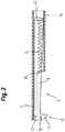
- the locking arrangement 6 comprises a force accumulator 9, which acts on the locking element 8 with a closing force, with the aid of which it can be moved from an open position, as shown in FIG FIG. 2 is shown in a locking position, as in FIG. 3 is shown, is movable.
- the open position is defined as the position in which an approach of the door 3 in a front portion 10 of the locking assembly 6 is possible, the locking element 8 is therefore not yet engaged with a corresponding retaining element 20 of the door 3.
- the locking position is defined as the position in which the locking element 8, For example, via the nose 11 shown in the figures, is engaged with the holding element 20 and thereby locks the door 3 relative to the body 4.
- the locking element 8 is in the open position ( FIG. 2 ), wherein it is preferably in contact with a stop surface 12, the early movement into the locking position ( FIG. 3 ) prevented.
- the locking element 8 preferably has a release element 13, which in the Figures 2 and 3 is exemplified as a laterally projecting bolt.
- the door 3 should expediently have a corresponding, for example wedge-shaped, counter element, which, upon contact with the release element 13, causes the front region 10 of the locking element 8 to move downward, so that it can slide over the stop surface 12.
- a release element 13 of course, another construction can be used, which causes the said movement of the locking element 8. It is also conceivable, for example, a rotary latch, which undergoes a rotation upon contact with the door 3, wherein this rotation finally results in a movement of the locking element 8, so that it is moved away from the stop surface 12.
- the energy accumulator 9 may in this case, for example, be formed as a spiral spring as shown, which is supported on the one hand in the region of a rear region 14 of the locking element 8 and on the other on a support surface 15 of the frame member 7. As a result, a force is exerted on the locking element 8, which pulls it in the direction of the rear region 14.
- the door 3 Since the locking element 8 is in its locking position with the retaining element 20 of the door 3 in engagement, the door 3 is also drawn to the body 4 and to a arranged between the body 4 and door 3 door seal, so that leakage of rinsing liquid and / or steam can be excluded.
- the frame member 1 can be equipped with corresponding guide surfaces which cooperate with corresponding mating surfaces of the locking element 8.
- the nose 11 and / or the holding member 20 a corresponding shape, as in FIG. 3 shown, which causes the said upward movement in contact with the door 3.
- FIG. 3 shows the locking assembly 6 with the door closed 3.
- the locking element 8 is thus in its locking position, so that the hook 11 of the locking element 8 is in engagement with the corresponding retaining element 20 in the door.
- the holding element 20 is designed as a recess - often referred to as a door recess 20 '- configured.
- Such a door well 20 ' is often in the form of an in FIG. 3 shown Mosmulden neighbores 21 used in the door 3 of the dishwasher 1.
- a sensor system which comprises at least one sensor 30 for detecting the movement of the locking element 8 or else a component operatively connected thereto.
- the sensor 30 can be designed as a resistive sensor, for example in the form of a strain gauge.
- a capacitive, inductive, optical or piezoelectric sensor A combination of several, even different sensors is conceivable. Exemplary are in FIG. 3 two alternative mounting locations for the sensor 30 with an x and the reference numerals 30-1 and 30-2 marked. A first installation location 30-1 lies in the area behind the locking element 8.
- the sensor 30 can then detect the movement of the locking element 8 caused by the force acting on the door 3 and thus the door trough insert 21 in the form of the approach of the locking element 8 to the sensor 30 , In addition to the direct detection of the movement of the locking element 8, it is also conceivable to detect the movement of a standing with the locking element 8 operatively connected component, such as the Mosmulden lymphes 21.
- An alternative second installation location 30-2 of the sensor 30 is therefore in the region of the door well insert 21. In addition to the two installation locations 30-1 and 30-2 illustrated, however, numerous other installation locations are conceivable.
- the selected type of sensor and the selected installation location ensure reliable detection of the movement of the locking element 8 or a component operatively connected thereto, it being noted that the movement is in the range of less than 1 millimeter, in particular less than 80 microns or even less than 50 microns.
- the component which is in operative connection with the locking element 8 can also be designed as an additional part or intermediate element, which is brought into operative connection exclusively with the locking element 8 for the purpose of indirectly detecting the movement of the locking element 8. In this way, if necessary, a higher flexibility with regard to the installation location for the sensor 30 can be achieved.
- the component can also comprise several subcomponents.
- the sensor system has a control unit 31 (cf. FIGS. 4 and 5 ), which compares the detected movement with a predeterminable threshold value and, when the limit value is exceeded, controls an actuator system in such a way that the door is unlocked and opens, at least in columns.
- the actuator system has an unlocking actuator as well as an opening actuator which can be realized separately from one another or at least with respect to subcomponents.
- An exemplary embodiment of a Entriegelungsaktuatorik 32 is in the FIGS. 4 and 5 shown.
- the Entriegelungsaktuatorik 32 has a drive unit 33, by means of which the locking element 8 is movable from the locking position against the closing force of the energy accumulator 9 in the open position.
- drive unit 33 is for this any drive in question, which allows a corresponding movement of the locking element 8 from the locking position to the open position.
- Conceivable for example, linear drives, electric drives, possibly also with gear, bimetals or similar responsive to temperature fluctuations components, etc.
- FIGS. 4 and 5 indicated a solution in which the drive unit 33 is formed by an electric drive 33 ', which is preferably connected independently of the frame member 7 with the body 4 of the dishwasher 1, so that at any time a corresponding retrofitting is possible.
- a connecting element 34 in the form of a rotary arm 34 ' is non-rotatably connected to a rotatable shaft 35 of the electric drive 33'.
- a driver 36 is rotatably mounted on the rotary arm 34 'spaced from the shaft 35.
- the axis of rotation of the driver 36 is preferably perpendicular to the plane defined by the width direction and depth direction of the body 4 level.
- the connecting element may also be otherwise, e.g. as a hub, be executed.
- the operative connection between drive unit 33 and locking element 8 is realized by means of an intermediate member 37, which is formed in the example shown as a rocker arm 37 ', which is rotatably supported via a rotation axis 38.
- the axis of rotation 38 of the rocker arm 37 ' is preferably perpendicular to the plane defined by the width direction and depth direction of the body 4, so that the rocker arm 37' sweeps over a pivoting range in this positional plane.
- a first leg 39 of the rocker arm 37' is guided in the driver 36, that is movably mounted in the driver 36 in the longitudinal direction of the first leg 39.
- the rotary arm 34 executes a rotational movement which, due to the bearing of the first leg 39 of the rocker arm 37' in the driver 36, results in a rotation of the rocker arm about the axis of rotation 38.
- the rocker arm 37 'of the in FIG. 4 position shown in a position as shown in FIG. 5 is shown, rotated.
- the illustrated embodiment is characterized according to the FIGS. 4 and 5 by a particularly space-saving arrangement, which in particular results from the fact that by the movement of the rotary arm 34 'spanned circle is fully utilized.
- the Entriegelungsaktuatorik 32 but also be designed differently. Examples also arise from the earlier application DE 10 2011 007 538.0 ,
- the opening actuation necessary for the actual opening of the door 3 can be largely or completely independent of the unlocking actuator 32, for example in the form of be realized one or more spring elements, which are arranged for example in the region of the hinge 5.
- the ⁇ réellesaktuatorik can also, for example, as an impact element, for example in the form of a plunger, which acts on the door, be realized. It is advantageous to share at least individual components of the Entriegelungsaktuatorik 32, such as the drive unit 33 for the ⁇ Stammsaktuatorik.
- the opening of the door 3 can be done in columns, completely or in any insectslposition.
- the sensor 30 for detecting the movement of the locking element 8 can also in the in the FIGS. 4 and 5 illustrated embodiment may be arranged at different installation locations. Exemplary are in FIG. 4 again two conceivable installation locations 30-3 and 30-4 marked by an x.
- a first installation location 30-3 lies in the region between the contact surface 42 in the rear region 14 of the locking element 8 and the engagement surface 40 of the second leg 41 of the rocker arm 37 '.
- the installation site thus corresponds to the installation location 30-1 according to FIG. 3 so that the sensor 30 can detect the movement of the locking element 8 caused by pressing on the door in the form of the approach of the locking element 8 to the sensor 30.
- An alternative second installation location 30-4 of the sensor 30 lies in the region behind the second leg 41 of the rocker arm 37 ', which is in operative connection with the locking element, so that its movement is also suitable for sensing an opening desire.
- the sensor system comprises a control unit 31, which in FIG. 4 is indicated schematically.
- the control unit 31 compares the movement detected by the sensor 30 with a predefinable threshold value and, when the limit value is exceeded, actuates the actuator system, that is to say the unlocking and opening actuators, in such a way that the door is unlocked and opened at least in columns.
- the threshold value is preferably determined as a function of operating parameters and / or ambient conditions of the dishwasher in order to take into account the respective current operating situation.
- the Entriegelungsaktuatorik 32 can be arranged together with the sensor system, that is, the sensor 30 and the control unit 31 on a common support member 46, for example in the form of a housing, so that it can be installed as a complete module and in particular also retrofitted.
- FIG. 5 shows next to the locking assembly 6 and the Entriegelungsaktuatorik 32 also a possible positioning of the same.
- the frame element 7 on the upper side of the already mentioned body 4 of the dishwasher 1, wherein this may have an opening 47 in its region facing the door 3, through which a part of the locking element 8, for. B. the nose 11, at least in the locking position can protrude to engage with the corresponding holding element 20, for example in the form of the door recess 20 'in engagement.
- the door 3 in FIG. 5 still a gap is opened. In order to activate the closing mechanism, it would thus have to be moved further in the direction of the body 4 until the holding element 20 is located under the nose 11 of the locking element 8.
- a decorative plate 48 On the outer wall 3-2 of in FIG. 5 shown door 3 is a decorative plate 48, which may be designed in particular handleless, gap-free and fixed relative to the outer wall 3-2 immovably.
- the decorative plate 48 can cover the outer wall 3-2 of the door over the entire surface.
- the locking assembly 6 is respectively attached to the body 4 of the dishwasher and cooperates with a arranged on the door 3 corresponding holding element 20 together.
- the locking assembly 6 but also be attached to the door 3 and accordingly cooperate with a holding element 3, which is arranged on the body 4 and which is embodied for example in the form of a rotary latch, which in a force on the door 3 in the direction of Rinse container undergoes a rotation. This rotational movement can then be detected in turn depending on the door 3 unlocked and opened.
Landscapes
- Washing And Drying Of Tableware (AREA)
Claims (10)
- Lave-vaisselle (1), notamment lave-vaisselle à usage domestique, comprenant- une cuve de lavage (2) destinée à réceptionner des produits à nettoyer,- une porte (3) pivotante, notamment sans poignée, laquelle, en position fermée, ferme la cuve de lavage (2),- un agencement de verrouillage (6) au moyen duquel la porte (3), dans sa position fermée, peut être verrouillée et lequel comprend au moins un élément de verrouillage (8) logé de manière déplaçable,- un système de capteurs destiné à détecter un mouvement de l'au moins un élément de verrouillage (8) logé de manière déplaçable ou un composant qui y est en liaison active, le mouvement étant causé par une force agissant sur la porte (3) fermée en direction de la cuve de lavage (2), le système de capteurs comprenant une unité de commande (31) qui compare le mouvement détecté avec une valeur seuil prédéfinissable et, lorsque la valeur seuil est dépassée, commande un système actionneur de manière à ce que la porte (3) soit déverrouillée et s'ouvre au moins en partie.
- Lave-vaisselle selon la revendication 1, caractérisé en ce qu'une plaque de décoration (48), notamment sans poignée, est fixée sur une paroi extérieure (3 - 2) de la porte (3), détournée de la cuve de lavage (2) en position fermée.
- Lave-vaisselle selon la revendication 2, caractérisé en ce que la plaque de décoration (48) est fixée sans écart sur la paroi extérieure (3 - 2) de la porte (3).
- Lave-vaisselle selon l'une quelconque des revendications 2 ou 3, caractérisé en ce que la plaque de décoration (48), par rapport à la paroi extérieure (3 - 2), est fixée de manière non déplaçable sur la paroi extérieure (3 - 2) de la porte (3).
- Lave-vaisselle selon l'une quelconque des revendications 2 à 4, caractérisé en ce que la plaque de décoration (48) recouvre la paroi extérieure (3 - 2) de la porte (3) sur toute la surface.
- Lave-vaisselle selon l'une quelconque des revendications précédentes, caractérisé en ce que le système actionneur comprend un système actionneur de déverrouillage (32) destiné à déverrouiller la porte (3) et en ce qu'un élément de support (46) est ménagé sur lequel sont disposés le système actionneur de déverrouillage (32) et au moins des parties du système de capteurs, notamment le système de capteurs tout entier.
- Lave-vaisselle selon l'une quelconque des revendications précédentes, caractérisé en ce que le système de capteurs présente au moins un capteur (30) résistif ou capacitif ou inductif ou optique ou piézoélectrique.
- Lave-vaisselle selon l'une quelconque des revendications précédentes, caractérisé en ce que la valeur seuil est variable en fonction de paramètres de fonctionnement et/ou de conditions ambiantes du lave-vaisselle.
- Procédé d'ouverture d'une porte (3) d'un lave-vaisselle (1), notamment d'un lave-vaisselle à usage domestique, comprenant- une cuve de lavage (2) destinée à réceptionner des produits à nettoyer,- la porte (3) pivotante, notamment sans poignée, laquelle, en position fermée, ferme la cuve de lavage (2),- un agencement de verrouillage (6) au moyen duquel la porte (3), dans sa position fermée, peut être verrouillée et lequel comprend au moins un élément de verrouillage (8) logé de manière déplaçable,dans lequel- un mouvement de l'au moins un élément de verrouillage (8) logé de manière déplaçable ou d'un composant qui y est en liaison active est détecté au moyen d'un système de capteurs, le mouvement étant causé par une force agissant sur la porte (3) fermée en direction de la cuve de lavage (2), et dans lequel- le mouvement détecté est comparé, par une unité de commande (31) du système de capteurs, avec une valeur seuil prédéfinissable- et dans lequel, lorsque la valeur seuil est dépassée, la porte (3) est déverrouillée et ouverte au moins en partie.
- Procédé selon la revendication 9, caractérisé en ce que la valeur seuil est déterminée en fonction de paramètres de fonctionnement et/ou de conditions ambiantes du lave-vaisselle (1).
Priority Applications (1)
| Application Number | Priority Date | Filing Date | Title |
|---|---|---|---|
| PL12731496T PL2734100T3 (pl) | 2011-07-21 | 2012-07-06 | Zmywarka do naczyń i sposób otwierania drzwi zmywarki do naczyń |
Applications Claiming Priority (2)
| Application Number | Priority Date | Filing Date | Title |
|---|---|---|---|
| DE102011079534A DE102011079534A1 (de) | 2011-07-21 | 2011-07-21 | Geschirrspülmaschine und Verfahren zum Öffnen einer Tür einer Geschirrspülmaschine |
| PCT/EP2012/063258 WO2013010819A1 (fr) | 2011-07-21 | 2012-07-06 | Lave-vaisselle et procédé d'ouverture d'une porte de lave-vaisselle |
Publications (2)
| Publication Number | Publication Date |
|---|---|
| EP2734100A1 EP2734100A1 (fr) | 2014-05-28 |
| EP2734100B1 true EP2734100B1 (fr) | 2019-03-06 |
Family
ID=46456637
Family Applications (1)
| Application Number | Title | Priority Date | Filing Date |
|---|---|---|---|
| EP12731496.1A Active EP2734100B1 (fr) | 2011-07-21 | 2012-07-06 | Lave-vaisselle et procédé d'ouverture d'une porte de lave-vaisselle |
Country Status (5)
| Country | Link |
|---|---|
| EP (1) | EP2734100B1 (fr) |
| DE (1) | DE102011079534A1 (fr) |
| PL (1) | PL2734100T3 (fr) |
| TR (1) | TR201904136T4 (fr) |
| WO (1) | WO2013010819A1 (fr) |
Families Citing this family (4)
| Publication number | Priority date | Publication date | Assignee | Title |
|---|---|---|---|---|
| DE102015212969B4 (de) | 2015-07-10 | 2019-04-18 | Koenig & Bauer Ag | UV-Bestrahlungsvorrichtung |
| DE102016205367A1 (de) * | 2016-03-31 | 2017-10-05 | Meiko Maschinenbau Gmbh & Co. Kg | Reinigungsvorrichtung und Verfahren zum Reinigen von Reinigungsgut |
| DE102019215312A1 (de) * | 2019-10-07 | 2021-04-08 | BSH Hausgeräte GmbH | Haushaltsgeschirrspülmaschine |
| DE102021207588A1 (de) * | 2021-07-16 | 2023-01-19 | BSH Hausgeräte GmbH | Haushaltsgeschirrspülmaschine |
Family Cites Families (10)
| Publication number | Priority date | Publication date | Assignee | Title |
|---|---|---|---|---|
| EP0772996B1 (fr) * | 1994-11-10 | 2001-10-10 | Miele & Cie. GmbH & Co. | Appareil electro-ménager, en particulier lave-vaisselle |
| DE19960814A1 (de) * | 1999-12-16 | 2001-06-28 | Bsh Bosch Siemens Hausgeraete | Betätigungsvorrichtung für einen Türverschluß |
| DE102005028448B4 (de) * | 2005-06-17 | 2007-09-27 | Miele & Cie. Kg | Geschirrspülmaschine |
| DE102005040990A1 (de) * | 2005-08-29 | 2007-03-01 | Miele & Cie. Kg | Geschirrspülmaschine |
| TR200504095A2 (tr) * | 2005-10-13 | 2007-10-22 | Bsh Ev Aletler� Sanay� Ve T�Caret Anon�M ��Rket�@ | Kapı açma yardımcı düzeneği. |
| DE102005062472A1 (de) * | 2005-12-27 | 2007-07-05 | BSH Bosch und Siemens Hausgeräte GmbH | Geschirrspülmaschine mit einem Selbstschließmechanismus zum Verriegeln der Tür und Verfahren zum Betreiben der Geschirrspülmaschine |
| PL1935313T3 (pl) | 2006-12-19 | 2010-04-30 | Bonferraro Spa | Wbudowane urządzenie gospodarstwa domowego z dekoracyjną płytą nałożoną na drzwiczki |
| DE102008021496B4 (de) * | 2008-04-29 | 2010-03-11 | Miele & Cie. Kg | Geschirrspülmaschine |
| DE102009026670A1 (de) * | 2009-06-03 | 2010-12-09 | BSH Bosch und Siemens Hausgeräte GmbH | Haushaltsgerät |
| DE102011007538A1 (de) | 2011-03-09 | 2012-09-13 | BSH Bosch und Siemens Hausgeräte GmbH | Verriegelungsanordnung zum Verriegeln einer Tür eines Haushaltsgeräts sowie Haushaltsgerät |
-
2011
- 2011-07-21 DE DE102011079534A patent/DE102011079534A1/de not_active Withdrawn
-
2012
- 2012-07-06 TR TR2019/04136T patent/TR201904136T4/tr unknown
- 2012-07-06 EP EP12731496.1A patent/EP2734100B1/fr active Active
- 2012-07-06 WO PCT/EP2012/063258 patent/WO2013010819A1/fr active Application Filing
- 2012-07-06 PL PL12731496T patent/PL2734100T3/pl unknown
Non-Patent Citations (1)
| Title |
|---|
| None * |
Also Published As
| Publication number | Publication date |
|---|---|
| DE102011079534A1 (de) | 2013-01-24 |
| PL2734100T3 (pl) | 2019-09-30 |
| WO2013010819A1 (fr) | 2013-01-24 |
| EP2734100A1 (fr) | 2014-05-28 |
| TR201904136T4 (tr) | 2019-04-22 |
Similar Documents
| Publication | Publication Date | Title |
|---|---|---|
| EP2280631B1 (fr) | Lave-vaisselle | |
| EP2280632B1 (fr) | Lave-vaisselle doté d'un dispositif destiné à entrouvrir la porte | |
| EP2753485B1 (fr) | Système de commande | |
| EP2497854B1 (fr) | Agencement de verrouillage d'une porte d'un appareil ménager ainsi qu'appareil ménager | |
| EP2845532B1 (fr) | Appareil ménager doté de mécanisme automatique d'ouverture de porte | |
| EP2470056B1 (fr) | Lave-vaisselle, notamment lave-vaisselle ménager, comportant une serrure de porte | |
| EP2166180B2 (fr) | Installation de fermeture | |
| EP2436864B1 (fr) | Fermeture de porte automatique pour appareil électroménager | |
| DE102007030655A1 (de) | Betätigungshandhabe für eine Tür | |
| EP2734100B1 (fr) | Lave-vaisselle et procédé d'ouverture d'une porte de lave-vaisselle | |
| EP2594713A2 (fr) | Ouverture de porte | |
| EP3022373A2 (fr) | Serrure de véhicule à dispositif de fermeture par traction ainsi que véhicule pourvu d'une serrure de ce type | |
| WO2017108889A1 (fr) | Dispositif de levage, procédé pour faire fonctionner un dispositif de levage et lave-vaisselle | |
| EP0361001B1 (fr) | Serrure à crochet | |
| DE102011015248B4 (de) | Verriegelungsvorrichtung | |
| DE102013016885A1 (de) | Fahrzeugtür und Türgriffeinheit für eine Fahrzeugtür | |
| DE102016101807A1 (de) | Haushaltsgerät mit einer bewegbaren Tür und Verfahren zum Bewegen einer Tür eines Haushaltsgeräts | |
| EP2166908B1 (fr) | Baignoire équipée d'une porte d'accès | |
| DE10303778B4 (de) | Betätigungsanordnung zum Öffnen und Schliessen eines Fahrzeugflügels | |
| WO2009000672A1 (fr) | Dispositif de verrouillage destiné à la porte d'un appareil électro-ménager, en particulier d'un lave-vaisselle et procédé permettant l'actionnement de la porte d'un appareil électroménager | |
| EP3324124B1 (fr) | Appareil de cuisson avec dispositif de verrouillage | |
| EP2952660B1 (fr) | Dispositif de fermeture assistée pour portes de véhicules automobiles | |
| EP3324125B1 (fr) | Appareil de cuisson avec un dispositif de verouillage | |
| EP1958539B1 (fr) | Armoire d'angle, en particulier armoire d'angle de cuisine | |
| EP2328454B1 (fr) | Lave-vaisselle à encastrer dans un placard |
Legal Events
| Date | Code | Title | Description |
|---|---|---|---|
| PUAI | Public reference made under article 153(3) epc to a published international application that has entered the european phase |
Free format text: ORIGINAL CODE: 0009012 |
|
| 17P | Request for examination filed |
Effective date: 20140221 |
|
| AK | Designated contracting states |
Kind code of ref document: A1 Designated state(s): AL AT BE BG CH CY CZ DE DK EE ES FI FR GB GR HR HU IE IS IT LI LT LU LV MC MK MT NL NO PL PT RO RS SE SI SK SM TR |
|
| DAX | Request for extension of the european patent (deleted) | ||
| RAP1 | Party data changed (applicant data changed or rights of an application transferred) |
Owner name: BSH HAUSGERAETE GMBH |
|
| GRAP | Despatch of communication of intention to grant a patent |
Free format text: ORIGINAL CODE: EPIDOSNIGR1 |
|
| STAA | Information on the status of an ep patent application or granted ep patent |
Free format text: STATUS: GRANT OF PATENT IS INTENDED |
|
| INTG | Intention to grant announced |
Effective date: 20181115 |
|
| GRAS | Grant fee paid |
Free format text: ORIGINAL CODE: EPIDOSNIGR3 |
|
| GRAA | (expected) grant |
Free format text: ORIGINAL CODE: 0009210 |
|
| STAA | Information on the status of an ep patent application or granted ep patent |
Free format text: STATUS: THE PATENT HAS BEEN GRANTED |
|
| AK | Designated contracting states |
Kind code of ref document: B1 Designated state(s): AL AT BE BG CH CY CZ DE DK EE ES FI FR GB GR HR HU IE IS IT LI LT LU LV MC MK MT NL NO PL PT RO RS SE SI SK SM TR |
|
| REG | Reference to a national code |
Ref country code: GB Ref legal event code: FG4D Free format text: NOT ENGLISH |
|
| REG | Reference to a national code |
Ref country code: CH Ref legal event code: EP Ref country code: AT Ref legal event code: REF Ref document number: 1103446 Country of ref document: AT Kind code of ref document: T Effective date: 20190315 |
|
| REG | Reference to a national code |
Ref country code: DE Ref legal event code: R096 Ref document number: 502012014393 Country of ref document: DE |
|
| REG | Reference to a national code |
Ref country code: IE Ref legal event code: FG4D Free format text: LANGUAGE OF EP DOCUMENT: GERMAN |
|
| REG | Reference to a national code |
Ref country code: NL Ref legal event code: MP Effective date: 20190306 |
|
| REG | Reference to a national code |
Ref country code: LT Ref legal event code: MG4D |
|
| PG25 | Lapsed in a contracting state [announced via postgrant information from national office to epo] |
Ref country code: SE Free format text: LAPSE BECAUSE OF FAILURE TO SUBMIT A TRANSLATION OF THE DESCRIPTION OR TO PAY THE FEE WITHIN THE PRESCRIBED TIME-LIMIT Effective date: 20190306 Ref country code: NO Free format text: LAPSE BECAUSE OF FAILURE TO SUBMIT A TRANSLATION OF THE DESCRIPTION OR TO PAY THE FEE WITHIN THE PRESCRIBED TIME-LIMIT Effective date: 20190606 Ref country code: FI Free format text: LAPSE BECAUSE OF FAILURE TO SUBMIT A TRANSLATION OF THE DESCRIPTION OR TO PAY THE FEE WITHIN THE PRESCRIBED TIME-LIMIT Effective date: 20190306 Ref country code: LT Free format text: LAPSE BECAUSE OF FAILURE TO SUBMIT A TRANSLATION OF THE DESCRIPTION OR TO PAY THE FEE WITHIN THE PRESCRIBED TIME-LIMIT Effective date: 20190306 |
|
| PG25 | Lapsed in a contracting state [announced via postgrant information from national office to epo] |
Ref country code: BG Free format text: LAPSE BECAUSE OF FAILURE TO SUBMIT A TRANSLATION OF THE DESCRIPTION OR TO PAY THE FEE WITHIN THE PRESCRIBED TIME-LIMIT Effective date: 20190606 Ref country code: GR Free format text: LAPSE BECAUSE OF FAILURE TO SUBMIT A TRANSLATION OF THE DESCRIPTION OR TO PAY THE FEE WITHIN THE PRESCRIBED TIME-LIMIT Effective date: 20190607 Ref country code: HR Free format text: LAPSE BECAUSE OF FAILURE TO SUBMIT A TRANSLATION OF THE DESCRIPTION OR TO PAY THE FEE WITHIN THE PRESCRIBED TIME-LIMIT Effective date: 20190306 Ref country code: LV Free format text: LAPSE BECAUSE OF FAILURE TO SUBMIT A TRANSLATION OF THE DESCRIPTION OR TO PAY THE FEE WITHIN THE PRESCRIBED TIME-LIMIT Effective date: 20190306 Ref country code: NL Free format text: LAPSE BECAUSE OF FAILURE TO SUBMIT A TRANSLATION OF THE DESCRIPTION OR TO PAY THE FEE WITHIN THE PRESCRIBED TIME-LIMIT Effective date: 20190306 Ref country code: RS Free format text: LAPSE BECAUSE OF FAILURE TO SUBMIT A TRANSLATION OF THE DESCRIPTION OR TO PAY THE FEE WITHIN THE PRESCRIBED TIME-LIMIT Effective date: 20190306 |
|
| PG25 | Lapsed in a contracting state [announced via postgrant information from national office to epo] |
Ref country code: RO Free format text: LAPSE BECAUSE OF FAILURE TO SUBMIT A TRANSLATION OF THE DESCRIPTION OR TO PAY THE FEE WITHIN THE PRESCRIBED TIME-LIMIT Effective date: 20190306 Ref country code: IT Free format text: LAPSE BECAUSE OF FAILURE TO SUBMIT A TRANSLATION OF THE DESCRIPTION OR TO PAY THE FEE WITHIN THE PRESCRIBED TIME-LIMIT Effective date: 20190306 Ref country code: ES Free format text: LAPSE BECAUSE OF FAILURE TO SUBMIT A TRANSLATION OF THE DESCRIPTION OR TO PAY THE FEE WITHIN THE PRESCRIBED TIME-LIMIT Effective date: 20190306 Ref country code: CZ Free format text: LAPSE BECAUSE OF FAILURE TO SUBMIT A TRANSLATION OF THE DESCRIPTION OR TO PAY THE FEE WITHIN THE PRESCRIBED TIME-LIMIT Effective date: 20190306 Ref country code: EE Free format text: LAPSE BECAUSE OF FAILURE TO SUBMIT A TRANSLATION OF THE DESCRIPTION OR TO PAY THE FEE WITHIN THE PRESCRIBED TIME-LIMIT Effective date: 20190306 Ref country code: AL Free format text: LAPSE BECAUSE OF FAILURE TO SUBMIT A TRANSLATION OF THE DESCRIPTION OR TO PAY THE FEE WITHIN THE PRESCRIBED TIME-LIMIT Effective date: 20190306 Ref country code: PT Free format text: LAPSE BECAUSE OF FAILURE TO SUBMIT A TRANSLATION OF THE DESCRIPTION OR TO PAY THE FEE WITHIN THE PRESCRIBED TIME-LIMIT Effective date: 20190706 Ref country code: SK Free format text: LAPSE BECAUSE OF FAILURE TO SUBMIT A TRANSLATION OF THE DESCRIPTION OR TO PAY THE FEE WITHIN THE PRESCRIBED TIME-LIMIT Effective date: 20190306 |
|
| PG25 | Lapsed in a contracting state [announced via postgrant information from national office to epo] |
Ref country code: SM Free format text: LAPSE BECAUSE OF FAILURE TO SUBMIT A TRANSLATION OF THE DESCRIPTION OR TO PAY THE FEE WITHIN THE PRESCRIBED TIME-LIMIT Effective date: 20190306 |
|
| REG | Reference to a national code |
Ref country code: DE Ref legal event code: R097 Ref document number: 502012014393 Country of ref document: DE |
|
| PG25 | Lapsed in a contracting state [announced via postgrant information from national office to epo] |
Ref country code: IS Free format text: LAPSE BECAUSE OF FAILURE TO SUBMIT A TRANSLATION OF THE DESCRIPTION OR TO PAY THE FEE WITHIN THE PRESCRIBED TIME-LIMIT Effective date: 20190706 |
|
| PLBE | No opposition filed within time limit |
Free format text: ORIGINAL CODE: 0009261 |
|
| STAA | Information on the status of an ep patent application or granted ep patent |
Free format text: STATUS: NO OPPOSITION FILED WITHIN TIME LIMIT |
|
| PG25 | Lapsed in a contracting state [announced via postgrant information from national office to epo] |
Ref country code: DK Free format text: LAPSE BECAUSE OF FAILURE TO SUBMIT A TRANSLATION OF THE DESCRIPTION OR TO PAY THE FEE WITHIN THE PRESCRIBED TIME-LIMIT Effective date: 20190306 |
|
| 26N | No opposition filed |
Effective date: 20191209 |
|
| PG25 | Lapsed in a contracting state [announced via postgrant information from national office to epo] |
Ref country code: SI Free format text: LAPSE BECAUSE OF FAILURE TO SUBMIT A TRANSLATION OF THE DESCRIPTION OR TO PAY THE FEE WITHIN THE PRESCRIBED TIME-LIMIT Effective date: 20190306 Ref country code: MC Free format text: LAPSE BECAUSE OF FAILURE TO SUBMIT A TRANSLATION OF THE DESCRIPTION OR TO PAY THE FEE WITHIN THE PRESCRIBED TIME-LIMIT Effective date: 20190306 |
|
| REG | Reference to a national code |
Ref country code: CH Ref legal event code: PL |
|
| GBPC | Gb: european patent ceased through non-payment of renewal fee |
Effective date: 20190706 |
|
| REG | Reference to a national code |
Ref country code: BE Ref legal event code: MM Effective date: 20190731 |
|
| PG25 | Lapsed in a contracting state [announced via postgrant information from national office to epo] |
Ref country code: GB Free format text: LAPSE BECAUSE OF NON-PAYMENT OF DUE FEES Effective date: 20190706 |
|
| PG25 | Lapsed in a contracting state [announced via postgrant information from national office to epo] |
Ref country code: LI Free format text: LAPSE BECAUSE OF NON-PAYMENT OF DUE FEES Effective date: 20190731 Ref country code: CH Free format text: LAPSE BECAUSE OF NON-PAYMENT OF DUE FEES Effective date: 20190731 Ref country code: BE Free format text: LAPSE BECAUSE OF NON-PAYMENT OF DUE FEES Effective date: 20190731 Ref country code: LU Free format text: LAPSE BECAUSE OF NON-PAYMENT OF DUE FEES Effective date: 20190706 |
|
| PG25 | Lapsed in a contracting state [announced via postgrant information from national office to epo] |
Ref country code: FR Free format text: LAPSE BECAUSE OF NON-PAYMENT OF DUE FEES Effective date: 20190731 |
|
| PG25 | Lapsed in a contracting state [announced via postgrant information from national office to epo] |
Ref country code: IE Free format text: LAPSE BECAUSE OF NON-PAYMENT OF DUE FEES Effective date: 20190706 |
|
| REG | Reference to a national code |
Ref country code: AT Ref legal event code: MM01 Ref document number: 1103446 Country of ref document: AT Kind code of ref document: T Effective date: 20190706 |
|
| PG25 | Lapsed in a contracting state [announced via postgrant information from national office to epo] |
Ref country code: AT Free format text: LAPSE BECAUSE OF NON-PAYMENT OF DUE FEES Effective date: 20190706 |
|
| PG25 | Lapsed in a contracting state [announced via postgrant information from national office to epo] |
Ref country code: CY Free format text: LAPSE BECAUSE OF FAILURE TO SUBMIT A TRANSLATION OF THE DESCRIPTION OR TO PAY THE FEE WITHIN THE PRESCRIBED TIME-LIMIT Effective date: 20190306 |
|
| PG25 | Lapsed in a contracting state [announced via postgrant information from national office to epo] |
Ref country code: HU Free format text: LAPSE BECAUSE OF FAILURE TO SUBMIT A TRANSLATION OF THE DESCRIPTION OR TO PAY THE FEE WITHIN THE PRESCRIBED TIME-LIMIT; INVALID AB INITIO Effective date: 20120706 Ref country code: MT Free format text: LAPSE BECAUSE OF FAILURE TO SUBMIT A TRANSLATION OF THE DESCRIPTION OR TO PAY THE FEE WITHIN THE PRESCRIBED TIME-LIMIT Effective date: 20190306 |
|
| PG25 | Lapsed in a contracting state [announced via postgrant information from national office to epo] |
Ref country code: MK Free format text: LAPSE BECAUSE OF FAILURE TO SUBMIT A TRANSLATION OF THE DESCRIPTION OR TO PAY THE FEE WITHIN THE PRESCRIBED TIME-LIMIT Effective date: 20190306 |
|
| PGFP | Annual fee paid to national office [announced via postgrant information from national office to epo] |
Ref country code: PL Payment date: 20240625 Year of fee payment: 13 |
|
| PGFP | Annual fee paid to national office [announced via postgrant information from national office to epo] |
Ref country code: TR Payment date: 20240625 Year of fee payment: 13 |
|
| PGFP | Annual fee paid to national office [announced via postgrant information from national office to epo] |
Ref country code: DE Payment date: 20240731 Year of fee payment: 13 |