EP2733766A1 - Rechargeable battery - Google Patents
Rechargeable battery Download PDFInfo
- Publication number
- EP2733766A1 EP2733766A1 EP13170669.9A EP13170669A EP2733766A1 EP 2733766 A1 EP2733766 A1 EP 2733766A1 EP 13170669 A EP13170669 A EP 13170669A EP 2733766 A1 EP2733766 A1 EP 2733766A1
- Authority
- EP
- European Patent Office
- Prior art keywords
- terminal
- insulator
- plate
- cap plate
- recess
- Prior art date
- Legal status (The legal status is an assumption and is not a legal conclusion. Google has not performed a legal analysis and makes no representation as to the accuracy of the status listed.)
- Granted
Links
Images


Classifications
-
- H—ELECTRICITY
- H01—ELECTRIC ELEMENTS
- H01M—PROCESSES OR MEANS, e.g. BATTERIES, FOR THE DIRECT CONVERSION OF CHEMICAL ENERGY INTO ELECTRICAL ENERGY
- H01M50/00—Constructional details or processes of manufacture of the non-active parts of electrochemical cells other than fuel cells, e.g. hybrid cells
- H01M50/50—Current conducting connections for cells or batteries
- H01M50/571—Methods or arrangements for affording protection against corrosion; Selection of materials therefor
-
- H—ELECTRICITY
- H01—ELECTRIC ELEMENTS
- H01M—PROCESSES OR MEANS, e.g. BATTERIES, FOR THE DIRECT CONVERSION OF CHEMICAL ENERGY INTO ELECTRICAL ENERGY
- H01M10/00—Secondary cells; Manufacture thereof
- H01M10/04—Construction or manufacture in general
- H01M10/0413—Large-sized flat cells or batteries for motive or stationary systems with plate-like electrodes
-
- H—ELECTRICITY
- H01—ELECTRIC ELEMENTS
- H01M—PROCESSES OR MEANS, e.g. BATTERIES, FOR THE DIRECT CONVERSION OF CHEMICAL ENERGY INTO ELECTRICAL ENERGY
- H01M10/00—Secondary cells; Manufacture thereof
- H01M10/04—Construction or manufacture in general
- H01M10/0431—Cells with wound or folded electrodes
-
- H—ELECTRICITY
- H01—ELECTRIC ELEMENTS
- H01M—PROCESSES OR MEANS, e.g. BATTERIES, FOR THE DIRECT CONVERSION OF CHEMICAL ENERGY INTO ELECTRICAL ENERGY
- H01M50/00—Constructional details or processes of manufacture of the non-active parts of electrochemical cells other than fuel cells, e.g. hybrid cells
- H01M50/10—Primary casings; Jackets or wrappings
- H01M50/147—Lids or covers
-
- H—ELECTRICITY
- H01—ELECTRIC ELEMENTS
- H01M—PROCESSES OR MEANS, e.g. BATTERIES, FOR THE DIRECT CONVERSION OF CHEMICAL ENERGY INTO ELECTRICAL ENERGY
- H01M50/00—Constructional details or processes of manufacture of the non-active parts of electrochemical cells other than fuel cells, e.g. hybrid cells
- H01M50/10—Primary casings; Jackets or wrappings
- H01M50/147—Lids or covers
- H01M50/155—Lids or covers characterised by the material
-
- H—ELECTRICITY
- H01—ELECTRIC ELEMENTS
- H01M—PROCESSES OR MEANS, e.g. BATTERIES, FOR THE DIRECT CONVERSION OF CHEMICAL ENERGY INTO ELECTRICAL ENERGY
- H01M50/00—Constructional details or processes of manufacture of the non-active parts of electrochemical cells other than fuel cells, e.g. hybrid cells
- H01M50/10—Primary casings; Jackets or wrappings
- H01M50/147—Lids or covers
- H01M50/155—Lids or covers characterised by the material
- H01M50/157—Inorganic material
- H01M50/159—Metals
-
- H—ELECTRICITY
- H01—ELECTRIC ELEMENTS
- H01M—PROCESSES OR MEANS, e.g. BATTERIES, FOR THE DIRECT CONVERSION OF CHEMICAL ENERGY INTO ELECTRICAL ENERGY
- H01M50/00—Constructional details or processes of manufacture of the non-active parts of electrochemical cells other than fuel cells, e.g. hybrid cells
- H01M50/50—Current conducting connections for cells or batteries
- H01M50/543—Terminals
-
- H—ELECTRICITY
- H01—ELECTRIC ELEMENTS
- H01M—PROCESSES OR MEANS, e.g. BATTERIES, FOR THE DIRECT CONVERSION OF CHEMICAL ENERGY INTO ELECTRICAL ENERGY
- H01M50/00—Constructional details or processes of manufacture of the non-active parts of electrochemical cells other than fuel cells, e.g. hybrid cells
- H01M50/50—Current conducting connections for cells or batteries
- H01M50/543—Terminals
- H01M50/564—Terminals characterised by their manufacturing process
- H01M50/567—Terminals characterised by their manufacturing process by fixing means, e.g. screws, rivets or bolts
-
- H—ELECTRICITY
- H01—ELECTRIC ELEMENTS
- H01M—PROCESSES OR MEANS, e.g. BATTERIES, FOR THE DIRECT CONVERSION OF CHEMICAL ENERGY INTO ELECTRICAL ENERGY
- H01M2200/00—Safety devices for primary or secondary batteries
- H01M2200/30—Preventing polarity reversal
-
- H—ELECTRICITY
- H01—ELECTRIC ELEMENTS
- H01M—PROCESSES OR MEANS, e.g. BATTERIES, FOR THE DIRECT CONVERSION OF CHEMICAL ENERGY INTO ELECTRICAL ENERGY
- H01M50/00—Constructional details or processes of manufacture of the non-active parts of electrochemical cells other than fuel cells, e.g. hybrid cells
- H01M50/50—Current conducting connections for cells or batteries
- H01M50/543—Terminals
- H01M50/547—Terminals characterised by the disposition of the terminals on the cells
- H01M50/55—Terminals characterised by the disposition of the terminals on the cells on the same side of the cell
-
- Y—GENERAL TAGGING OF NEW TECHNOLOGICAL DEVELOPMENTS; GENERAL TAGGING OF CROSS-SECTIONAL TECHNOLOGIES SPANNING OVER SEVERAL SECTIONS OF THE IPC; TECHNICAL SUBJECTS COVERED BY FORMER USPC CROSS-REFERENCE ART COLLECTIONS [XRACs] AND DIGESTS
- Y02—TECHNOLOGIES OR APPLICATIONS FOR MITIGATION OR ADAPTATION AGAINST CLIMATE CHANGE
- Y02E—REDUCTION OF GREENHOUSE GAS [GHG] EMISSIONS, RELATED TO ENERGY GENERATION, TRANSMISSION OR DISTRIBUTION
- Y02E60/00—Enabling technologies; Technologies with a potential or indirect contribution to GHG emissions mitigation
- Y02E60/10—Energy storage using batteries
-
- Y—GENERAL TAGGING OF NEW TECHNOLOGICAL DEVELOPMENTS; GENERAL TAGGING OF CROSS-SECTIONAL TECHNOLOGIES SPANNING OVER SEVERAL SECTIONS OF THE IPC; TECHNICAL SUBJECTS COVERED BY FORMER USPC CROSS-REFERENCE ART COLLECTIONS [XRACs] AND DIGESTS
- Y02—TECHNOLOGIES OR APPLICATIONS FOR MITIGATION OR ADAPTATION AGAINST CLIMATE CHANGE
- Y02P—CLIMATE CHANGE MITIGATION TECHNOLOGIES IN THE PRODUCTION OR PROCESSING OF GOODS
- Y02P70/00—Climate change mitigation technologies in the production process for final industrial or consumer products
- Y02P70/50—Manufacturing or production processes characterised by the final manufactured product
Definitions
- the described technology relates generally to a rechargeable battery.
- a rechargeable battery is a battery configured to be repeatedly charged and discharged, which is different from a primary battery.
- Small capacity rechargeable batteries are often used in portable and small electronic devices, such as mobile phones, notebook computers, and camcorders.
- Large capacity rechargeable batteries may be used as a power source for driving a motor of a hybrid car or an electric car.
- Electrolyte fluids of rechargeable batteries may permeate into internal spaces that are intended to be isolated from the electrolyte fluid, due to limitations in the performance and design of internal sealing materials. As a result, an electrode terminal may be corroded.
- the described technology has been made in an effort to provide a rechargeable battery which prevents or reduces electrolyte fluid from permeating into a space between the electrode terminal and a cap plate from the outside.
- An exemplary embodiment provides a rechargeable battery, including: an electrode assembly configured to perform charging and discharging; a case enclosing the electrode assembly; a cap plate coupled to an opening of the case; an electrode terminal engaging a terminal hole of the cap plate; and an insulator between the cap plate and the electrode terminal, wherein the insulator comprises: a fluid receiving recess at a side of the electrode terminal to receive fluid, and an outlet extending through the insulator from the fluid receiving recess to discharge the received fluid.
- the fluid receiving recess may be formed adjacent to a periphery of the electrode terminal, and the outlet may include first and second outlets at opposing ends of the cap plate in a longitudinal direction of the cap plate.
- the electrode terminal may include: a rivet terminal in the terminal hole; and a plate terminal coupled to the rivet terminal and at an external surface of the cap plate, and the insulator may be between the plate terminal and the cap plate, and surround a periphery of the plate terminal.
- the fluid receiving recess may be around a periphery of the plate terminal.
- the plate terminal may include a first receiving recess in a surface facing the insulator, and the insulator may include a first wall in the first receiving recess.
- the cap plate may include a second receiving recess in a surface facing the insulator, and the insulator may include a second wall in the second receiving recess.
- the electrode terminal may include a cathode terminal and an anode terminal, the anode terminal may be electrically coupled to the cap plate, and the cathode terminal and the cap plate may further include an external short part therebetween.
- the external short part may include: a short protrusion extending from the plate terminal and facing a short hole at the cap plate; and a short member installed at the short hole while facing the short protrusion.
- the first receiving recess may include: a first recess adjacent to an outer side of a rivet terminal of the cathode terminal; and a second recess adjacent to the short protrusion.
- the first wall may include: a first part coupled to the first recess; and a second part coupled to the second recess.
- the second receiving recess and the second wall may be adjacent to the rivet terminal of the cathode terminal.
- the electrode terminal may include a cathode terminal and an anode terminal
- the insulator may include: a first insulator between the cathode terminal and the cap plate and surrounding a periphery of a plate terminal of the cathode terminal; and a second insulator between the anode terminal and the cap plate and surrounding a periphery of a plate terminal of the anode terminal.
- the fluid receiving recess may include: a first fluid receiving recess around a periphery of the plate terminal of the cathode terminal; and a second fluid receiving recess around a periphery of the plate terminal of the anode terminal.
- the first receiving recess may include: a first recess at the plate terminal of the cathode terminal facing the first insulator; and a second recess at the plate terminal of the anode terminal facing the second insulator.
- the first wall may include: a first part of the first insulator in the first recess; and a second part of the second insulator to be inserted in the second recess.
- the second receiving recess may include: athirdrecess in a surface of the cap plate facing the first insulator; and a fourth recess in a surface of the cap plate facing the second insulator.
- the second wall may include: a third part of the first insulator in the third recess; and a fourthpart formed of the second insulator to be inserted in the fourthrecess.
- the fluid receiving recess and the outlet are included in the insulator installed between the electrode terminal and the cap plate, so that the electrolyte fluid entering from the outside is induced in the fluid receiving recess and is discharged through the outlet, thereby achieving an effect of preventing or reducing the electrolyte fluid from permeating therein. Accordingly, it is possible to prevent or reduce the electrode terminal installed at the terminal hole of the cap plate from being corroded.
- FIG. 1 is a schematic perspective view of a rechargeable battery according to a first exemplary embodiment of the present invention.
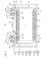
- FIG. 2 is a schematic cross-sectional view taken along line II-II of FIG. 1 .
- FIG. 3 is a schematic exploded perspective view of a cathode terminal side.
- FIG. 4 is a schematic cross-sectional view of a rechargeable battery according to a second exemplary embodiment of the present invention.
- a rechargeable battery includes an electrode assembly including electrodes at both surfaces of a separator, a case for accommodating the electrode assembly, and a cap plate coupled to an opening of the case, and an electrode terminal installed in the cap plate to be connected to the electrode through a lead tab.
- the electrode terminal includes a rivet terminal positioned in an inner side of the cap plate and a terminal hole to be electrically connected to the lead tab, and a plate terminal included outside the cap plate to be connected to the rivet terminal.
- a gasket is interposed between the rivet terminal and the terminal hole, and an insulator is interposed between the plate terminal and the cap plate, to seal a space between the electrode terminal and the terminal hole and electrically insulate the electrode terminal and the cap plate.
- FIG. 1 is a schematic perspective view of a rechargeable battery 100 according to a first exemplary embodiment of the present invention
- FIG. 2 is a schematic cross-sectional view taken along line II-II of FIG. 1 .
- the rechargeable battery 100 of the first exemplary embodiment includes an electrode assembly 30 for charging and discharging current, a case 35 surrounding (e.g., enclosing or accommodating) the electrode assembly 30, a cap plate 40 coupled to an opening of the case 35, a first electrode terminal 51 (hereinafter, referred to as a "cathode terminal") and a second electrode terminal 52 (hereinafter, referred to as an "anode terminal") installed in the cap plate 40, an external short part 60 included at a side of the cathode terminal 51, and an insulator 70 installed between the cathode terminal 51 and the cap plate 40.
- an electrode assembly 30 for charging and discharging current
- a case 35 surrounding (e.g., enclosing or accommodating) the electrode assembly 30
- a cap plate 40 coupled to an opening of the case 35
- a first electrode terminal 51 hereinafter, referred to as a "cathode terminal”
- a second electrode terminal 52 hereinafter, referred to as an "anode
- the electrode assembly 30 may be formed by positioning a first electrode 31 (hereinafter, referred to as a "cathode”) and a second electrode 32 (hereinafter, referred to as an "anode”) at opposing surfaces of the separator 33.
- the separator 33 is an insulating material.
- the cathode 31, the separator 33, and the anode 32 are wound or rolled together to form the electrode assembly 30.
- the cathode 31 and the anode 32 include coated portions 31a and 32a formed by coating or depositing an active material on a current collector of a metal plate, and uncoated or exposed portions 31b and 32b formed as a current collector on which the active material is not coated or deposited, respectively.
- the uncoated portion 31b of the cathode 31 is formed at one end of the cathode 31 along the wound cathode 31.
- the uncoated portion 32b of the anode 32 is formed at the other end of the anode 32 along the wound anode 32.
- the uncoated portions 31b and 32b are located at opposing ends of the electrode assembly 30, respectively.
- the case 35 is formed in an approximate cuboid so as to set a space for accommodating the electrode assembly 30 and an electrolyte solution therein, an opening for joining an outside space to an inside space is formed at one surface of the cuboid.
- the opening may permit the electrode assembly 30 to be inserted into the case 35.
- the cap plate 40 is installed at the opening of the case 35 to substantially seal the case 35.
- the case 35 and the cap plate 40 may be formed of aluminum, to facilitate welding of the case 35 to the cap plate 40.
- the cap plate 40 includes an electrolyte injection opening 49, a vent hole 44, and terminal holes H1 and H2.
- the electrolyte injection opening 49 permits the electrolyte solution to be injected into the case 35 after the cap plate 40 is coupled to the case 35. After injecting the electrolyte solution, the electrolyte injection opening 49 is sealed with a sealing stopper 47.
- the vent hole 44 is sealed with a vent plate 45 so as to discharge internal pressure of the rechargeable battery 100.
- the vent plate 45 is incised to open the vent hole 44.
- the vent plate 45 has a notch 45a for inducing the incision.
- the cathode terminal 51 and the anode terminal 52 are installed at the terminal holes H1 and H2 of the cap plate 40, and are electrically coupled to the electrode assembly 30. That is, the cathode terminal 51 is electrically coupled to the cathode 31 of the electrode assembly 30, and the anode terminal 52 is electrically coupled to the anode 32 of the electrode assembly 30. Accordingly, the electrode assembly 30 is coupled to the outside of the case 35 through the cathode terminal 51 and the anode terminal 52.
- the cathode terminal 51 and the anode terminal 52 are formed to have a similar structure or shape inside the cap plate 40, so that the same structure will be described together. However, the cathode terminal 51 and the anode terminal 52 are formed to have different structures or shapes outside the cap plate 40, so that the different structures will be separately described.
- the cathode and anode terminals 51 and 52 include rivet terminals 51a and 52a installed at or inserted into the terminal holes H1 and H2 of the cap plate 40, respectively.
- Flanges 51b and 52b are wider than rivet terminals 51a and 52a, respectively, and may be integrally formed with the respective rivet terminal 51a and 52a and enclosed by the cap plate 40 and the case 35.
- Plate terminals 51c and 52c are formed externally with respect to the case 35 and the cap plate 40, and may be coupled to the rivet terminals 51a and 52a by riveting or welding.
- Cathode and anode gaskets 36 and 37 are installed between the rivet terminals 51a and 52a of the cathode and anode terminals 51 and 52 and internal surfaces of the terminal holes H1 and H2 of the cap plate 40, respectively, to substantially seal and electrically insulate spaces between the rivet terminals 51a and 52a of the cathode and anode terminals 51 and 52 and the cap plate 40.
- the cathode and anode gaskets 36 and 37 further extend between the flanges 51b and 52b and the internal surface of the cap plate 40 to further seal and electrically insulate the spaces between the flanges 51b and 52b and the cap plate 40. That is, the cathode and anode gaskets 36 and 37 prevent or reduce the electrolyte solution from being leaked through the terminal holes H1 and H2 after installing the cathode and anode terminals 51 and 52 in the cap plate 40.
- Cathode and anode lead tabs 81 and 82 electrically couple the cathode and anode terminals 51 and 52 to the cathode and the anode 31 and 32 of the electrode assembly 30. That is, the cathode and anode lead tabs 81 and 82 are coupled to lower ends of the rivet terminals 51a and 52a while being supported by the flanges 51b and 52b by coupling the cathode and anode lead tabs 81 and 82 to the lower ends of the rivet terminals 51a and 52a and caulking the lower ends.
- Cathode and anode insulating members 83 and 84 are installed between the cathode and anode lead tabs 81 and 82 and the cap plate 40 to electrically insulate the cathode and anode lead tabs 81 and 82 and the cap plate 40.
- each of the cathode and anode insulating members 83 and 84 is coupled to the cap plate 40, and the other side of each of the cathode and anode insulating members 83 and 84 surrounds the cathode and anode lead tabs 81 and 82, the rivet terminals 51a and 52a, and the flanges 51b and 52b, to provide increased stability to a structure of the cathode and anode lead tabs 81, the rivet terminals 51a and 52a, and the flanges 51b and 52b.
- a top plate 52d will be described in relation to a plate terminal 52c of the anode terminal 52, and the external short part 60 will be described in relation to the plate terminal 52c of the cathode terminal 51.
- the top plate 52d in the anode terminal 52 electrically couples the plate terminal 52c and the cap plate 40.
- the top plate 52d is interposed between the plate terminal 52c and the cap plate 40, and permits a rivet terminal 52a to pass through.
- top plate 52d and the plate terminal 52c are coupled to an upper end of the rivet terminal 52a by coupling the top plate 52d and the plate terminal 52c to the upper end of the rivet terminal 52a and caulking the upper end.
- the plate terminal 52c is installed outside the cap plate 40 with the top plate 52d interposed therebetween.
- the anode gasket 37 further extends between the rivet terminal 52a and the top plate 52d. That is, the anode gasket 37 prevents the rivet terminal 52a and the top plate 52d from being directly electrically coupled to each other. That is, the top plate 52d is electrically coupled to the rivet terminal 52a through the plate terminal 52c.
- the anode terminal 52 is electrically coupled to the cap plate 40 to charge the cap plate 40 and the case 35 with the anode.
- the cathode terminal 51 is electrically insulated or isolated from the cap plate 40 by interposing the insulator 70 therebetween.
- FIG. 3 is an exploded perspective view of a side of the cathode terminal 51.
- the insulator 70 is located between the plate terminal 51a and the cap plate 40, and surrounds an outer side of the plate terminal 51c.
- the insulator 70 includes a fluid receiving recess 71 and an outlet 72.
- the fluid receiving recess 71 is adjacent to a side of the cathode terminal 51 so as to induce and receive electrolyte fluid, for example, moisture, entering from the outside.
- the outlet 72 is connected from the fluid receiving recess 71 to the outside to discharge the received fluid to the outside of the insulator 70.
- the fluid receiving recess 71 is formed adjacent to an outer circumference of the cathode terminal 51, and particularly, is formed at a border surrounding the outer side or along a periphery of the plate terminal 51c.
- the outlet 72 may be formed at both sides in a longitudinal direction of the cap plate 40 (left and right directions of FIG. 2 ).
- the cathode terminal 51 is electrically insulated from the cap plate 40 by the insulator 70, but may be electrically shorted with the cap plate 40 through the external short part 60.
- the cap plate 40 includes a short hole H3 under the cathode terminal 51, and the plate terminal 51c of the cathode terminal 51 is formed so as to extend in a direction of the short hole H3 away from the cap plate 40.
- the external short part 60 includes a short protrusion 61 and a short member 62 separated or shorted according to internal pressure.
- the short protrusion 61 is formed at the plate terminal 51c, so that the short protrusion 61 is separated or vertically offset with respect to the cap plate 40 by the insulator 70 and is therefore electrically insulated from the cap plate 40 by maintaining a state in which the short protrusion 61 is separated from the short member 62. Accordingly, the cap plate 40 maintains a state in which the cap plate 40 is electrically insulated from the cathode terminal 51.
- the short protrusion 61 downwardly protrudes toward the short hole H3 from the plate terminal 51c, and the short member 62 is installed or located at the short hole H3 to face the short protrusion 61. That is, the short protrusion 61 and the short member 62 correspond to the short hole H3, and face each other to maintain a separated state (a solid line state), and form a short state (an imaginary line state) by reversal of the short member 62 when internal pressure of the rechargeable battery 100 increases, so that current charged in the electrode assembly 30 may be discharged.
- a separated state a solid line state
- an imaginary line state an imaginary line state
- the plate terminal 51c of the cathode terminal 51 includes a first receiving recess G1 (e.g., first and second recesses G11 and G12) in a surface facing the insulator 70, and the insulator 70 includes a first wall B1 (e.g., first and second parts B11 and B12) protruding toward the first receiving recess G1 and to be inserted in the first receiving recess G1.
- first wall B1 e.g., first and second parts B11 and B12
- the cap plate 40 includes a second receiving recess G2 in a surface facing the insulator 70, and the insulator 70 includes a second wall B2 protruding toward the second receiving recess G2 to be inserted in the second receiving recess G2.
- the fluid receiving recess 71 induces and receives electrolyte fluid entering from the outside and discharges the electrolyte fluid through the outlet 72.
- the first and second receiving recesses G1 and G2 and the first and second walls B1 and B2 increase the distance or length of a permeation path of the electrolyte fluid in order to reduce the permeation of the electrolyte fluid.
- the first receiving recess G1 and the first wall B1 increase the distance or length of the permeation path in an upper surface of the insulator 70
- the second receiving recess G2 and the second wall B2 increase the distance or length of the permeation path in a lower surface of the insulator 70.
- the first receiving recess G1 includes a first recess G11 adjacent to an outer side of the rivet terminal 51a of the cathode terminal 51 and a second recess G12 adjacent to an outer side of the short protrusion 61.
- the first wall B1 includes a first part B11 protruding so as to be coupled to the first recess G11, and a second part B12 protruding so as to be coupled to the second recess G12.
- the first recess G11 and the first part B11 are coupled to each other to prevent or reduce the electrolyte fluid from permeating into the terminal hole H1.
- the second recess G12 and the second part B12 are coupled to each other to prevent or reduce the electrolyte fluid from permeating into the short hole H3.
- the second receiving recess G2 and the second wall B2 are adjacent to the outer side of the rivet terminal 51a of the cathode terminal 51. Accordingly, the second receiving recess G2 and the second wall B2 are coupled with each other to prevent or reduce the electrolyte fluid from permeating into the terminal hole H1.
- the terminal hole H1 at a side of the cathode terminal 51 forms a double electrolyte fluid blocking structure by the first recess G11 and the first part B11 in the upper surface of the insulator 70 and the second receiving recess G2 and the second wall B2 in the lower surface of the insulator 70. Accordingly, it is possible to more effectively prevent or reduce corrosion of the cathode terminal 51.
- FIG. 4 is a cross-sectional view of a rechargeable battery 200 according to the second exemplary embodiment of the present invention.
- a cathode terminal 251 and an anode terminal 252 are electrically insulated from the cap plate 240.
- an insulator 270 includes a first insulator 271 located between the cathode terminal 251 and the cap plate 240 and a second insulator 272 located between the anode terminal 252 and the cap plate 240.
- the first insulator 271 is located between a plate terminal 251c and the cap plate 240 at a side of the cathode terminal 251, and surrounds an outer side of the plate terminal 251c.
- the second insulator 272 is located between a plate terminal 252c and the cap plate 240 at a side of the anode terminal 252, and surrounds an outer side of the plate terminal 252c.
- a fluid receiving recess 91 includes first and second fluid receiving recesses 711 and 712 formed at borders or along a periphery of the first and second insulators 271 and 272 surrounding outer sides of the plate terminals 251c and 252c of the cathode and anode terminals 251 and 252, respectively.
- An outlet 92 includes first and second outlets 721 and 722 formed toward the outside at the first and second fluid receiving recesses 711 and 712, respectively, so as to discharge the fluid received in the fluid receiving recess 91 to the outside of the first and second insulators 271 and 272.
- the first receiving recess G21 includes first and second recesses G211 and G212 formed in a surface of the plate terminals 251c and 252c of the cathode and anode terminals 251 and 252 facing toward the first and second insulators 271 and 272.
- a first wall B21 includes first and second parts B211 and B212 formed in the first and second insulators 271 and 272 to be inserted in the first and second recesses G211 and G212.
- the second receiving recess G22 includes third and fourth h recesses G223 and G224 formed in a surface of the cap plate 240 facing toward the first and second insulators 271 and 272.
- the second wall B22 includes third and fourth parts B223 and B224 formed in the first and second insulators 271 and 272 in opposite sides of the first and second parts B211 and the B212 to be inserted in the third and fourth recesses G223 and G224.
- the coupling structures of the first and second parts B211 and B212 and the first and second recesses G211 and G212 block or reduce the electrolyte fluid from permeating from the outsides of the first and second insulators 271 and 272.
- the coupling structures of the third and fourth parts B223 and B224 and the third and fourth recesses G223 and G224 block or reduce the electrolyte fluid from permeating from the insides of the first and second insulators 271 and 272.
Landscapes
- Chemical & Material Sciences (AREA)
- Chemical Kinetics & Catalysis (AREA)
- Electrochemistry (AREA)
- General Chemical & Material Sciences (AREA)
- Engineering & Computer Science (AREA)
- Manufacturing & Machinery (AREA)
- Inorganic Chemistry (AREA)
- Connection Of Batteries Or Terminals (AREA)
Abstract
Description
- The described technology relates generally to a rechargeable battery.
- A rechargeable battery is a battery configured to be repeatedly charged and discharged, which is different from a primary battery. Small capacity rechargeable batteries are often used in portable and small electronic devices, such as mobile phones, notebook computers, and camcorders. Large capacity rechargeable batteries may be used as a power source for driving a motor of a hybrid car or an electric car.
- Electrolyte fluids of rechargeable batteries, however, may permeate into internal spaces that are intended to be isolated from the electrolyte fluid, due to limitations in the performance and design of internal sealing materials. As a result, an electrode terminal may be corroded.
- The described technology has been made in an effort to provide a rechargeable battery which prevents or reduces electrolyte fluid from permeating into a space between the electrode terminal and a cap plate from the outside.
- An exemplary embodiment provides a rechargeable battery, including: an electrode assembly configured to perform charging and discharging; a case enclosing the electrode assembly; a cap plate coupled to an opening of the case; an electrode terminal engaging a terminal hole of the cap plate; and an insulator between the cap plate and the electrode terminal, wherein the insulator comprises: a fluid receiving recess at a side of the electrode terminal to receive fluid, and an outlet extending through the insulator from the fluid receiving recess to discharge the received fluid.
- The fluid receiving recess may be formed adjacent to a periphery of the electrode terminal, and the outlet may include first and second outlets at opposing ends of the cap plate in a longitudinal direction of the cap plate.
- The electrode terminal may include: a rivet terminal in the terminal hole; and a plate terminal coupled to the rivet terminal and at an external surface of the cap plate, and the insulator may be between the plate terminal and the cap plate, and surround a periphery of the plate terminal.
- The fluid receiving recess may be around a periphery of the plate terminal.
- The plate terminal may include a first receiving recess in a surface facing the insulator, and the insulator may include a first wall in the first receiving recess.
- The cap plate may include a second receiving recess in a surface facing the insulator, and the insulator may include a second wall in the second receiving recess.
- The electrode terminal may include a cathode terminal and an anode terminal, the anode terminal may be electrically coupled to the cap plate, and the cathode terminal and the cap plate may further include an external short part therebetween.
- The external short part may include: a short protrusion extending from the plate terminal and facing a short hole at the cap plate; and a short member installed at the short hole while facing the short protrusion.
- The first receiving recess may include: a first recess adjacent to an outer side of a rivet terminal of the cathode terminal; and a second recess adjacent to the short protrusion.
- The first wall may include: a first part coupled to the first recess; and a second part coupled to the second recess.
- The second receiving recess and the second wall may be adjacent to the rivet terminal of the cathode terminal.
- The electrode terminal may include a cathode terminal and an anode terminal, and the insulator may include: a first insulator between the cathode terminal and the cap plate and surrounding a periphery of a plate terminal of the cathode terminal; and a second insulator between the anode terminal and the cap plate and surrounding a periphery of a plate terminal of the anode terminal.
- The fluid receiving recess may include: a first fluid receiving recess around a periphery of the plate terminal of the cathode terminal; and a second fluid receiving recess around a periphery of the plate terminal of the anode terminal.
- The first receiving recess may include: a first recess at the plate terminal of the cathode terminal facing the first insulator; and a second recess at the plate terminal of the anode terminal facing the second insulator.
- The first wall may include: a first part of the first insulator in the first recess; and a second part of the second insulator to be inserted in the second recess.
- The second receiving recess may include: athirdrecess in a surface of the cap plate facing the first insulator; and a fourth recess in a surface of the cap plate facing the second insulator.
- The second wall may include: a third part of the first insulator in the third recess; and a fourthpart formed of the second insulator to be inserted in the fourthrecess.
- According to the exemplary embodiment, the fluid receiving recess and the outlet are included in the insulator installed between the electrode terminal and the cap plate, so that the electrolyte fluid entering from the outside is induced in the fluid receiving recess and is discharged through the outlet, thereby achieving an effect of preventing or reducing the electrolyte fluid from permeating therein. Accordingly, it is possible to prevent or reduce the electrode terminal installed at the terminal hole of the cap plate from being corroded.
-
FIG. 1 is a schematic perspective view of a rechargeable battery according to a first exemplary embodiment of the present invention. -
FIG. 2 is a schematic cross-sectional view taken along line II-II ofFIG. 1 . -
FIG. 3 is a schematic exploded perspective view of a cathode terminal side. -
FIG. 4 is a schematic cross-sectional view of a rechargeable battery according to a second exemplary embodiment of the present invention. - A rechargeable battery includes an electrode assembly including electrodes at both surfaces of a separator, a case for accommodating the electrode assembly, and a cap plate coupled to an opening of the case, and an electrode terminal installed in the cap plate to be connected to the electrode through a lead tab.
- For example, the electrode terminal includes a rivet terminal positioned in an inner side of the cap plate and a terminal hole to be electrically connected to the lead tab, and a plate terminal included outside the cap plate to be connected to the rivet terminal.
- A gasket is interposed between the rivet terminal and the terminal hole, and an insulator is interposed between the plate terminal and the cap plate, to seal a space between the electrode terminal and the terminal hole and electrically insulate the electrode terminal and the cap plate.
-
FIG. 1 is a schematic perspective view of arechargeable battery 100 according to a first exemplary embodiment of the present invention, andFIG. 2 is a schematic cross-sectional view taken along line II-II ofFIG. 1 . - Referring to
FIGS. 1 and2 , therechargeable battery 100 of the first exemplary embodiment includes anelectrode assembly 30 for charging and discharging current, acase 35 surrounding (e.g., enclosing or accommodating) theelectrode assembly 30, acap plate 40 coupled to an opening of thecase 35, a first electrode terminal 51 (hereinafter, referred to as a "cathode terminal") and a second electrode terminal 52 (hereinafter, referred to as an "anode terminal") installed in thecap plate 40, an externalshort part 60 included at a side of thecathode terminal 51, and aninsulator 70 installed between thecathode terminal 51 and thecap plate 40. - For example, the
electrode assembly 30 may be formed by positioning a first electrode 31 (hereinafter, referred to as a "cathode") and a second electrode 32 (hereinafter, referred to as an "anode") at opposing surfaces of theseparator 33. Theseparator 33 is an insulating material. Thecathode 31, theseparator 33, and theanode 32 are wound or rolled together to form theelectrode assembly 30. - The
cathode 31 and theanode 32 include coatedportions portions - The
uncoated portion 31b of thecathode 31 is formed at one end of thecathode 31 along thewound cathode 31. Theuncoated portion 32b of theanode 32 is formed at the other end of theanode 32 along thewound anode 32. Theuncoated portions electrode assembly 30, respectively. - For example, the
case 35 is formed in an approximate cuboid so as to set a space for accommodating theelectrode assembly 30 and an electrolyte solution therein, an opening for joining an outside space to an inside space is formed at one surface of the cuboid. The opening may permit theelectrode assembly 30 to be inserted into thecase 35. - The
cap plate 40 is installed at the opening of thecase 35 to substantially seal thecase 35. Thecase 35 and thecap plate 40 may be formed of aluminum, to facilitate welding of thecase 35 to thecap plate 40. - Further, the
cap plate 40 includes an electrolyte injection opening 49, avent hole 44, and terminal holes H1 and H2. The electrolyte injection opening 49 permits the electrolyte solution to be injected into thecase 35 after thecap plate 40 is coupled to thecase 35. After injecting the electrolyte solution, the electrolyte injection opening 49 is sealed with asealing stopper 47. - The
vent hole 44 is sealed with avent plate 45 so as to discharge internal pressure of therechargeable battery 100. When the internal pressure of therechargeable battery 100 reaches predetermined pressure, thevent plate 45 is incised to open thevent hole 44. Thevent plate 45 has anotch 45a for inducing the incision. - The
cathode terminal 51 and theanode terminal 52 are installed at the terminal holes H1 and H2 of thecap plate 40, and are electrically coupled to theelectrode assembly 30. That is, thecathode terminal 51 is electrically coupled to thecathode 31 of theelectrode assembly 30, and theanode terminal 52 is electrically coupled to theanode 32 of theelectrode assembly 30. Accordingly, theelectrode assembly 30 is coupled to the outside of thecase 35 through thecathode terminal 51 and theanode terminal 52. - The
cathode terminal 51 and theanode terminal 52 are formed to have a similar structure or shape inside thecap plate 40, so that the same structure will be described together. However, thecathode terminal 51 and theanode terminal 52 are formed to have different structures or shapes outside thecap plate 40, so that the different structures will be separately described. - The cathode and
anode terminals rivet terminals cap plate 40, respectively.Flanges rivet terminals respective rivet terminal cap plate 40 and thecase 35.Plate terminals case 35 and thecap plate 40, and may be coupled to therivet terminals - Cathode and
anode gaskets rivet terminals anode terminals cap plate 40, respectively, to substantially seal and electrically insulate spaces between therivet terminals anode terminals cap plate 40. - The cathode and
anode gaskets flanges cap plate 40 to further seal and electrically insulate the spaces between theflanges cap plate 40. That is, the cathode andanode gaskets anode terminals cap plate 40. - Cathode and
anode lead tabs anode terminals anode electrode assembly 30. That is, the cathode andanode lead tabs rivet terminals flanges anode lead tabs rivet terminals - Cathode and anode insulating
members anode lead tabs cap plate 40 to electrically insulate the cathode andanode lead tabs cap plate 40. Further, one side of each of the cathode andanode insulating members cap plate 40, and the other side of each of the cathode andanode insulating members anode lead tabs rivet terminals flanges anode lead tabs 81, therivet terminals flanges - In the meantime, a
top plate 52d will be described in relation to aplate terminal 52c of theanode terminal 52, and the externalshort part 60 will be described in relation to theplate terminal 52c of thecathode terminal 51. - The
top plate 52d in theanode terminal 52 electrically couples theplate terminal 52c and thecap plate 40. For example, thetop plate 52d is interposed between theplate terminal 52c and thecap plate 40, and permits arivet terminal 52a to pass through. - Accordingly, the
top plate 52d and theplate terminal 52c are coupled to an upper end of therivet terminal 52a by coupling thetop plate 52d and theplate terminal 52c to the upper end of therivet terminal 52a and caulking the upper end. Theplate terminal 52c is installed outside thecap plate 40 with thetop plate 52d interposed therebetween. - The
anode gasket 37 further extends between therivet terminal 52a and thetop plate 52d. That is, theanode gasket 37 prevents therivet terminal 52a and thetop plate 52d from being directly electrically coupled to each other. That is, thetop plate 52d is electrically coupled to therivet terminal 52a through theplate terminal 52c. - As described above, the
anode terminal 52 is electrically coupled to thecap plate 40 to charge thecap plate 40 and thecase 35 with the anode. Thecathode terminal 51 is electrically insulated or isolated from thecap plate 40 by interposing theinsulator 70 therebetween. -
FIG. 3 is an exploded perspective view of a side of thecathode terminal 51. Referring toFIGS. 2 and3 , theinsulator 70 is located between theplate terminal 51a and thecap plate 40, and surrounds an outer side of theplate terminal 51c. Theinsulator 70 includes afluid receiving recess 71 and anoutlet 72. - The
fluid receiving recess 71 is adjacent to a side of thecathode terminal 51 so as to induce and receive electrolyte fluid, for example, moisture, entering from the outside. Theoutlet 72 is connected from thefluid receiving recess 71 to the outside to discharge the received fluid to the outside of theinsulator 70. - The
fluid receiving recess 71 is formed adjacent to an outer circumference of thecathode terminal 51, and particularly, is formed at a border surrounding the outer side or along a periphery of theplate terminal 51c. Theoutlet 72 may be formed at both sides in a longitudinal direction of the cap plate 40 (left and right directions ofFIG. 2 ). - The
cathode terminal 51 is electrically insulated from thecap plate 40 by theinsulator 70, but may be electrically shorted with thecap plate 40 through the externalshort part 60. - In order to form the external
short part 60, thecap plate 40 includes a short hole H3 under thecathode terminal 51, and theplate terminal 51c of thecathode terminal 51 is formed so as to extend in a direction of the short hole H3 away from thecap plate 40. - The external
short part 60 includes ashort protrusion 61 and ashort member 62 separated or shorted according to internal pressure. Theshort protrusion 61 is formed at theplate terminal 51c, so that theshort protrusion 61 is separated or vertically offset with respect to thecap plate 40 by theinsulator 70 and is therefore electrically insulated from thecap plate 40 by maintaining a state in which theshort protrusion 61 is separated from theshort member 62. Accordingly, thecap plate 40 maintains a state in which thecap plate 40 is electrically insulated from thecathode terminal 51. - For example, the
short protrusion 61 downwardly protrudes toward the short hole H3 from theplate terminal 51c, and theshort member 62 is installed or located at the short hole H3 to face theshort protrusion 61. That is, theshort protrusion 61 and theshort member 62 correspond to the short hole H3, and face each other to maintain a separated state (a solid line state), and form a short state (an imaginary line state) by reversal of theshort member 62 when internal pressure of therechargeable battery 100 increases, so that current charged in theelectrode assembly 30 may be discharged. - In the meantime, the
plate terminal 51c of thecathode terminal 51 includes a first receiving recess G1 (e.g., first and second recesses G11 and G12) in a surface facing theinsulator 70, and theinsulator 70 includes a first wall B1 (e.g., first and second parts B11 and B12) protruding toward the first receiving recess G1 and to be inserted in the first receiving recess G1. Please note that the "wall" could be called "protrusion" according to its shape shown inFig. 3 . Thecap plate 40 includes a second receiving recess G2 in a surface facing theinsulator 70, and theinsulator 70 includes a second wall B2 protruding toward the second receiving recess G2 to be inserted in the second receiving recess G2. - The
fluid receiving recess 71 induces and receives electrolyte fluid entering from the outside and discharges the electrolyte fluid through theoutlet 72. In comparison, the first and second receiving recesses G1 and G2 and the first and second walls B1 and B2 increase the distance or length of a permeation path of the electrolyte fluid in order to reduce the permeation of the electrolyte fluid. The first receiving recess G1 and the first wall B1 increase the distance or length of the permeation path in an upper surface of theinsulator 70, and the second receiving recess G2 and the second wall B2 increase the distance or length of the permeation path in a lower surface of theinsulator 70. - The first receiving recess G1 includes a first recess G11 adjacent to an outer side of the
rivet terminal 51a of thecathode terminal 51 and a second recess G12 adjacent to an outer side of theshort protrusion 61. The first wall B1 includes a first part B11 protruding so as to be coupled to the first recess G11, and a second part B12 protruding so as to be coupled to the second recess G12. - The first recess G11 and the first part B11 are coupled to each other to prevent or reduce the electrolyte fluid from permeating into the terminal hole H1. The second recess G12 and the second part B12 are coupled to each other to prevent or reduce the electrolyte fluid from permeating into the short hole H3.
- The second receiving recess G2 and the second wall B2 are adjacent to the outer side of the
rivet terminal 51a of thecathode terminal 51. Accordingly, the second receiving recess G2 and the second wall B2 are coupled with each other to prevent or reduce the electrolyte fluid from permeating into the terminal hole H1. - The terminal hole H1 at a side of the
cathode terminal 51 forms a double electrolyte fluid blocking structure by the first recess G11 and the first part B11 in the upper surface of theinsulator 70 and the second receiving recess G2 and the second wall B2 in the lower surface of theinsulator 70. Accordingly, it is possible to more effectively prevent or reduce corrosion of thecathode terminal 51. - Hereinafter, a second exemplary embodiment of the present invention will be described. A description of the same configuration as that of the first exemplary embodiment will be omitted, and a different configuration will be described.
-
FIG. 4 is a cross-sectional view of arechargeable battery 200 according to the second exemplary embodiment of the present invention. In therechargeable battery 200 of the second exemplary embodiment, acathode terminal 251 and ananode terminal 252 are electrically insulated from thecap plate 240. - To this end, an
insulator 270 includes afirst insulator 271 located between thecathode terminal 251 and thecap plate 240 and asecond insulator 272 located between theanode terminal 252 and thecap plate 240. - The
first insulator 271 is located between aplate terminal 251c and thecap plate 240 at a side of thecathode terminal 251, and surrounds an outer side of theplate terminal 251c. Thesecond insulator 272 is located between aplate terminal 252c and thecap plate 240 at a side of theanode terminal 252, and surrounds an outer side of theplate terminal 252c. - A
fluid receiving recess 91 includes first and secondfluid receiving recesses second insulators plate terminals anode terminals - An
outlet 92 includes first andsecond outlets fluid receiving recesses fluid receiving recess 91 to the outside of the first andsecond insulators - The first receiving recess G21 includes first and second recesses G211 and G212 formed in a surface of the
plate terminals anode terminals second insulators second insulators - The second receiving recess G22 includes third and fourth h recesses G223 and G224 formed in a surface of the
cap plate 240 facing toward the first andsecond insulators second insulators - The coupling structures of the first and second parts B211 and B212 and the first and second recesses G211 and G212 block or reduce the electrolyte fluid from permeating from the outsides of the first and
second insulators second insulators - It is clear for a person skilled in the art that the disclosed embodiments can also be combined where possible.
Claims (15)
- A rechargeable battery (100, 200), comprising:an electrode assembly (30) configured to perform charging and discharging;a case (35) enclosing the electrode assembly (30);a cap plate (40, 240) coupled to an opening of the case (35);an electrode terminal engaging a terminal hole (H1, H2) of the cap plate (40, 240); andan insulator (70, 270) between the cap plate (40, 240) and the electrode terminal,wherein the insulator (70, 270) comprises:a fluid receiving recess (71, 91) at a side of the electrode terminal to receive fluid, andan outlet (72, 92) extending through the insulator (70, 270) from the fluid receiving recess (71, 91) to discharge the received fluid.
- The rechargeable battery (100, 200) of claim 1, wherein:the fluid receiving recess (71, 91) is adjacent to a periphery of the electrode terminal
- The rechargeable battery (100, 200) of claim 1 or 2, wherein:the electrode terminal comprises:a rivet terminal (51a, 52a) in the terminal hole (H1, H2) ; anda plate terminal (51c, 52c,251c, 252c) coupled to the rivet terminal (51a, 52a) and at an external surface of the cap plate (40, 240), andthe insulator (70, 270) is between the plate terminal (51c, 52c,251c, 252c) and the cap plate (40, 240), and surrounds a periphery of the plate terminal (51c, 52c,251c, 252c).
- The rechargeable battery (100, 200) of one of claims 1 to 3, wherein:the fluid receiving recess (71, 91) is around a periphery of the plate terminal (51c, 52c,251c, 252c).
- The rechargeable battery (100, 200) of claim 3 or 4, wherein:the plate terminal (51c, 52c,251c, 252c) comprisesa first receiving recess (G1, G21) in a surface facing the insulator (70, 270), andthe insulator (70, 270) comprisesa first wall (B1, B21) in the first receiving recess (G1, G21).
- The rechargeable battery (100, 200) of one of claims 1 to 5, wherein:the cap plate (40, 240) comprisesa second receiving recess (G2, G22) in a surface facing the insulator (70, 270),
andthe insulator (70, 270) comprises a second wall (B2, B22) in the second receiving recess (G2, G22). - The rechargeable battery (100) of one of claims 1 to 6, wherein:the electrode terminal comprises a cathode terminal (51) and an anode terminal (52),the anode terminal (52) is electrically coupled to the cap plate (40), andthe cathode terminal (51) and the cap plate (40) further comprise an external short part (60) therebetween.
- The rechargeable battery (100) of claim 7, wherein:the external short part (60) comprises:a short protrusion (61) extending from the plate terminal (51c, 52c) and facing a short hole (H3) at the cap plate (40); anda short member (62) at the short hole (H3).
- The rechargeable battery (100) of one of claims 5 to 8, wherein:the first receiving recess (G1) comprises:a first recess (G11) adjacent to a rivet terminal (51a)of the cathode terminal (51);
anda second recess(G12) adjacent to the short protrusion (61). - The rechargeable battery (100) of one of claims 5 to 9, wherein:the first wall (B1) comprises:a first part (B11) coupled to the first recess (G11) ; anda second part (B12) coupled to the second recess (G12).
- The rechargeable battery (100) of one of claims 6 to10, wherein:the second receiving recess (G2) and the second wall (B2) are adjacent to the rivet terminal (51a) of the cathode terminal (51).
- The rechargeable battery (200) of one of claims 1 to 6, wherein:the electrode terminal comprises a cathode terminal (251) and an anode terminal (252), andthe insulator (270) comprises:a first insulator (271) between the cathode terminal (251) and the cap plate (240), and surrounding a periphery of a plate terminal (251c) of the cathode terminal (251); anda second insulator (272) between the anode terminal (252) and the cap plate (240), and surrounding a periphery of a plate terminal (252c) of the anode terminal (252).
- The rechargeable battery (200) of claim 12, wherein:the fluid receiving recess (91) comprises:a first fluid receiving recess (711) around a periphery of the plate terminal (251c) of the cathode terminal (251); anda second fluid receiving recess (712) around a periphery of the plate terminal (252c) of the anode terminal (252).
- The rechargeable battery of claim 12 or 13, wherein:the first receiving recess (G21) comprises:a first recess (G211) at a surface of the plate terminal (251c) of the cathode terminal (251) facing the first insulator (271);anda second recess (G212) at a surface of the plate terminal (252c) of the anode terminal (252) facing the second insulator (272) and/orthe second receiving recess (G22) comprises:a third recess (G223) in a surface of the cap plate(240) facing the first insulator (271); anda fourth recess (G224) in a surface of the cap plate (240) facing the second insulator (272).
- The rechargeable battery of one of claims 12 to 14, wherein:the first wall (B21) comprises:a first part (B211) of the first insulator (271) in the first recess (G211) ; anda second part (B212) of the second insulator(272) in the second recess (G212), and/or.the second wall (B22) comprises:a third part (B223) of the first insulator (271) in the third recess (G223) ; anda fourth part (B224) of the second insulator (272) in the fourth recess (G223).
Applications Claiming Priority (1)
| Application Number | Priority Date | Filing Date | Title |
|---|---|---|---|
| KR1020120131865A KR101683199B1 (en) | 2012-11-20 | 2012-11-20 | Rechargeable battery |
Publications (2)
| Publication Number | Publication Date |
|---|---|
| EP2733766A1 true EP2733766A1 (en) | 2014-05-21 |
| EP2733766B1 EP2733766B1 (en) | 2017-01-11 |
Family
ID=48537896
Family Applications (1)
| Application Number | Title | Priority Date | Filing Date |
|---|---|---|---|
| EP13170669.9A Active EP2733766B1 (en) | 2012-11-20 | 2013-06-05 | Rechargeable battery |
Country Status (4)
| Country | Link |
|---|---|
| US (1) | US9196892B2 (en) |
| EP (1) | EP2733766B1 (en) |
| KR (1) | KR101683199B1 (en) |
| CN (1) | CN103840120B (en) |
Families Citing this family (8)
| Publication number | Priority date | Publication date | Assignee | Title |
|---|---|---|---|---|
| KR102232532B1 (en) * | 2014-08-08 | 2021-03-25 | 삼성에스디아이 주식회사 | Rechargeable battery having short protrusion |
| JP2016105374A (en) * | 2014-12-01 | 2016-06-09 | トヨタ自動車株式会社 | Sealed battery |
| KR20160148316A (en) * | 2015-06-16 | 2016-12-26 | 삼성에스디아이 주식회사 | Rechargeable battery |
| KR102397857B1 (en) * | 2015-07-15 | 2022-05-12 | 삼성에스디아이 주식회사 | Rechargeable battery and rechargeable battery module using the same |
| KR102371192B1 (en) * | 2015-08-07 | 2022-03-07 | 삼성에스디아이 주식회사 | A secondary battery |
| JP6938923B2 (en) * | 2017-01-20 | 2021-09-22 | 株式会社Gsユアサ | Power storage element |
| CN111048934A (en) * | 2019-11-21 | 2020-04-21 | 歌尔股份有限公司 | Airflow sensor |
| CN117461193A (en) * | 2021-10-25 | 2024-01-26 | 宁德时代新能源科技股份有限公司 | End cap assembly, battery cell and preparation method thereof, battery and electrical device |
Citations (4)
| Publication number | Priority date | Publication date | Assignee | Title |
|---|---|---|---|---|
| US20100173190A1 (en) * | 2007-06-13 | 2010-07-08 | Kenji Tsuchiya | Battery cell and power supply |
| US20100279156A1 (en) * | 2009-07-09 | 2010-11-04 | Yong-Sam Kim | Rechargeable battery |
| EP2299512A1 (en) * | 2009-09-01 | 2011-03-23 | SB LiMotive Co., Ltd. | Cap assembly for a rechargeable battery |
| EP2490282A1 (en) * | 2011-02-18 | 2012-08-22 | SB LiMotive Co., Ltd. | Secondary battery |
Family Cites Families (7)
| Publication number | Priority date | Publication date | Assignee | Title |
|---|---|---|---|---|
| KR100436714B1 (en) * | 2002-10-29 | 2004-06-22 | 삼성에스디아이 주식회사 | Prismatic type lithium secondary battery |
| KR100599709B1 (en) * | 2004-07-28 | 2006-07-12 | 삼성에스디아이 주식회사 | Secondary battery |
| KR101264425B1 (en) | 2006-07-24 | 2013-05-14 | 삼성에스디아이 주식회사 | Cap assembly and rechargeable battery using the same |
| KR101126809B1 (en) | 2010-06-16 | 2012-03-23 | 에스비리모티브 주식회사 | Secondary Battery |
| KR101084056B1 (en) | 2010-07-21 | 2011-11-16 | 에스비리모티브 주식회사 | Secondary battery |
| US9293756B2 (en) * | 2010-09-17 | 2016-03-22 | Samsung Sdi Co., Ltd. | Rechargeable battery |
| JP2012134107A (en) | 2010-12-24 | 2012-07-12 | Fdk Twicell Co Ltd | Battery |
-
2012
- 2012-11-20 KR KR1020120131865A patent/KR101683199B1/en active Active
-
2013
- 2013-04-16 US US13/864,163 patent/US9196892B2/en active Active
- 2013-06-05 EP EP13170669.9A patent/EP2733766B1/en active Active
- 2013-11-04 CN CN201310537840.7A patent/CN103840120B/en active Active
Patent Citations (4)
| Publication number | Priority date | Publication date | Assignee | Title |
|---|---|---|---|---|
| US20100173190A1 (en) * | 2007-06-13 | 2010-07-08 | Kenji Tsuchiya | Battery cell and power supply |
| US20100279156A1 (en) * | 2009-07-09 | 2010-11-04 | Yong-Sam Kim | Rechargeable battery |
| EP2299512A1 (en) * | 2009-09-01 | 2011-03-23 | SB LiMotive Co., Ltd. | Cap assembly for a rechargeable battery |
| EP2490282A1 (en) * | 2011-02-18 | 2012-08-22 | SB LiMotive Co., Ltd. | Secondary battery |
Also Published As
| Publication number | Publication date |
|---|---|
| US20140141319A1 (en) | 2014-05-22 |
| CN103840120A (en) | 2014-06-04 |
| CN103840120B (en) | 2017-06-16 |
| US9196892B2 (en) | 2015-11-24 |
| EP2733766B1 (en) | 2017-01-11 |
| KR20140064474A (en) | 2014-05-28 |
| KR101683199B1 (en) | 2016-12-06 |
Similar Documents
| Publication | Publication Date | Title |
|---|---|---|
| EP2733766B1 (en) | Rechargeable battery | |
| KR102467002B1 (en) | Rechargeable battery | |
| KR102273643B1 (en) | Rechargeable battery | |
| KR102299244B1 (en) | Rechargeable battery and pack of the same | |
| KR102335021B1 (en) | Rechargeable battery and module of the same | |
| KR101084056B1 (en) | Secondary battery | |
| US11482757B2 (en) | Rechargeable battery | |
| KR102332446B1 (en) | Rechargeable battery and pack of the same | |
| EP2677563B1 (en) | Rechargeable battery and module of the same | |
| US20100233528A1 (en) | Rechargeable battery | |
| US20140322566A1 (en) | Rechargeable battery pack including pack cover | |
| KR102211527B1 (en) | Rechargeable battery | |
| US9252403B2 (en) | Rechargeable battery | |
| US9799874B2 (en) | Rechargeable battery | |
| KR102221633B1 (en) | Rechargeable battery | |
| EP2642561A1 (en) | Rechargeable battery | |
| KR101693292B1 (en) | Rechargeable battery | |
| US20150017496A1 (en) | Rechargeable battery pack | |
| US9692037B2 (en) | Rechargeable battery | |
| KR20170024417A (en) | Rechargeable battery | |
| KR102264702B1 (en) | Rechargeable battery | |
| KR102299243B1 (en) | Rechargeable battery | |
| KR102249891B1 (en) | Rechargeable battery module | |
| KR102611656B1 (en) | Secondary battery | |
| KR102531183B1 (en) | Rechargeable battery module |
Legal Events
| Date | Code | Title | Description |
|---|---|---|---|
| PUAI | Public reference made under article 153(3) epc to a published international application that has entered the european phase |
Free format text: ORIGINAL CODE: 0009012 |
|
| 17P | Request for examination filed |
Effective date: 20130605 |
|
| AK | Designated contracting states |
Kind code of ref document: A1 Designated state(s): AL AT BE BG CH CY CZ DE DK EE ES FI FR GB GR HR HU IE IS IT LI LT LU LV MC MK MT NL NO PL PT RO RS SE SI SK SM TR |
|
| AX | Request for extension of the european patent |
Extension state: BA ME |
|
| R17P | Request for examination filed (corrected) |
Effective date: 20141118 |
|
| RBV | Designated contracting states (corrected) |
Designated state(s): AL AT BE BG CH CY CZ DE DK EE ES FI FR GB GR HR HU IE IS IT LI LT LU LV MC MK MT NL NO PL PT RO RS SE SI SK SM TR |
|
| 17Q | First examination report despatched |
Effective date: 20160324 |
|
| RIC1 | Information provided on ipc code assigned before grant |
Ipc: H01M 2/04 20060101AFI20160804BHEP Ipc: H01M 2/32 20060101ALI20160804BHEP Ipc: H01M 10/04 20060101ALI20160804BHEP Ipc: H01M 2/30 20060101ALI20160804BHEP |
|
| GRAP | Despatch of communication of intention to grant a patent |
Free format text: ORIGINAL CODE: EPIDOSNIGR1 |
|
| INTG | Intention to grant announced |
Effective date: 20160921 |
|
| GRAS | Grant fee paid |
Free format text: ORIGINAL CODE: EPIDOSNIGR3 |
|
| STAA | Information on the status of an ep patent application or granted ep patent |
Free format text: STATUS: GRANT OF PATENT IS INTENDED |
|
| GRAA | (expected) grant |
Free format text: ORIGINAL CODE: 0009210 |
|
| STAA | Information on the status of an ep patent application or granted ep patent |
Free format text: STATUS: THE PATENT HAS BEEN GRANTED |
|
| AK | Designated contracting states |
Kind code of ref document: B1 Designated state(s): AL AT BE BG CH CY CZ DE DK EE ES FI FR GB GR HR HU IE IS IT LI LT LU LV MC MK MT NL NO PL PT RO RS SE SI SK SM TR |
|
| REG | Reference to a national code |
Ref country code: GB Ref legal event code: FG4D |
|
| REG | Reference to a national code |
Ref country code: CH Ref legal event code: EP |
|
| REG | Reference to a national code |
Ref country code: AT Ref legal event code: REF Ref document number: 861999 Country of ref document: AT Kind code of ref document: T Effective date: 20170115 |
|
| REG | Reference to a national code |
Ref country code: IE Ref legal event code: FG4D |
|
| REG | Reference to a national code |
Ref country code: DE Ref legal event code: R096 Ref document number: 602013016377 Country of ref document: DE |
|
| REG | Reference to a national code |
Ref country code: LT Ref legal event code: MG4D |
|
| REG | Reference to a national code |
Ref country code: NL Ref legal event code: MP Effective date: 20170111 |
|
| REG | Reference to a national code |
Ref country code: FR Ref legal event code: PLFP Year of fee payment: 5 |
|
| REG | Reference to a national code |
Ref country code: AT Ref legal event code: MK05 Ref document number: 861999 Country of ref document: AT Kind code of ref document: T Effective date: 20170111 |
|
| PG25 | Lapsed in a contracting state [announced via postgrant information from national office to epo] |
Ref country code: NL Free format text: LAPSE BECAUSE OF FAILURE TO SUBMIT A TRANSLATION OF THE DESCRIPTION OR TO PAY THE FEE WITHIN THE PRESCRIBED TIME-LIMIT Effective date: 20170111 |
|
| PG25 | Lapsed in a contracting state [announced via postgrant information from national office to epo] |
Ref country code: GR Free format text: LAPSE BECAUSE OF FAILURE TO SUBMIT A TRANSLATION OF THE DESCRIPTION OR TO PAY THE FEE WITHIN THE PRESCRIBED TIME-LIMIT Effective date: 20170412 Ref country code: LT Free format text: LAPSE BECAUSE OF FAILURE TO SUBMIT A TRANSLATION OF THE DESCRIPTION OR TO PAY THE FEE WITHIN THE PRESCRIBED TIME-LIMIT Effective date: 20170111 Ref country code: NO Free format text: LAPSE BECAUSE OF FAILURE TO SUBMIT A TRANSLATION OF THE DESCRIPTION OR TO PAY THE FEE WITHIN THE PRESCRIBED TIME-LIMIT Effective date: 20170411 Ref country code: FI Free format text: LAPSE BECAUSE OF FAILURE TO SUBMIT A TRANSLATION OF THE DESCRIPTION OR TO PAY THE FEE WITHIN THE PRESCRIBED TIME-LIMIT Effective date: 20170111 Ref country code: HR Free format text: LAPSE BECAUSE OF FAILURE TO SUBMIT A TRANSLATION OF THE DESCRIPTION OR TO PAY THE FEE WITHIN THE PRESCRIBED TIME-LIMIT Effective date: 20170111 Ref country code: IS Free format text: LAPSE BECAUSE OF FAILURE TO SUBMIT A TRANSLATION OF THE DESCRIPTION OR TO PAY THE FEE WITHIN THE PRESCRIBED TIME-LIMIT Effective date: 20170511 |
|
| PG25 | Lapsed in a contracting state [announced via postgrant information from national office to epo] |
Ref country code: PL Free format text: LAPSE BECAUSE OF FAILURE TO SUBMIT A TRANSLATION OF THE DESCRIPTION OR TO PAY THE FEE WITHIN THE PRESCRIBED TIME-LIMIT Effective date: 20170111 Ref country code: AT Free format text: LAPSE BECAUSE OF FAILURE TO SUBMIT A TRANSLATION OF THE DESCRIPTION OR TO PAY THE FEE WITHIN THE PRESCRIBED TIME-LIMIT Effective date: 20170111 Ref country code: PT Free format text: LAPSE BECAUSE OF FAILURE TO SUBMIT A TRANSLATION OF THE DESCRIPTION OR TO PAY THE FEE WITHIN THE PRESCRIBED TIME-LIMIT Effective date: 20170511 Ref country code: RS Free format text: LAPSE BECAUSE OF FAILURE TO SUBMIT A TRANSLATION OF THE DESCRIPTION OR TO PAY THE FEE WITHIN THE PRESCRIBED TIME-LIMIT Effective date: 20170111 Ref country code: ES Free format text: LAPSE BECAUSE OF FAILURE TO SUBMIT A TRANSLATION OF THE DESCRIPTION OR TO PAY THE FEE WITHIN THE PRESCRIBED TIME-LIMIT Effective date: 20170111 Ref country code: LV Free format text: LAPSE BECAUSE OF FAILURE TO SUBMIT A TRANSLATION OF THE DESCRIPTION OR TO PAY THE FEE WITHIN THE PRESCRIBED TIME-LIMIT Effective date: 20170111 Ref country code: BG Free format text: LAPSE BECAUSE OF FAILURE TO SUBMIT A TRANSLATION OF THE DESCRIPTION OR TO PAY THE FEE WITHIN THE PRESCRIBED TIME-LIMIT Effective date: 20170411 Ref country code: SE Free format text: LAPSE BECAUSE OF FAILURE TO SUBMIT A TRANSLATION OF THE DESCRIPTION OR TO PAY THE FEE WITHIN THE PRESCRIBED TIME-LIMIT Effective date: 20170111 |
|
| REG | Reference to a national code |
Ref country code: DE Ref legal event code: R097 Ref document number: 602013016377 Country of ref document: DE |
|
| PG25 | Lapsed in a contracting state [announced via postgrant information from national office to epo] |
Ref country code: EE Free format text: LAPSE BECAUSE OF FAILURE TO SUBMIT A TRANSLATION OF THE DESCRIPTION OR TO PAY THE FEE WITHIN THE PRESCRIBED TIME-LIMIT Effective date: 20170111 Ref country code: IT Free format text: LAPSE BECAUSE OF FAILURE TO SUBMIT A TRANSLATION OF THE DESCRIPTION OR TO PAY THE FEE WITHIN THE PRESCRIBED TIME-LIMIT Effective date: 20170111 Ref country code: CZ Free format text: LAPSE BECAUSE OF FAILURE TO SUBMIT A TRANSLATION OF THE DESCRIPTION OR TO PAY THE FEE WITHIN THE PRESCRIBED TIME-LIMIT Effective date: 20170111 Ref country code: RO Free format text: LAPSE BECAUSE OF FAILURE TO SUBMIT A TRANSLATION OF THE DESCRIPTION OR TO PAY THE FEE WITHIN THE PRESCRIBED TIME-LIMIT Effective date: 20170111 Ref country code: SK Free format text: LAPSE BECAUSE OF FAILURE TO SUBMIT A TRANSLATION OF THE DESCRIPTION OR TO PAY THE FEE WITHIN THE PRESCRIBED TIME-LIMIT Effective date: 20170111 |
|
| PLBE | No opposition filed within time limit |
Free format text: ORIGINAL CODE: 0009261 |
|
| STAA | Information on the status of an ep patent application or granted ep patent |
Free format text: STATUS: NO OPPOSITION FILED WITHIN TIME LIMIT |
|
| PG25 | Lapsed in a contracting state [announced via postgrant information from national office to epo] |
Ref country code: SM Free format text: LAPSE BECAUSE OF FAILURE TO SUBMIT A TRANSLATION OF THE DESCRIPTION OR TO PAY THE FEE WITHIN THE PRESCRIBED TIME-LIMIT Effective date: 20170111 Ref country code: DK Free format text: LAPSE BECAUSE OF FAILURE TO SUBMIT A TRANSLATION OF THE DESCRIPTION OR TO PAY THE FEE WITHIN THE PRESCRIBED TIME-LIMIT Effective date: 20170111 |
|
| 26N | No opposition filed |
Effective date: 20171012 |
|
| PG25 | Lapsed in a contracting state [announced via postgrant information from national office to epo] |
Ref country code: MC Free format text: LAPSE BECAUSE OF FAILURE TO SUBMIT A TRANSLATION OF THE DESCRIPTION OR TO PAY THE FEE WITHIN THE PRESCRIBED TIME-LIMIT Effective date: 20170111 |
|
| REG | Reference to a national code |
Ref country code: CH Ref legal event code: PL |
|
| PG25 | Lapsed in a contracting state [announced via postgrant information from national office to epo] |
Ref country code: SI Free format text: LAPSE BECAUSE OF FAILURE TO SUBMIT A TRANSLATION OF THE DESCRIPTION OR TO PAY THE FEE WITHIN THE PRESCRIBED TIME-LIMIT Effective date: 20170111 |
|
| REG | Reference to a national code |
Ref country code: IE Ref legal event code: MM4A |
|
| PG25 | Lapsed in a contracting state [announced via postgrant information from national office to epo] |
Ref country code: LU Free format text: LAPSE BECAUSE OF NON-PAYMENT OF DUE FEES Effective date: 20170605 Ref country code: IE Free format text: LAPSE BECAUSE OF NON-PAYMENT OF DUE FEES Effective date: 20170605 Ref country code: LI Free format text: LAPSE BECAUSE OF NON-PAYMENT OF DUE FEES Effective date: 20170630 Ref country code: CH Free format text: LAPSE BECAUSE OF NON-PAYMENT OF DUE FEES Effective date: 20170630 |
|
| REG | Reference to a national code |
Ref country code: FR Ref legal event code: PLFP Year of fee payment: 6 |
|
| REG | Reference to a national code |
Ref country code: BE Ref legal event code: MM Effective date: 20170630 |
|
| PG25 | Lapsed in a contracting state [announced via postgrant information from national office to epo] |
Ref country code: BE Free format text: LAPSE BECAUSE OF NON-PAYMENT OF DUE FEES Effective date: 20170630 |
|
| PG25 | Lapsed in a contracting state [announced via postgrant information from national office to epo] |
Ref country code: MT Free format text: LAPSE BECAUSE OF NON-PAYMENT OF DUE FEES Effective date: 20170605 |
|
| PG25 | Lapsed in a contracting state [announced via postgrant information from national office to epo] |
Ref country code: HU Free format text: LAPSE BECAUSE OF FAILURE TO SUBMIT A TRANSLATION OF THE DESCRIPTION OR TO PAY THE FEE WITHIN THE PRESCRIBED TIME-LIMIT; INVALID AB INITIO Effective date: 20130605 |
|
| PG25 | Lapsed in a contracting state [announced via postgrant information from national office to epo] |
Ref country code: CY Free format text: LAPSE BECAUSE OF NON-PAYMENT OF DUE FEES Effective date: 20170111 |
|
| PG25 | Lapsed in a contracting state [announced via postgrant information from national office to epo] |
Ref country code: MK Free format text: LAPSE BECAUSE OF FAILURE TO SUBMIT A TRANSLATION OF THE DESCRIPTION OR TO PAY THE FEE WITHIN THE PRESCRIBED TIME-LIMIT Effective date: 20170111 |
|
| PG25 | Lapsed in a contracting state [announced via postgrant information from national office to epo] |
Ref country code: TR Free format text: LAPSE BECAUSE OF FAILURE TO SUBMIT A TRANSLATION OF THE DESCRIPTION OR TO PAY THE FEE WITHIN THE PRESCRIBED TIME-LIMIT Effective date: 20170111 |
|
| PG25 | Lapsed in a contracting state [announced via postgrant information from national office to epo] |
Ref country code: AL Free format text: LAPSE BECAUSE OF FAILURE TO SUBMIT A TRANSLATION OF THE DESCRIPTION OR TO PAY THE FEE WITHIN THE PRESCRIBED TIME-LIMIT Effective date: 20170111 |
|
| REG | Reference to a national code |
Ref country code: DE Ref legal event code: R079 Ref document number: 602013016377 Country of ref document: DE Free format text: PREVIOUS MAIN CLASS: H01M0002040000 Ipc: H01M0050147000 |
|
| P01 | Opt-out of the competence of the unified patent court (upc) registered |
Effective date: 20230528 |
|
| PGFP | Annual fee paid to national office [announced via postgrant information from national office to epo] |
Ref country code: DE Payment date: 20250604 Year of fee payment: 13 |
|
| PGFP | Annual fee paid to national office [announced via postgrant information from national office to epo] |
Ref country code: GB Payment date: 20250529 Year of fee payment: 13 |
|
| PGFP | Annual fee paid to national office [announced via postgrant information from national office to epo] |
Ref country code: FR Payment date: 20250610 Year of fee payment: 13 |