EP2299512A1 - Cap assembly for a rechargeable battery - Google Patents
Cap assembly for a rechargeable battery Download PDFInfo
- Publication number
- EP2299512A1 EP2299512A1 EP10164550A EP10164550A EP2299512A1 EP 2299512 A1 EP2299512 A1 EP 2299512A1 EP 10164550 A EP10164550 A EP 10164550A EP 10164550 A EP10164550 A EP 10164550A EP 2299512 A1 EP2299512 A1 EP 2299512A1
- Authority
- EP
- European Patent Office
- Prior art keywords
- tab
- electrode
- plate
- rechargeable battery
- deformable plate
- Prior art date
- Legal status (The legal status is an assumption and is not a legal conclusion. Google has not performed a legal analysis and makes no representation as to the accuracy of the status listed.)
- Granted
Links
- 239000000463 material Substances 0.000 claims description 5
- 229910052782 aluminium Inorganic materials 0.000 claims description 4
- XAGFODPZIPBFFR-UHFFFAOYSA-N aluminium Chemical compound [Al] XAGFODPZIPBFFR-UHFFFAOYSA-N 0.000 claims description 4
- 229910001220 stainless steel Inorganic materials 0.000 claims description 4
- 239000010935 stainless steel Substances 0.000 claims description 4
- 238000002844 melting Methods 0.000 claims description 3
- 230000008018 melting Effects 0.000 claims description 3
- RYGMFSIKBFXOCR-UHFFFAOYSA-N Copper Chemical compound [Cu] RYGMFSIKBFXOCR-UHFFFAOYSA-N 0.000 claims description 2
- 238000004891 communication Methods 0.000 claims description 2
- 239000004020 conductor Substances 0.000 claims description 2
- 229910052802 copper Inorganic materials 0.000 claims description 2
- 239000010949 copper Substances 0.000 claims description 2
- 238000009413 insulation Methods 0.000 description 5
- 238000004880 explosion Methods 0.000 description 4
- 238000007789 sealing Methods 0.000 description 4
- 239000008151 electrolyte solution Substances 0.000 description 3
- 238000010304 firing Methods 0.000 description 3
- 239000011149 active material Substances 0.000 description 2
- 230000007423 decrease Effects 0.000 description 2
- 239000012212 insulator Substances 0.000 description 2
- 230000009466 transformation Effects 0.000 description 2
- WHXSMMKQMYFTQS-UHFFFAOYSA-N Lithium Chemical compound [Li] WHXSMMKQMYFTQS-UHFFFAOYSA-N 0.000 description 1
- HBBGRARXTFLTSG-UHFFFAOYSA-N Lithium ion Chemical compound [Li+] HBBGRARXTFLTSG-UHFFFAOYSA-N 0.000 description 1
- 239000011248 coating agent Substances 0.000 description 1
- 238000000576 coating method Methods 0.000 description 1
- 230000008878 coupling Effects 0.000 description 1
- 238000010168 coupling process Methods 0.000 description 1
- 238000005859 coupling reaction Methods 0.000 description 1
- 230000003247 decreasing effect Effects 0.000 description 1
- 230000006866 deterioration Effects 0.000 description 1
- 239000003792 electrolyte Substances 0.000 description 1
- 239000011888 foil Substances 0.000 description 1
- 238000002347 injection Methods 0.000 description 1
- 239000007924 injection Substances 0.000 description 1
- 238000010030 laminating Methods 0.000 description 1
- 229910052744 lithium Inorganic materials 0.000 description 1
- 229910001416 lithium ion Inorganic materials 0.000 description 1
- 229910052751 metal Inorganic materials 0.000 description 1
- 239000002184 metal Substances 0.000 description 1
- 238000012986 modification Methods 0.000 description 1
- 230000004048 modification Effects 0.000 description 1
- 239000011255 nonaqueous electrolyte Substances 0.000 description 1
- 229920000642 polymer Polymers 0.000 description 1
- 230000001131 transforming effect Effects 0.000 description 1
Images

Classifications
-
- H—ELECTRICITY
- H01—ELECTRIC ELEMENTS
- H01M—PROCESSES OR MEANS, e.g. BATTERIES, FOR THE DIRECT CONVERSION OF CHEMICAL ENERGY INTO ELECTRICAL ENERGY
- H01M50/00—Constructional details or processes of manufacture of the non-active parts of electrochemical cells other than fuel cells, e.g. hybrid cells
- H01M50/10—Primary casings; Jackets or wrappings
- H01M50/147—Lids or covers
- H01M50/148—Lids or covers characterised by their shape
-
- H—ELECTRICITY
- H01—ELECTRIC ELEMENTS
- H01M—PROCESSES OR MEANS, e.g. BATTERIES, FOR THE DIRECT CONVERSION OF CHEMICAL ENERGY INTO ELECTRICAL ENERGY
- H01M50/00—Constructional details or processes of manufacture of the non-active parts of electrochemical cells other than fuel cells, e.g. hybrid cells
- H01M50/50—Current conducting connections for cells or batteries
- H01M50/572—Means for preventing undesired use or discharge
- H01M50/574—Devices or arrangements for the interruption of current
- H01M50/578—Devices or arrangements for the interruption of current in response to pressure
-
- H—ELECTRICITY
- H01—ELECTRIC ELEMENTS
- H01M—PROCESSES OR MEANS, e.g. BATTERIES, FOR THE DIRECT CONVERSION OF CHEMICAL ENERGY INTO ELECTRICAL ENERGY
- H01M50/00—Constructional details or processes of manufacture of the non-active parts of electrochemical cells other than fuel cells, e.g. hybrid cells
- H01M50/10—Primary casings; Jackets or wrappings
- H01M50/147—Lids or covers
- H01M50/148—Lids or covers characterised by their shape
- H01M50/15—Lids or covers characterised by their shape for prismatic or rectangular cells
-
- H—ELECTRICITY
- H01—ELECTRIC ELEMENTS
- H01M—PROCESSES OR MEANS, e.g. BATTERIES, FOR THE DIRECT CONVERSION OF CHEMICAL ENERGY INTO ELECTRICAL ENERGY
- H01M50/00—Constructional details or processes of manufacture of the non-active parts of electrochemical cells other than fuel cells, e.g. hybrid cells
- H01M50/10—Primary casings; Jackets or wrappings
- H01M50/147—Lids or covers
- H01M50/155—Lids or covers characterised by the material
- H01M50/157—Inorganic material
- H01M50/159—Metals
-
- H—ELECTRICITY
- H01—ELECTRIC ELEMENTS
- H01M—PROCESSES OR MEANS, e.g. BATTERIES, FOR THE DIRECT CONVERSION OF CHEMICAL ENERGY INTO ELECTRICAL ENERGY
- H01M50/00—Constructional details or processes of manufacture of the non-active parts of electrochemical cells other than fuel cells, e.g. hybrid cells
- H01M50/10—Primary casings; Jackets or wrappings
- H01M50/147—Lids or covers
- H01M50/166—Lids or covers characterised by the methods of assembling casings with lids
- H01M50/169—Lids or covers characterised by the methods of assembling casings with lids by welding, brazing or soldering
-
- H—ELECTRICITY
- H01—ELECTRIC ELEMENTS
- H01M—PROCESSES OR MEANS, e.g. BATTERIES, FOR THE DIRECT CONVERSION OF CHEMICAL ENERGY INTO ELECTRICAL ENERGY
- H01M50/00—Constructional details or processes of manufacture of the non-active parts of electrochemical cells other than fuel cells, e.g. hybrid cells
- H01M50/50—Current conducting connections for cells or batteries
- H01M50/531—Electrode connections inside a battery casing
-
- H—ELECTRICITY
- H01—ELECTRIC ELEMENTS
- H01M—PROCESSES OR MEANS, e.g. BATTERIES, FOR THE DIRECT CONVERSION OF CHEMICAL ENERGY INTO ELECTRICAL ENERGY
- H01M50/00—Constructional details or processes of manufacture of the non-active parts of electrochemical cells other than fuel cells, e.g. hybrid cells
- H01M50/50—Current conducting connections for cells or batteries
- H01M50/572—Means for preventing undesired use or discharge
- H01M50/574—Devices or arrangements for the interruption of current
-
- H—ELECTRICITY
- H01—ELECTRIC ELEMENTS
- H01M—PROCESSES OR MEANS, e.g. BATTERIES, FOR THE DIRECT CONVERSION OF CHEMICAL ENERGY INTO ELECTRICAL ENERGY
- H01M50/00—Constructional details or processes of manufacture of the non-active parts of electrochemical cells other than fuel cells, e.g. hybrid cells
- H01M50/50—Current conducting connections for cells or batteries
- H01M50/572—Means for preventing undesired use or discharge
- H01M50/584—Means for preventing undesired use or discharge for preventing incorrect connections inside or outside the batteries
- H01M50/59—Means for preventing undesired use or discharge for preventing incorrect connections inside or outside the batteries characterised by the protection means
-
- H—ELECTRICITY
- H01—ELECTRIC ELEMENTS
- H01M—PROCESSES OR MEANS, e.g. BATTERIES, FOR THE DIRECT CONVERSION OF CHEMICAL ENERGY INTO ELECTRICAL ENERGY
- H01M10/00—Secondary cells; Manufacture thereof
- H01M10/05—Accumulators with non-aqueous electrolyte
- H01M10/052—Li-accumulators
- H01M10/0525—Rocking-chair batteries, i.e. batteries with lithium insertion or intercalation in both electrodes; Lithium-ion batteries
-
- H—ELECTRICITY
- H01—ELECTRIC ELEMENTS
- H01M—PROCESSES OR MEANS, e.g. BATTERIES, FOR THE DIRECT CONVERSION OF CHEMICAL ENERGY INTO ELECTRICAL ENERGY
- H01M10/00—Secondary cells; Manufacture thereof
- H01M10/05—Accumulators with non-aqueous electrolyte
- H01M10/056—Accumulators with non-aqueous electrolyte characterised by the materials used as electrolytes, e.g. mixed inorganic/organic electrolytes
- H01M10/0564—Accumulators with non-aqueous electrolyte characterised by the materials used as electrolytes, e.g. mixed inorganic/organic electrolytes the electrolyte being constituted of organic materials only
- H01M10/0565—Polymeric materials, e.g. gel-type or solid-type
-
- H—ELECTRICITY
- H01—ELECTRIC ELEMENTS
- H01M—PROCESSES OR MEANS, e.g. BATTERIES, FOR THE DIRECT CONVERSION OF CHEMICAL ENERGY INTO ELECTRICAL ENERGY
- H01M2200/00—Safety devices for primary or secondary batteries
- H01M2200/20—Pressure-sensitive devices
-
- Y—GENERAL TAGGING OF NEW TECHNOLOGICAL DEVELOPMENTS; GENERAL TAGGING OF CROSS-SECTIONAL TECHNOLOGIES SPANNING OVER SEVERAL SECTIONS OF THE IPC; TECHNICAL SUBJECTS COVERED BY FORMER USPC CROSS-REFERENCE ART COLLECTIONS [XRACs] AND DIGESTS
- Y02—TECHNOLOGIES OR APPLICATIONS FOR MITIGATION OR ADAPTATION AGAINST CLIMATE CHANGE
- Y02E—REDUCTION OF GREENHOUSE GAS [GHG] EMISSIONS, RELATED TO ENERGY GENERATION, TRANSMISSION OR DISTRIBUTION
- Y02E60/00—Enabling technologies; Technologies with a potential or indirect contribution to GHG emissions mitigation
- Y02E60/10—Energy storage using batteries
-
- Y—GENERAL TAGGING OF NEW TECHNOLOGICAL DEVELOPMENTS; GENERAL TAGGING OF CROSS-SECTIONAL TECHNOLOGIES SPANNING OVER SEVERAL SECTIONS OF THE IPC; TECHNICAL SUBJECTS COVERED BY FORMER USPC CROSS-REFERENCE ART COLLECTIONS [XRACs] AND DIGESTS
- Y02—TECHNOLOGIES OR APPLICATIONS FOR MITIGATION OR ADAPTATION AGAINST CLIMATE CHANGE
- Y02T—CLIMATE CHANGE MITIGATION TECHNOLOGIES RELATED TO TRANSPORTATION
- Y02T10/00—Road transport of goods or passengers
- Y02T10/60—Other road transportation technologies with climate change mitigation effect
- Y02T10/70—Energy storage systems for electromobility, e.g. batteries
Definitions
- This disclosure relates to a rechargeable battery. More particularly, the present invention relates to a rechargeable battery including a safety apparatus that the overcharge state is solved to prevent the explosion.
- a rechargeable battery can be recharged and discharged, unlike a primary battery that cannot be recharged.
- a low capacity rechargeable battery is used for a small portable electronic device such as a mobile phone, a laptop computer, and a camcorder, and a large capacity rechargeable battery is used as a power source for driving a motor such as for a hybrid vehicle.
- a large capacity high power rechargeable battery with high energy density using a non-aqueous electrolyte has been developed, and the rechargeable battery is formed with a large capacity high power rechargeable battery module by coupling a plurality of rechargeable batteries in series or in parallel in order to use it to drive a device, for example, a motor such as an electric vehicle requiring a large amount of electric power.
- a high power rechargeable battery is generally formed with a plurality of rechargeable batteries that are coupled in series or in parallel, and the rechargeable battery may be formed in a cylindrical shape or a prismatic shape.
- the prismatic rechargeable battery includes an electrode assembly that a separator is interposed between a positive electrode and a negative electrode, a case accommodating the electrode assembly, a cap plate sealing the case and having a terminal hole in which a terminal is inserted, and a terminal electrically connected with the electrode assembly and inserted in the terminal hole to protrude toward the outside of case.
- the battery When heat is excessively generated inside a rechargeable battery, or electrolyte solution is decomposed to increase the internal pressure, the battery may bring danger of exploding or firing.
- the prismatic battery is difficult to have a structure that current is blocked and discharged since it has a unique terminal structure compared to a cylindrical battery.
- the present invention has been made in an effort to provide a rechargeable battery having improved safety.
- One exemplary aspect of the present invention provides a rechargeable battery that includes an electrode assembly having a first electrode, a second electrode, and a separator interposed between the first and the second electrodes, as well as a case for mounting the electrode assembly therein and a cap assembly.
- the cap assembly comprises a cap plate for closing an opening of the case, a deformable plate attached to the cap plate, the deformable plate being in communication with the inside of the battery and adapted to be deformed, and a conductive connection member coupled to the deformable plate and adapted to connect the first electrode with the second electrode upon deformation of the deformable plate.
- a separate connection member establishes a short-circuit state upon deformation of a deformable plate.
- the deformable plate is preferably adapted to be deformed upon an increase of an internal pressure inside the battery.
- the short-circuit state is established after an increase of an internal pressure inside the battery.
- the deformable plate may comprise a curved or an arc or a convex shaped deformable part, under normal operation conditions curved toward and protruding into the interior of the battery. It may include an edge part and a deformable part formed on the inner side of the edge part and protruding in an arch curve toward the interior of the battery.
- connection member preferably has a larger thickness than the deformable plate.
- connection member may comprise a material having a higher melting point than a material of the deformable plate.
- connection member endures higher temperatures than the deformable plate would do allowing the short-circuit state to persist at higher temperatures.
- connection member is preferably directly affixed to the separate deformable plate. It may be affixed to the deformable plate via a connecting bar.
- connection member preferably comprises at least one of the group consisting of aluminum, copper, and stainless-steel
- deformable plate preferably comprises at least one of the group consisting of aluminum and stainless-steel
- the cap assembly preferably further comprises a first tab electrically connected to the first electrode.
- the first tab may have a planar shape. It may be disposed below the cap plate and may be on one side end connected to the first electrode and on the other side end continues until below the deformable plate. In another embodiment, the first tab may be disposed above the cap plate and may be on one side end connected to the first electrode via a first terminal and on the other side end continues until above the deformable plate.
- the cap assembly preferably further comprises a second tab electrically connected to the second electrode, the first tab and the second tab being disposed spaced apart from each other, wherein the connection member is adapted to electrically connect the first tab with the second tab upon deformation of the deformable plate to short-circuit the first electrode and the second electrode.
- the first and second tabs are used to connect the first electrode to the second electrode in order to help establishing a short.
- connection member electrically connects the first tab to the second tab to induce the short-circuit.
- a battery explosion may be prevented when the internal pressure of a rechargeable battery is excessively increased. Overheat of the cap plate may be prevented since a current is not passed through the cap plate.
- the deformable plate is preferably formed below a short-circuit hole provided in the cap plate.
- the deformable plate communicates with the tabs through the short-circuit hole.
- the short-circuit hole is preferably closed by the deformable plate to seal the battery.
- the first tab and the second tap are preferably disposed below the cap plate and the connection member is disposed below the first and second tab and attached to the deformable plate via a connecting bar.
- a first lead tab is preferably provided to electrically connect the first tab to the first electrode and a second lead tab is provided to electrically connect the second tab with the second electrode.
- the first tab and the second tap are preferably disposed above the cap plate and the connection member is disposed below the first and second tab but above the deformable plate.
- connection member and the deformable plate are preferably made out of conductive material, the deformable plate being electrically connected to the second electrode via the cap plate, and the cap assembly preferably further comprises a first tab electrically connected to the first electrode, wherein the connection member is adapted to electrically contact the first tab upon deformation of the deformable plate.
- the cap assembly may further comprise an upper insulating member such that the first tab is coupled to the cap plate with the upper insulating member interposed therebetween to electrically isolate the first tab from the cap plate.
- a circular vent is preferably formed in the first tab above and corresponding to the location of a short-circuit hole formed in the cap plate.
- a short-circuit is generated when the internal pressure of rechargeable battery is increased to prevent the chargeable battery from exploding or firing.
- the connection or intermediate member is contacted with the short-circuit tab and fused to prevent the stop of short-circuit state. Thereby, the safety of rechargeable battery is improved.
- the term 'deformable plate' refers to all kinds of plates to be capable of being modified according to pressure increase, but is not particularly limited.
- FIG. 1 is a perspective view of a rechargeable battery according to a first embodiment of the present invention
- FIG. 2 is a cross-sectional view of the rechargeable battery taken along the line II-II of FIG. 1 .
- the rechargeable battery 110 includes an electrode assembly 10 in which an insulator separator 13 interposed between a first electrode 11 and a second electrode 12 is wound; a case 15 housing the electrode assembly 10; and a cap assembly 20 assembled with a opening of the case 15.
- the rechargeable battery 110 according to the first embodiment is described with reference to a prismatic lithium ion rechargeable battery as an example.
- the present invention is not limited thereto, but it is applicable to the various types such as a lithium polymer battery, a cylindrical battery and so on.
- the first electrode 11 and the second electrode 12 include a coating region where active material is coated on a current collector formed of a thin plate of a metal foil and an uncoated region 11 a and 12a where the active material is not coated.
- the first electrode 11 is designated to a positive electrode
- the second electrode 12 is a negative electrode.
- the first electrode 11 may be a negative electrode
- the second electrode 12 may be a positive electrode.
- the uncoated region 11 a of first electrode is formed on the one side end of the first electrode 11 along with the length direction of the first electrode 11; the uncoated region 12a of second electrode is formed on the other side end of the second electrode 12 along with the length direction of the second electrode 12.
- the first electrode 11 and the second electrode 12 interpose an insulator separator 13 therebetween and are spirally wound.
- the electrode assembly 10 may be provided by alternatively laminating the first electrode 11 and the second electrode 12 including a plurality of sheets with an interposed separator 13 therebetween.
- a case 15 is preferably approximately cuboid and has an opening such that one surface of the case is opened.
- the cap assembly 20 includes a cap plate 28 covering the opening of case 15, a first terminal 21 electrically connected to the first electrode 11, a second terminal 22 electrically connected to the second electrode 12, a first tab or first short-circuit tab 42 electrically connected with the first terminal 21, a second tab or second short-circuit tab 46 electrically connected with the second terminal 22, and a deformable plate 41 fixed on the cap plate 28.
- the cap plate 28 preferably has a thin plate and is assembled to close the opening of case 15.
- a sealing plug 27 is provided in an electrolyte injection opening 29 of the cap plate 28.
- the cap plate includes a vent plate 26 provided in the vent hole 24 and having a notch 26a to be opened under the predetermined pressure.
- the first terminal 21 and the second terminal 22 are formed to penetrate through the cap plate 28, and a supported flange is formed under the cap plate 28.
- the circumference of the protruded upper column of cap plate 28 is processed to a screw.
- nuts 35 supported above are jointed with terminals 21 and 22.
- An upper gasket 38 and a lower gasket 39 are provided between the cap plate 28 and the first terminal 21 and the second terminal 22 to seal and insulate between terminals 21 and 22 and the cap plate 28.
- the first terminal 21 electrically connects with the first electrode 11 by means of the first lead tab 31, and the second terminal 22 electrically connects with the second electrode 12 by means of the second lead tab 32.
- a lower insulating member 34 is disposed beneath the cap plate 28, and the lower end of terminals 21 and 22 and the upper end of lead tabs 31 and 32 are inserted in the lower insulating member 34.
- the first lead tab 31 electrically connects the first terminal 21 to the first electrode 11, and the second lead tab 32 electrically connects the second terminal 22 to the second electrode 12 as in the structure.
- the first short-circuit tab 42 preferably has a substantially plate shape and is disposed in this embodiment under the cap plate 28. In the first short-circuit tab 42, one side terminal end is welded and fixed on the first lead tap 31, and the other side terminal end continues until the below the deformable plate 41.
- the first short-circuit tab 42 is welded and fixed on the first lead tab 31, but it is not limited thereto.
- the first short-circuit tab 42 may be welded and fixed on the first terminal 21, or welded and fixed on both the first lead tab 31 and the first terminal 21.
- the second short-circuit tab 46 preferably also has a substantial plate shape and is in this embodiment disposed under the cap plate 28.
- One side terminal end of the second short-circuit tab 46 is welded and fixed on the second lead tap 32, and the other side terminal end continues until the below the deformable plate 41.
- the first short-circuit tab 42 and the second short-circuit tab 46 are disposed with leaving space or spaced-apart, so they are not electrically connected.
- a short-circuit hole 25 is formed in a cap plate 28, and the deformable plate 41 is formed under the short-circuit hole 25.
- the deformable plate 41 is welded and joined to the cap plate 28 and includes a edge part 41 a having a flat ring shape and a transforming part 41 b that is formed inside the edge part 41 a and protrudes in arch curve toward the electrode assembly 10.
- connection member 43 is mounted under the deformable plate 41, and the connection member 43 is connected to the deformable plate 41 through a connecting bar 47.
- connection member 43 is formed to have a larger thickness than that of the deformable plate 41 and preferably has an approximate disc shape.
- the size of the thickness of the deformable plate 41 may depend on the thickness of the case.
- the thickness of the deformable plate 41 may be in the range of 0.3-0.5mm, while the thickness of connection member 43 may be in the range of 1mm to 2mm.
- the thickness of the connection member may be preferably at least twice as large than the thickness of the deformable plate, more preferably at least four times as large, even more preferably at least six times as large in order to maintain a short-circuit state.
- the connecting bar 47 is passed between the short-circuit tabs 42 and 46 and continues until there below.
- the connection member 43 is fixed on the lower end of the connecting bar 47. Thereby, the connection member 43 is disposed lower than the short-circuit tabs 42 and 46, and the terminal end of the first short-circuit tab 42 and the terminal end of the second short-circuit tab 46 are disposed between the connection member 43 and the deformable plate 41.
- the deformable plate 41 is designated to inversely transform its shape under the predetermined pressure, such that a limit to an increase of its thickness exists. Accordingly, when the deformable plate 41 directly contacts the short-circuit tabs 42 and 46, the deformable plate 41 may be fused due to an excessive current passing as a result of the short circuit. Thereby, problems of an interruption of the short-circuit state may occur.
- connection member 43 contacts the short-circuit tabs 42 and 46, and the connection member is formed to have a larger thickness than the deformable plate, it is possible to prevent the interruption of the short-circuit state even if an excessive current passes as a result of the short-circuit.
- FIG. 3 is a cross-sectional view of a rechargeable battery according to a second embodiment of the present invention.
- the rechargeable battery 120 has the same structure as in the rechargeable battery cell according to the above first embodiment, except for the structure of short-circuit taps and connection members, so the same description is not repeated and incorporated herein.
- the rechargeable battery cell 120 includes an electrode assembly 10, a case 15 inserting the electrode assembly 10, and a cap assembly 50 sealing the case 15.
- the cap assembly 50 includes a cap plate 28 assembled with the opening of the case 15, a first terminal 21 electrically connecting to the first electrode 11 and a second terminal 22 electrically connecting to the second electrode 12.
- the cap plate 28 is a thin plate and has a hollow short-circuit hole 25.
- a first terminal tap 52 is formed to be electrically connected to the first terminal 21 and disposed above the short-circuit hole 25.
- a second short-circuit tab 56 is formed to be electrically connected to the second terminal 22 and disposed on the short-circuit hole 25.
- the first short-circuit tab 52 and the second short-circuit tab 56 are disposed with leaving space or spaced apart above the cap plate 28, and they do not directly contact the cap plate 28.
- An deformable plate 51 is provided under the short-circuit hole 25, and a connection member 53 is welded and fixed with the deformable plate 51.
- connection member 53 is welded and fixed to the deformable plate 51 along its lower end circumference and has a larger thickness than the deformable plate 51.
- the deformable plate 51 When the internal pressure of rechargeable battery 120 is increased, the deformable plate 51 is converted to curve toward the upper side to lift the connection member 53 to the upper side.
- the lifted connection member 53 electrically connects the first short-circuit tab 52 to the second short-circuit tab 56 to induce the short-circuit.
- first short-circuit tab 52 and the second short-circuit tab 56 are all disposed outside, heat may be easily released toward outside through the first short-circuit tab 52 and the second short-circuit tab 56. It may prevent the electrolyte solution from firing since the short-circuit part leaves space from the electrolyte solution.
- FIG. 4 is a cross-sectional view of a rechargeable battery according to a third embodiment of the present invention.
- the rechargeable battery 130 includes an electrode assembly 10, a case hosing the electrode assembly 10, and a cap assembly 60 sealing the case 15.
- the cap assembly 60 includes a cap plate 28 assembled with the opening of case 15, a first terminal 21 electrically connected to the first electrode 11, and a second terminal 22 electrically connected to the second electrode 12.
- the cap plate 28 is preferably a thin plate and preferably has a hollow short-circuit hole 25.
- a first short-circuit tab 67 disposed on the short-circuit hole 25 is formed to be electrically connected with the first terminal 21.
- the first short-circuit tab 67 has an approximate plate shape and disposed above the cap plate 28.
- the first terminal 21 is inserted in the hole of first terminal tap 67 and fixed by a nut 35 formed above the first terminal tap and jointed with the first terminal 21. Thereby, the first short-circuit tab 67 is electrically connected to the first terminal 21 through a nut 35.
- a connecting tap 36 is formed between the second terminal 22 and the nut 35.
- the connecting tap 36 plays a role of electrically connecting between the second terminal 22 and the cap plate 28.
- a second terminal 22 is inserted in a hole of connecting tap 36.
- the connecting tap 36 is fastened to the cap plate 28 through a nut 35 formed there above. According to the present exemplary embodiment, the cap plate 28 becomes a second short-circuit tab.
- An upper insulation member 68 is formed between the first short-circuit tap 67 and the cap plate 28 for the insulation.
- a part of upper insulation member 68 surrounds the first terminal 21, and the edge surrounds the side end of the first short-circuit tab 67.
- the first short-circuit tab 67 is stably supported through the upper insulation member 67, so it may minimize the deformation even when it is pressed by the transformation of deformable plate 61.
- a circular vent 67a is formed in the part corresponding to the upper area of terminal hole 25 in the first short-circuit tap 67.
- a hole is formed on the area corresponding to the upper area of terminal hole 25 in the upper insulation member 68.
- a deformable plate 61 is provided above the short-circuit hole 25.
- a connection member 63 is welded and fixed on the deformable plate 61. Thereby, the deformable plate 61 is electrically connected to the second electrode 12 by means of the cap plate 28.
- the deformable plate 61 has the same structure as in the first embodiment.
- the connection member 63 includes a material having a higher melting point than that of the deformable plate 61 and has an approximate disc shape.
- the connection member 63 is welded and fixed to the deformable plate 61 along the circumference of its lower end thereof.
- the deformable plate 61 When the internal pressure of rechargeable battery 130 is increased, the deformable plate 61 is transformed into convex toward upper side to lift the connection member 63 toward the upper side.
- the lifted intermediated member 63 induces the short-circuit by electrically connecting the first short-circuit tab 67 to the cap plate 28, so as to prevent the rechargeable battery from the explosion.
Landscapes
- Chemical & Material Sciences (AREA)
- Chemical Kinetics & Catalysis (AREA)
- Electrochemistry (AREA)
- General Chemical & Material Sciences (AREA)
- Inorganic Chemistry (AREA)
- Connection Of Batteries Or Terminals (AREA)
- Sealing Battery Cases Or Jackets (AREA)
Abstract
Description
- This disclosure relates to a rechargeable battery. More particularly, the present invention relates to a rechargeable battery including a safety apparatus that the overcharge state is solved to prevent the explosion.
- A rechargeable battery can be recharged and discharged, unlike a primary battery that cannot be recharged. A low capacity rechargeable battery is used for a small portable electronic device such as a mobile phone, a laptop computer, and a camcorder, and a large capacity rechargeable battery is used as a power source for driving a motor such as for a hybrid vehicle.
- A large capacity high power rechargeable battery with high energy density using a non-aqueous electrolyte has been developed, and the rechargeable battery is formed with a large capacity high power rechargeable battery module by coupling a plurality of rechargeable batteries in series or in parallel in order to use it to drive a device, for example, a motor such as an electric vehicle requiring a large amount of electric power.
- Further, a high power rechargeable battery is generally formed with a plurality of rechargeable batteries that are coupled in series or in parallel, and the rechargeable battery may be formed in a cylindrical shape or a prismatic shape.
- The prismatic rechargeable battery includes an electrode assembly that a separator is interposed between a positive electrode and a negative electrode, a case accommodating the electrode assembly, a cap plate sealing the case and having a terminal hole in which a terminal is inserted, and a terminal electrically connected with the electrode assembly and inserted in the terminal hole to protrude toward the outside of case.
- When heat is excessively generated inside a rechargeable battery, or electrolyte solution is decomposed to increase the internal pressure, the battery may bring danger of exploding or firing. Particularly, the prismatic battery is difficult to have a structure that current is blocked and discharged since it has a unique terminal structure compared to a cylindrical battery.
- The above information disclosed in this Background section is only for enhancement of understanding of the background of the invention and therefore it may contain information that does not form the prior art that is already known in this country to a person of ordinary skill in the art.
- The present invention has been made in an effort to provide a rechargeable battery having improved safety.
- One exemplary aspect of the present invention provides a rechargeable battery that includes an electrode assembly having a first electrode, a second electrode, and a separator interposed between the first and the second electrodes, as well as a case for mounting the electrode assembly therein and a cap assembly. The cap assembly comprises a cap plate for closing an opening of the case, a deformable plate attached to the cap plate, the deformable plate being in communication with the inside of the battery and adapted to be deformed, and a conductive connection member coupled to the deformable plate and adapted to connect the first electrode with the second electrode upon deformation of the deformable plate.
- Advantageously, a separate connection member establishes a short-circuit state upon deformation of a deformable plate.
- The deformable plate is preferably adapted to be deformed upon an increase of an internal pressure inside the battery. Thus, the short-circuit state is established after an increase of an internal pressure inside the battery.
- The deformable plate may comprise a curved or an arc or a convex shaped deformable part, under normal operation conditions curved toward and protruding into the interior of the battery. It may include an edge part and a deformable part formed on the inner side of the edge part and protruding in an arch curve toward the interior of the battery.
- The connection member preferably has a larger thickness than the deformable plate.
- Thereby, it is possible to maintain a short-circuit state even when a large current flows and the deformable plate alone would melt.
- The connection member may comprise a material having a higher melting point than a material of the deformable plate.
- Advantageously, such connection member endures higher temperatures than the deformable plate would do allowing the short-circuit state to persist at higher temperatures.
- The connection member is preferably directly affixed to the separate deformable plate. It may be affixed to the deformable plate via a connecting bar.
- The connection member preferably comprises at least one of the group consisting of aluminum, copper, and stainless-steel, and the deformable plate preferably comprises at least one of the group consisting of aluminum and stainless-steel.
- The cap assembly preferably further comprises a first tab electrically connected to the first electrode. The first tab may have a planar shape. It may be disposed below the cap plate and may be on one side end connected to the first electrode and on the other side end continues until below the deformable plate. In another embodiment, the first tab may be disposed above the cap plate and may be on one side end connected to the first electrode via a first terminal and on the other side end continues until above the deformable plate.
- The cap assembly preferably further comprises a second tab electrically connected to the second electrode, the first tab and the second tab being disposed spaced apart from each other, wherein the connection member is adapted to electrically connect the first tab with the second tab upon deformation of the deformable plate to short-circuit the first electrode and the second electrode.
- The first and second tabs are used to connect the first electrode to the second electrode in order to help establishing a short.
- The connection member electrically connects the first tab to the second tab to induce the short-circuit.
- Thereby, according to the present exemplary embodiment, a battery explosion may be prevented when the internal pressure of a rechargeable battery is excessively increased. Overheat of the cap plate may be prevented since a current is not passed through the cap plate. By forming the first and second tabs spaced apart, it is ensured that they are not electrically connected.
- The deformable plate is preferably formed below a short-circuit hole provided in the cap plate. Thus, the deformable plate communicates with the tabs through the short-circuit hole. The short-circuit hole is preferably closed by the deformable plate to seal the battery.
- The first tab and the second tap are preferably disposed below the cap plate and the connection member is disposed below the first and second tab and attached to the deformable plate via a connecting bar.
- A first lead tab is preferably provided to electrically connect the first tab to the first electrode and a second lead tab is provided to electrically connect the second tab with the second electrode.
- The first tab and the second tap are preferably disposed above the cap plate and the connection member is disposed below the first and second tab but above the deformable plate.
- Advantageously, it may also be prevented that heat is excessively generated inside the rechargeable battery due to the short-circuit current, by disposing all the taps outside the case.
- The connection member and the deformable plate are preferably made out of conductive material, the deformable plate being electrically connected to the second electrode via the cap plate, and the cap assembly preferably further comprises a first tab electrically connected to the first electrode, wherein the connection member is adapted to electrically contact the first tab upon deformation of the deformable plate.
- The cap assembly may further comprise an upper insulating member such that the first tab is coupled to the cap plate with the upper insulating member interposed therebetween to electrically isolate the first tab from the cap plate.
- In one embodiment, a circular vent is preferably formed in the first tab above and corresponding to the location of a short-circuit hole formed in the cap plate.
- According to the present invention, a short-circuit is generated when the internal pressure of rechargeable battery is increased to prevent the chargeable battery from exploding or firing. The connection or intermediate member is contacted with the short-circuit tab and fused to prevent the stop of short-circuit state. Thereby, the safety of rechargeable battery is improved.
-
-
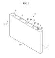
FIG. 1 is a perspective view of a rechargeable battery according to a first embodiment of the present invention. -
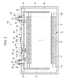
FIG. 2 is a cross-sectional view of the rechargeable battery taken along the line II-II ofFIG. 1 . -
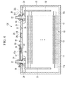
FIG. 3 is a cross-sectional view of a rechargeable battery according to a second embodiment of the present invention. -
FIG. 4 is a cross-sectional view of a rechargeable battery according to a third embodiment of the present invention. - As used herein, in this disclosure, the term 'deformable plate' refers to all kinds of plates to be capable of being modified according to pressure increase, but is not particularly limited.
- The present invention will be described more fully hereinafter with reference to the accompanying drawings, in which exemplary embodiments of the invention are shown. As those skilled in the art would realize, the described embodiments may be modified in various different ways, all without departing from the scope of the present invention. In the specification and drawings, like reference numerals designate like elements.
-
FIG. 1 is a perspective view of a rechargeable battery according to a first embodiment of the present invention, andFIG. 2 is a cross-sectional view of the rechargeable battery taken along the line II-II ofFIG. 1 . - Referring to
FIGS. 1 and2 , therechargeable battery 110 according to the embodiment of the present invention includes anelectrode assembly 10 in which aninsulator separator 13 interposed between afirst electrode 11 and asecond electrode 12 is wound; acase 15 housing theelectrode assembly 10; and acap assembly 20 assembled with a opening of thecase 15. - The
rechargeable battery 110 according to the first embodiment is described with reference to a prismatic lithium ion rechargeable battery as an example. However, the present invention is not limited thereto, but it is applicable to the various types such as a lithium polymer battery, a cylindrical battery and so on. - The
first electrode 11 and thesecond electrode 12 include a coating region where active material is coated on a current collector formed of a thin plate of a metal foil and anuncoated region first electrode 11 is designated to a positive electrode, and thesecond electrode 12 is a negative electrode. However, it is only exemplary, and thefirst electrode 11 may be a negative electrode, and thesecond electrode 12 may be a positive electrode. - The
uncoated region 11 a of first electrode is formed on the one side end of thefirst electrode 11 along with the length direction of thefirst electrode 11; theuncoated region 12a of second electrode is formed on the other side end of thesecond electrode 12 along with the length direction of thesecond electrode 12. Thefirst electrode 11 and thesecond electrode 12 interpose aninsulator separator 13 therebetween and are spirally wound. - However, the
electrode assembly 10 may be provided by alternatively laminating thefirst electrode 11 and thesecond electrode 12 including a plurality of sheets with an interposedseparator 13 therebetween. - A
case 15 is preferably approximately cuboid and has an opening such that one surface of the case is opened. Thecap assembly 20 includes acap plate 28 covering the opening ofcase 15, afirst terminal 21 electrically connected to thefirst electrode 11, asecond terminal 22 electrically connected to thesecond electrode 12, a first tab or first short-circuit tab 42 electrically connected with thefirst terminal 21, a second tab or second short-circuit tab 46 electrically connected with thesecond terminal 22, and adeformable plate 41 fixed on thecap plate 28. - The
cap plate 28 preferably has a thin plate and is assembled to close the opening ofcase 15. A sealingplug 27 is provided in an electrolyte injection opening 29 of thecap plate 28. The cap plate includes avent plate 26 provided in thevent hole 24 and having anotch 26a to be opened under the predetermined pressure. - The
first terminal 21 and thesecond terminal 22 are formed to penetrate through thecap plate 28, and a supported flange is formed under thecap plate 28. The circumference of the protruded upper column ofcap plate 28 is processed to a screw. In addition, nuts 35 supported above are jointed withterminals - An
upper gasket 38 and alower gasket 39 are provided between thecap plate 28 and thefirst terminal 21 and thesecond terminal 22 to seal and insulate betweenterminals cap plate 28. - The
first terminal 21 electrically connects with thefirst electrode 11 by means of thefirst lead tab 31, and thesecond terminal 22 electrically connects with thesecond electrode 12 by means of thesecond lead tab 32. - However, a lower insulating
member 34 is disposed beneath thecap plate 28, and the lower end ofterminals lead tabs member 34. - The
first lead tab 31 electrically connects thefirst terminal 21 to thefirst electrode 11, and thesecond lead tab 32 electrically connects thesecond terminal 22 to thesecond electrode 12 as in the structure. - The first short-
circuit tab 42 preferably has a substantially plate shape and is disposed in this embodiment under thecap plate 28. In the first short-circuit tab 42, one side terminal end is welded and fixed on thefirst lead tap 31, and the other side terminal end continues until the below thedeformable plate 41. - According to the present exemplary embodiment, it exemplifies that the first short-
circuit tab 42 is welded and fixed on thefirst lead tab 31, but it is not limited thereto. The first short-circuit tab 42 may be welded and fixed on thefirst terminal 21, or welded and fixed on both thefirst lead tab 31 and thefirst terminal 21. - The second short-
circuit tab 46 preferably also has a substantial plate shape and is in this embodiment disposed under thecap plate 28. One side terminal end of the second short-circuit tab 46 is welded and fixed on thesecond lead tap 32, and the other side terminal end continues until the below thedeformable plate 41. - The first short-
circuit tab 42 and the second short-circuit tab 46 are disposed with leaving space or spaced-apart, so they are not electrically connected. - A short-
circuit hole 25 is formed in acap plate 28, and thedeformable plate 41 is formed under the short-circuit hole 25. - The
deformable plate 41 is welded and joined to thecap plate 28 and includes aedge part 41 a having a flat ring shape and a transformingpart 41 b that is formed inside theedge part 41 a and protrudes in arch curve toward theelectrode assembly 10. - A
connection member 43 is mounted under thedeformable plate 41, and theconnection member 43 is connected to thedeformable plate 41 through a connectingbar 47. - The
connection member 43 is formed to have a larger thickness than that of thedeformable plate 41 and preferably has an approximate disc shape. - The size of the thickness of the
deformable plate 41 may depend on the thickness of the case. For example, the thickness of thedeformable plate 41 may be in the range of 0.3-0.5mm, while the thickness ofconnection member 43 may be in the range of 1mm to 2mm. In general, also holding for the other embodiments described herein, the thickness of the connection member may be preferably at least twice as large than the thickness of the deformable plate, more preferably at least four times as large, even more preferably at least six times as large in order to maintain a short-circuit state. - The connecting
bar 47 is passed between the short-circuit tabs connection member 43 is fixed on the lower end of the connectingbar 47. Thereby, theconnection member 43 is disposed lower than the short-circuit tabs circuit tab 42 and the terminal end of the second short-circuit tab 46 are disposed between theconnection member 43 and thedeformable plate 41. - When the internal pressure of
rechargeable battery 110 is excessively increased, thetransformation part 41 b protruded toward downside is inverted to upside. Thereby, theconnection member 43 is lifted, so as to electrically connect the first short-circuit tab 42 to the second short-circuit tab 46. - The
deformable plate 41 is designated to inversely transform its shape under the predetermined pressure, such that a limit to an increase of its thickness exists. Accordingly, when thedeformable plate 41 directly contacts the short-circuit tabs deformable plate 41 may be fused due to an excessive current passing as a result of the short circuit. Thereby, problems of an interruption of the short-circuit state may occur. - However, according to the present exemplary embodiment, since the
connection member 43 contacts the short-circuit tabs - In addition, in view of the state of the art, if a member such as a spring and so on is continuously pressed during normal operation time, its elasticity is decreased or it disappears after the pressing force has been applied for long time. In order to ensure safety of the rechargeable battery with respect to its life-cycle, it is very important for the elements of a rechargeable battery not to decrease its elasticity and to operate under the predetermined pressure during the whole life-cycle. However, the elasticity of a member such as a spring and so on decreases during the life-cycle and stops to work under the predetermined pressure, causing a problem of a deterioration of the safety. According to the present exemplary embodiment, due to the use of a
deformable plate 41, no element is pressured during normal operation time. Therefore, the battery may work under the predetermined pressure even after a long time has elapsed. -
FIG. 3 is a cross-sectional view of a rechargeable battery according to a second embodiment of the present invention. - Referring to
FIG. 3 , therechargeable battery 120 according to another embodiment has the same structure as in the rechargeable battery cell according to the above first embodiment, except for the structure of short-circuit taps and connection members, so the same description is not repeated and incorporated herein. - As shown in
FIG. 3 , therechargeable battery cell 120 according to the present exemplary embodiment includes anelectrode assembly 10, acase 15 inserting theelectrode assembly 10, and acap assembly 50 sealing thecase 15. Thecap assembly 50 includes acap plate 28 assembled with the opening of thecase 15, afirst terminal 21 electrically connecting to thefirst electrode 11 and asecond terminal 22 electrically connecting to thesecond electrode 12. - The
cap plate 28 is a thin plate and has a hollow short-circuit hole 25. - A first
terminal tap 52 is formed to be electrically connected to thefirst terminal 21 and disposed above the short-circuit hole 25. A second short-circuit tab 56 is formed to be electrically connected to thesecond terminal 22 and disposed on the short-circuit hole 25. - The first short-
circuit tab 52 and the second short-circuit tab 56 are disposed with leaving space or spaced apart above thecap plate 28, and they do not directly contact thecap plate 28. - An
deformable plate 51 is provided under the short-circuit hole 25, and aconnection member 53 is welded and fixed with thedeformable plate 51. - The
connection member 53 is welded and fixed to thedeformable plate 51 along its lower end circumference and has a larger thickness than thedeformable plate 51. - When the internal pressure of
rechargeable battery 120 is increased, thedeformable plate 51 is converted to curve toward the upper side to lift theconnection member 53 to the upper side. - The lifted
connection member 53 electrically connects the first short-circuit tab 52 to the second short-circuit tab 56 to induce the short-circuit. - Thereby, according to the present exemplary embodiment, by electrically connecting the terminal taps 52 and 56 an explosion of the battery upon an excessive increase of an internal pressure inside the
rechargeable battery 120 may be prevented. It may also be prevented that heat is excessively generated inside therechargeable battery 120 as a result of the short-circuit current, by disposing all the terminal taps 52 and 56 outside thecase 15. An overheat of thecap plate 28 may be prevented since current is not passed through thecap plate 28. - In addition, since the first short-
circuit tab 52 and the second short-circuit tab 56 are all disposed outside, heat may be easily released toward outside through the first short-circuit tab 52 and the second short-circuit tab 56. It may prevent the electrolyte solution from firing since the short-circuit part leaves space from the electrolyte solution. -
FIG. 4 is a cross-sectional view of a rechargeable battery according to a third embodiment of the present invention. - The
rechargeable battery 130 according to the present exemplary embodiment includes anelectrode assembly 10, a case hosing theelectrode assembly 10, and acap assembly 60 sealing thecase 15. Thecap assembly 60 includes acap plate 28 assembled with the opening ofcase 15, afirst terminal 21 electrically connected to thefirst electrode 11, and asecond terminal 22 electrically connected to thesecond electrode 12. - The
cap plate 28 is preferably a thin plate and preferably has a hollow short-circuit hole 25. - A first short-
circuit tab 67 disposed on the short-circuit hole 25 is formed to be electrically connected with thefirst terminal 21. - The first short-
circuit tab 67 has an approximate plate shape and disposed above thecap plate 28. Thefirst terminal 21 is inserted in the hole of firstterminal tap 67 and fixed by anut 35 formed above the first terminal tap and jointed with thefirst terminal 21. Thereby, the first short-circuit tab 67 is electrically connected to thefirst terminal 21 through anut 35. - A connecting
tap 36 is formed between thesecond terminal 22 and thenut 35. The connectingtap 36 plays a role of electrically connecting between thesecond terminal 22 and thecap plate 28. Asecond terminal 22 is inserted in a hole of connectingtap 36. The connectingtap 36 is fastened to thecap plate 28 through anut 35 formed there above. According to the present exemplary embodiment, thecap plate 28 becomes a second short-circuit tab. - An
upper insulation member 68 is formed between the first short-circuit tap 67 and thecap plate 28 for the insulation. A part ofupper insulation member 68 surrounds thefirst terminal 21, and the edge surrounds the side end of the first short-circuit tab 67. The first short-circuit tab 67 is stably supported through theupper insulation member 67, so it may minimize the deformation even when it is pressed by the transformation ofdeformable plate 61. - In addition, a
circular vent 67a is formed in the part corresponding to the upper area ofterminal hole 25 in the first short-circuit tap 67. A hole is formed on the area corresponding to the upper area ofterminal hole 25 in theupper insulation member 68. - A
deformable plate 61 is provided above the short-circuit hole 25. Aconnection member 63 is welded and fixed on thedeformable plate 61. Thereby, thedeformable plate 61 is electrically connected to thesecond electrode 12 by means of thecap plate 28. - The
deformable plate 61 has the same structure as in the first embodiment. Theconnection member 63 includes a material having a higher melting point than that of thedeformable plate 61 and has an approximate disc shape. In addition, theconnection member 63 is welded and fixed to thedeformable plate 61 along the circumference of its lower end thereof. - When the internal pressure of
rechargeable battery 130 is increased, thedeformable plate 61 is transformed into convex toward upper side to lift theconnection member 63 toward the upper side. The lifted intermediatedmember 63 induces the short-circuit by electrically connecting the first short-circuit tab 67 to thecap plate 28, so as to prevent the rechargeable battery from the explosion. - While this invention has been described in connection with what is presently considered to be practical exemplary embodiments, it is to be understood that the invention is not limited to the disclosed embodiments, but, on the contrary, is intended to cover various modifications and equivalent arrangements included within the scope of the appended claims.
Claims (15)
- A rechargeable battery comprising:an electrode assembly (10) having a first electrode (11), a second electrode (12), and a separator (13) interposed between the first and the second electrodes (11, 12);a case (15) for mounting the electrode assembly (10) therein; anda cap assembly (20, 50, 60) comprising:a cap plate (28) for closing an opening of the case (15);a deformable plate (41, 51, 61) attached to the cap plate (28), the deformable plate (41, 51, 61) being in communication with the inside of the battery (110, 120, 130) and adapted to be deformed, anda conductive connection member (43, 53, 63) coupled to the deformable plate (41, 51, 61) and adapted to connect the first electrode (11) with the second electrode (12) upon deformation of the deformable plate (41, 51, 61).
- Rechargeable battery according to claim 1, wherein the deformable plate (41, 51, 61):is adapted to be deformed upon an increase of an internal pressure inside the battery; and/orcomprises a curved or an arc or a convex shaped deformable part, under normal operation conditions curved toward and protruding into the interior of the battery (110, 130, 140); and/orincludes an edge part (41 a) and a deformable part (41 b) formed on the inner side of the edge part (41 a) and protruding in an arch curve toward the interior of the battery.
- Rechargeable battery according to claim 1 or 2, wherein the connection member (43, 53, 63): has a larger thickness than the deformable plate (41, 51, 61); and/or comprises a material having a higher melting point than a material of the deformable plate (41, 51, 61).
- Rechargeable battery according to any of the previous claims, wherein the connection member (43, 53, 63) is directly affixed to the deformable plate (51, 61), and/or is affixed to the deformable plate (41) via a connecting bar (47).
- Rechargeable battery according to any of the previous claims, wherein the connection member (43, 53, 63) comprises at least one of the group consisting of aluminum, copper, and stainless-steel, and the deformable plate (41, 51, 61) comprises at least one of the group consisting of aluminum and stainless-steel.
- Rechargeable battery according to any of the previous claims, wherein the cap assembly (20, 50, 60) further comprises a first tab (42, 52, 67) electrically connected to the first electrode (11).
- Rechargeable battery according to claim 6, wherein the first tab (42, 52, 67):has a planar shape; and/oris disposed below the cap plate (28) and is one side end connected to the first electrode (11) and on the other side end continues until below the deformable plate (41, 51, 61); oris disposed above the cap plate (28) and is one side end connected to the first electrode (11) via a first terminal (21) and on the other side end continues until above the deformable plate (41, 51, 61).
- Rechargeable battery according to at least one of claims 6 or 7, wherein the cap assembly (20, 50) further comprises a second tab (46, 56) electrically connected to the second electrode (12), the first tab (42, 52) and the second tab (46, 56) being disposed spaced apart from each other, wherein the connection member (43, 53) is adapted to electrically connect the first tab (42, 52) with the second tab (46, 56) upon deformation of the deformable plate (41, 51) to short-circuit the first electrode (11) and the second electrode (12).
- Rechargeable battery according to claim 8, wherein the deformable plate (41, 51) is formed below a short-circuit hole (25) provided in the cap plate (28) and/or wherein a short-circuit hole (25) is closed by the deformable plate (41, 51, 61).
- Rechargeable battery according to claim 8 or 9, wherein the first tab (42) and the second tap (46) are disposed below the cap plate (28) and the connection member (43) is disposed below the first and second tab (42, 46) and attached to the deformable plate (41) via a connecting bar (47).
- Rechargeable battery according to at least one of claims 8 to 10, wherein a first lead tab (31) is provided to electrically connect the first tab (42) to the first electrode (11) and a second lead tab (32) is provided to electrically connect the second tab (46) with the second electrode (11).
- Rechargeable battery according to claim 8, wherein the first tab (42) and the second tap (46) are disposed above the cap plate (28) and the connection member (43) is disposed below the first and second tab (42, 46) but above the deformable plate (41, 51).
- Rechargeable battery according to at least one of claims 1 to 3, wherein the connection member (63) and the deformable plate (61) are made out of conductive material, the deformable plate (61) being electrically connected to the second electrode (12) via the cap plate (28), and the cap assembly (60) further comprises a first tab (67) electrically connected to the first electrode (11), wherein the connection member (63) is adapted to electrically contact the first tab (67) upon deformation of the deformable plate (61).
- Rechargeable battery according to claim 13, wherein the cap assembly (60) further comprises an upper insulating member (68) such that the first tab (67) is coupled to the cap plate (28) with the upper insulating member (28) interposed therebetween to electrically isolate the first tab (67) from the cap plate (28).
- Rechargeable battery according to any of the previous claims, wherein a circular vent (67a) is formed in the first tab (67) above and corresponding to the location of a short-circuit hole (25) formed in the cap plate.
Applications Claiming Priority (2)
| Application Number | Priority Date | Filing Date | Title |
|---|---|---|---|
| US23896509P | 2009-09-01 | 2009-09-01 | |
| US12/781,656 US8877361B2 (en) | 2009-09-01 | 2010-05-17 | Rechargeable battery |
Publications (2)
| Publication Number | Publication Date |
|---|---|
| EP2299512A1 true EP2299512A1 (en) | 2011-03-23 |
| EP2299512B1 EP2299512B1 (en) | 2013-04-24 |
Family
ID=42358299
Family Applications (1)
| Application Number | Title | Priority Date | Filing Date |
|---|---|---|---|
| EP10164550.5A Active EP2299512B1 (en) | 2009-09-01 | 2010-06-01 | Cap assembly for a rechargeable battery |
Country Status (5)
| Country | Link |
|---|---|
| US (1) | US8877361B2 (en) |
| EP (1) | EP2299512B1 (en) |
| JP (1) | JP5275298B2 (en) |
| KR (1) | KR101201746B1 (en) |
| CN (1) | CN102005597B (en) |
Cited By (14)
| Publication number | Priority date | Publication date | Assignee | Title |
|---|---|---|---|---|
| EP2432042A1 (en) * | 2010-09-17 | 2012-03-21 | SB LiMotive Co., Ltd. | Rechargeable battery |
| EP2533326A1 (en) * | 2011-06-08 | 2012-12-12 | SB LiMotive Co., Ltd. | Rechargeable battery |
| EP2595214A1 (en) * | 2011-11-17 | 2013-05-22 | Samsung SDI Co., Ltd. | Rechargeable battery |
| WO2013087304A1 (en) * | 2011-12-15 | 2013-06-20 | Robert Bosch Gmbh | Battery cell, battery, motor vehicle |
| EP2733766A1 (en) * | 2012-11-20 | 2014-05-21 | Samsung SDI Co., Ltd. | Rechargeable battery |
| CN103996816A (en) * | 2013-02-14 | 2014-08-20 | 三星Sdi株式会社 | Battery module |
| US8877361B2 (en) | 2009-09-01 | 2014-11-04 | Samsung Sdi Co., Ltd. | Rechargeable battery |
| US9012050B2 (en) | 2011-07-26 | 2015-04-21 | Samsung Sdi Co., Ltd. | Rechargeable battery |
| EP2905828A1 (en) * | 2014-02-05 | 2015-08-12 | Samsung SDI Co., Ltd. | Rechargeable battery |
| US9246140B2 (en) | 2009-07-09 | 2016-01-26 | Samsung Sdi Co., Ltd. | Rechargeable battery with a cap assembly having a first tab located outside of the case |
| US9478774B2 (en) | 2010-12-02 | 2016-10-25 | Samsung Sdi Co., Ltd. | Rechargeable battery |
| US9634299B2 (en) | 2011-09-06 | 2017-04-25 | Samsung Sdi Co., Ltd. | Rechargeable battery |
| EP3376554A1 (en) * | 2017-03-17 | 2018-09-19 | Lithium Energy and Power GmbH & Co. KG | Fast discharge and/or shut down unit, battery cell, cell module or battery, and apparatus |
| WO2019100076A1 (en) * | 2017-11-20 | 2019-05-23 | Johnson Controls Technology Company | Overcharge protection device with uneven terminal pads |
Families Citing this family (63)
| Publication number | Priority date | Publication date | Assignee | Title |
|---|---|---|---|---|
| KR101097220B1 (en) * | 2009-10-30 | 2011-12-21 | 에스비리모티브 주식회사 | Secondary battery |
| KR101117622B1 (en) * | 2010-05-19 | 2012-02-29 | 에스비리모티브 주식회사 | Rechargeable battery |
| KR101136219B1 (en) * | 2010-06-09 | 2012-04-17 | 에스비리모티브 주식회사 | Secondary battery and method for fabricating the same |
| US9099732B2 (en) * | 2010-06-11 | 2015-08-04 | Samsung Sdi Co., Ltd. | Rechargeable battery having a fuse with an insulating blocking member |
| US10115958B2 (en) * | 2010-08-17 | 2018-10-30 | Gs Yuasa International Ltd. | Manufacturing method of electric storage device and electric storage device |
| KR101222306B1 (en) * | 2011-01-31 | 2013-01-16 | 로베르트 보쉬 게엠베하 | Rechargeable battery |
| US8753765B2 (en) | 2011-03-14 | 2014-06-17 | Samsung Sdi Co., Ltd. | Secondary battery |
| KR101243475B1 (en) * | 2011-03-30 | 2013-03-13 | 로베르트 보쉬 게엠베하 | Secondary battery including short-member |
| JP5382205B2 (en) | 2011-04-01 | 2014-01-08 | トヨタ自動車株式会社 | Power storage device |
| KR101254886B1 (en) | 2011-04-04 | 2013-04-15 | 로베르트 보쉬 게엠베하 | Secondary battery |
| KR101254871B1 (en) | 2011-04-18 | 2013-04-15 | 로베르트 보쉬 게엠베하 | Secondary battery |
| KR101265202B1 (en) * | 2011-06-08 | 2013-05-27 | 로베르트 보쉬 게엠베하 | Rechargeable battery |
| KR101275791B1 (en) | 2011-09-09 | 2013-06-18 | 로베르트 보쉬 게엠베하 | Rechargeable battery and module thereof |
| KR101683203B1 (en) * | 2011-09-19 | 2016-12-21 | 삼성에스디아이 주식회사 | Rechargeable battery |
| KR101711977B1 (en) * | 2011-10-25 | 2017-03-06 | 삼성에스디아이 주식회사 | Rechargeable battery |
| CN103107295A (en) * | 2011-11-14 | 2013-05-15 | 丁振荣 | Sealing ring, nut cap, cell, lithium battery and nut cap assembly method |
| KR101696001B1 (en) * | 2012-03-23 | 2017-01-12 | 삼성에스디아이 주식회사 | Secondary bttery module |
| CN106058139B (en) * | 2012-04-12 | 2018-12-21 | 株式会社丰田自动织机 | Failure of current device and the electrical storage device for using failure of current device |
| JP5945989B2 (en) * | 2012-07-19 | 2016-07-05 | 株式会社豊田自動織機 | Power storage device with current interrupt device |
| US9806317B2 (en) | 2012-08-03 | 2017-10-31 | Kabushiki Kaisha Toyota Jidoshokki | Electric storage device |
| JP5911772B2 (en) * | 2012-08-09 | 2016-04-27 | 三洋電機株式会社 | Non-aqueous electrolyte secondary battery and manufacturing method thereof |
| CN104781946B (en) * | 2012-11-26 | 2017-12-12 | 日立汽车系统株式会社 | Square secondary cell |
| CN203038987U (en) * | 2012-12-03 | 2013-07-03 | 宁德新能源科技有限公司 | Power battery top cover with current interruption device |
| KR102035577B1 (en) * | 2012-12-11 | 2019-10-23 | 대우조선해양 주식회사 | Purge system for water ballast tank |
| CN103050646B (en) * | 2012-12-19 | 2016-04-13 | 宁德新能源科技有限公司 | A kind of top cover structure of power battery |
| KR101666258B1 (en) * | 2013-01-23 | 2016-10-13 | 삼성에스디아이 주식회사 | Rechargeable battery |
| KR101675618B1 (en) | 2013-02-20 | 2016-11-11 | 삼성에스디아이 주식회사 | Secondary battery |
| CN203165987U (en) * | 2013-04-09 | 2013-08-28 | 宁德时代新能源科技有限公司 | Lithium-ion battery and safety overturning valve for over-charging safety protection device of lithium-ion battery |
| KR101690295B1 (en) * | 2013-05-15 | 2017-01-09 | 주식회사 엘지화학 | Overcurrent shut-off device and Secondary battery comprising the same |
| WO2015001716A1 (en) * | 2013-07-01 | 2015-01-08 | 三洋電機株式会社 | Nonaqueous electrolyte secondary battery |
| KR102043458B1 (en) * | 2013-07-29 | 2019-11-11 | 삼성에스디아이 주식회사 | Secondary Battery |
| KR101711992B1 (en) * | 2013-08-05 | 2017-03-03 | 삼성에스디아이 주식회사 | Rechargeable battery having upper insulator member |
| KR101733741B1 (en) * | 2013-10-08 | 2017-05-08 | 삼성에스디아이 주식회사 | Rechargeable battery having connecting member |
| KR102234381B1 (en) * | 2014-01-07 | 2021-03-31 | 삼성에스디아이 주식회사 | Rechargeable battery having heat-resisting member |
| KR102210217B1 (en) | 2014-03-10 | 2021-01-29 | 삼성에스디아이 주식회사 | Rechargeable battery |
| KR102177504B1 (en) * | 2014-04-11 | 2020-11-11 | 삼성에스디아이 주식회사 | Rechargeable battery |
| US9985271B2 (en) * | 2014-07-31 | 2018-05-29 | Johnson Controls Technology Company | Overcharge protection device for a battery module |
| US10008710B2 (en) | 2014-08-04 | 2018-06-26 | Johnson Controls Technology Company | Overcharge protection assembly for a battery module |
| KR102323949B1 (en) * | 2015-03-03 | 2021-11-08 | 삼성에스디아이 주식회사 | Rechargeable battery having upper cover |
| CN204668368U (en) * | 2015-06-11 | 2015-09-23 | 宁德时代新能源科技有限公司 | Top cover structure of power battery and electrokinetic cell |
| CN107078250B (en) * | 2015-08-25 | 2022-02-22 | Cps科技控股有限公司 | Overcharge protection assembly for battery module |
| WO2017106349A1 (en) | 2015-12-14 | 2017-06-22 | Cadenza Innovation, Inc. | Low profile pressure disconnect device for lithium ion batteries |
| JP6380420B2 (en) * | 2016-02-04 | 2018-08-29 | トヨタ自動車株式会社 | Secondary battery and battery pack |
| JP6821309B2 (en) | 2016-03-07 | 2021-01-27 | 三洋電機株式会社 | Rechargeable battery and rechargeable battery assembly |
| CN116845475A (en) | 2016-08-01 | 2023-10-03 | Cps 科技控股有限公司 | Overcharge protection assembly for battery cell |
| US11233289B2 (en) | 2016-08-01 | 2022-01-25 | Cps Technology Holdings Llc | Weldable aluminum terminal pads of an electrochemical cell |
| WO2018026850A1 (en) * | 2016-08-01 | 2018-02-08 | Johnson Controls Technology Company | Overcharge protection systems having dual spiral disk features for prismatic lithium ion battery cells |
| JP6493352B2 (en) | 2016-10-13 | 2019-04-03 | トヨタ自動車株式会社 | Secondary battery |
| CN106450475B (en) * | 2016-11-15 | 2019-08-02 | 宁德时代新能源科技股份有限公司 | Secondary battery and battery module |
| CN106450136B (en) * | 2016-11-15 | 2020-02-14 | 宁德时代新能源科技股份有限公司 | Secondary battery and battery module |
| KR102201342B1 (en) * | 2017-07-06 | 2021-01-08 | 주식회사 엘지화학 | Battery module, battery pack including the same, and vehicle including the same |
| CN107579175A (en) * | 2017-07-28 | 2018-01-12 | 深圳市欣迪盟新能源科技股份有限公司 | Battery |
| US10622636B2 (en) * | 2017-09-29 | 2020-04-14 | International Business Machines Corporation | High-capacity rechargeable battery stacks containing a spalled cathode material |
| US10601033B2 (en) | 2017-09-29 | 2020-03-24 | International Business Machines Corporation | High-performance rechargeable batteries having a spalled and textured cathode layer |
| CN109671878B (en) * | 2017-10-17 | 2021-09-21 | 宁德时代新能源科技股份有限公司 | Battery top cap subassembly and secondary cell |
| US20190123336A1 (en) * | 2017-10-23 | 2019-04-25 | International Business Machines Corporation | Solid-state rechargeable battery having fast charge speed |
| US10644282B2 (en) | 2018-01-23 | 2020-05-05 | Nio Usa, Inc. | Staggered battery cell array with two-dimensional inline terminal edges |
| KR20200106965A (en) * | 2018-01-31 | 2020-09-15 | 히타치가세이가부시끼가이샤 | Short circuit protection member, storage battery, power storage device and power storage system |
| US10892465B2 (en) * | 2018-03-22 | 2021-01-12 | Nio Usa, Inc. | Battery cell cover including terminal short isolation feature |
| US10741889B2 (en) | 2018-03-22 | 2020-08-11 | Nio Usa, Inc. | Multiple-zone thermocouple battery module temperature monitoring system |
| US10784486B2 (en) | 2018-02-20 | 2020-09-22 | Nio Usa, Inc. | Uniform current density tapered busbar |
| US10741808B2 (en) | 2018-03-15 | 2020-08-11 | Nio Usa, Inc. | Unified battery module with integrated battery cell structural support |
| US10707471B2 (en) | 2018-03-22 | 2020-07-07 | Nio Usa, Inc. | Single side cell-to-cell battery module interconnection |
Citations (3)
| Publication number | Priority date | Publication date | Assignee | Title |
|---|---|---|---|---|
| JPH10326610A (en) * | 1997-05-27 | 1998-12-08 | Hitachi Ltd | Non-aqueous electrolyte secondary battery |
| JPH117931A (en) * | 1997-06-18 | 1999-01-12 | Hitachi Ltd | Secondary battery |
| JP2004319463A (en) * | 2003-03-28 | 2004-11-11 | Matsushita Electric Ind Co Ltd | Secondary battery |
Family Cites Families (116)
| Publication number | Priority date | Publication date | Assignee | Title |
|---|---|---|---|---|
| US4209571A (en) * | 1975-08-28 | 1980-06-24 | Gte Laboratories Incorporated | Primary electrochemical cell |
| US4879187A (en) | 1987-10-22 | 1989-11-07 | Eveready Battery Company | Battery terminal fuse |
| US5143860A (en) * | 1987-12-23 | 1992-09-01 | Texas Instruments Incorporated | High density EPROM fabricaiton method having sidewall floating gates |
| US4945014A (en) * | 1988-02-10 | 1990-07-31 | Mitsubishi Petrochemical Co., Ltd. | Secondary battery |
| JPH0562664A (en) | 1991-09-02 | 1993-03-12 | Matsushita Electric Ind Co Ltd | Explosion proof type nonaqueous secondary battery |
| JPH05251290A (en) | 1992-03-07 | 1993-09-28 | Hitachi Aic Inc | Cased capacitor |
| JPH05275088A (en) | 1992-03-27 | 1993-10-22 | Yuasa Corp | Laminated thin type battery |
| US5523178A (en) * | 1992-12-14 | 1996-06-04 | Nippondenso Co., Ltd. | Chemical cell |
| JP3232767B2 (en) | 1993-03-31 | 2001-11-26 | 株式会社デンソー | Chemical battery with safety mechanism |
| JPH0737572A (en) | 1993-07-22 | 1995-02-07 | Japan Storage Battery Co Ltd | Lithium battery |
| JP3573293B2 (en) | 1993-11-24 | 2004-10-06 | 日本電池株式会社 | battery |
| JPH0850920A (en) | 1994-08-08 | 1996-02-20 | Toyo Takasago Kandenchi Kk | Square type lithium secondary cell |
| US5707756A (en) * | 1994-11-29 | 1998-01-13 | Fuji Photo Film Co., Ltd. | Non-aqueous secondary battery |
| JPH08185850A (en) | 1994-12-27 | 1996-07-16 | Sony Corp | Lithium ion secondary battery |
| JPH09106804A (en) * | 1995-10-09 | 1997-04-22 | Wako Denshi Kk | Safety apparatus for battery |
| JPH1074500A (en) | 1996-08-30 | 1998-03-17 | Sanyo Electric Co Ltd | Sealed battery and its manufacture |
| TW332342B (en) * | 1996-11-11 | 1998-05-21 | Mos Electronics Taiwan Inc | Structure and fabrication method of split-gate flash memory |
| JPH10188946A (en) | 1996-12-20 | 1998-07-21 | Toyo Takasago Kandenchi Kk | Rectangular battery with inner short circuit protecting device |
| JP3464750B2 (en) | 1997-01-21 | 2003-11-10 | 東芝電池株式会社 | Lithium secondary battery |
| US5800937A (en) * | 1997-05-02 | 1998-09-01 | Motorola, Inc. | Current interrupt device for secondary batteries |
| US6069551A (en) * | 1997-05-02 | 2000-05-30 | Therm-O-Disc, Incorporated | Thermal switch assembly |
| JPH1140203A (en) | 1997-07-14 | 1999-02-12 | Hitachi Ltd | Secondary battery |
| JPH11191436A (en) * | 1997-12-26 | 1999-07-13 | Hitachi Ltd | Capacitor protector |
| KR200283452Y1 (en) | 1997-12-30 | 2002-09-19 | 삼성에스디아이 주식회사 | Non-Aqueous Solution Secondary Battery |
| TW502467B (en) * | 1998-03-18 | 2002-09-11 | Toshiba Battery | Battery, lead member for battery connection, and battery pack using the same |
| JP4303801B2 (en) | 1998-03-25 | 2009-07-29 | ワコー電子株式会社 | Secondary battery safety device |
| JPH11307076A (en) | 1998-04-24 | 1999-11-05 | Sony Corp | Secondary battery |
| JP3497380B2 (en) * | 1998-06-02 | 2004-02-16 | 日本碍子株式会社 | Lithium secondary battery |
| KR100270958B1 (en) * | 1998-07-10 | 2000-11-01 | 윤종용 | Non-volatile semiconductor device and method for fabricating the same |
| DE19837909C2 (en) * | 1998-08-20 | 2001-05-17 | Implex Hear Tech Ag | Protection device for a multi-rechargeable electrochemical battery |
| US6524739B1 (en) * | 1998-08-25 | 2003-02-25 | Matsushita Electric Industrial Co., Ltd. | Secondary battery |
| JP2000082457A (en) | 1998-09-04 | 2000-03-21 | Toyo Kohan Co Ltd | Electric/electronic equipment and part safeguard, sealed battery safeguard using it and sealed battery using it |
| JP2000182598A (en) | 1998-12-16 | 2000-06-30 | Hitachi Ltd | Nonaqueous electrolyte secondary battery and electrothermal relay for battery |
| KR100358062B1 (en) * | 1998-12-30 | 2003-01-24 | 주식회사 하이닉스반도체 | Flash memory cell and method for manufacturing the same |
| JP3693844B2 (en) | 1999-03-01 | 2005-09-14 | アルプス電気株式会社 | Battery-sensitive piezoelectric path blocking mechanism |
| FR2796205B1 (en) * | 1999-07-08 | 2001-10-05 | Cit Alcatel | WATERPROOF ELECTROCHEMICAL ACCUMULATOR COMPRISING AN ALUMINUM RECOVERY DEVICE |
| KR100358224B1 (en) | 1999-07-31 | 2002-10-25 | 주식회사 엘지화학 | Lithium secondary battery |
| US6342826B1 (en) | 1999-08-11 | 2002-01-29 | Therm-O-Disc, Incorporated | Pressure and temperature responsive switch assembly |
| US6525371B2 (en) * | 1999-09-22 | 2003-02-25 | International Business Machines Corporation | Self-aligned non-volatile random access memory cell and process to make the same |
| KR100349908B1 (en) * | 1999-12-15 | 2002-08-22 | 삼성에스디아이 주식회사 | Prismatic type sealed battery |
| JP2001202946A (en) | 2000-01-18 | 2001-07-27 | Nec Corp | Secondary battery with nonaqueous electrolytic solution |
| US6403251B1 (en) * | 2000-01-31 | 2002-06-11 | Moltech Power Systems, Inc | Battery pack with multiple secure modules |
| JP2001357834A (en) | 2000-06-16 | 2001-12-26 | Japan Storage Battery Co Ltd | Battery |
| JP3653468B2 (en) * | 2000-12-28 | 2005-05-25 | 三洋電機株式会社 | Battery pack with built-in breaker |
| JP2002216743A (en) | 2001-01-19 | 2002-08-02 | Alps Electric Co Ltd | Pressure cutoff sensor for battery |
| FR2821983B1 (en) | 2001-03-07 | 2003-08-15 | Schneider Electric Ind Sa | CONNECTION DEVICE FOR ELECTRIC BATTERY |
| TW480680B (en) * | 2001-04-03 | 2002-03-21 | Nanya Technology Corp | Method for producing self-aligned separated gate-type flash memory cell |
| US6730430B2 (en) | 2001-07-09 | 2004-05-04 | Nan Ya Plastics Corporation | Explosion-proof safety structure for column shape lithium battery |
| JP4645001B2 (en) | 2001-07-11 | 2011-03-09 | 株式会社Gsユアサ | battery |
| CN1252843C (en) | 2001-07-11 | 2006-04-19 | 能元科技股份有限公司 | Safety protection structure of square cell |
| JP4154136B2 (en) | 2001-08-06 | 2008-09-24 | 松下電器産業株式会社 | Square sealed battery |
| WO2003015195A1 (en) * | 2001-08-07 | 2003-02-20 | Matsushita Electric Industrial Co., Ltd. | Non-aqueous electrolytic secondary battery |
| JP2003051304A (en) | 2001-08-07 | 2003-02-21 | Matsushita Electric Ind Co Ltd | Nonaqueous electrolyte secondary battery |
| KR100420146B1 (en) | 2001-10-18 | 2004-03-02 | 삼성에스디아이 주식회사 | Secondary battery mounting thermal protector |
| JP2003197178A (en) | 2001-12-25 | 2003-07-11 | Mitsubishi Heavy Ind Ltd | Secondary battery |
| JP2003223886A (en) | 2002-01-30 | 2003-08-08 | Sanyo Gs Soft Energy Co Ltd | Battery |
| JP2003234055A (en) * | 2002-02-12 | 2003-08-22 | Texas Instr Japan Ltd | Overvoltage protector and battery protective system using the same |
| JP4629952B2 (en) * | 2002-02-13 | 2011-02-09 | パナソニック株式会社 | Manufacturing method of secondary battery |
| JP4967216B2 (en) | 2003-12-05 | 2012-07-04 | 株式会社Gsユアサ | Non-aqueous electrolyte battery |
| JP2004022477A (en) | 2002-06-20 | 2004-01-22 | Matsushita Electric Ind Co Ltd | Battery |
| JP2004071265A (en) * | 2002-08-05 | 2004-03-04 | Sanyo Electric Co Ltd | Battery |
| JP2004087194A (en) | 2002-08-23 | 2004-03-18 | Nok Corp | Sealing plate |
| KR100477750B1 (en) * | 2002-09-23 | 2005-03-18 | 삼성에스디아이 주식회사 | Electorde assembly for lithium ion cell and lithium ion cell using the same |
| JP2004273139A (en) | 2003-03-05 | 2004-09-30 | Canon Inc | Lithium secondary battery |
| JP4259890B2 (en) * | 2003-03-07 | 2009-04-30 | 三洋電機株式会社 | Sealed storage battery |
| JP2005032477A (en) | 2003-07-08 | 2005-02-03 | Toyota Motor Corp | Battery and automobile mounting it |
| JP2005044626A (en) | 2003-07-22 | 2005-02-17 | Sanyo Gs Soft Energy Co Ltd | Battery |
| KR100516772B1 (en) * | 2003-08-22 | 2005-09-22 | 삼성에스디아이 주식회사 | Secondary Battery having a Tap in Short Part of Can |
| JP4953551B2 (en) * | 2003-10-31 | 2012-06-13 | 三洋電機株式会社 | Sealed battery |
| US7029968B2 (en) * | 2003-12-05 | 2006-04-18 | Taiwan Semiconductor Manufacturing Company, Ltd. | Method of forming a PIP capacitor |
| US7315056B2 (en) * | 2004-06-07 | 2008-01-01 | Silicon Storage Technology, Inc. | Semiconductor memory array of floating gate memory cells with program/erase and select gates |
| JP2006012602A (en) | 2004-06-25 | 2006-01-12 | Japan Storage Battery Co Ltd | Storage battery |
| KR100619631B1 (en) | 2004-08-31 | 2006-09-12 | 주식회사 엘지화학 | Improved Lithium Secondary Battery |
| KR100624919B1 (en) * | 2004-09-22 | 2006-09-15 | 삼성에스디아이 주식회사 | Secondary Battery |
| KR20060039955A (en) | 2004-11-02 | 2006-05-10 | 유니썸테크놀로지 주식회사 | Safety apparatus for battery |
| WO2006049167A1 (en) * | 2004-11-08 | 2006-05-11 | Sony Corporation | Battery and center pin |
| KR100614377B1 (en) * | 2004-11-15 | 2006-08-21 | 삼성에스디아이 주식회사 | Secondary Battery |
| JP2006147180A (en) | 2004-11-16 | 2006-06-08 | Toshiba Corp | Non-aqueous electrolyte secondary battery |
| CN1655389A (en) * | 2005-03-04 | 2005-08-17 | 北京中信国安盟固利新材料技术研究院有限公司 | High capacity lithium ion secondary battery with metal case |
| KR100614376B1 (en) | 2005-04-25 | 2006-08-22 | 삼성에스디아이 주식회사 | Can type lithium secondary battery |
| US7969015B2 (en) * | 2005-06-14 | 2011-06-28 | Cufer Asset Ltd. L.L.C. | Inverse chip connector |
| US7364970B2 (en) * | 2005-09-30 | 2008-04-29 | Freescale Semiconductor, Inc. | Method of making a multi-bit non-volatile memory (NVM) cell and structure |
| KR100693115B1 (en) | 2005-11-08 | 2007-03-12 | 주식회사 비츠로셀 | Cathode lead having function as a fuse |
| KR100878702B1 (en) * | 2005-11-30 | 2009-01-14 | 주식회사 엘지화학 | Safety Device for Secondary Battery and Battery Pack Employed with the Same |
| JP4848860B2 (en) * | 2006-01-13 | 2011-12-28 | ソニー株式会社 | battery |
| KR100878701B1 (en) * | 2006-03-13 | 2009-01-14 | 주식회사 엘지화학 | High Rate Charging and Discharging Cylindrical Secondary Battery |
| KR100906253B1 (en) | 2006-05-01 | 2009-07-07 | 주식회사 엘지화학 | Secondary Battery Having Electrode With Self Cutting Part To Be Destructed On Application Of Over-Current |
| JP2008027668A (en) | 2006-07-19 | 2008-02-07 | Sony Corp | Battery |
| KR20080025437A (en) | 2006-09-18 | 2008-03-21 | 주식회사 엘지화학 | Secondary battery capable of adjusting position of electrode terminal and having improved safety |
| KR100880321B1 (en) * | 2006-12-14 | 2009-01-28 | 삼성에스디아이 주식회사 | Secondary battery |
| JP4609432B2 (en) | 2007-01-19 | 2011-01-12 | 住友電気工業株式会社 | Lead terminal for power storage device with fuse and non-aqueous electrolyte power storage device |
| JP5271498B2 (en) | 2007-01-26 | 2013-08-21 | 三菱重工業株式会社 | Lithium secondary battery and battery pack |
| JP2008218132A (en) | 2007-03-02 | 2008-09-18 | Matsushita Electric Ind Co Ltd | Sealed battery |
| KR100870349B1 (en) | 2007-03-16 | 2008-11-25 | 삼성에스디아이 주식회사 | Terminal of ProtectCircuit Module and Secondary Battery of using the same |
| KR100922352B1 (en) * | 2007-10-02 | 2009-10-21 | 삼성에스디아이 주식회사 | Rechargeable battery |
| JP5314350B2 (en) | 2008-07-25 | 2013-10-16 | 三菱重工業株式会社 | Battery pack container and battery pack |
| JP2010033949A (en) * | 2008-07-30 | 2010-02-12 | Panasonic Corp | Battery |
| JP5288973B2 (en) * | 2008-09-29 | 2013-09-11 | 三洋電機株式会社 | Rectangular secondary battery and battery module |
| JP5418809B2 (en) | 2008-10-16 | 2014-02-19 | 株式会社Gsユアサ | Battery and manufacturing method thereof |
| KR20100052885A (en) | 2008-11-11 | 2010-05-20 | 주식회사 하이닉스반도체 | Semiconductor memory device |
| US8486546B2 (en) | 2008-12-01 | 2013-07-16 | Samsung Sdi Co., Ltd. | Cap assembly and secondary battery using the same with notched vent member |
| KR101023104B1 (en) | 2008-12-26 | 2011-03-24 | 에스비리모티브 주식회사 | Rechargeable battery |
| KR101085894B1 (en) | 2009-01-29 | 2011-11-23 | 서울대학교산학협력단 | Reduction method for align stiction |
| JP2009105075A (en) | 2009-02-16 | 2009-05-14 | Gs Yuasa Corporation:Kk | Battery |
| KR101041153B1 (en) | 2009-03-04 | 2011-06-13 | 에스비리모티브 주식회사 | Rechargeable battery and module thereof |
| US8323813B2 (en) | 2009-05-14 | 2012-12-04 | Sb Limotive Co., Ltd. | Rechargeable battery including an extensible member |
| US9246140B2 (en) * | 2009-07-09 | 2016-01-26 | Samsung Sdi Co., Ltd. | Rechargeable battery with a cap assembly having a first tab located outside of the case |
| US8236439B2 (en) | 2009-08-14 | 2012-08-07 | Sb Limotive Co., Ltd. | Rechargeable battery |
| US8268478B2 (en) | 2009-08-17 | 2012-09-18 | Sb Limotive Co., Ltd. | Rechargeable battery having anti-vibration member |
| US8877361B2 (en) | 2009-09-01 | 2014-11-04 | Samsung Sdi Co., Ltd. | Rechargeable battery |
| KR101390527B1 (en) | 2009-09-17 | 2014-04-30 | 주식회사 엘지화학 | Ptc-hybrid safety vent, and secondary battery comprising the same |
| KR101222311B1 (en) * | 2010-06-14 | 2013-01-15 | 로베르트 보쉬 게엠베하 | Rechargeable battery |
| US8440336B2 (en) | 2009-12-08 | 2013-05-14 | Samsung Sdi Co., Ltd. | Rechargeable battery with short circuit member |
| US8632911B2 (en) | 2010-01-15 | 2014-01-21 | Samsung Sdi Co., Ltd. | Rechargeable battery |
| KR101042808B1 (en) | 2010-01-26 | 2011-06-20 | 에스비리모티브 주식회사 | Rechargeable battery |
| KR101130294B1 (en) | 2010-03-30 | 2012-08-23 | 에스비리모티브 주식회사 | Rechargeable Battery |
-
2010
- 2010-05-17 US US12/781,656 patent/US8877361B2/en active Active
- 2010-06-01 EP EP10164550.5A patent/EP2299512B1/en active Active
- 2010-06-01 KR KR1020100052011A patent/KR101201746B1/en active IP Right Grant
- 2010-07-02 CN CN201010220632.0A patent/CN102005597B/en active Active
- 2010-07-29 JP JP2010170281A patent/JP5275298B2/en active Active
Patent Citations (3)
| Publication number | Priority date | Publication date | Assignee | Title |
|---|---|---|---|---|
| JPH10326610A (en) * | 1997-05-27 | 1998-12-08 | Hitachi Ltd | Non-aqueous electrolyte secondary battery |
| JPH117931A (en) * | 1997-06-18 | 1999-01-12 | Hitachi Ltd | Secondary battery |
| JP2004319463A (en) * | 2003-03-28 | 2004-11-11 | Matsushita Electric Ind Co Ltd | Secondary battery |
Cited By (23)
| Publication number | Priority date | Publication date | Assignee | Title |
|---|---|---|---|---|
| US9246140B2 (en) | 2009-07-09 | 2016-01-26 | Samsung Sdi Co., Ltd. | Rechargeable battery with a cap assembly having a first tab located outside of the case |
| US8877361B2 (en) | 2009-09-01 | 2014-11-04 | Samsung Sdi Co., Ltd. | Rechargeable battery |
| EP2432042A1 (en) * | 2010-09-17 | 2012-03-21 | SB LiMotive Co., Ltd. | Rechargeable battery |
| US9293756B2 (en) | 2010-09-17 | 2016-03-22 | Samsung Sdi Co., Ltd. | Rechargeable battery |
| US9478774B2 (en) | 2010-12-02 | 2016-10-25 | Samsung Sdi Co., Ltd. | Rechargeable battery |
| EP2533326A1 (en) * | 2011-06-08 | 2012-12-12 | SB LiMotive Co., Ltd. | Rechargeable battery |
| US8642196B2 (en) | 2011-06-08 | 2014-02-04 | Samsung Sdi Co., Ltd. | Rechargeable battery |
| US9012050B2 (en) | 2011-07-26 | 2015-04-21 | Samsung Sdi Co., Ltd. | Rechargeable battery |
| US9634299B2 (en) | 2011-09-06 | 2017-04-25 | Samsung Sdi Co., Ltd. | Rechargeable battery |
| EP2595214A1 (en) * | 2011-11-17 | 2013-05-22 | Samsung SDI Co., Ltd. | Rechargeable battery |
| US9054371B2 (en) | 2011-11-17 | 2015-06-09 | Samsung Sdi Co., Ltd. | Rechargeable battery |
| WO2013087304A1 (en) * | 2011-12-15 | 2013-06-20 | Robert Bosch Gmbh | Battery cell, battery, motor vehicle |
| US10601020B2 (en) | 2011-12-15 | 2020-03-24 | Robert Bosch Gmbh | Battery cell, battery, motor vehicle |
| EP2733766A1 (en) * | 2012-11-20 | 2014-05-21 | Samsung SDI Co., Ltd. | Rechargeable battery |
| US9196892B2 (en) | 2012-11-20 | 2015-11-24 | Samsung Sdi Co., Ltd. | Rechargeable battery |
| CN103996816A (en) * | 2013-02-14 | 2014-08-20 | 三星Sdi株式会社 | Battery module |
| KR20150092682A (en) * | 2014-02-05 | 2015-08-13 | 삼성에스디아이 주식회사 | Rechargeable battery |
| EP2905828A1 (en) * | 2014-02-05 | 2015-08-12 | Samsung SDI Co., Ltd. | Rechargeable battery |
| US11088428B2 (en) | 2014-02-05 | 2021-08-10 | Samsung Sdi Co., Ltd. | Rechargeable battery |
| EP3376554A1 (en) * | 2017-03-17 | 2018-09-19 | Lithium Energy and Power GmbH & Co. KG | Fast discharge and/or shut down unit, battery cell, cell module or battery, and apparatus |
| WO2018166706A1 (en) * | 2017-03-17 | 2018-09-20 | Lithium Energy and Power GmbH & Co. KG | Fast discharge and/or shut down unit, battery cell, cell module or battery, and apparatus |
| WO2019100076A1 (en) * | 2017-11-20 | 2019-05-23 | Johnson Controls Technology Company | Overcharge protection device with uneven terminal pads |
| US11539103B2 (en) | 2017-11-20 | 2022-12-27 | Cps Technology Holdings Llc | Overcharge protection device with uneven terminal pads |
Also Published As
| Publication number | Publication date |
|---|---|
| CN102005597B (en) | 2014-01-15 |
| KR20110025056A (en) | 2011-03-09 |
| JP2011054561A (en) | 2011-03-17 |
| EP2299512B1 (en) | 2013-04-24 |
| JP5275298B2 (en) | 2013-08-28 |
| US20110052949A1 (en) | 2011-03-03 |
| US8877361B2 (en) | 2014-11-04 |
| CN102005597A (en) | 2011-04-06 |
| KR101201746B1 (en) | 2012-11-15 |
Similar Documents
| Publication | Publication Date | Title |
|---|---|---|
| EP2299512B1 (en) | Cap assembly for a rechargeable battery | |
| EP2333871B1 (en) | Rechargeable battery | |
| EP2273587B1 (en) | Rechargeable battery | |
| US8236439B2 (en) | Rechargeable battery | |
| EP2357685B1 (en) | Rechargeable battery | |
| EP2215673B1 (en) | Secondary battery pack of compact structure | |
| US8097358B2 (en) | Cylindrical secondary battery | |
| US9203060B2 (en) | Secondary battery | |
| EP2595214B1 (en) | Rechargeable battery | |
| JP5297441B2 (en) | Secondary battery | |
| EP2793295A2 (en) | Rechargeable battery | |
| US20100159289A1 (en) | Secondary battery | |
| US10096815B2 (en) | Electric power storage device | |
| CN109075304B (en) | Rechargeable battery with diaphragm | |
| US9608257B2 (en) | Rechargeable battery having upper cover | |
| EP2330660B1 (en) | Rechargeable battery | |
| KR20090055791A (en) | Secondary battery pack of compact structure | |
| US8790816B2 (en) | Rechargeable battery |
Legal Events
| Date | Code | Title | Description |
|---|---|---|---|
| PUAI | Public reference made under article 153(3) epc to a published international application that has entered the european phase |
Free format text: ORIGINAL CODE: 0009012 |
|
| 17P | Request for examination filed |
Effective date: 20100601 |
|
| AK | Designated contracting states |
Kind code of ref document: A1 Designated state(s): AL AT BE BG CH CY CZ DE DK EE ES FI FR GB GR HR HU IE IS IT LI LT LU LV MC MK MT NL NO PL PT RO SE SI SK SM TR |
|
| AX | Request for extension of the european patent |
Extension state: BA ME RS |
|
| 17Q | First examination report despatched |
Effective date: 20110307 |
|
| GRAP | Despatch of communication of intention to grant a patent |
Free format text: ORIGINAL CODE: EPIDOSNIGR1 |
|
| RAP1 | Party data changed (applicant data changed or rights of an application transferred) |
Owner name: ROBERT BOSCH GMBH Owner name: SAMSUNG SDI CO., LTD. |
|
| GRAS | Grant fee paid |
Free format text: ORIGINAL CODE: EPIDOSNIGR3 |
|
| GRAA | (expected) grant |
Free format text: ORIGINAL CODE: 0009210 |
|
| AK | Designated contracting states |
Kind code of ref document: B1 Designated state(s): AL AT BE BG CH CY CZ DE DK EE ES FI FR GB GR HR HU IE IS IT LI LT LU LV MC MK MT NL NO PL PT RO SE SI SK SM TR |
|
| REG | Reference to a national code |
Ref country code: GB Ref legal event code: FG4D |
|
| REG | Reference to a national code |
Ref country code: CH Ref legal event code: EP |
|
| REG | Reference to a national code |
Ref country code: AT Ref legal event code: REF Ref document number: 609088 Country of ref document: AT Kind code of ref document: T Effective date: 20130515 |
|
| REG | Reference to a national code |
Ref country code: IE Ref legal event code: FG4D |
|
| REG | Reference to a national code |
Ref country code: DE Ref legal event code: R096 Ref document number: 602010006498 Country of ref document: DE Effective date: 20130620 |
|
| REG | Reference to a national code |
Ref country code: AT Ref legal event code: MK05 Ref document number: 609088 Country of ref document: AT Kind code of ref document: T Effective date: 20130424 |
|
| REG | Reference to a national code |
Ref country code: LT Ref legal event code: MG4D |
|
| REG | Reference to a national code |
Ref country code: NL Ref legal event code: VDEP Effective date: 20130424 |
|
| PG25 | Lapsed in a contracting state [announced via postgrant information from national office to epo] |
Ref country code: SI Free format text: LAPSE BECAUSE OF FAILURE TO SUBMIT A TRANSLATION OF THE DESCRIPTION OR TO PAY THE FEE WITHIN THE PRESCRIBED TIME-LIMIT Effective date: 20130424 Ref country code: LT Free format text: LAPSE BECAUSE OF FAILURE TO SUBMIT A TRANSLATION OF THE DESCRIPTION OR TO PAY THE FEE WITHIN THE PRESCRIBED TIME-LIMIT Effective date: 20130424 Ref country code: FI Free format text: LAPSE BECAUSE OF FAILURE TO SUBMIT A TRANSLATION OF THE DESCRIPTION OR TO PAY THE FEE WITHIN THE PRESCRIBED TIME-LIMIT Effective date: 20130424 Ref country code: SE Free format text: LAPSE BECAUSE OF FAILURE TO SUBMIT A TRANSLATION OF THE DESCRIPTION OR TO PAY THE FEE WITHIN THE PRESCRIBED TIME-LIMIT Effective date: 20130424 Ref country code: BE Free format text: LAPSE BECAUSE OF FAILURE TO SUBMIT A TRANSLATION OF THE DESCRIPTION OR TO PAY THE FEE WITHIN THE PRESCRIBED TIME-LIMIT Effective date: 20130424 Ref country code: GR Free format text: LAPSE BECAUSE OF FAILURE TO SUBMIT A TRANSLATION OF THE DESCRIPTION OR TO PAY THE FEE WITHIN THE PRESCRIBED TIME-LIMIT Effective date: 20130725 Ref country code: ES Free format text: LAPSE BECAUSE OF FAILURE TO SUBMIT A TRANSLATION OF THE DESCRIPTION OR TO PAY THE FEE WITHIN THE PRESCRIBED TIME-LIMIT Effective date: 20130804 Ref country code: PT Free format text: LAPSE BECAUSE OF FAILURE TO SUBMIT A TRANSLATION OF THE DESCRIPTION OR TO PAY THE FEE WITHIN THE PRESCRIBED TIME-LIMIT Effective date: 20130826 Ref country code: IS Free format text: LAPSE BECAUSE OF FAILURE TO SUBMIT A TRANSLATION OF THE DESCRIPTION OR TO PAY THE FEE WITHIN THE PRESCRIBED TIME-LIMIT Effective date: 20130824 Ref country code: AT Free format text: LAPSE BECAUSE OF FAILURE TO SUBMIT A TRANSLATION OF THE DESCRIPTION OR TO PAY THE FEE WITHIN THE PRESCRIBED TIME-LIMIT Effective date: 20130424 Ref country code: NO Free format text: LAPSE BECAUSE OF FAILURE TO SUBMIT A TRANSLATION OF THE DESCRIPTION OR TO PAY THE FEE WITHIN THE PRESCRIBED TIME-LIMIT Effective date: 20130724 |
|
| PG25 | Lapsed in a contracting state [announced via postgrant information from national office to epo] |
Ref country code: CY Free format text: LAPSE BECAUSE OF FAILURE TO SUBMIT A TRANSLATION OF THE DESCRIPTION OR TO PAY THE FEE WITHIN THE PRESCRIBED TIME-LIMIT Effective date: 20130424 Ref country code: LV Free format text: LAPSE BECAUSE OF FAILURE TO SUBMIT A TRANSLATION OF THE DESCRIPTION OR TO PAY THE FEE WITHIN THE PRESCRIBED TIME-LIMIT Effective date: 20130424 Ref country code: PL Free format text: LAPSE BECAUSE OF FAILURE TO SUBMIT A TRANSLATION OF THE DESCRIPTION OR TO PAY THE FEE WITHIN THE PRESCRIBED TIME-LIMIT Effective date: 20130424 Ref country code: BG Free format text: LAPSE BECAUSE OF FAILURE TO SUBMIT A TRANSLATION OF THE DESCRIPTION OR TO PAY THE FEE WITHIN THE PRESCRIBED TIME-LIMIT Effective date: 20130724 Ref country code: HR Free format text: LAPSE BECAUSE OF FAILURE TO SUBMIT A TRANSLATION OF THE DESCRIPTION OR TO PAY THE FEE WITHIN THE PRESCRIBED TIME-LIMIT Effective date: 20130424 |
|
| PG25 | Lapsed in a contracting state [announced via postgrant information from national office to epo] |
Ref country code: CZ Free format text: LAPSE BECAUSE OF FAILURE TO SUBMIT A TRANSLATION OF THE DESCRIPTION OR TO PAY THE FEE WITHIN THE PRESCRIBED TIME-LIMIT Effective date: 20130424 Ref country code: EE Free format text: LAPSE BECAUSE OF FAILURE TO SUBMIT A TRANSLATION OF THE DESCRIPTION OR TO PAY THE FEE WITHIN THE PRESCRIBED TIME-LIMIT Effective date: 20130424 Ref country code: DK Free format text: LAPSE BECAUSE OF FAILURE TO SUBMIT A TRANSLATION OF THE DESCRIPTION OR TO PAY THE FEE WITHIN THE PRESCRIBED TIME-LIMIT Effective date: 20130424 Ref country code: MC Free format text: LAPSE BECAUSE OF FAILURE TO SUBMIT A TRANSLATION OF THE DESCRIPTION OR TO PAY THE FEE WITHIN THE PRESCRIBED TIME-LIMIT Effective date: 20130424 Ref country code: SK Free format text: LAPSE BECAUSE OF FAILURE TO SUBMIT A TRANSLATION OF THE DESCRIPTION OR TO PAY THE FEE WITHIN THE PRESCRIBED TIME-LIMIT Effective date: 20130424 |
|
| PG25 | Lapsed in a contracting state [announced via postgrant information from national office to epo] |
Ref country code: RO Free format text: LAPSE BECAUSE OF FAILURE TO SUBMIT A TRANSLATION OF THE DESCRIPTION OR TO PAY THE FEE WITHIN THE PRESCRIBED TIME-LIMIT Effective date: 20130424 Ref country code: NL Free format text: LAPSE BECAUSE OF FAILURE TO SUBMIT A TRANSLATION OF THE DESCRIPTION OR TO PAY THE FEE WITHIN THE PRESCRIBED TIME-LIMIT Effective date: 20130424 Ref country code: IT Free format text: LAPSE BECAUSE OF FAILURE TO SUBMIT A TRANSLATION OF THE DESCRIPTION OR TO PAY THE FEE WITHIN THE PRESCRIBED TIME-LIMIT Effective date: 20130424 |
|
| PLBE | No opposition filed within time limit |
Free format text: ORIGINAL CODE: 0009261 |
|
| STAA | Information on the status of an ep patent application or granted ep patent |
Free format text: STATUS: NO OPPOSITION FILED WITHIN TIME LIMIT |
|
| REG | Reference to a national code |
Ref country code: IE Ref legal event code: MM4A |
|
| 26N | No opposition filed |
Effective date: 20140127 |
|
| PG25 | Lapsed in a contracting state [announced via postgrant information from national office to epo] |
Ref country code: IE Free format text: LAPSE BECAUSE OF NON-PAYMENT OF DUE FEES Effective date: 20130601 |
|
| REG | Reference to a national code |
Ref country code: DE Ref legal event code: R097 Ref document number: 602010006498 Country of ref document: DE Effective date: 20140127 |
|
| REG | Reference to a national code |
Ref country code: CH Ref legal event code: PL |
|
| PG25 | Lapsed in a contracting state [announced via postgrant information from national office to epo] |
Ref country code: MT Free format text: LAPSE BECAUSE OF FAILURE TO SUBMIT A TRANSLATION OF THE DESCRIPTION OR TO PAY THE FEE WITHIN THE PRESCRIBED TIME-LIMIT Effective date: 20130424 |
|
| PG25 | Lapsed in a contracting state [announced via postgrant information from national office to epo] |
Ref country code: LI Free format text: LAPSE BECAUSE OF NON-PAYMENT OF DUE FEES Effective date: 20140630 Ref country code: CH Free format text: LAPSE BECAUSE OF NON-PAYMENT OF DUE FEES Effective date: 20140630 |
|
| PG25 | Lapsed in a contracting state [announced via postgrant information from national office to epo] |
Ref country code: SM Free format text: LAPSE BECAUSE OF FAILURE TO SUBMIT A TRANSLATION OF THE DESCRIPTION OR TO PAY THE FEE WITHIN THE PRESCRIBED TIME-LIMIT Effective date: 20130424 |
|
| PG25 | Lapsed in a contracting state [announced via postgrant information from national office to epo] |
Ref country code: TR Free format text: LAPSE BECAUSE OF FAILURE TO SUBMIT A TRANSLATION OF THE DESCRIPTION OR TO PAY THE FEE WITHIN THE PRESCRIBED TIME-LIMIT Effective date: 20130424 |
|
| PG25 | Lapsed in a contracting state [announced via postgrant information from national office to epo] |
Ref country code: HU Free format text: LAPSE BECAUSE OF FAILURE TO SUBMIT A TRANSLATION OF THE DESCRIPTION OR TO PAY THE FEE WITHIN THE PRESCRIBED TIME-LIMIT; INVALID AB INITIO Effective date: 20100601 Ref country code: LU Free format text: LAPSE BECAUSE OF NON-PAYMENT OF DUE FEES Effective date: 20130601 Ref country code: MK Free format text: LAPSE BECAUSE OF FAILURE TO SUBMIT A TRANSLATION OF THE DESCRIPTION OR TO PAY THE FEE WITHIN THE PRESCRIBED TIME-LIMIT Effective date: 20130424 |
|
| REG | Reference to a national code |
Ref country code: FR Ref legal event code: PLFP Year of fee payment: 7 |
|
| REG | Reference to a national code |
Ref country code: FR Ref legal event code: PLFP Year of fee payment: 8 |
|
| REG | Reference to a national code |
Ref country code: FR Ref legal event code: PLFP Year of fee payment: 9 |
|
| PG25 | Lapsed in a contracting state [announced via postgrant information from national office to epo] |
Ref country code: AL Free format text: LAPSE BECAUSE OF FAILURE TO SUBMIT A TRANSLATION OF THE DESCRIPTION OR TO PAY THE FEE WITHIN THE PRESCRIBED TIME-LIMIT Effective date: 20130424 |
|
| REG | Reference to a national code |
Ref country code: DE Ref legal event code: R079 Ref document number: 602010006498 Country of ref document: DE Free format text: PREVIOUS MAIN CLASS: H01M0002040000 Ipc: H01M0050147000 |
|
| P01 | Opt-out of the competence of the unified patent court (upc) registered |
Effective date: 20230530 |
|
| PGFP | Annual fee paid to national office [announced via postgrant information from national office to epo] |
Ref country code: GB Payment date: 20240530 Year of fee payment: 15 |
|
| PGFP | Annual fee paid to national office [announced via postgrant information from national office to epo] |
Ref country code: DE Payment date: 20240604 Year of fee payment: 15 |
|
| PGFP | Annual fee paid to national office [announced via postgrant information from national office to epo] |
Ref country code: FR Payment date: 20240611 Year of fee payment: 15 |