EP2733762A1 - Organic electroluminescence element and compound used therein - Google Patents
Organic electroluminescence element and compound used therein Download PDFInfo
- Publication number
- EP2733762A1 EP2733762A1 EP12815130.5A EP12815130A EP2733762A1 EP 2733762 A1 EP2733762 A1 EP 2733762A1 EP 12815130 A EP12815130 A EP 12815130A EP 2733762 A1 EP2733762 A1 EP 2733762A1
- Authority
- EP
- European Patent Office
- Prior art keywords
- group
- general formula
- electron
- substituted
- organic electroluminescence
- Prior art date
- Legal status (The legal status is an assumption and is not a legal conclusion. Google has not performed a legal analysis and makes no representation as to the accuracy of the status listed.)
- Granted
Links
- 150000001875 compounds Chemical class 0.000 title claims abstract description 100
- 238000005401 electroluminescence Methods 0.000 title claims abstract description 96
- 125000004435 hydrogen atom Chemical group [H]* 0.000 claims abstract description 52
- 125000006575 electron-withdrawing group Chemical group 0.000 claims abstract description 38
- 229910052799 carbon Inorganic materials 0.000 claims abstract description 18
- 229910052717 sulfur Inorganic materials 0.000 claims abstract description 13
- 229910052760 oxygen Inorganic materials 0.000 claims abstract description 11
- 239000010410 layer Substances 0.000 claims description 119
- 125000003118 aryl group Chemical group 0.000 claims description 90
- 239000000463 material Substances 0.000 claims description 76
- 125000004122 cyclic group Chemical group 0.000 claims description 36
- 125000000217 alkyl group Chemical group 0.000 claims description 35
- 239000012044 organic layer Substances 0.000 claims description 26
- 229910052727 yttrium Inorganic materials 0.000 claims description 20
- 125000004093 cyano group Chemical group *C#N 0.000 claims description 19
- 230000003111 delayed effect Effects 0.000 claims description 14
- 125000002915 carbonyl group Chemical group [*:2]C([*:1])=O 0.000 claims description 11
- 239000002019 doping agent Substances 0.000 claims description 8
- 125000005647 linker group Chemical group 0.000 claims description 8
- 125000001072 heteroaryl group Chemical group 0.000 claims description 7
- 125000000896 monocarboxylic acid group Chemical group 0.000 claims description 3
- 238000002347 injection Methods 0.000 description 31
- 239000007924 injection Substances 0.000 description 31
- 230000005525 hole transport Effects 0.000 description 21
- 239000010408 film Substances 0.000 description 18
- 239000000203 mixture Substances 0.000 description 18
- DZBUGLKDJFMEHC-UHFFFAOYSA-N acridine Chemical group C1=CC=CC2=CC3=CC=CC=C3N=C21 DZBUGLKDJFMEHC-UHFFFAOYSA-N 0.000 description 17
- 229910052757 nitrogen Inorganic materials 0.000 description 15
- -1 diphenylamino group Chemical group 0.000 description 13
- YXFVVABEGXRONW-UHFFFAOYSA-N Toluene Chemical compound CC1=CC=CC=C1 YXFVVABEGXRONW-UHFFFAOYSA-N 0.000 description 12
- 125000005842 heteroatom Chemical group 0.000 description 12
- 238000004519 manufacturing process Methods 0.000 description 12
- 239000007787 solid Substances 0.000 description 12
- 239000000758 substrate Substances 0.000 description 12
- 230000015572 biosynthetic process Effects 0.000 description 11
- 125000001424 substituent group Chemical group 0.000 description 11
- 230000000903 blocking effect Effects 0.000 description 10
- 238000000034 method Methods 0.000 description 10
- 150000003413 spiro compounds Chemical class 0.000 description 10
- 238000003786 synthesis reaction Methods 0.000 description 10
- UHOVQNZJYSORNB-UHFFFAOYSA-N Benzene Chemical compound C1=CC=CC=C1 UHOVQNZJYSORNB-UHFFFAOYSA-N 0.000 description 9
- XEKOWRVHYACXOJ-UHFFFAOYSA-N Ethyl acetate Chemical compound CCOC(C)=O XEKOWRVHYACXOJ-UHFFFAOYSA-N 0.000 description 9
- 125000003545 alkoxy group Chemical group 0.000 description 9
- 229910052782 aluminium Inorganic materials 0.000 description 9
- 239000004411 aluminium Substances 0.000 description 9
- XAGFODPZIPBFFR-UHFFFAOYSA-N aluminium Chemical compound [Al] XAGFODPZIPBFFR-UHFFFAOYSA-N 0.000 description 9
- VLKZOEOYAKHREP-UHFFFAOYSA-N n-Hexane Chemical compound CCCCCC VLKZOEOYAKHREP-UHFFFAOYSA-N 0.000 description 9
- IJGRMHOSHXDMSA-UHFFFAOYSA-N Atomic nitrogen Chemical compound N#N IJGRMHOSHXDMSA-UHFFFAOYSA-N 0.000 description 8
- WYURNTSHIVDZCO-UHFFFAOYSA-N Tetrahydrofuran Chemical compound C1CCOC1 WYURNTSHIVDZCO-UHFFFAOYSA-N 0.000 description 8
- 125000004432 carbon atom Chemical group C* 0.000 description 8
- 229940125904 compound 1 Drugs 0.000 description 8
- 229910052751 metal Inorganic materials 0.000 description 8
- 239000002184 metal Substances 0.000 description 8
- 125000001997 phenyl group Chemical group [H]C1=C([H])C([H])=C(*)C([H])=C1[H] 0.000 description 8
- 238000000103 photoluminescence spectrum Methods 0.000 description 8
- 239000000243 solution Substances 0.000 description 8
- NAWXUBYGYWOOIX-SFHVURJKSA-N (2s)-2-[[4-[2-(2,4-diaminoquinazolin-6-yl)ethyl]benzoyl]amino]-4-methylidenepentanedioic acid Chemical compound C1=CC2=NC(N)=NC(N)=C2C=C1CCC1=CC=C(C(=O)N[C@@H](CC(=C)C(O)=O)C(O)=O)C=C1 NAWXUBYGYWOOIX-SFHVURJKSA-N 0.000 description 7
- OKTJSMMVPCPJKN-UHFFFAOYSA-N Carbon Chemical compound [C] OKTJSMMVPCPJKN-UHFFFAOYSA-N 0.000 description 7
- 238000006243 chemical reaction Methods 0.000 description 7
- 238000000151 deposition Methods 0.000 description 7
- 239000000706 filtrate Substances 0.000 description 7
- 230000001052 transient effect Effects 0.000 description 7
- 238000007740 vapor deposition Methods 0.000 description 7
- QTBSBXVTEAMEQO-UHFFFAOYSA-N Acetic acid Chemical compound CC(O)=O QTBSBXVTEAMEQO-UHFFFAOYSA-N 0.000 description 6
- YMWUJEATGCHHMB-UHFFFAOYSA-N Dichloromethane Chemical compound ClCCl YMWUJEATGCHHMB-UHFFFAOYSA-N 0.000 description 6
- OKKJLVBELUTLKV-UHFFFAOYSA-N Methanol Chemical compound OC OKKJLVBELUTLKV-UHFFFAOYSA-N 0.000 description 6
- HEDRZPFGACZZDS-MICDWDOJSA-N Trichloro(2H)methane Chemical compound [2H]C(Cl)(Cl)Cl HEDRZPFGACZZDS-MICDWDOJSA-N 0.000 description 6
- 125000004104 aryloxy group Chemical group 0.000 description 6
- 125000005843 halogen group Chemical group 0.000 description 6
- 229910003437 indium oxide Inorganic materials 0.000 description 6
- 238000003756 stirring Methods 0.000 description 6
- 125000000641 acridinyl group Chemical group C1(=CC=CC2=NC3=CC=CC=C3C=C12)* 0.000 description 5
- 238000000576 coating method Methods 0.000 description 5
- 239000011521 glass Substances 0.000 description 5
- 125000004433 nitrogen atom Chemical group N* 0.000 description 5
- BASFCYQUMIYNBI-UHFFFAOYSA-N platinum Substances [Pt] BASFCYQUMIYNBI-UHFFFAOYSA-N 0.000 description 5
- 238000004544 sputter deposition Methods 0.000 description 5
- XOLBLPGZBRYERU-UHFFFAOYSA-N tin dioxide Chemical compound O=[Sn]=O XOLBLPGZBRYERU-UHFFFAOYSA-N 0.000 description 5
- 229910001887 tin oxide Inorganic materials 0.000 description 5
- XLYOFNOQVPJJNP-UHFFFAOYSA-N water Substances O XLYOFNOQVPJJNP-UHFFFAOYSA-N 0.000 description 5
- ATTVYRDSOVWELU-UHFFFAOYSA-N 1-diphenylphosphoryl-2-(2-diphenylphosphorylphenoxy)benzene Chemical compound C=1C=CC=CC=1P(C=1C(=CC=CC=1)OC=1C(=CC=CC=1)P(=O)(C=1C=CC=CC=1)C=1C=CC=CC=1)(=O)C1=CC=CC=C1 ATTVYRDSOVWELU-UHFFFAOYSA-N 0.000 description 4
- ZGNCKIDXVHSMJL-UHFFFAOYSA-N 2-methylquinoline-8-carboxylic acid Chemical compound C1=CC=C(C(O)=O)C2=NC(C)=CC=C21 ZGNCKIDXVHSMJL-UHFFFAOYSA-N 0.000 description 4
- CSCPPACGZOOCGX-UHFFFAOYSA-N Acetone Chemical compound CC(C)=O CSCPPACGZOOCGX-UHFFFAOYSA-N 0.000 description 4
- HEDRZPFGACZZDS-UHFFFAOYSA-N Chloroform Chemical compound ClC(Cl)Cl HEDRZPFGACZZDS-UHFFFAOYSA-N 0.000 description 4
- GYHNNYVSQQEPJS-UHFFFAOYSA-N Gallium Chemical compound [Ga] GYHNNYVSQQEPJS-UHFFFAOYSA-N 0.000 description 4
- VEXZGXHMUGYJMC-UHFFFAOYSA-N Hydrochloric acid Chemical compound Cl VEXZGXHMUGYJMC-UHFFFAOYSA-N 0.000 description 4
- CSNNHWWHGAXBCP-UHFFFAOYSA-L Magnesium sulfate Chemical compound [Mg+2].[O-][S+2]([O-])([O-])[O-] CSNNHWWHGAXBCP-UHFFFAOYSA-L 0.000 description 4
- MZRVEZGGRBJDDB-UHFFFAOYSA-N N-Butyllithium Chemical compound [Li]CCCC MZRVEZGGRBJDDB-UHFFFAOYSA-N 0.000 description 4
- PXHVJJICTQNCMI-UHFFFAOYSA-N Nickel Chemical compound [Ni] PXHVJJICTQNCMI-UHFFFAOYSA-N 0.000 description 4
- YTPLMLYBLZKORZ-UHFFFAOYSA-N Thiophene Chemical compound C=1C=CSC=1 YTPLMLYBLZKORZ-UHFFFAOYSA-N 0.000 description 4
- XLOMVQKBTHCTTD-UHFFFAOYSA-N Zinc monoxide Chemical compound [Zn]=O XLOMVQKBTHCTTD-UHFFFAOYSA-N 0.000 description 4
- 125000003277 amino group Chemical group 0.000 description 4
- 229910052733 gallium Inorganic materials 0.000 description 4
- 125000000623 heterocyclic group Chemical group 0.000 description 4
- APFVFJFRJDLVQX-UHFFFAOYSA-N indium atom Chemical compound [In] APFVFJFRJDLVQX-UHFFFAOYSA-N 0.000 description 4
- 239000012046 mixed solvent Substances 0.000 description 4
- 150000004866 oxadiazoles Chemical class 0.000 description 4
- 229920000642 polymer Polymers 0.000 description 4
- 238000006862 quantum yield reaction Methods 0.000 description 4
- VYPSYNLAJGMNEJ-UHFFFAOYSA-N silicon dioxide Inorganic materials O=[Si]=O VYPSYNLAJGMNEJ-UHFFFAOYSA-N 0.000 description 4
- 238000001228 spectrum Methods 0.000 description 4
- 125000003003 spiro group Chemical group 0.000 description 4
- YLQBMQCUIZJEEH-UHFFFAOYSA-N tetrahydrofuran Natural products C=1C=COC=1 YLQBMQCUIZJEEH-UHFFFAOYSA-N 0.000 description 4
- 238000002834 transmittance Methods 0.000 description 4
- 238000005160 1H NMR spectroscopy Methods 0.000 description 3
- WKBOTKDWSSQWDR-UHFFFAOYSA-N Bromine atom Chemical group [Br] WKBOTKDWSSQWDR-UHFFFAOYSA-N 0.000 description 3
- 0 CCC(*1)C2C1CC1C2C1 Chemical compound CCC(*1)C2C1CC1C2C1 0.000 description 3
- JUJWROOIHBZHMG-UHFFFAOYSA-N Pyridine Chemical group C1=CC=NC=C1 JUJWROOIHBZHMG-UHFFFAOYSA-N 0.000 description 3
- BQCADISMDOOEFD-UHFFFAOYSA-N Silver Chemical compound [Ag] BQCADISMDOOEFD-UHFFFAOYSA-N 0.000 description 3
- HEMHJVSKTPXQMS-UHFFFAOYSA-M Sodium hydroxide Chemical compound [OH-].[Na+] HEMHJVSKTPXQMS-UHFFFAOYSA-M 0.000 description 3
- 125000001931 aliphatic group Chemical group 0.000 description 3
- 239000004305 biphenyl Substances 0.000 description 3
- 125000003983 fluorenyl group Chemical group C1(=CC=CC=2C3=CC=CC=C3CC12)* 0.000 description 3
- PJXISJQVUVHSOJ-UHFFFAOYSA-N indium(iii) oxide Chemical compound [O-2].[O-2].[O-2].[In+3].[In+3] PJXISJQVUVHSOJ-UHFFFAOYSA-N 0.000 description 3
- SJCKRGFTWFGHGZ-UHFFFAOYSA-N magnesium silver Chemical compound [Mg].[Ag] SJCKRGFTWFGHGZ-UHFFFAOYSA-N 0.000 description 3
- 239000011368 organic material Substances 0.000 description 3
- 150000007978 oxazole derivatives Chemical class 0.000 description 3
- 238000009832 plasma treatment Methods 0.000 description 3
- 229910052697 platinum Inorganic materials 0.000 description 3
- 239000010453 quartz Substances 0.000 description 3
- 238000007363 ring formation reaction Methods 0.000 description 3
- 229910052709 silver Inorganic materials 0.000 description 3
- 239000004332 silver Substances 0.000 description 3
- 239000002904 solvent Substances 0.000 description 3
- 125000001637 1-naphthyl group Chemical group [H]C1=C([H])C([H])=C2C(*)=C([H])C([H])=C([H])C2=C1[H] 0.000 description 2
- 238000001644 13C nuclear magnetic resonance spectroscopy Methods 0.000 description 2
- 125000001622 2-naphthyl group Chemical group [H]C1=C([H])C([H])=C2C([H])=C(*)C([H])=C([H])C2=C1[H] 0.000 description 2
- YXVFYQXJAXKLAK-UHFFFAOYSA-M 4-phenylphenolate Chemical compound C1=CC([O-])=CC=C1C1=CC=CC=C1 YXVFYQXJAXKLAK-UHFFFAOYSA-M 0.000 description 2
- ZCYVEMRRCGMTRW-UHFFFAOYSA-N 7553-56-2 Chemical group [I] ZCYVEMRRCGMTRW-UHFFFAOYSA-N 0.000 description 2
- UHBIKXOBLZWFKM-UHFFFAOYSA-N 8-hydroxy-2-quinolinecarboxylic acid Chemical compound C1=CC=C(O)C2=NC(C(=O)O)=CC=C21 UHBIKXOBLZWFKM-UHFFFAOYSA-N 0.000 description 2
- XKRFYHLGVUSROY-UHFFFAOYSA-N Argon Chemical compound [Ar] XKRFYHLGVUSROY-UHFFFAOYSA-N 0.000 description 2
- LFQSCWFLJHTTHZ-UHFFFAOYSA-N Ethanol Chemical compound CCO LFQSCWFLJHTTHZ-UHFFFAOYSA-N 0.000 description 2
- KWYHDKDOAIKMQN-UHFFFAOYSA-N N,N,N',N'-tetramethylethylenediamine Chemical compound CN(C)CCN(C)C KWYHDKDOAIKMQN-UHFFFAOYSA-N 0.000 description 2
- SECXISVLQFMRJM-UHFFFAOYSA-N N-Methylpyrrolidone Chemical compound CN1CCCC1=O SECXISVLQFMRJM-UHFFFAOYSA-N 0.000 description 2
- KDLHZDBZIXYQEI-UHFFFAOYSA-N Palladium Chemical compound [Pd] KDLHZDBZIXYQEI-UHFFFAOYSA-N 0.000 description 2
- 238000004458 analytical method Methods 0.000 description 2
- RJGDLRCDCYRQOQ-UHFFFAOYSA-N anthrone Chemical group C1=CC=C2C(=O)C3=CC=CC=C3CC2=C1 RJGDLRCDCYRQOQ-UHFFFAOYSA-N 0.000 description 2
- 125000000609 carbazolyl group Chemical group C1(=CC=CC=2C3=CC=CC=C3NC12)* 0.000 description 2
- 229910052801 chlorine Inorganic materials 0.000 description 2
- 125000001309 chloro group Chemical group Cl* 0.000 description 2
- 238000004440 column chromatography Methods 0.000 description 2
- 239000002131 composite material Substances 0.000 description 2
- DOBRDRYODQBAMW-UHFFFAOYSA-N copper(i) cyanide Chemical compound [Cu+].N#[C-] DOBRDRYODQBAMW-UHFFFAOYSA-N 0.000 description 2
- 238000005859 coupling reaction Methods 0.000 description 2
- DMBHHRLKUKUOEG-UHFFFAOYSA-N diphenylamine Chemical class C=1C=CC=CC=1NC1=CC=CC=C1 DMBHHRLKUKUOEG-UHFFFAOYSA-N 0.000 description 2
- 125000001495 ethyl group Chemical group [H]C([H])([H])C([H])([H])* 0.000 description 2
- 230000005284 excitation Effects 0.000 description 2
- NIHNNTQXNPWCJQ-UHFFFAOYSA-N fluorene Chemical compound C1=CC=C2CC3=CC=CC=C3C2=C1 NIHNNTQXNPWCJQ-UHFFFAOYSA-N 0.000 description 2
- 150000008376 fluorenones Chemical class 0.000 description 2
- PCHJSUWPFVWCPO-UHFFFAOYSA-N gold Chemical compound [Au] PCHJSUWPFVWCPO-UHFFFAOYSA-N 0.000 description 2
- 229910052737 gold Inorganic materials 0.000 description 2
- 239000010931 gold Substances 0.000 description 2
- 150000002460 imidazoles Chemical class 0.000 description 2
- 229940079865 intestinal antiinfectives imidazole derivative Drugs 0.000 description 2
- 238000011835 investigation Methods 0.000 description 2
- 229910052740 iodine Inorganic materials 0.000 description 2
- 125000001449 isopropyl group Chemical group [H]C([H])([H])C([H])(*)C([H])([H])[H] 0.000 description 2
- 229910052943 magnesium sulfate Inorganic materials 0.000 description 2
- 235000019341 magnesium sulphate Nutrition 0.000 description 2
- 229910044991 metal oxide Inorganic materials 0.000 description 2
- 150000004706 metal oxides Chemical class 0.000 description 2
- 150000002739 metals Chemical class 0.000 description 2
- 125000000956 methoxy group Chemical group [H]C([H])([H])O* 0.000 description 2
- 125000002496 methyl group Chemical group [H]C([H])([H])* 0.000 description 2
- 125000001624 naphthyl group Chemical group 0.000 description 2
- 229910052759 nickel Inorganic materials 0.000 description 2
- IEQIEDJGQAUEQZ-UHFFFAOYSA-N phthalocyanine Chemical class N1C(N=C2C3=CC=CC=C3C(N=C3C4=CC=CC=C4C(=N4)N3)=N2)=C(C=CC=C2)C2=C1N=C1C2=CC=CC=C2C4=N1 IEQIEDJGQAUEQZ-UHFFFAOYSA-N 0.000 description 2
- 239000002861 polymer material Substances 0.000 description 2
- 239000011241 protective layer Substances 0.000 description 2
- 150000004322 quinolinols Chemical class 0.000 description 2
- 238000010898 silica gel chromatography Methods 0.000 description 2
- 239000000126 substance Substances 0.000 description 2
- 125000004434 sulfur atom Chemical group 0.000 description 2
- 229940042055 systemic antimycotics triazole derivative Drugs 0.000 description 2
- 229930192474 thiophene Natural products 0.000 description 2
- IMNIMPAHZVJRPE-UHFFFAOYSA-N triethylenediamine Chemical compound C1CN2CCN1CC2 IMNIMPAHZVJRPE-UHFFFAOYSA-N 0.000 description 2
- DETFWTCLAIIJRZ-UHFFFAOYSA-N triphenyl-(4-triphenylsilylphenyl)silane Chemical compound C1=CC=CC=C1[Si](C=1C=CC(=CC=1)[Si](C=1C=CC=CC=1)(C=1C=CC=CC=1)C=1C=CC=CC=1)(C=1C=CC=CC=1)C1=CC=CC=C1 DETFWTCLAIIJRZ-UHFFFAOYSA-N 0.000 description 2
- 239000011787 zinc oxide Substances 0.000 description 2
- UWRZIZXBOLBCON-VOTSOKGWSA-N (e)-2-phenylethenamine Chemical class N\C=C\C1=CC=CC=C1 UWRZIZXBOLBCON-VOTSOKGWSA-N 0.000 description 1
- JYEUMXHLPRZUAT-UHFFFAOYSA-N 1,2,3-triazine Chemical group C1=CN=NN=C1 JYEUMXHLPRZUAT-UHFFFAOYSA-N 0.000 description 1
- YJTKZCDBKVTVBY-UHFFFAOYSA-N 1,3-Diphenylbenzene Chemical group C1=CC=CC=C1C1=CC=CC(C=2C=CC=CC=2)=C1 YJTKZCDBKVTVBY-UHFFFAOYSA-N 0.000 description 1
- VERMWGQSKPXSPZ-BUHFOSPRSA-N 1-[(e)-2-phenylethenyl]anthracene Chemical class C=1C=CC2=CC3=CC=CC=C3C=C2C=1\C=C\C1=CC=CC=C1 VERMWGQSKPXSPZ-BUHFOSPRSA-N 0.000 description 1
- KJCVRFUGPWSIIH-UHFFFAOYSA-N 1-naphthol Chemical compound C1=CC=C2C(O)=CC=CC2=C1 KJCVRFUGPWSIIH-UHFFFAOYSA-N 0.000 description 1
- 125000005978 1-naphthyloxy group Chemical group 0.000 description 1
- GBCGHKRPIHYRJV-UHFFFAOYSA-N 2',7'-dibromo-10-phenylspiro[acridine-9,9'-fluorene] Chemical compound C12=CC(Br)=CC=C2C2=CC=C(Br)C=C2C1(C1=CC=CC=C11)C2=CC=CC=C2N1C1=CC=CC=C1 GBCGHKRPIHYRJV-UHFFFAOYSA-N 0.000 description 1
- YTQQIHUQLOZOJI-UHFFFAOYSA-N 2,3-dihydro-1,2-thiazole Chemical compound C1NSC=C1 YTQQIHUQLOZOJI-UHFFFAOYSA-N 0.000 description 1
- MUNFOTHAFHGRIM-UHFFFAOYSA-N 2,5-dinaphthalen-1-yl-1,3,4-oxadiazole Chemical compound C1=CC=C2C(C3=NN=C(O3)C=3C4=CC=CC=C4C=CC=3)=CC=CC2=C1 MUNFOTHAFHGRIM-UHFFFAOYSA-N 0.000 description 1
- PQYIVUDIIIJJDM-UHFFFAOYSA-N 2,5-dinaphthalen-1-yl-1,3,4-thiadiazole Chemical compound C1=CC=C2C(C3=NN=C(S3)C=3C4=CC=CC=C4C=CC=3)=CC=CC2=C1 PQYIVUDIIIJJDM-UHFFFAOYSA-N 0.000 description 1
- SAUYEFAQKUAGRY-UHFFFAOYSA-N 2,7-dibromo-9-[2-(n-phenylanilino)phenyl]fluoren-9-ol Chemical compound C12=CC(Br)=CC=C2C2=CC=C(Br)C=C2C1(O)C1=CC=CC=C1N(C=1C=CC=CC=1)C1=CC=CC=C1 SAUYEFAQKUAGRY-UHFFFAOYSA-N 0.000 description 1
- CWGRCRZFJOXQFV-UHFFFAOYSA-N 2,7-dibromofluoren-9-one Chemical compound C1=C(Br)C=C2C(=O)C3=CC(Br)=CC=C3C2=C1 CWGRCRZFJOXQFV-UHFFFAOYSA-N 0.000 description 1
- STTGYIUESPWXOW-UHFFFAOYSA-N 2,9-dimethyl-4,7-diphenyl-1,10-phenanthroline Chemical compound C=12C=CC3=C(C=4C=CC=CC=4)C=C(C)N=C3C2=NC(C)=CC=1C1=CC=CC=C1 STTGYIUESPWXOW-UHFFFAOYSA-N 0.000 description 1
- YPIANBZIVBPMJS-UHFFFAOYSA-N 2-bromo-n,n-diphenylaniline Chemical compound BrC1=CC=CC=C1N(C=1C=CC=CC=1)C1=CC=CC=C1 YPIANBZIVBPMJS-UHFFFAOYSA-N 0.000 description 1
- ZFXZGNSFTILOND-UHFFFAOYSA-L 2-carboxyquinolin-8-olate;manganese(2+) Chemical compound [Mn+2].C1=C(C([O-])=O)N=C2C(O)=CC=CC2=C1.C1=C(C([O-])=O)N=C2C(O)=CC=CC2=C1 ZFXZGNSFTILOND-UHFFFAOYSA-L 0.000 description 1
- KXJIIWGGVZEGBD-UHFFFAOYSA-N 2-methyl-n,n-bis(2-methylphenyl)aniline Chemical compound CC1=CC=CC=C1N(C=1C(=CC=CC=1)C)C1=CC=CC=C1C KXJIIWGGVZEGBD-UHFFFAOYSA-N 0.000 description 1
- JWAZRIHNYRIHIV-UHFFFAOYSA-N 2-naphthol Chemical compound C1=CC=CC2=CC(O)=CC=C21 JWAZRIHNYRIHIV-UHFFFAOYSA-N 0.000 description 1
- 125000005979 2-naphthyloxy group Chemical group 0.000 description 1
- MWKLOMOIKCPLOY-UHFFFAOYSA-N 3,5-dinaphthalen-1-yl-1h-1,2,4-triazole Chemical compound C1=CC=C2C(C3=NN=C(N3)C=3C4=CC=CC=C4C=CC=3)=CC=CC2=C1 MWKLOMOIKCPLOY-UHFFFAOYSA-N 0.000 description 1
- CINYXYWQPZSTOT-UHFFFAOYSA-N 3-[3-[3,5-bis(3-pyridin-3-ylphenyl)phenyl]phenyl]pyridine Chemical compound C1=CN=CC(C=2C=C(C=CC=2)C=2C=C(C=C(C=2)C=2C=C(C=CC=2)C=2C=NC=CC=2)C=2C=C(C=CC=2)C=2C=NC=CC=2)=C1 CINYXYWQPZSTOT-UHFFFAOYSA-N 0.000 description 1
- RIERSGULWXEJKL-UHFFFAOYSA-N 3-hydroxy-2-methylbenzoic acid Chemical compound CC1=C(O)C=CC=C1C(O)=O RIERSGULWXEJKL-UHFFFAOYSA-N 0.000 description 1
- OAIASDHEWOTKFL-UHFFFAOYSA-N 3-methyl-n-[4-[4-(n-(4-methylphenyl)anilino)phenyl]phenyl]-n-phenylaniline Chemical compound C1=CC(C)=CC=C1N(C=1C=CC(=CC=1)C=1C=CC(=CC=1)N(C=1C=CC=CC=1)C=1C=C(C)C=CC=1)C1=CC=CC=C1 OAIASDHEWOTKFL-UHFFFAOYSA-N 0.000 description 1
- DDTHMESPCBONDT-UHFFFAOYSA-N 4-(4-oxocyclohexa-2,5-dien-1-ylidene)cyclohexa-2,5-dien-1-one Chemical class C1=CC(=O)C=CC1=C1C=CC(=O)C=C1 DDTHMESPCBONDT-UHFFFAOYSA-N 0.000 description 1
- ZOKIJILZFXPFTO-UHFFFAOYSA-N 4-methyl-n-[4-[1-[4-(4-methyl-n-(4-methylphenyl)anilino)phenyl]cyclohexyl]phenyl]-n-(4-methylphenyl)aniline Chemical compound C1=CC(C)=CC=C1N(C=1C=CC(=CC=1)C1(CCCCC1)C=1C=CC(=CC=1)N(C=1C=CC(C)=CC=1)C=1C=CC(C)=CC=1)C1=CC=C(C)C=C1 ZOKIJILZFXPFTO-UHFFFAOYSA-N 0.000 description 1
- FCNCGHJSNVOIKE-UHFFFAOYSA-N 9,10-diphenylanthracene Chemical class C1=CC=CC=C1C(C1=CC=CC=C11)=C(C=CC=C2)C2=C1C1=CC=CC=C1 FCNCGHJSNVOIKE-UHFFFAOYSA-N 0.000 description 1
- ZYASLTYCYTYKFC-UHFFFAOYSA-N 9-methylidenefluorene Chemical class C1=CC=C2C(=C)C3=CC=CC=C3C2=C1 ZYASLTYCYTYKFC-UHFFFAOYSA-N 0.000 description 1
- 229910001316 Ag alloy Inorganic materials 0.000 description 1
- 229910001148 Al-Li alloy Inorganic materials 0.000 description 1
- VKZIZIKRZSYNOK-UHFFFAOYSA-N C1=CC=C2C=CC(C)(C(O)=O)NC2=C1O Chemical compound C1=CC=C2C=CC(C)(C(O)=O)NC2=C1O VKZIZIKRZSYNOK-UHFFFAOYSA-N 0.000 description 1
- OYPRJOBELJOOCE-UHFFFAOYSA-N Calcium Chemical compound [Ca] OYPRJOBELJOOCE-UHFFFAOYSA-N 0.000 description 1
- VYZAMTAEIAYCRO-UHFFFAOYSA-N Chromium Chemical compound [Cr] VYZAMTAEIAYCRO-UHFFFAOYSA-N 0.000 description 1
- RYGMFSIKBFXOCR-UHFFFAOYSA-N Copper Chemical compound [Cu] RYGMFSIKBFXOCR-UHFFFAOYSA-N 0.000 description 1
- 229910000846 In alloy Inorganic materials 0.000 description 1
- FYYHWMGAXLPEAU-UHFFFAOYSA-N Magnesium Chemical compound [Mg] FYYHWMGAXLPEAU-UHFFFAOYSA-N 0.000 description 1
- PAYRUJLWNCNPSJ-UHFFFAOYSA-N N-phenyl amine Natural products NC1=CC=CC=C1 PAYRUJLWNCNPSJ-UHFFFAOYSA-N 0.000 description 1
- GOZPTOHMTKTIQP-UHFFFAOYSA-N OC1=CC=CC2=CC=C3C=CC(=NC3=C21)C(=O)O Chemical compound OC1=CC=CC2=CC=C3C=CC(=NC3=C21)C(=O)O GOZPTOHMTKTIQP-UHFFFAOYSA-N 0.000 description 1
- CBENFWSGALASAD-UHFFFAOYSA-N Ozone Chemical compound [O-][O+]=O CBENFWSGALASAD-UHFFFAOYSA-N 0.000 description 1
- BLRPTPMANUNPDV-UHFFFAOYSA-N Silane Chemical compound [SiH4] BLRPTPMANUNPDV-UHFFFAOYSA-N 0.000 description 1
- PMZURENOXWZQFD-UHFFFAOYSA-L Sodium Sulfate Chemical compound [Na+].[Na+].[O-]S([O-])(=O)=O PMZURENOXWZQFD-UHFFFAOYSA-L 0.000 description 1
- FAPWRFPIFSIZLT-UHFFFAOYSA-M Sodium chloride Chemical class [Na+].[Cl-] FAPWRFPIFSIZLT-UHFFFAOYSA-M 0.000 description 1
- 239000005708 Sodium hypochlorite Substances 0.000 description 1
- 235000002597 Solanum melongena Nutrition 0.000 description 1
- ATJFFYVFTNAWJD-UHFFFAOYSA-N Tin Chemical compound [Sn] ATJFFYVFTNAWJD-UHFFFAOYSA-N 0.000 description 1
- 239000007983 Tris buffer Substances 0.000 description 1
- FCVHBUFELUXTLR-UHFFFAOYSA-N [Li].[AlH3] Chemical compound [Li].[AlH3] FCVHBUFELUXTLR-UHFFFAOYSA-N 0.000 description 1
- JHYLKGDXMUDNEO-UHFFFAOYSA-N [Mg].[In] Chemical compound [Mg].[In] JHYLKGDXMUDNEO-UHFFFAOYSA-N 0.000 description 1
- RDIBRFFSGFBDHT-UHFFFAOYSA-L [Zn++].Oc1cccc2ccc3ccc(nc3c12)C([O-])=O.Oc1cccc2ccc3ccc(nc3c12)C([O-])=O Chemical compound [Zn++].Oc1cccc2ccc3ccc(nc3c12)C([O-])=O.Oc1cccc2ccc3ccc(nc3c12)C([O-])=O RDIBRFFSGFBDHT-UHFFFAOYSA-L 0.000 description 1
- LBGCRGLFTKVXDZ-UHFFFAOYSA-M ac1mc2aw Chemical compound [Al+3].[Cl-].C12=CC=CC=C2C(N=C2[N-]C(C3=CC=CC=C32)=N2)=NC1=NC([C]1C=CC=CC1=1)=NC=1N=C1[C]3C=CC=CC3=C2[N-]1 LBGCRGLFTKVXDZ-UHFFFAOYSA-M 0.000 description 1
- 150000001251 acridines Chemical group 0.000 description 1
- 125000003342 alkenyl group Chemical group 0.000 description 1
- 229910045601 alloy Inorganic materials 0.000 description 1
- 239000000956 alloy Substances 0.000 description 1
- XEPMXWGXLQIFJN-UHFFFAOYSA-K aluminum;2-carboxyquinolin-8-olate Chemical compound [Al+3].C1=C(C([O-])=O)N=C2C(O)=CC=CC2=C1.C1=C(C([O-])=O)N=C2C(O)=CC=CC2=C1.C1=C(C([O-])=O)N=C2C(O)=CC=CC2=C1 XEPMXWGXLQIFJN-UHFFFAOYSA-K 0.000 description 1
- LGHMHEQXPCDYJG-UHFFFAOYSA-K aluminum;8-hydroxy-2-methyl-1h-quinoline-2-carboxylate Chemical compound [Al+3].C1=CC=C2C=CC(C)(C([O-])=O)NC2=C1O.C1=CC=C2C=CC(C)(C([O-])=O)NC2=C1O.C1=CC=C2C=CC(C)(C([O-])=O)NC2=C1O LGHMHEQXPCDYJG-UHFFFAOYSA-K 0.000 description 1
- 150000001448 anilines Chemical class 0.000 description 1
- MWPLVEDNUUSJAV-UHFFFAOYSA-N anthracene Chemical compound C1=CC=CC2=CC3=CC=CC=C3C=C21 MWPLVEDNUUSJAV-UHFFFAOYSA-N 0.000 description 1
- 125000005577 anthracene group Chemical group 0.000 description 1
- XAIKOVRFTSBNNU-UHFFFAOYSA-N anthracene-9,10-dione Chemical group C1=CC=C2C(=O)C3=CC=CC=C3C(=O)C2=C1.C1=CC=C2C(=O)C3=CC=CC=C3C(=O)C2=C1 XAIKOVRFTSBNNU-UHFFFAOYSA-N 0.000 description 1
- 150000008425 anthrones Chemical class 0.000 description 1
- 230000003466 anti-cipated effect Effects 0.000 description 1
- 229910052786 argon Inorganic materials 0.000 description 1
- 150000004982 aromatic amines Chemical class 0.000 description 1
- QVGXLLKOCUKJST-UHFFFAOYSA-N atomic oxygen Chemical compound [O] QVGXLLKOCUKJST-UHFFFAOYSA-N 0.000 description 1
- 125000005874 benzothiadiazolyl group Chemical group 0.000 description 1
- 125000004196 benzothienyl group Chemical group S1C(=CC2=C1C=CC=C2)* 0.000 description 1
- 125000003354 benzotriazolyl group Chemical group N1N=NC2=C1C=CC=C2* 0.000 description 1
- 229910052790 beryllium Inorganic materials 0.000 description 1
- ATBAMAFKBVZNFJ-UHFFFAOYSA-N beryllium atom Chemical compound [Be] ATBAMAFKBVZNFJ-UHFFFAOYSA-N 0.000 description 1
- 125000006267 biphenyl group Chemical group 0.000 description 1
- 239000011575 calcium Substances 0.000 description 1
- 229910052791 calcium Inorganic materials 0.000 description 1
- 239000006229 carbon black Substances 0.000 description 1
- XOYLJNJLGBYDTH-UHFFFAOYSA-M chlorogallium Chemical compound [Ga]Cl XOYLJNJLGBYDTH-UHFFFAOYSA-M 0.000 description 1
- 229910052804 chromium Inorganic materials 0.000 description 1
- 239000011651 chromium Substances 0.000 description 1
- 229920001577 copolymer Polymers 0.000 description 1
- 229910052802 copper Inorganic materials 0.000 description 1
- 239000010949 copper Substances 0.000 description 1
- VTWVWXZKYDDACW-UHFFFAOYSA-M copper(1+);quinolin-8-ol;quinolin-8-olate Chemical compound [Cu+].C1=CN=C2C(O)=CC=CC2=C1.C1=CN=C2C([O-])=CC=CC2=C1 VTWVWXZKYDDACW-UHFFFAOYSA-M 0.000 description 1
- XCJYREBRNVKWGJ-UHFFFAOYSA-N copper(II) phthalocyanine Chemical compound [Cu+2].C12=CC=CC=C2C(N=C2[N-]C(C3=CC=CC=C32)=N2)=NC1=NC([C]1C=CC=CC1=1)=NC=1N=C1[C]3C=CC=CC3=C2[N-]1 XCJYREBRNVKWGJ-UHFFFAOYSA-N 0.000 description 1
- GBRBMTNGQBKBQE-UHFFFAOYSA-L copper;diiodide Chemical compound I[Cu]I GBRBMTNGQBKBQE-UHFFFAOYSA-L 0.000 description 1
- 125000006165 cyclic alkyl group Chemical group 0.000 description 1
- 125000000582 cycloheptyl group Chemical group [H]C1([H])C([H])([H])C([H])([H])C([H])([H])C([H])(*)C([H])([H])C1([H])[H] 0.000 description 1
- 125000003113 cycloheptyloxy group Chemical group C1(CCCCCC1)O* 0.000 description 1
- 125000000113 cyclohexyl group Chemical group [H]C1([H])C([H])([H])C([H])([H])C([H])(*)C([H])([H])C1([H])[H] 0.000 description 1
- 125000002933 cyclohexyloxy group Chemical group C1(CCCCC1)O* 0.000 description 1
- 125000001511 cyclopentyl group Chemical group [H]C1([H])C([H])([H])C([H])([H])C([H])(*)C1([H])[H] 0.000 description 1
- 125000001887 cyclopentyloxy group Chemical group C1(CCCC1)O* 0.000 description 1
- 239000012973 diazabicyclooctane Substances 0.000 description 1
- 238000001035 drying Methods 0.000 description 1
- 230000000694 effects Effects 0.000 description 1
- 125000001301 ethoxy group Chemical group [H]C([H])([H])C([H])([H])O* 0.000 description 1
- 238000000605 extraction Methods 0.000 description 1
- 150000002220 fluorenes Chemical class 0.000 description 1
- 229910052731 fluorine Inorganic materials 0.000 description 1
- 125000001153 fluoro group Chemical group F* 0.000 description 1
- 125000004051 hexyl group Chemical group [H]C([H])([H])C([H])([H])C([H])([H])C([H])([H])C([H])([H])C([H])([H])* 0.000 description 1
- 229940083761 high-ceiling diuretics pyrazolone derivative Drugs 0.000 description 1
- 150000007857 hydrazones Chemical class 0.000 description 1
- 125000002883 imidazolyl group Chemical group 0.000 description 1
- 229910052738 indium Inorganic materials 0.000 description 1
- 125000001041 indolyl group Chemical group 0.000 description 1
- 229910052741 iridium Inorganic materials 0.000 description 1
- 125000003253 isopropoxy group Chemical group [H]C([H])([H])C([H])(O*)C([H])([H])[H] 0.000 description 1
- 239000001989 lithium alloy Substances 0.000 description 1
- PQXKHYXIUOZZFA-UHFFFAOYSA-M lithium fluoride Chemical compound [Li+].[F-] PQXKHYXIUOZZFA-UHFFFAOYSA-M 0.000 description 1
- COLNWNFTWHPORY-UHFFFAOYSA-M lithium;8-hydroxyquinoline-2-carboxylate Chemical compound [Li+].C1=C(C([O-])=O)N=C2C(O)=CC=CC2=C1 COLNWNFTWHPORY-UHFFFAOYSA-M 0.000 description 1
- 239000011777 magnesium Substances 0.000 description 1
- 229910052749 magnesium Inorganic materials 0.000 description 1
- CUONGYYJJVDODC-UHFFFAOYSA-N malononitrile Chemical compound N#CCC#N CUONGYYJJVDODC-UHFFFAOYSA-N 0.000 description 1
- 238000000816 matrix-assisted laser desorption--ionisation Methods 0.000 description 1
- 229910001507 metal halide Inorganic materials 0.000 description 1
- 150000005309 metal halides Chemical class 0.000 description 1
- 238000012986 modification Methods 0.000 description 1
- 230000004048 modification Effects 0.000 description 1
- 229910000476 molybdenum oxide Inorganic materials 0.000 description 1
- WLLRHFOXFKWDMQ-UHFFFAOYSA-N n,n'-bis(4'-diphenylamino-4-biphenylyl)-n,n'-diphenylbenzidine Chemical compound C1=CC=CC=C1N(C=1C=CC(=CC=1)C=1C=CC(=CC=1)N(C=1C=CC=CC=1)C=1C=CC(=CC=1)C=1C=CC(=CC=1)N(C=1C=CC=CC=1)C=1C=CC(=CC=1)C=1C=CC(=CC=1)N(C=1C=CC=CC=1)C=1C=CC=CC=1)C1=CC=CC=C1 WLLRHFOXFKWDMQ-UHFFFAOYSA-N 0.000 description 1
- IBHBKWKFFTZAHE-UHFFFAOYSA-N n-[4-[4-(n-naphthalen-1-ylanilino)phenyl]phenyl]-n-phenylnaphthalen-1-amine Chemical compound C1=CC=CC=C1N(C=1C2=CC=CC=C2C=CC=1)C1=CC=C(C=2C=CC(=CC=2)N(C=2C=CC=CC=2)C=2C3=CC=CC=C3C=CC=2)C=C1 IBHBKWKFFTZAHE-UHFFFAOYSA-N 0.000 description 1
- 125000003506 n-propoxy group Chemical group [H]C([H])([H])C([H])([H])C([H])([H])O* 0.000 description 1
- 125000004123 n-propyl group Chemical group [H]C([H])([H])C([H])([H])C([H])([H])* 0.000 description 1
- 125000000449 nitro group Chemical group [O-][N+](*)=O 0.000 description 1
- 125000001715 oxadiazolyl group Chemical group 0.000 description 1
- AICOOMRHRUFYCM-ZRRPKQBOSA-N oxazine, 1 Chemical compound C([C@@H]1[C@H](C(C[C@]2(C)[C@@H]([C@H](C)N(C)C)[C@H](O)C[C@]21C)=O)CC1=CC2)C[C@H]1[C@@]1(C)[C@H]2N=C(C(C)C)OC1 AICOOMRHRUFYCM-ZRRPKQBOSA-N 0.000 description 1
- MPQXHAGKBWFSNV-UHFFFAOYSA-N oxidophosphanium Chemical group [PH3]=O MPQXHAGKBWFSNV-UHFFFAOYSA-N 0.000 description 1
- PQQKPALAQIIWST-UHFFFAOYSA-N oxomolybdenum Chemical compound [Mo]=O PQQKPALAQIIWST-UHFFFAOYSA-N 0.000 description 1
- 239000001301 oxygen Substances 0.000 description 1
- YRZZLAGRKZIJJI-UHFFFAOYSA-N oxyvanadium phthalocyanine Chemical compound [V+2]=O.C12=CC=CC=C2C(N=C2[N-]C(C3=CC=CC=C32)=N2)=NC1=NC([C]1C=CC=CC1=1)=NC=1N=C1[C]3C=CC=CC3=C2[N-]1 YRZZLAGRKZIJJI-UHFFFAOYSA-N 0.000 description 1
- 229910052763 palladium Inorganic materials 0.000 description 1
- 125000001147 pentyl group Chemical group C(CCCC)* 0.000 description 1
- 125000005010 perfluoroalkyl group Chemical group 0.000 description 1
- FVDOBFPYBSDRKH-UHFFFAOYSA-N perylene-3,4,9,10-tetracarboxylic acid Chemical class C=12C3=CC=C(C(O)=O)C2=C(C(O)=O)C=CC=1C1=CC=C(C(O)=O)C2=C1C3=CC=C2C(=O)O FVDOBFPYBSDRKH-UHFFFAOYSA-N 0.000 description 1
- YNPNZTXNASCQKK-UHFFFAOYSA-N phenanthrene Chemical group C1=CC=C2C3=CC=CC=C3C=CC2=C1 YNPNZTXNASCQKK-UHFFFAOYSA-N 0.000 description 1
- 150000005041 phenanthrolines Chemical class 0.000 description 1
- 150000004986 phenylenediamines Chemical class 0.000 description 1
- 229920002492 poly(sulfone) Polymers 0.000 description 1
- 229920000767 polyaniline Polymers 0.000 description 1
- 239000004417 polycarbonate Substances 0.000 description 1
- 229920000515 polycarbonate Polymers 0.000 description 1
- 229920000728 polyester Polymers 0.000 description 1
- 238000006116 polymerization reaction Methods 0.000 description 1
- 229920000193 polymethacrylate Polymers 0.000 description 1
- 229920000128 polypyrrole Polymers 0.000 description 1
- 239000000047 product Substances 0.000 description 1
- 125000001436 propyl group Chemical group [H]C([*])([H])C([H])([H])C([H])([H])[H] 0.000 description 1
- JEXVQSWXXUJEMA-UHFFFAOYSA-N pyrazol-3-one Chemical class O=C1C=CN=N1 JEXVQSWXXUJEMA-UHFFFAOYSA-N 0.000 description 1
- 150000003219 pyrazolines Chemical class 0.000 description 1
- PBMFSQRYOILNGV-UHFFFAOYSA-N pyridazine Chemical group C1=CC=NN=C1 PBMFSQRYOILNGV-UHFFFAOYSA-N 0.000 description 1
- UMJSCPRVCHMLSP-UHFFFAOYSA-N pyridine Natural products COC1=CC=CN=C1 UMJSCPRVCHMLSP-UHFFFAOYSA-N 0.000 description 1
- 125000000714 pyrimidinyl group Chemical group 0.000 description 1
- 125000000168 pyrrolyl group Chemical group 0.000 description 1
- 238000010791 quenching Methods 0.000 description 1
- 230000000171 quenching effect Effects 0.000 description 1
- 125000001567 quinoxalinyl group Chemical class N1=C(C=NC2=CC=CC=C12)* 0.000 description 1
- 229910000077 silane Inorganic materials 0.000 description 1
- 239000000741 silica gel Substances 0.000 description 1
- 229910002027 silica gel Inorganic materials 0.000 description 1
- 239000002356 single layer Substances 0.000 description 1
- JACPFCQFVIAGDN-UHFFFAOYSA-M sipc iv Chemical compound [OH-].[Si+4].CN(C)CCC[Si](C)(C)[O-].C=1C=CC=C(C(N=C2[N-]C(C3=CC=CC=C32)=N2)=N3)C=1C3=CC([C]1C=CC=CC1=1)=NC=1N=C1[C]3C=CC=CC3=C2[N-]1 JACPFCQFVIAGDN-UHFFFAOYSA-M 0.000 description 1
- SUKJFIGYRHOWBL-UHFFFAOYSA-N sodium hypochlorite Chemical compound [Na+].Cl[O-] SUKJFIGYRHOWBL-UHFFFAOYSA-N 0.000 description 1
- 229910052938 sodium sulfate Inorganic materials 0.000 description 1
- 235000011152 sodium sulphate Nutrition 0.000 description 1
- PJANXHGTPQOBST-UHFFFAOYSA-N stilbene Chemical class C=1C=CC=CC=1C=CC1=CC=CC=C1 PJANXHGTPQOBST-UHFFFAOYSA-N 0.000 description 1
- 125000000472 sulfonyl group Chemical group *S(*)(=O)=O 0.000 description 1
- 238000004381 surface treatment Methods 0.000 description 1
- 125000003831 tetrazolyl group Chemical group 0.000 description 1
- 150000007979 thiazole derivatives Chemical class 0.000 description 1
- 125000000335 thiazolyl group Chemical group 0.000 description 1
- 125000001544 thienyl group Chemical group 0.000 description 1
- 239000010409 thin film Substances 0.000 description 1
- IBBLKSWSCDAPIF-UHFFFAOYSA-N thiopyran Chemical compound S1C=CC=C=C1 IBBLKSWSCDAPIF-UHFFFAOYSA-N 0.000 description 1
- 229910052718 tin Inorganic materials 0.000 description 1
- XJDNKRIXUMDJCW-UHFFFAOYSA-J titanium tetrachloride Chemical compound Cl[Ti](Cl)(Cl)Cl XJDNKRIXUMDJCW-UHFFFAOYSA-J 0.000 description 1
- 239000012780 transparent material Substances 0.000 description 1
- 150000003852 triazoles Chemical group 0.000 description 1
- 125000002023 trifluoromethyl group Chemical group FC(F)(F)* 0.000 description 1
- ODHXBMXNKOYIBV-UHFFFAOYSA-N triphenylamine Chemical compound C1=CC=CC=C1N(C=1C=CC=CC=1)C1=CC=CC=C1 ODHXBMXNKOYIBV-UHFFFAOYSA-N 0.000 description 1
- 238000005406 washing Methods 0.000 description 1
- NVCBVYYESHBQKS-UHFFFAOYSA-L zinc;2-carboxyquinolin-8-olate Chemical compound [Zn+2].C1=C(C([O-])=O)N=C2C(O)=CC=CC2=C1.C1=C(C([O-])=O)N=C2C(O)=CC=CC2=C1 NVCBVYYESHBQKS-UHFFFAOYSA-L 0.000 description 1
Images

Classifications
-
- C—CHEMISTRY; METALLURGY
- C07—ORGANIC CHEMISTRY
- C07D—HETEROCYCLIC COMPOUNDS
- C07D219/00—Heterocyclic compounds containing acridine or hydrogenated acridine ring systems
- C07D219/02—Heterocyclic compounds containing acridine or hydrogenated acridine ring systems with only hydrogen, hydrocarbon or substituted hydrocarbon radicals, directly attached to carbon atoms of the ring system
-
- C—CHEMISTRY; METALLURGY
- C09—DYES; PAINTS; POLISHES; NATURAL RESINS; ADHESIVES; COMPOSITIONS NOT OTHERWISE PROVIDED FOR; APPLICATIONS OF MATERIALS NOT OTHERWISE PROVIDED FOR
- C09K—MATERIALS FOR MISCELLANEOUS APPLICATIONS, NOT PROVIDED FOR ELSEWHERE
- C09K11/00—Luminescent, e.g. electroluminescent, chemiluminescent materials
- C09K11/06—Luminescent, e.g. electroluminescent, chemiluminescent materials containing organic luminescent materials
-
- H—ELECTRICITY
- H05—ELECTRIC TECHNIQUES NOT OTHERWISE PROVIDED FOR
- H05B—ELECTRIC HEATING; ELECTRIC LIGHT SOURCES NOT OTHERWISE PROVIDED FOR; CIRCUIT ARRANGEMENTS FOR ELECTRIC LIGHT SOURCES, IN GENERAL
- H05B33/00—Electroluminescent light sources
- H05B33/10—Apparatus or processes specially adapted to the manufacture of electroluminescent light sources
-
- H—ELECTRICITY
- H10—SEMICONDUCTOR DEVICES; ELECTRIC SOLID-STATE DEVICES NOT OTHERWISE PROVIDED FOR
- H10K—ORGANIC ELECTRIC SOLID-STATE DEVICES
- H10K50/00—Organic light-emitting devices
- H10K50/10—OLEDs or polymer light-emitting diodes [PLED]
- H10K50/11—OLEDs or polymer light-emitting diodes [PLED] characterised by the electroluminescent [EL] layers
-
- H—ELECTRICITY
- H10—SEMICONDUCTOR DEVICES; ELECTRIC SOLID-STATE DEVICES NOT OTHERWISE PROVIDED FOR
- H10K—ORGANIC ELECTRIC SOLID-STATE DEVICES
- H10K85/00—Organic materials used in the body or electrodes of devices covered by this subclass
- H10K85/60—Organic compounds having low molecular weight
- H10K85/649—Aromatic compounds comprising a hetero atom
- H10K85/654—Aromatic compounds comprising a hetero atom comprising only nitrogen as heteroatom
-
- H—ELECTRICITY
- H10—SEMICONDUCTOR DEVICES; ELECTRIC SOLID-STATE DEVICES NOT OTHERWISE PROVIDED FOR
- H10K—ORGANIC ELECTRIC SOLID-STATE DEVICES
- H10K85/00—Organic materials used in the body or electrodes of devices covered by this subclass
- H10K85/60—Organic compounds having low molecular weight
- H10K85/649—Aromatic compounds comprising a hetero atom
- H10K85/657—Polycyclic condensed heteroaromatic hydrocarbons
- H10K85/6572—Polycyclic condensed heteroaromatic hydrocarbons comprising only nitrogen in the heteroaromatic polycondensed ring system, e.g. phenanthroline or carbazole
-
- C—CHEMISTRY; METALLURGY
- C09—DYES; PAINTS; POLISHES; NATURAL RESINS; ADHESIVES; COMPOSITIONS NOT OTHERWISE PROVIDED FOR; APPLICATIONS OF MATERIALS NOT OTHERWISE PROVIDED FOR
- C09K—MATERIALS FOR MISCELLANEOUS APPLICATIONS, NOT PROVIDED FOR ELSEWHERE
- C09K2211/00—Chemical nature of organic luminescent or tenebrescent compounds
- C09K2211/10—Non-macromolecular compounds
- C09K2211/1003—Carbocyclic compounds
- C09K2211/1007—Non-condensed systems
-
- C—CHEMISTRY; METALLURGY
- C09—DYES; PAINTS; POLISHES; NATURAL RESINS; ADHESIVES; COMPOSITIONS NOT OTHERWISE PROVIDED FOR; APPLICATIONS OF MATERIALS NOT OTHERWISE PROVIDED FOR
- C09K—MATERIALS FOR MISCELLANEOUS APPLICATIONS, NOT PROVIDED FOR ELSEWHERE
- C09K2211/00—Chemical nature of organic luminescent or tenebrescent compounds
- C09K2211/10—Non-macromolecular compounds
- C09K2211/1003—Carbocyclic compounds
- C09K2211/1011—Condensed systems
-
- C—CHEMISTRY; METALLURGY
- C09—DYES; PAINTS; POLISHES; NATURAL RESINS; ADHESIVES; COMPOSITIONS NOT OTHERWISE PROVIDED FOR; APPLICATIONS OF MATERIALS NOT OTHERWISE PROVIDED FOR
- C09K—MATERIALS FOR MISCELLANEOUS APPLICATIONS, NOT PROVIDED FOR ELSEWHERE
- C09K2211/00—Chemical nature of organic luminescent or tenebrescent compounds
- C09K2211/10—Non-macromolecular compounds
- C09K2211/1018—Heterocyclic compounds
- C09K2211/1025—Heterocyclic compounds characterised by ligands
- C09K2211/1029—Heterocyclic compounds characterised by ligands containing one nitrogen atom as the heteroatom
-
- H—ELECTRICITY
- H10—SEMICONDUCTOR DEVICES; ELECTRIC SOLID-STATE DEVICES NOT OTHERWISE PROVIDED FOR
- H10K—ORGANIC ELECTRIC SOLID-STATE DEVICES
- H10K2101/00—Properties of the organic materials covered by group H10K85/00
- H10K2101/20—Delayed fluorescence emission
-
- H—ELECTRICITY
- H10—SEMICONDUCTOR DEVICES; ELECTRIC SOLID-STATE DEVICES NOT OTHERWISE PROVIDED FOR
- H10K—ORGANIC ELECTRIC SOLID-STATE DEVICES
- H10K2101/00—Properties of the organic materials covered by group H10K85/00
- H10K2101/50—Oxidation-reduction potentials, e.g. excited state redox potentials
Definitions
- the present invention relates to an organic electroluminescence element (organic EL element) having a high emission efficiency, and to a light-emitting material for use therein.
- PTL 1 to 4 describe organic electroluminescence elements using a compound that has a spiro-bonded acridine structure and fluorene structure, as the host material in the hole transport layer therein.
- PTL 1 also describes an organic electroluminescence element using a compound that has a spiro-bonded acridine structure and anthrone structure, as the host material in the hole transport layer therein.
- PTL 5 to 14 describe organic electroluminescence elements using a compound that has a spiro-bonded acridine structure and fluorene structure, in the light-emitting layer therein.
- any definite relationship between the chemical structure of an acridine structure-having spiro compound and the usefulness of the compound as a light-emitting material could not be found out as yet, and the situation is that it is difficult to anticipate the usefulness of the compound as a light-emitting material based on the chemical structure thereof.
- synthesis of an acridine structure-having spiro compound is not always easy, and therefore it is also difficult to provide the compound itself. Taking these problems into consideration, the present inventors synthesized acridine structure-having spiro compounds that have not as yet been developed and investigated in the art, and advanced the investigation for evaluating the usefulness of those compounds as a light-emitting material in organic electroluminescence elements.
- the inventors made assiduous studies for the purpose of leading out a general formula of compounds useful as a light-emitting material and generalizing the constitution of an organic electroluminescence element having a high emission efficiency.
- the present inventors made assiduous studies and, as a result, have clarified that acridine structure-having, specific spiro compounds are useful as a light-emitting material for organic electroluminescence elements.
- the inventors have found out for the first time some compounds useful as a delayed fluorescence material in acridine structure-having spiro compounds, and have clarified the possibility of inexpensively providing an organic electroluminescence element having a high emission efficiency. Based on these findings, the present inventors have provided the present invention described hereinunder, as a solution to the above problems.
- the organic electroluminescence element of the invention exhibits a high emission efficiency and is inexpensive to provide.
- the compound of the invention is extremely useful as the light-emitting material for such an organic electroluminescence element.
- the contents of the invention are described in detail hereinunder.
- the description of the constitutive elements of the invention given hereinunder is for some typical embodiments and specific examples of the invention; however, the invention should not be limited to such embodiments and specific examples.
- the numerical range expressed by the wording "a number to another number" means the range that falls between the former number indicating the lower limit of the range and the latter number indicating the upper limit thereof.
- the organic electroluminescence element of the invention contains a compound represented by the following general formula (1) in the light-emitting layer therein.
- the compound represented by the general formula (1) is first described.
- R 1 , R 2 , R 3 , R 4 , R 5 , R 6 , R 7 , R 8 and R 17 each independently represent a hydrogen atom or an electron-donating group, and at least one of these is an electron-donating group.
- those two or more electron-donating groups may be the same or different. Preferably, they are the same.
- R 1 , R 2 , R 3 , R 4 , R 5 , R 6 , R 7 and R 8 and R 17 preferably, any of R 2 , R 3 , R 4 , R 5 , R 6 , R 7 and R 17 is an electron-donating group, and more preferably, any of R 2 , R 3 , R 6 , R 7 and R 17 is an electron-donating group. Even more preferably, R 17 is an electron-donating group, or any one or two of R 2 , R 3 , R 6 and R 7 each are an electron-donating group. In case where two of those are electron-donating groups, preferably, any one of R 2 and R 3 and any one of R 6 and R 7 each are an electron-donating group.
- the electron-donating group represented by R 1 , R 2 , R 3 , R 4 , R 5 , R 6 , R 7 , R 8 and R 17 is a group which, when bonding to the spiro ring, exhibits a property of donating an electron to the ring.
- the electron-donating group may be any of an aromatic group, a heteroaromatic group or an aliphatic group, or may be a composite group formed of two or more of these groups.
- Examples of the electron-donating group include an alkyl group (which may be any of a linear, branched or cyclic group, preferably having from 1 to 6 carbon atoms, more preferably from 1 to 3 carbon atoms, and concretely includes a methyl group, an ethyl group, a propyl group, a pentyl group, a hexyl group, an isopropyl group), an alkoxy group (which may be any of a linear, branched or cyclic group, preferably having from 1 to 6 carbon atoms, more preferably from 1 to 3 carbon atoms, and concretely includes a methoxy group), an amino group or a substituted amino group (preferably an amino group substituted with an aromatic group, concretely including a diphenylamino group, an anilyl group, a tolylamino group), an aryl group (which may be a single ring or a fused ring and may be further substituted with an aryl group, concretely including a
- R 1 , R 2 , R 3 , R 4 , R 5 , R 6 , R 7 and R 8 each are a hydrogen atom or an aryl group substituted with an electron-donating group.
- the aryl group may comprise one aromatic ring or may have a fused structure of two or more aromatic rings.
- the carbon number of the aryl group is from 6 to 22, more preferably from 6 to 18, even more preferably from 6 to 14, still more preferably from 6 to 10 (i.e., a phenyl group, a 1-naphthyl group, a 2-naphthyl group), most preferably a phenyl group.
- the electron-donating group to be a substituent on the aryl group is preferably one having the above-mentioned ⁇ p value.
- R 1 , R 2 , R 3 , R 4 , R 5 , R 6 , R 7 and R 8 each are a hydrogen atom or a group represented by the following general formula (2):
- R 21 , R 22 , R 23 , R 24 and R 25 each independently represent a hydrogen atom or an electron-donating group, and at least one of these is an electron-donating group.
- the electron-donating group is preferably one having the above-mentioned ⁇ p value.
- R 21 , R 22 , R 23 , R 24 and R 25 preferably, R 22 and R 24 each are an electron-donating group, or R 23 is an electron-donating group, and more preferably, R 23 is an electron-donating group.
- R 1 , R 2 , R 3 , R 4 , R 5 , R 6 , R 7 and R 8 each are a hydrogen atom or have a structure represented by any of the following general formulae (3) to (5):
- R 31 and R 32 each independently represent a substituted or unsubstituted aryl group; and the aryl group represented by R 31 may bond to the aryl group represented by R 32 .
- R 41 , R 42 and R 43 each independently represent a hydrogen atom, a substituted or unsubstituted alkyl group, or a substituted or unsubstituted aryl group; R 41 and R 42 may together form a cyclic structure, and R 42 and R 43 may together form a cyclic structure.
- R 51 , R 52 and R 53 each independently represent a hydrogen atom, a substituted or unsubstituted alkyl group, or a substituted or unsubstituted aryl group; R 51 and R 52 may together form a cyclic structure, and R 52 and R 53 may together form a cyclic structure.
- the cyclic structure to be formed together by R 41 and R 42 , by R 42 and R 43 , by R 51 and R 52 , as well as by R 52 and R 53 may be any of an aromatic ring, a heteroaromatic ring or an aliphatic ring, but is preferably an aromatic ring or a heteroaromatic ring, more preferably an aromatic ring.
- Specific examples of the cyclic structure include a benzene ring, a naphthalene ring, an anthracene ring, a phenanthrene ring, etc.
- the aryl group as referred to in this description may comprise one aromatic ring or may have a fused structure of two or more aromatic rings.
- the carbon number of the aryl group is from 6 to 22, more preferably from 6 to 18, even more preferably from 6 to 14, still more preferably from 6 to 10 (i.e., a phenyl group, a 1-naphthyl group, a 2-naphthyl group).
- the alkyl group as referred to in this description may be linear, branched or cyclic. Preferred is a linear or branched alkyl group.
- the carbon number of the alkyl group is preferably from 1 to 20, more preferably from 1 to 12, even more preferably from 1 to 6, still more preferably from 1 to 3 (i.e., a methyl group, an ethyl group, an n-propyl group, an isopropyl group).
- the cyclic alkyl group includes, for example, a cyclopentyl group, a cyclohexyl group, a cycloheptyl group.
- the substituent for the aryl group and the alkyl group includes an alkyl group, an aryl group, an alkoxy group, an aryloxy group.
- the description and the preferred range of the alkyl group and the aryl group that may be employed here as the substituent are the same as mentioned above.
- the alkoxy group that may be employed as the substituent may be linear, branched or cyclic. Preferred is a linear or branched alkoxy group.
- the carbon number of the alkoxy group is preferably from 1 to 20, more preferably from 1 to 12, even more preferably from 1 to 6, still more preferably from 1 to 3 (i.e., a methoxy group, an ethoxy group, an n-propoxy group, an isopropoxy group).
- the cyclic alkoxy group includes, for example, a cyclopentyloxy group, a cyclohexyloxy group, a cycloheptyloxy group.
- the aryloxy group that may be employed here as the substituent may comprise one aromatic ring or may have a fused structure of two or more aromatic rings.
- the carbon number of the aryloxy group is preferably from 6 to 22, more preferably from 6 to 18, even more preferably from 6 to 14, still more preferably from 6 to 10 (i.e., a phenyloxy group, a 1-naphthyloxy group, a 2-naphthyloxy group).
- R 9 , R 10 , R 11 , R 12 , R 13 , R 14 , R 15 and R 16 in the general formula (1) each independently represent a hydrogen atom, or an electron-withdrawing group that does not have an unshared electron pair at the ⁇ -position thereof. However, when Z is a single bond, then at least one of these is an electron-withdrawing group that does not have an unshared electron pair at the ⁇ -position thereof. When two or more of these each are an electron-withdrawing group, the two or more electron-withdrawing groups may be the same or different. Preferably, they are the same.
- R 9 , R 10 , R 11 , R 12 , R 13 , R 14 , R 15 and R 16 preferably, any of R 10 , R 11 , R 12 , R 13 , R 14 and R 15 is an electron-withdrawing group, more preferably any of R 10 , R 11 , R 14 and R 15 is an electron-withdrawing group. Even more preferably, one or two of R 10 , R 11 , R 14 and R 15 each are an electron-withdrawing group. When two are electron-withdrawing groups, preferably, any one of R 10 and R 11 and any one of R 14 and R 15 are electron-withdrawing groups.
- the electron-withdrawing group to be represented by R 9 , R 10 , R 11 , R 12 , R 13 , R 14 , R 15 and R 16 in the general formula (1) is a group which, when bonding to the spiro ring, exhibits a property of withdrawing an electron from the spiro ring.
- an electron-withdrawing group that has an unshared electron pair at the ⁇ -position thereof (for example, halogen atom) is excluded here.
- the electron-withdrawing group may be any of an aromatic group, a heteroaromatic group or an aliphatic group, or may be a composite group formed of two or more of these groups.
- Examples of the electron-withdrawing group include a nitro group, a perfluoroalkyl group (preferably having from 1 to 6 carbon atoms, more preferably from 1 to 3 carbon atoms, and concretely including a trifluoromethyl group), a sulfonyl group, an electron-withdrawing group that has a heterocyclic structure (preferably an electron-withdrawing group that contains a heterocyclic structure containing a nitrogen atom or a sulfur atom, concretely including an oxadiazolyl group, a benzothiadiazolyl group, a tetrazolyl group, a thiazolyl group, an imidazolyl group, etc.), a phosphine oxide structure-containing group, a cyano group, etc.
- the family of the electron-withdrawing group includes, for example, those of the examples of the electron-withdrawing group mentioned above except the cyano group.
- the electron-withdrawing group has, for example, a ⁇ p value of at least 0.02, more preferably at least 0.34, even more preferably at least 0.62.
- R 9 , R 10 , R 11 , R 12 , R 13 , R 14 , R 15 and R 16 is a cyano group, or has a structure of any of the following general formulae (6) to (9):
- R 61 and R 62 each independently represent a substituted or unsubstituted aryl group.
- R 71 and R 72 each independently represent a hydrogen atom, a substituted or unsubstituted alkyl group, or a substituted or unsubstituted aryl group; and R 71 and R 72 may together form a cyclic structure.
- R 81 , R 82 and R 83 each independently represent a hydrogen atom, a substituted or unsubstituted alkyl group, or a substituted or unsubstituted aryl group; R 81 and R 82 may together form a cyclic structure, and R 82 and R 83 may together form a cyclic structure.
- R 91 represents a hydrogen atom, a substituted or unsubstituted alkyl group, or a substituted or unsubstituted aryl group; and Z represents a linking group necessary for forming a heteroaromatic ring.
- the linking chain of Z may be one comprising carbon atoms alone, or may be one comprising hetero atoms alone, or may be one comprising carbon atoms and hetero atoms in mixture.
- the hetero atom is preferably a nitrogen atom.
- the linking chain has a 2- to 4-atom length, more preferably a 2- or 3-atom length.
- R 17 in the general formula (1) represents a hydrogen atom or an electron-donating group
- the electron-donating group of R 17 referred to are the description and the preferred range of the electron-donating group for the above-mentioned R 1 , R 2 , R 3 , R 4 , R 5 , R 6 , R 7 and R 8 .
- the electron-donating group of R 17 is also preferably an unsubstituted aryl group, and among this, the group is more preferably an unsubstituted phenyl group.
- the electron-donating group of R 17 may be the same as the electron-donating group in R 1 , R 2 , R 3 , R 4 , R 5 , R 6 , R 7 and R 8 .
- Y represents O S, C(CN) 2 or C(COOH) 2
- Y represents O S, C(CN) 2 or C(COOH) 2
- Y represents O S, C(CN) 2 or C(COOH) 2
- Y is O Z in the general formula (1) is a carbonyl group.
- R 1' , R 2' , R 3' , R 4' , R 5' , R 6' , R 7' , R 8 ' and R 17 ' each independently represent a hydrogen atom or an electron-donating group, and at least one of these is an electron-donating group .
- R 9' , R 10' , R 11' , R 12' , R 13' , R 14' , R 15' and R 16 ' each independently represent a hydrogen atom or a cyano group.
- R 9' , R 10' , R 11 ', R 12 ', R 13' , R 14' , R 15 ' and R 16' is a cyano group.
- the molecular weight of the compound represented by the general formula (1) is, for example, when an organic layer containing the compound is intended to be formed through vapor deposition in use thereof, preferably at most 1500, more preferably at most 1200, even more preferably at most 1000, still more preferably at most 800.
- the lower limit of the molecular weight may be, for example, at least 350.
- the production method for the compounds represented by the general formula (1) is not specifically defined.
- the compounds represented by the general formula (1) may be produced by suitably combining known production methods and conditions.
- one preferred production method is represented by the scheme mentioned below.
- a production method for a compound represented by a general formula (15) is described, in which the acridine structure is substituted with one electron-donating group D, the nitrogen atom of the acridine structure is substituted with R 17 , and the fluorene structure is substituted with one electron-withdrawing group A.
- halogen-substituted diphenylamine represented by the general formula (11) is reacted with n-butyllithium, and then further reacted with the fluorene represented by the general formula (12).
- Acetic acid and concentrated hydrochloric acid are added to the fluorene derivative obtained through the previous reaction and represented by the general formula (13), and heated for cyclization to give the intended product represented by the general formula (14).
- X in the general formula (11) represents a halogen atom.
- X includes a fluorine atom, a chlorine atom, a bromine atom and an iodine atom, and is preferably a chlorine atom, a bromine atom or an iodine atom, more preferably a bromine atom.
- D represents an electron-donating group; and in the general formulae (12), (13) and (14), A represents an electron-withdrawing group.
- those compounds may be produced in accordance with the method of the above scheme.
- those having an anthrone structure may be produced in the same manner as above but using an anthraquinone (anthracene-9,10-quinone) substituted with the electron-withdrawing group A in place of the compound represented by the general formula (12) in the above scheme.
- reaction specific to the substituents may be utilized here.
- a spiro compound substituted with a halogen atom at the position at which the cyano group is to be introduced is first prepared, and then the compound is reacted with CuCN at the halogen atom whereby the halogen atom may be converted into the cyano group.
- the organic electroluminescence element of the invention is provided with a configuration having an anode, a cathode and an organic layer between the anode and the cathode.
- the organic layer contains at least a light-emitting layer, and may be a light-emitting layer alone or may have any one or more organic layers in addition to a light-emitting layer.
- the organic electroluminescence element of the invention contains the compound represented by the general formula (1) in the light-emitting layer therein.
- the compound represented by the general formula (1) When the compound represented by the general formula (1) is used in the light-emitting layer of an organic electroluminescence element as a thermally-activated delayed fluorescence material, then the element secures a high emission efficiency more inexpensively than before.
- an organic electroluminescence element having a high emission efficiency there have been actively made studies using a phosphorescence material having a high exciton production efficiency.
- using a phosphorescence material has a problem in that the cost is high as requiring use of a rare metal such as Ir or Pt.
- Using a delayed fluorescence material does not require such an expensive material, therefore making it possible to inexpensively provide an organic electroluminescence element having a high emission efficiency.
- the organic electroluminescence element of the invention has a laminate configuration of at least an anode, an organic layer and a cathode.
- a single-layer organic electroluminescence element may comprise a light-emitting layer alone between the anode and the cathode; however, it is desirable that the organic electroluminescence element of the invention is provided with multiple organic layers.
- the other organic layers than the light-emitting layer may be referred to as a hole injection layer, a hole transport layer, an electron blocking layer, a light-emitting layer, a hole blocking layer, an electron transport layer, an electron injection layer or the like, depending on the functions thereof, for which any known material may be used as suitably combined.
- anode/light-emitting layer/cathode As specific configuration examples including an anode and a cathode, there may be mentioned anode/light-emitting layer/cathode, anode/hole injection layer/light-emitting layer/cathode, anode/hole injection layer/hole transport layer/light-emitting layer/cathode, anode/hole injection layer/light-emitting layer/electron injection layer/cathode, anode/hole injection layer/hole transport layer/light-emitting layer/electron injection layer/cathode, anode/hole injection layer/light-emitting layer/electron transport layer/electron injection layer/cathode, anode/hole injection layer/hole transport layer/light-emitting layer/electron transport layer/electron injection layer/cathode, anode/hole injection layer/hole transport layer/light-emitting layer/electron transport layer/electron injection layer/catho
- the configuration of anode/organic layer/cathode may be formed on a substrate.
- the configurations that may be employed in the invention should not be limited to those exemplifications.
- the compound represented by the general formula (1) is used in the light-emitting layer, which, however, does not exclude use of the compound represented by the general formula (1) in the other organic layer than the light-emitting layer as a charge transport material or the like therein.
- any known production methods may be employed as suitably selected.
- various materials generally employed in known organic electroluminescence elements can be selected and used in those organic layers and electrodes.
- various modifications of known techniques and those that may be readily anticipated from known techniques may be optionally applied to the organic electroluminescence element of the invention. Typical materials of constituting the organic electroluminescence element of the invention are described below; however, the materials usable for the organic electroluminescence element of the invention should not be limitatively interpreted by the following description.
- the substrate functions as a support of supporting the configuration of anode/organic layer/cathode and further functions as a substrate in producing the configuration of anode/organic layer/cathode.
- the substrate may be formed of a transparent material, or may also be formed of a semitransparent or nontransparent material. In case where emitted light is taken out from the side of the anode, a transparent substrate is preferably used.
- the material to constitute the substrate includes glass, quartz, metal, polycarbonate, polyester, polymethacrylate, polysulfone. When a flexible substrate is sued, then there may be provided a flexible organic electroluminescence element.
- the anode has a function of injecting holes toward the organic layer.
- a material having a high work function for example, a material having a work function of at least 4 eV is preferably used.
- metals for example, aluminium, gold, silver, nickel, palladium, platinum
- metal oxides for example, indium oxide, tin oxide, zinc oxide, mixture of indium oxide and tin oxide [ITO], mixture of zinc oxide and indium oxide [IZO]
- metal halides for example, copper iodide
- carbon black for example, copper iodide
- electroconductive polymers such as polyaniline, poly(3-methylthiophene), polypyrrole, etc.
- a material having a high light transmittance for the emitted light such as ITO, IZO or the like.
- the transmittance is preferably at least 10%, more preferably at least 50%, even more preferably at least 80%.
- the thickness of the anode is generally at least 3 nm, but preferably at least 10 nm. The upper limit may be, for example, at most 1 ⁇ m, however, when the anode is not required to have transparency, the thickness thereof may be further larger, and for example, such a thick anode may additionally serve also as the above-mentioned substrate.
- the anode may be formed, for example, according to a vapor deposition method, a sputtering method, or a coating method.
- the anode may be formed on the substrate according to an electrolytic polymerization method.
- the surface may be processed for the purpose of improving the hole injection function thereof.
- Specific examples of the surface treatment include plasma treatment (for example, argon plasma treatment, oxygen plasma treatment), UV treatment, ozone treatment, etc.
- the hole injection layer has a function of transporting holes from the anode to the side of the light-emitting layer.
- the hole injection layer is formed generally on the anode, and therefore the layer is preferably excellent in the adhesiveness to the anode surface. Consequently, it is desirable that the layer is formed of a material having good thin-film formability.
- the hole transport layer has a function of transporting holes to the side of the light-emitting layer.
- the hole transport layer is formed of a material having excellent hole transportability.
- hole transport materials having a high hole mobility and a small ionization energy.
- the ionization energy of the material is, for example, preferably from 4.5 to 6.0 eV.
- the hole transport material various materials that are said to be usable as the hole injection layer or the hole transport layer of organic electroluminescence elements may be used here as suitably selected.
- the hole transport material may be a polymer material having a recurring unit or may also be a low-molecular compound.
- the hole transport material for example, there may be mentioned aromatic tertiary amine compounds, styrylamine compounds, oxadiazole derivatives, imidazole derivatives, triazole derivatives, pyrazoline derivatives, pyrazolone derivatives, phenylenediamine derivatives, arylamine derivatives, amino-substituted chalcone derivatives, oxazole derivatives, polyarylalkane derivatives, styrylanthracene derivatives, fluorenone derivatives, hydrazone derivatives, stilbene derivatives, silazane derivatives, silane polymers, aniline copolymers, thiophene polymers, porphyrin compounds.
- aromatic tertiary amine compounds concretely including triphenylamine, tritolylamine, N,N'-diphenyl-N,N'-(3-methylphenyl)-1,1'-biphenyl-4,4'-diam ine, N,N,N',N'-(4-methylphenyl)-1,1'-phenyl-4,4'-diamine, N,N,N',N'-(4-methylphenyl)-1,1'-biphenyl-4,4'-diamine, N,N'-diphenyl-N,N'-dinaphthyl-1,1'-biphenyl-4,4'-diamine, N,N'-(methylphenyl)-N,N'-(4-n-butylphenyl)-phenanthrene-9,1 0-diamine, N,N-bis(4-di-4-tolylaminopheny
- phthalocyanine compounds are mentioned. Concretely, there are mentioned H 2 Pc, CuPc, CoPc, NiPc, ZnPc, PdPc, FePc, MnPc, ClAlPc, ClGaPc, ClInPc, ClSnPc, Cl 2 SiPc, (HO)AlPc, (HO)GaPc, VOPc, TiOPc, MoOPc, GaPc-O-GaPc [Pc means phthalocyanine]. Further, also preferred is use of poly(ethylenedioxy)thiophene (PEDOT), metal oxides such as molybdenum oxide and the like, and known aniline derivatives.
- PEDOT poly(ethylenedioxy)thiophene
- metal oxides such as molybdenum oxide and the like, and known aniline derivatives.
- the hole injection layer and the hole transport layer may be formed, for example, according to a vapor deposition method, a sputtering method or a coating method.
- the thickness of the hole injection layer and the hole transport layer may be generally at least 3 nm each but preferably at least 10 nm each.
- the upper limit may be, for example, at most 5 ⁇ m each.
- the light-emitting layer in the organic electroluminescence element of the invention may contain a host material and a dopant material, or may be formed of a single material.
- the light-emitting layer in the organic electroluminescence element of the invention contains the compound represented by the general formula (1).
- the amount of the dopant material is at most 10% by weight of the host material therein for the purpose of preventing concentration quenching, more preferably at most 6% by weight.
- One material alone or two or more different types of materials may be used either singly or as combined for the dopant material and the host material.
- the doping may be attained by co-deposition of the host material and the dopant material, in which the host material and the dopant material may be previously mixed for simultaneous vapor deposition.
- the host material for use in the light-emitting layer there are mentioned carbazole derivatives, quinolinol derivative metal complexes, oxadiazole derivatives, distyrylarylene derivatives, diphenylanthracene derivatives, etc.
- carbazole derivatives quinolinol derivative metal complexes
- oxadiazole derivatives quinolinol derivative metal complexes
- distyrylarylene derivatives distyrylarylene derivatives
- diphenylanthracene derivatives etc.
- the compounds represented by the following general formula (10) there are mentioned the compounds represented by the following general formula (10) :
- Z represents a q-valent linking group; and q indicates an integer of from 2 to 4.
- R 101 and R 102 each independently represent a substituent; and n101 and n102 each independently indicate an integer of from 0 to 4.
- n101 is an integer of from 2 to 4
- n101's R 101 's may be the same or different; and when n102 is an integer of from 2 to 4, n102's R 102 's may be the same or different.
- R 101 , R 102 , n101 and n102 in q's constitutive elements may be the same or different.
- R 101 and R 102 in the general formula (10) includes, for example, a substituted or unsubstituted alkyl group, a substituted or unsubstituted alkoxy group, a substituted or unsubstituted aryl group, a substituted or unsubstituted aryloxy group, a substituted or unsubstituted alkenyl group, a substituted or unsubstituted amino group, a halogen atom, a cyano group.
- n101 and n102 each are independently an integer of from 0 to 3, more preferably an integer of from 0 to 2. Also preferably, both n101 and n102 are 0.
- Z in the general formula (10) is preferably a linking group that contains an aromatic ring or a hetero ring.
- the aromatic ring may be a single ring or a fused ring of two or more aromatic rings fused together.
- the carbon number of the aromatic ring is preferably from 6 to 22, more preferably from 6 to 18, even more preferably from 6 to 14, still more preferably from 6 to 10.
- Specific examples of the aromatic ring include a benzene ring and a naphthalene ring.
- the hetero ring may be a single ring, or a fused ring of one or more hetero ring fused with an aromatic ring or a hetero ring.
- the carbon number of the hetero ring is preferably from 5 to 22, more preferably from 5 to 18, even more preferably from 5 to 14, still more preferably from 5 to 10.
- the hetero atom to constitute the hetero ring is a nitrogen atom.
- Specific examples of the hetero ring include a pyridine ring, a pyridazine ring, a pyrimidine ring, a triazine ring, a triazole ring, a benzotriazole ring.
- Z in the general formula (10) may contain an aromatic ring or a hetero ring and may additionally contain a nonaromatic linking group.
- the nonaromatic linking group includes the following structures:
- R 107 , R 108 , R 109 and R 110 in the above nonaromatic linking group each independently represent a hydrogen atom, a substituted or unsubstituted alkyl group or a substituted or unsubstituted aryl group, but preferably a substituted or unsubstituted alkyl group or a substituted or unsubstituted aryl group.
- R 111 , R 112 and R 113 each independently represent a substituent, n111 and n112 each independently indicate an integer of from 1 to 4, n113 indicates an integer of from 1 to 5.
- At least one R 111 , at least one R 112 , and at least one R 113 each are an aryl group.
- n111 is an integer of from 2 to 4
- n111's R 111 's may be the same or different
- n112 is an integer of from 2 to 4
- n112' s R 112 's may be the same or different
- n113 is an integer of from 2 to 5
- n113's R 113 's may be the same or different.
- n111, n112 and n113 each are from 1 to 3, more preferably 1 or 2.
- the hole blocking layer has a function of preventing the holes having passed through the light-emitting layer from moving toward the side of cathode.
- the hole blocking layer is formed between the light-emitting layer and the organic layer on the cathode side.
- the organic material to form the hole blocking layer includes aluminium complex compounds, gallium complex compounds, phenanthroline derivatives, silol derivatives, quinolinol derivative metal complexes, oxadiazole derivatives, oxazole derivatives.
- the hole blocking layer may be formed, for example, according to a vapor deposition method, a sputtering method or a coating method.
- the thickness of the hole blocking layer may be generally at least 3 nm but is preferably at least 10 nm.
- the upper limit may be, for example, at most 5 ⁇ m.
- the electron injection layer has a function of transporting electrons from the cathode to the side of the light-emitting layer.
- the electron injection layer is formed generally so as to be in contact with the cathode, and therefore the layer is preferably excellent in the adhesiveness to the cathode surface.
- the electron transport layer has a function of transporting electrons to the side of the light-emitting layer.
- the electron transport layer is formed of a material excellent in electron transportability.
- the electron injection layer and the electron transport layer used are electron transport materials having a high electron mobility and a large ionization energy.
- the electron transport material various materials that are said to be usable as the electron injection layer or the electron transport layer of organic electroluminescence elements may be used here as suitably selected.
- the electron transport material may be a polymer material having a recurring unit or may also be a low-molecular compound.
- the electron transport material for example, there may be mentioned fluorenone derivatives, anthraquinodimethane derivatives, diphenoquinone derivatives, thiopyran dioxide derivatives, oxazole derivatives, thiazole derivatives, oxadiazole derivatives, triazole derivatives, imidazole derivatives, perylenetetracarboxylic acid derivatives, quinoxaline derivatives, fluorenylidenemethane derivatives, anthraquinodimethane derivatives, anthrone derivatives, etc.
- preferred electron transport materials include 2,5-bis(1-phenyl)-1,3,4-oxazole, 2,5-bis(1-phenyl)-1,3,4-thiazole, 2,5-bis(1-phenyl)-1,3,4-oxadiazole, 2-(4'-tert-butylphenyl)-5-(4"-biphenyl)-1,3,4-oxadiazole, 2,5-bis(1-naphthyl)-1,3,4-oxadiazole, 1,4-bis[2-(5-phenyloxadiazolyl)]benzene, 1,4-bis[2-(5-phenyloxadiazolyl)-4-tert-butylbenzene], 2-(4'-tert-butylphenyl)-5-(4"-biphenyl)-1,3,4-thiadiazole, 2,5-bis(1-naphthyl)-1,3,4-thiadiazole, 1,4-bis[2-(5-(1
- the electron injection layer and the electron transport layer may be formed, for example, according to a vapor deposition method, a sputtering method or a coating method.
- the thickness of the electron injection layer and the electron transport layer may be generally at least 3 nm each, preferably at least 10 nm each.
- the upper limit may be, for example, at most 5 ⁇ m each.
- the cathode has a function of injecting electrons toward the organic layer.
- a material having a low work function preferably used.
- a material having a work function of at most 4 eV is preferably used.
- metals for example, tin, magnesium, indium, calcium, aluminium, silver
- alloys for example, aluminium-lithium alloy, magnesium-silver alloy, magnesium-indium alloy.
- a material having a high light transmittance is preferably at least 10%, more preferably at least 50%, even more preferably at least 80%.
- the thickness of the cathode is generally at least 3 nm, but preferably at least 10 nm.
- the upper limit may be, for example, at most 1 ⁇ m, however, when the cathode is not required to have transparency, the thickness thereof may be further larger.
- the cathode may be formed, for example, according to a vapor deposition method, a sputtering method, or a coating method.
- a protective layer is formed on the cathode for protecting the cathode.
- the protective layer of the type is preferably a layer formed of a metal that has a high work function and is stable. For example, a metal layer of aluminium, silver, copper, nickel, chromium, gold, platinum or the like may be formed.
- the organic electroluminescence element of the invention is applicable to a variety of uses. For example, using the organic electroluminescence element of the invention, it is possible to produce organic electroluminescence display devices. For the details, referred to is "Organic EL Display” written by Shizuo Tokito, Chihaya Adachi, Yukihide Murata (Ohm Publishing). In particular, the organic electroluminescence element of the invention is applicable to organic electroluminescence lighting that is much in demand. Examples
- a film was formed on a quartz substrate by co-deposition of 10 wt% compound 1 and mCP, and analyzed for the photoluminescence spectrum, the PL quantum yield and the PL transient decay thereof.
- Fig. 2 shows the photoluminescence spectrum at an excitation wavelength of 339 nm.
- the co-deposition film gave green emission, and the PL quantum yield thereof was 35% and was high.
- the co-deposition film was analyzed for the PL transient decay thereof using a streak camera. The measured results are shown in Fig. 3 .
- the PL transient decay curve well corresponded to the fitting of the two components, and showed a short-life component of 18 ns and a long-life component of 5.2 ms. Specifically, owing to the presence of the compound 1 therein, the film gave the thermally-activated delayed fluorescence derived from the long-life component in addition to the short-life fluorescence.
- a film of indium/tin oxide (ITO) 2 was formed in a thickness of approximately from 30 to 100 nm, and a film of mCP 3 was further formed thereon in a thickness of 60 nm.
- ITO indium/tin oxide
- mCP 3 was further formed thereon in a thickness of 60 nm.
- 6 wt% compound 1 and mCP were co-deposited to form a light-emitting layer 4 in a thickness of 20 nm.
- a film of Bphen 5 was formed in a thickness of 40 nm.
- a film of magnesium-silver (MgAg) 6 was vacuum-deposited in a thickness of 100 nm, and then aluminium (Al) 7 was deposited thereon in a thickness of 20 nm, thereby producing an organic electroluminescence element having the configuration shown in Fig. 1 .
- the organic EL element gave a green emission well conforming to the corresponding PL spectrum, which therefore confirmed that the emission from the element was derived from the compound 1.
- a film of indium/tin oxide (ITO) was formed in a thickness of approximately from 30 to 100 nm, and a film of TAPC was formed thereon in a thickness of 40 nm and a film of mCP was further thereon in a thickness of 5 nm.
- ITO indium/tin oxide
- TAPC film of TAPC
- mCP film of mCP
- 6 wt% compound 1 and TPSi-F were co-deposited to form a light-emitting layer in a thickness of 20 nm.
- a film of TmPyPB was formed in a thickness of 35 nm.
- Fig. 4 shows the electroluminescence (EL) spectrum of the element.
- Fig. 5 shows the current density-voltage characteristic-luminance characteristic of the element, and
- Fig. 6 shows the external quantum efficiency-current density characteristic thereof. It was confirmed that the external quantum efficiency was 10% and was high.
- Example 2 the compound 141 was used and tested in the same manner as in Example 1, and an organic electroluminescence element was produced.
- a film was formed on a quartz substrate by co-deposition of 10 wt% compound 141 and DPEPO or UGH2, and analyzed in the same manner as in Example 1 for the photoluminescence spectrum, the PL quantum yield and the PL transient decay thereof.
- Fig. 7 shows the photoluminescence spectrum at an excitation wavelength of 339 nm.
- Fig. 8 shows the PL transient decay curve. Owing to the presence of the compound 141 therein, the film gave the thermally-activated delayed fluorescence derived from the long-life component in addition to the short-life fluorescence.
- the PL quantum yield was 74 in co-deposition with DPEPO and was 80% in co-deposition with UGH2, and both were high.
- a film of indium/tin oxide (ITO) was formed in a thickness of approximately 100 nm, and a film of NPD was formed thereon in a thickness of 40 nm and a film of mCP was further thereon in a thickness of 10 nm.
- ITO indium/tin oxide
- NPD a film of NPD
- mCP a film of mCP
- 9 wt% compound 141 and DPEPO were co-deposited to form a light-emitting layer in a thickness of 40 nm. Further on this, a film of DPEPO was formed in a thickness of 20 nm.
- Fig. 9 shows the electroluminescence (EL) spectrum of the element. This well conformed to the corresponding PL spectrum, which therefore confirmed that the emission from the element was derived from the compound 141.
- Fig. 10 shows the current density-voltage characteristic-luminance characteristic of the element
- Fig. 11 shows the external quantum efficiency-current density characteristic thereof. It was confirmed that the external quantum efficiency was 10.7% and was high.
- the organic electroluminescence element of the invention can be produced at a low cost, and can realize a high emission efficiency.
- the compound of the invention is useful as a light-emitting material for such organic electroluminescence elements. Consequently, the industrial applicability of the invention is great.
Abstract

Description
- The present invention relates to an organic electroluminescence element (organic EL element) having a high emission efficiency, and to a light-emitting material for use therein.
- A lot of studies for increasing the emission efficiency of organic electroluminescence elements are being made. In particular, various kinds of efforts have been made to increase the emission efficiency by newly developing and combining an electron transport material, a hole transport material, a light-emitting materials and others that constitute an organic electroluminescence element. Among them, there are seen some studies relating to an organic electroluminescence element that utilizes an acridine structure-having spiro compound, for which some proposals have heretofore been made.
- For example,
PTL 1 to 4 describe organic electroluminescence elements using a compound that has a spiro-bonded acridine structure and fluorene structure, as the host material in the hole transport layer therein. Of those,PTL 1 also describes an organic electroluminescence element using a compound that has a spiro-bonded acridine structure and anthrone structure, as the host material in the hole transport layer therein. In addition,PTL 5 to 14 describe organic electroluminescence elements using a compound that has a spiro-bonded acridine structure and fluorene structure, in the light-emitting layer therein. -
- PTL 1:
CN-A 101659638 - PTL 2:
US-A 2004/219386 - PTL 3:
US-A 2010/19658 - PTL 4:
WO2007/105906 - PTL 5:
WO2006/33564 - PTL 6:
WO2006/80637 - PTL 7:
WO2006/80638 - PTL 8:
WO2006/80640 - PTL 9:
WO2006/80641 - PTL 10:
WO2006/80642 - PTL 11:
WO2006/80643 - PTL 12:
WO2006/80644 - PTL 13:
WO2006/80645 - PTL 14:
WO2006/80646 - As in the above, various investigations of acridine structure-having spiro compounds have heretofore been made, and some proposals relating to application of those compounds to organic electroluminescence elements have been made. However, it could not be said that comprehensive studies relating to all such acridine structure-having spiro compounds could have been achieved thoroughly. In particular, regarding use of an acridine structure-having spiro compound as a light-emitting material in an organic electroluminescence element, usefulness of only a part of such compounds has heretofore been confirmed. In addition, any definite relationship between the chemical structure of an acridine structure-having spiro compound and the usefulness of the compound as a light-emitting material could not be found out as yet, and the situation is that it is difficult to anticipate the usefulness of the compound as a light-emitting material based on the chemical structure thereof. Further, synthesis of an acridine structure-having spiro compound is not always easy, and therefore it is also difficult to provide the compound itself. Taking these problems into consideration, the present inventors synthesized acridine structure-having spiro compounds that have not as yet been developed and investigated in the art, and advanced the investigation for evaluating the usefulness of those compounds as a light-emitting material in organic electroluminescence elements. In addition, the inventors made assiduous studies for the purpose of leading out a general formula of compounds useful as a light-emitting material and generalizing the constitution of an organic electroluminescence element having a high emission efficiency.
- For attaining the above-mentioned objects, the present inventors made assiduous studies and, as a result, have clarified that acridine structure-having, specific spiro compounds are useful as a light-emitting material for organic electroluminescence elements. In particular, the inventors have found out for the first time some compounds useful as a delayed fluorescence material in acridine structure-having spiro compounds, and have clarified the possibility of inexpensively providing an organic electroluminescence element having a high emission efficiency. Based on these findings, the present inventors have provided the present invention described hereinunder, as a solution to the above problems.
-
- [1] An organic electroluminescence element having an anode, a cathode, and at least one organic layer containing a light-emitting layer between the anode and the cathode, wherein the light-emitting layer contains a compound represented by the following general formula (1):

- [2] The organic electroluminescence element according to [1], which radiates delayed fluorescence.
- [3] The organic electroluminescence element according to [1] or [2], wherein Z in the general formula (1) is a single bond.
- [4] The organic electroluminescence element according to [1] or [2], wherein Z in the general formula (1) is a carbonyl group.
- [5] The organic electroluminescence element according to [1] or [2], wherein Z in the general formula (1) is >C=C(CN)2.
- [6] The organic electroluminescence element according to any one of [1] to [5], wherein R17 in the general formula (1) is an aryl group.
- [7] The organic electroluminescence element according to any one of [1] to [6], wherein at least one of R1, R2, R3, R4, R5, R6, R7 and R8 in the general formula (1) is an aryl group substituted with an electron-donating group.
- [8] The organic electroluminescence element according to any one of [1] to [6], wherein at least one of R1, R2, R3, R4, R5, R6, R7 and R8 in the general formula (1) has a structure represented by the following general formula (2):
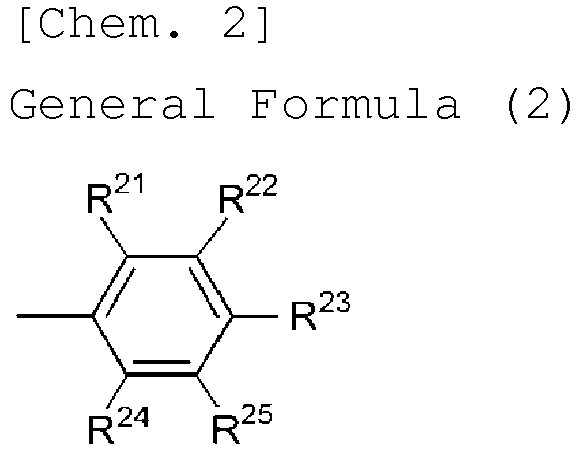
- [9] The organic electroluminescence element according to any one of [1] to [6], wherein at least one of R1, R2, R3, R4, R5, R6, R7 and R8 in the general formula (1) has a structure represented by any of the following general formulae (3) to (5) :


- [10] The organic electroluminescence element according to any one of [1] to [6], wherein at least one of R1, R2, R3, R4, R5, R6, R7 and R8 in the general formula (1) has any of the following structures:

- [11] The organic electroluminescence element according to any one of [1] to [10], wherein at least one of R9, R10, R11, R12, R13, R14, R15 and R16 is a cyano group or has a structure represented by any of the following general formulae (6) to (9):


- [12] The organic electroluminescence element according to any one of [1] to [10], wherein at least one of R9, R10, R11, R12, R13, R14, R15 and R16 in the general formula (1) has any of the following structures:
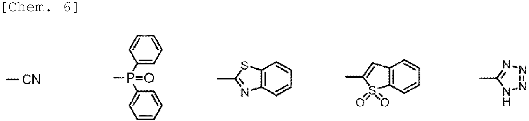
- [13] The organic electroluminescence element according to any one of [1] to [12], wherein the compound represented by the general formula (1) is used as the dopant in the light-emitting layer.
- [14] A compound represented by the following general formula (1'):

- [15] The compound according to [14], wherein Z' in the general formula (1') is a single bond.
- [16] The compound according to [14], wherein Z' in the general formula (1') is a carbonyl group.
- [17] The compound according to [14], wherein Z' in the general formula (1') is >C=C(CN)2.
- [18] The compound according to any one of [14] to [17], wherein R17' in the general formula (1') is an aryl group.
- [19] The compound according to any one of [14] to [17], wherein at least one of R1', R2', R3', R4', R5', R6', R7' and R8' in the general formula (1') is an aryl group substituted with an electron-donating group.
- [20] The compound according to any one of [14] to [17], wherein at least one of R1', R2', R3', R4' , R5', R6', R7' and R8' in the general formula (1') has a structure represented by the following general formula (2):

- [21] The compound according to any one of [14] to [17], wherein at least one of R1', R2', R3', R4', R5', R6', R7' and R8' in the general formula (1') has a structure represented by any of the following general formulae (3) to (5):

- [22] The compound according to any one of [14] to [17], wherein at least one of R1', R2', R3', R4', R5', R6', R7' and R8' in the general formula (1') has any of the following structures:

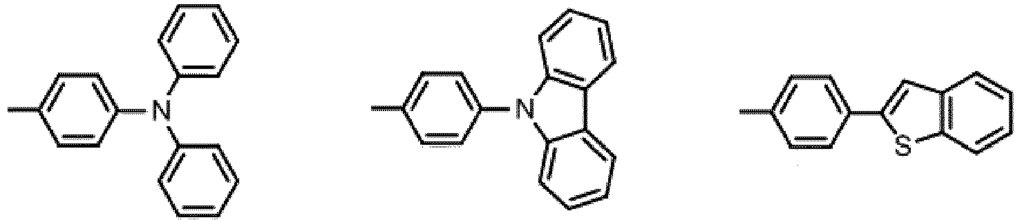
- [23] A delayed fluorescence material comprising a compound represented by the following general formula (1):

- [24] A delayed fluorescence material comprising a compound represented by the following general formula (1'):


- The organic electroluminescence element of the invention exhibits a high emission efficiency and is inexpensive to provide. The compound of the invention is extremely useful as the light-emitting material for such an organic electroluminescence element.
-
- [
Fig. 1 ] This is a schematic cross-sectional view showing a layer configuration of the organic electroluminescence element of Example 1. - [
Fig. 2 ] This is a photoluminescence spectrum in Example 1. - [
Fig. 3 ] This is a graph showing the PL transient decay in Example 1. - [
Fig. 4 ] This is an electroluminescence (EL) spectrum of the organic electroluminescence element of Example 1. - [
Fig. 5 ] This is a graph showing the current density-voltage characteristic-luminance characteristic of the organic electroluminescence element of Example 1. - [
Fig. 6 ] This is a graph showing the external quantum efficiency-current density characteristic of the organic electroluminescence element of Example 1. - [
Fig. 7 ] This is a photoluminescence spectrum in Example 141. - [
Fig. 8 ] This is a graph showing the PL transient decay in Example 141. - [
Fig. 9 ] This is an electroluminescence (EL) spectrum of the organic electroluminescence element of Example 141. - [
Fig. 10 ] This is a graph showing the current density-voltage characteristic-luminance characteristic of the organic electroluminescence element of Example 141. - [
Fig. 11 ] This is a graph showing the external quantum efficiency-current density characteristic of the organic electroluminescence element of Example 141. - The contents of the invention are described in detail hereinunder. The description of the constitutive elements of the invention given hereinunder is for some typical embodiments and specific examples of the invention; however, the invention should not be limited to such embodiments and specific examples. In this description, the numerical range expressed by the wording "a number to another number" means the range that falls between the former number indicating the lower limit of the range and the latter number indicating the upper limit thereof.
- [Compound Represented by General Formula (1)]
- The organic electroluminescence element of the invention contains a compound represented by the following general formula (1) in the light-emitting layer therein. The compound represented by the general formula (1) is first described.

- In the general formula (1), R1, R2, R3, R4, R5, R6, R7, R8 and R17 each independently represent a hydrogen atom or an electron-donating group, and at least one of these is an electron-donating group. When two or more of these are electron-donating groups, those two or more electron-donating groups may be the same or different. Preferably, they are the same. Of R1, R2, R3, R4, R5, R6, R7 and R8 and R17, preferably, any of R2, R3, R4, R5, R6, R7 and R17 is an electron-donating group, and more preferably, any of R2, R3, R6, R7 and R17 is an electron-donating group. Even more preferably, R17 is an electron-donating group, or any one or two of R2, R3, R6 and R7 each are an electron-donating group. In case where two of those are electron-donating groups, preferably, any one of R2 and R3 and any one of R6 and R7 each are an electron-donating group.
- The electron-donating group represented by R1, R2, R3, R4, R5, R6, R7, R8 and R17 is a group which, when bonding to the spiro ring, exhibits a property of donating an electron to the ring. The electron-donating group may be any of an aromatic group, a heteroaromatic group or an aliphatic group, or may be a composite group formed of two or more of these groups. Examples of the electron-donating group include an alkyl group (which may be any of a linear, branched or cyclic group, preferably having from 1 to 6 carbon atoms, more preferably from 1 to 3 carbon atoms, and concretely includes a methyl group, an ethyl group, a propyl group, a pentyl group, a hexyl group, an isopropyl group), an alkoxy group (which may be any of a linear, branched or cyclic group, preferably having from 1 to 6 carbon atoms, more preferably from 1 to 3 carbon atoms, and concretely includes a methoxy group), an amino group or a substituted amino group (preferably an amino group substituted with an aromatic group, concretely including a diphenylamino group, an anilyl group, a tolylamino group), an aryl group (which may be a single ring or a fused ring and may be further substituted with an aryl group, concretely including a phenyl group, a biphenyl group, a terphenyl group), an electron-donating group that contains a heterocyclic structure (preferably an electron-donating group that contains a heterocyclic structure containing a nitrogen atom or a sulfur atom, concretely including a thiophenyl group, a benzothiophenyl group, a julolidyl group, a pyrrolyl group, an indolyl group, a carbazolyl group), etc. Preferably, for example, the electron-donating group has a σp value of at most -0.06, more preferably at most -0.14, even more preferably at most -0.28.
- Of those, preferably, R1, R2, R3, R4, R5, R6, R7 and R8 each are a hydrogen atom or an aryl group substituted with an electron-donating group. The aryl group may comprise one aromatic ring or may have a fused structure of two or more aromatic rings. Preferably, the carbon number of the aryl group is from 6 to 22, more preferably from 6 to 18, even more preferably from 6 to 14, still more preferably from 6 to 10 (i.e., a phenyl group, a 1-naphthyl group, a 2-naphthyl group), most preferably a phenyl group. The electron-donating group to be a substituent on the aryl group is preferably one having the above-mentioned σp value.
- More preferably, R1, R2, R3, R4, R5, R6, R7 and R8 each are a hydrogen atom or a group represented by the following general formula (2):

- In the general formula (2), R21, R22, R23, R24 and R25 each independently represent a hydrogen atom or an electron-donating group, and at least one of these is an electron-donating group. The electron-donating group is preferably one having the above-mentioned σp value. Among R21, R22, R23, R24 and R25, preferably, R22 and R24 each are an electron-donating group, or R23 is an electron-donating group, and more preferably, R23 is an electron-donating group.
- More preferably, R1, R2, R3, R4, R5, R6, R7 and R8 each are a hydrogen atom or have a structure represented by any of the following general formulae (3) to (5):

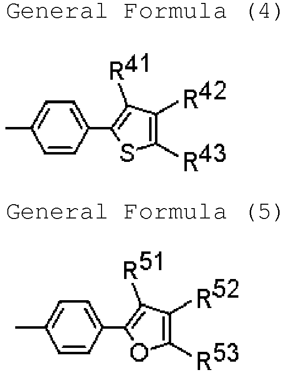
- In the above formulae, R31 and R32 each independently represent a substituted or unsubstituted aryl group; and the aryl group represented by R31 may bond to the aryl group represented by R32. R41, R42 and R43 each independently represent a hydrogen atom, a substituted or unsubstituted alkyl group, or a substituted or unsubstituted aryl group; R41 and R42 may together form a cyclic structure, and R42 and R43 may together form a cyclic structure. R51, R52 and R53 each independently represent a hydrogen atom, a substituted or unsubstituted alkyl group, or a substituted or unsubstituted aryl group; R51 and R52 may together form a cyclic structure, and R52 and R53 may together form a cyclic structure.
- The cyclic structure to be formed together by R41 and R42, by R42 and R43, by R51 and R52, as well as by R52 and R53 may be any of an aromatic ring, a heteroaromatic ring or an aliphatic ring, but is preferably an aromatic ring or a heteroaromatic ring, more preferably an aromatic ring. Specific examples of the cyclic structure include a benzene ring, a naphthalene ring, an anthracene ring, a phenanthrene ring, etc.
- The aryl group as referred to in this description may comprise one aromatic ring or may have a fused structure of two or more aromatic rings. Preferably, the carbon number of the aryl group is from 6 to 22, more preferably from 6 to 18, even more preferably from 6 to 14, still more preferably from 6 to 10 (i.e., a phenyl group, a 1-naphthyl group, a 2-naphthyl group).
- The alkyl group as referred to in this description may be linear, branched or cyclic. Preferred is a linear or branched alkyl group. The carbon number of the alkyl group is preferably from 1 to 20, more preferably from 1 to 12, even more preferably from 1 to 6, still more preferably from 1 to 3 (i.e., a methyl group, an ethyl group, an n-propyl group, an isopropyl group). The cyclic alkyl group includes, for example, a cyclopentyl group, a cyclohexyl group, a cycloheptyl group.
- The substituent for the aryl group and the alkyl group includes an alkyl group, an aryl group, an alkoxy group, an aryloxy group. The description and the preferred range of the alkyl group and the aryl group that may be employed here as the substituent are the same as mentioned above. The alkoxy group that may be employed as the substituent may be linear, branched or cyclic. Preferred is a linear or branched alkoxy group. The carbon number of the alkoxy group is preferably from 1 to 20, more preferably from 1 to 12, even more preferably from 1 to 6, still more preferably from 1 to 3 (i.e., a methoxy group, an ethoxy group, an n-propoxy group, an isopropoxy group). The cyclic alkoxy group includes, for example, a cyclopentyloxy group, a cyclohexyloxy group, a cycloheptyloxy group. The aryloxy group that may be employed here as the substituent may comprise one aromatic ring or may have a fused structure of two or more aromatic rings. The carbon number of the aryloxy group is preferably from 6 to 22, more preferably from 6 to 18, even more preferably from 6 to 14, still more preferably from 6 to 10 (i.e., a phenyloxy group, a 1-naphthyloxy group, a 2-naphthyloxy group).
- As the substituent for the alkyl group and the aryl group in the general formulae (3) to (5), further mentioned is an electron-donating group.
- Preferred examples of the electron-donating group to be represented by R1, R2, R3, R4, R5, R6, R7 and R8 are mentioned below. However, the electron-donating group that may be employed in the general formula (1) should not be limitatively interpreted by these specific examples.

- R9, R10, R11, R12, R13, R14, R15 and R16 in the general formula (1) each independently represent a hydrogen atom, or an electron-withdrawing group that does not have an unshared electron pair at the α-position thereof. However, when Z is a single bond, then at least one of these is an electron-withdrawing group that does not have an unshared electron pair at the α-position thereof. When two or more of these each are an electron-withdrawing group, the two or more electron-withdrawing groups may be the same or different. Preferably, they are the same. Of R9, R10, R11, R12, R13, R14, R15 and R16, preferably, any of R10, R11, R12, R13, R14 and R15 is an electron-withdrawing group, more preferably any of R10, R11, R14 and R15 is an electron-withdrawing group. Even more preferably, one or two of R10, R11, R14 and R15 each are an electron-withdrawing group. When two are electron-withdrawing groups, preferably, any one of R10 and R11 and any one of R14 and R15 are electron-withdrawing groups.
- The electron-withdrawing group to be represented by R9, R10, R11, R12, R13, R14, R15 and R16 in the general formula (1) is a group which, when bonding to the spiro ring, exhibits a property of withdrawing an electron from the spiro ring. However, an electron-withdrawing group that has an unshared electron pair at the α-position thereof (for example, halogen atom) is excluded here. The electron-withdrawing group may be any of an aromatic group, a heteroaromatic group or an aliphatic group, or may be a composite group formed of two or more of these groups. Examples of the electron-withdrawing group include a nitro group, a perfluoroalkyl group (preferably having from 1 to 6 carbon atoms, more preferably from 1 to 3 carbon atoms, and concretely including a trifluoromethyl group), a sulfonyl group, an electron-withdrawing group that has a heterocyclic structure (preferably an electron-withdrawing group that contains a heterocyclic structure containing a nitrogen atom or a sulfur atom, concretely including an oxadiazolyl group, a benzothiadiazolyl group, a tetrazolyl group, a thiazolyl group, an imidazolyl group, etc.), a phosphine oxide structure-containing group, a cyano group, etc. The family of the electron-withdrawing group includes, for example, those of the examples of the electron-withdrawing group mentioned above except the cyano group. Preferably, the electron-withdrawing group has, for example, a σp value of at least 0.02, more preferably at least 0.34, even more preferably at least 0.62.
- Preferably, at least one of R9, R10, R11, R12, R13, R14, R15 and R16 is a cyano group, or has a structure of any of the following general formulae (6) to (9):


- In the above formulae, R61 and R62 each independently represent a substituted or unsubstituted aryl group. R71 and R72 each independently represent a hydrogen atom, a substituted or unsubstituted alkyl group, or a substituted or unsubstituted aryl group; and R71 and R72 may together form a cyclic structure. R81, R82 and R83 each independently represent a hydrogen atom, a substituted or unsubstituted alkyl group, or a substituted or unsubstituted aryl group; R81 and R82 may together form a cyclic structure, and R82 and R83 may together form a cyclic structure. R91 represents a hydrogen atom, a substituted or unsubstituted alkyl group, or a substituted or unsubstituted aryl group; and Z represents a linking group necessary for forming a heteroaromatic ring. The linking chain of Z may be one comprising carbon atoms alone, or may be one comprising hetero atoms alone, or may be one comprising carbon atoms and hetero atoms in mixture. The hetero atom is preferably a nitrogen atom. Preferably, the linking chain has a 2- to 4-atom length, more preferably a 2- or 3-atom length.
- For the description and the preferred range of the aryl group and the aryl group as referred to herein, referred to are the description and the preferred range of the aryl group and the alkyl group which R41, R42, R43, R51, R52 and R53 may take. However, as the substituent for the aryl group and the alkyl group in the general formulae (6) to (9), there may be additionally mentioned an electron-withdrawing group in addition to the alkyl group, the aryl group, the alkyloxy group and the aryloxy group.
- Preferred examples of the electron-withdrawing group to be represented by R9, R10, R11, R12, R13, R14, R15 and R16 are listed below. However, the electron-withdrawing group that may be employed in the general formula (1) should not be limitatively interpreted by these specific examples.

- R17 in the general formula (1) represents a hydrogen atom or an electron-donating group, and for the electron-donating group of R17, referred to are the description and the preferred range of the electron-donating group for the above-mentioned R1, R2, R3, R4, R5, R6, R7 and R8. However, the electron-donating group of R17 is also preferably an unsubstituted aryl group, and among this, the group is more preferably an unsubstituted phenyl group. The electron-donating group of R17 may be the same as the electron-donating group in R1, R2, R3, R4, R5, R6, R7 and R8.
- In the general formula (1), Z represents a single bond or >C=Y, and Y represents O S, C(CN)2 or C(COOH)2. For example, when Y is O Z in the general formula (1) is a carbonyl group. From the viewpoint of emission efficiency, for example, more preferred are a group of compounds where R17 is an aryl group and Z is a carbonyl group or >C=C(CN)2.
- Of the compounds represented by the above-mentioned general formula (1), those represented by the following general formula (1') are novel compounds.
[Chem. 19]
- In the general formula (1'), R1', R2', R3', R4', R5', R6', R7', R8' and R17' each independently represent a hydrogen atom or an electron-donating group, and at least one of these is an electron-donating group . R9', R10', R11', R12', R13', R14' , R15' and R16' each independently represent a hydrogen atom or a cyano group. Z' represents a single bond or >C=Y, Y represents O, S, C(CN)2 or C (COOH)2. When Z' is a single bond, >C=O or >C=S, then at least one of R9', R10', R11', R12', R13', R14', R15' and R16' is a cyano group.
- For the description and the preferred range of the electron-donating group and the electron-withdrawing group in the general formula (1'), referred to are the corresponding descriptions in the general formula (1) mentioned above.
- The molecular weight of the compound represented by the general formula (1) is, for example, when an organic layer containing the compound is intended to be formed through vapor deposition in use thereof, preferably at most 1500, more preferably at most 1200, even more preferably at most 1000, still more preferably at most 800. The lower limit of the molecular weight may be, for example, at least 350.
- Specific examples of the compound represented by the general formula (1) are shown below. However, the compound represented by the general formula (1) for use in the invention should not be limitatively interpreted by these specific examples. In the Tables, D1 to D3 each represent an aryl group substituted with the above-mentioned electron-donating group; A1 to A5 each represent the above-mentioned electron-withdrawing group; H represents a hydrogen atom; and Ph represents a phenyl group.
[Table 1] Compound No. R2 R7 R10 R15 R17 Z Other R 1 H H A1 A1 Ph single bond H 2 H D1 A1 A1 Ph single bond H 3 H D2 A1 A1 Ph single bond H 4 H D3 A1 A1 Ph single bond H 5 H H A2 A2 Ph single bond H 6 H D1 A2 A2 Ph single bond H 7 H D2 A2 A2 Ph single bond H 8 H D3 A2 A2 Ph single bond H 9 H H A3 A3 Ph single bond H 10 H D1 A3 A3 Ph single bond H 11 H D2 A3 A3 Ph single bond H 12 H D3 A3 A3 Ph single bond H 13 H H A4 A4 Ph single bond H 14 H D1 A4 A4 Ph single bond H 15 H D2 A4 A4 Ph single bond H 16 H D3 A4 A4 Ph single bond H 17 H H A5 A5 Ph single bond H 18 H D1 A5 A5 Ph single bond H 19 H D2 A5 A5 Ph single bond H 20 H D3 A5 A5 Ph single bond H 21 D1 D1 A1 A1 Ph single bond H 22 D2 D2 A1 A1 Ph single bond H 23 D3 D3 A1 A1 Ph single bond H 24 D1 D1 A2 A2 Ph single bond H 25 D2 D2 A2 A2 Ph single bond H 26 D3 D3 A2 A2 Ph single bond H 27 D1 D1 A3 A3 Ph single bond H 28 D2 D2 A3 A3 Ph single bond H 29 D3 D3 A3 A3 Ph single bond H 30 D1 D1 A4 A4 Ph single bond H 31 D2 D2 A4 A4 Ph single bond H 32 D3 D3 A4 A4 Ph single bond H 33 D1 D1 A5 A5 Ph single bond H 34 D2 D2 A5 A5 Ph single bond H 35 D3 D3 A5 A5 Ph single bond H [Table 2] Compound No. R3 R6 R11 R14 R17 Z Other R 36 H H H A1 Ph single bond H 37 H D1 H A1 Ph single bond H 38 H D2 H A1 Ph single bond H 39 H D3 H A1 Ph single bond H 40 H H H A2 Ph single bond H 41 H D1 H A2 Ph single bond H 42 H D2 H A2 Ph single bond H 43 H D3 H A2 Ph single bond H 44 H H H A3 Ph single bond H 45 H D1 H A3 Ph single bond H 46 H D2 H A3 Ph single bond H 47 H D3 H A3 Ph single bond H 48 H H H A4 Ph single bond H 49 H D1 H A4 Ph single bond H 50 H D2 H A4 Ph single bond H 51 H D3 H A4 Ph single bond H 52 H H H A5 Ph single bond H 53 H D1 H A5 Ph single bond H 54 H D2 H A5 Ph single bond H 55 H D3 H A5 Ph single bond H 56 D1 D1 H A1 Ph single bond H 57 D2 D2 H A1 Ph single bond H 58 D3 D3 H A1 Ph single bond H 59 D1 D1 H A2 Ph single bond H 60 D2 D2 H A2 Ph single bond H 61 D3 D3 H A2 Ph single bond H 62 D1 D1 H A3 Ph single bond H 63 D2 D2 H A3 Ph single bond H 64 D3 D3 H A3 Ph single bond H 65 D1 D1 H A4 Ph single bond H 66 D2 D2 H A4 Ph single bond H 67 D3 D3 H A4 Ph single bond H 68 D1 D1 H A5 Ph single bond H 69 D2 D2 H A5 Ph single bond H 70 D3 D3 H A5 Ph single bond H [Table 3] Compound No. R2 R7 R10 R15 R17 Z Other R 71 H H A1 A1 Ph C=O H 72 H D1 A1 A1 Ph C=O H 73 H D2 A1 A1 Ph C=O H 74 H D3 A1 A1 Ph C=O H 75 H H A2 A2 Ph C=O H 76 H D1 A2 A2 Ph C=O H 77 H D2 A2 A2 Ph C=O H 78 H D3 A2 A2 Ph C=O H 79 H H A3 A3 Ph C=O H 80 H D1 A3 A3 Ph C=O H 81 H D2 A3 A3 Ph C=O H 82 H D3 A3 A3 Ph C=O H 83 H H A4 A4 Ph C=O H 84 H D1 A4 A4 Ph C=O H 85 H D2 A4 A4 Ph C=O H 86 H D3 A4 A4 Ph C=O H 87 H H A5 A5 Ph C=O H 88 H D1 A5 A5 Ph C=O H 89 H D2 A5 A5 Ph C=O H 90 H D3 A5 A5 Ph C=O H 91 D1 D1 A1 A1 Ph C=O H 92 D2 D2 A1 A1 Ph C=O H 93 D3 D3 A1 A1 Ph C=O H 94 D1 D1 A2 A2 Ph C=O H 95 D2 D2 A2 A2 Ph C=O H 96 D3 D3 A2 A2 Ph C=O H 97 D1 D1 A3 A3 Ph C=O H 98 D2 D2 A3 A3 Ph C=O H 99 D3 D3 A3 A3 Ph C=O H 100 D1 D1 A4 A4 Ph C=O H 101 D2 D2 A4 A4 Ph C=O H 102 D3 D3 A4 A4 Ph C=O H 103 D1 D1 A5 A5 Ph C=O H 104 D2 D2 A5 A5 Ph C=O H 105 D3 D3 A5 A5 Ph C=O H [Table 4] Compound No. R3 R6 R11 R14 R17 Z Other R 106 H H H A1 Ph C=O H 107 H D1 H A1 Ph C=O H 108 H D2 H A1 Ph C=O H 109 H D3 H A1 Ph C=O H 110 H H H A2 Ph C=O H 111 H D1 H A2 Ph C=O H 112 H D2 H A2 Ph C=O H 113 H D3 H A2 Ph C=O H 114 H H H A3 Ph C=O H 115 H D1 H A3 Ph C=O H 116 H D2 H A3 Ph C=O H 117 H D3 H A3 Ph C=O H 118 H H H A4 Ph C=O H 119 H D1 H A4 Ph C=O H 120 H D2 H A4 Ph C=O H 121 H D3 H A4 Ph C=O H 122 H H H A5 Ph C=O H 123 H D1 H A5 Ph C=O H 124 H D2 H A5 Ph C=O H 125 H D3 H A5 Ph C=O H 126 D1 D1 H A1 Ph C=O H 127 D2 D2 H A1 Ph C=O H 128 D3 D3 H A1 Ph C=O H 129 D1 D1 H A2 Ph C=O H 130 D2 D2 H A2 Ph C=O H 131 D3 D3 H A2 Ph C=O H 132 D1 D1 H A3 Ph C=O H 133 D2 D2 H A3 Ph C=O H 134 D3 D3 H A3 Ph C=O H 135 D1 D1 H A4 Ph C=O H 136 D2 D2 H A4 Ph C=O H 137 D3 D3 H A4 Ph C=O H 138 D1 D1 H A5 Ph C=O H 139 D2 D2 H A5 Ph C=O H 140 D3 D3 H A5 Ph C=O H 141 H H H H Ph C=O H [Table 5] Compound No. R2 R7 R10 R15 R17 Z Other R 142 H H A1 A1 Ph C=S H 143 H D1 A1 A1 Ph C=S H 144 H D2 A1 A1 Ph C=S H 145 H D3 A1 A1 Ph C=S H 146 H H A2 A2 Ph C=S H 147 H D1 A2 A2 Ph C=S H 148 H D2 A2 A2 Ph C=S H 149 H D3 A2 A2 Ph C=S H 150 H H A3 A3 Ph C=S H 151 H D1 A3 A3 Ph C=S H 152 H D2 A3 A3 Ph C=S H 153 H D3 A3 A3 Ph C=S H 154 H H A4 A4 Ph C=S H 155 H D1 A4 A4 Ph C=S H 156 H D2 A4 A4 Ph C=S H 157 H D3 A4 A4 Ph C=S H 158 H H A5 A5 Ph C=S H 159 H D1 A5 A5 Ph C=S H 160 H D2 A5 A5 Ph C=S H 161 H D3 A5 A5 Ph C=S H 162 D1 D1 A1 A1 Ph C=S H 163 D2 D2 A1 A1 Ph C=S H 164 D3 D3 A1 A1 Ph C=S H 165 D1 D1 A2 A2 Ph C=S H 166 D2 D2 A2 A2 Ph C=S H 167 D3 D3 A2 A2 Ph C=S H 168 D1 D1 A3 A3 Ph C=S H 169 D2 D2 A3 A3 Ph C=S H 170 D3 D3 A3 A3 Ph C=S H 171 D1 D1 A4 A4 Ph C=S H 172 D2 D2 A4 A4 Ph C=S H 173 D3 D3 A4 A4 Ph C=S H 174 D1 D1 A5 A5 Ph C=S H 175 D2 D2 A5 A5 Ph C=S H 176 D3 D3 A5 A5 Ph C=S H [Table 6] Compound No. R3 R6 R11 R14 R17 Z Other R 177 H H H A1 Ph C=S H 178 H D1 H A1 Ph C=S H 179 H D2 H A1 Ph C=S H 180 H D3 H A1 Ph C=S H 181 H H H A2 Ph C=S H 182 H D1 H A2 Ph C=S H 183 H D2 H A2 Ph C=S H 184 H D3 H A2 Ph C=S H 185 H H H A3 Ph C=S H 186 H D1 H A3 Ph C=S H 187 H D2 H A3 Ph C=S H 188 H D3 H A3 Ph C=S H 189 H H H A4 Ph C=S H 190 H D1 H A4 Ph C=S H 191 H D2 H A4 Ph C=S H 192 H D3 H A4 Ph C=S H 193 H H H A5 Ph C=S H 194 H D1 H A5 Ph C=S H 195 H D2 H A5 Ph C=S H 196 H D3 H A5 Ph C=S H 197 D1 D1 H A1 Ph C=S H 198 D2 D2 H A1 Ph C=S H 199 D3 D3 H A1 Ph C=S H 200 D1 D1 H A2 Ph C=S H 201 D2 D2 H A2 Ph C=S H 202 D3 D3 H A2 Ph C=S H 203 D1 D1 H A3 Ph C=S H 204 D2 D2 H A3 Ph C=S H 205 D3 D3 H A3 Ph C=S H 206 D1 D1 H A4 Ph C=S H 207 D2 D2 H A4 Ph C=S H 208 D3 D3 H A4 Ph C=S H 209 D1 D1 H A5 Ph C=S H 210 D2 D2 H A5 Ph C=S H 211 D3 D3 H A5 Ph C=S H 212 H H H H Ph C=S H [Table 7] Compound No. R2 R7 R10 R15 R17 Z Other R 213 H H A1 A1 Ph C=C(CN)2 H 214 H D1 A1 A1 Ph C=C(CN)2 H 215 H D2 A1 A1 Ph C=C(CN)2 H 216 H D3 A1 A1 Ph C=C(CN)2 H 217 H H A2 A2 Ph C=C(CN)2 H 218 H D1 A2 A2 Ph C=C(CN)2 H 219 H D2 A2 A2 Ph C=C(CN)2 H 220 H D3 A2 A2 Ph C=C(CN)2 H 221 H H A3 A3 Ph C=C(CN)2 H 222 H D1 A3 A3 Ph C=C(CN)2 H 223 H D2 A3 A3 Ph C=C(CN)2 H 224 H D3 A3 A3 Ph C=C(CN)2 H 225 H H A4 A4 Ph C=C(CN)2 H 226 H D1 A4 A4 Ph C=C(CN)2 H 227 H D2 A4 A4 Ph C=C(CN)2 H 228 H D3 A4 A4 Ph C=C(CN)2 H 229 H H A5 A5 Ph C=C(CN)2 H 230 H D1 A5 A5 Ph C=C(CN)2 H 231 H D2 A5 A5 Ph C=C(CN)2 H 232 H D3 A5 A5 Ph C=C(CN)2 H 233 D1 D1 A1 A1 Ph C=C(CN)2 H 234 D2 D2 A1 A1 Ph C=C(CN)2 H 235 D3 D3 A1 A1 Ph C=C(CN)2 H 236 D1 D1 A2 A2 Ph C=C(CN)2 H 237 D2 D2 A2 A2 Ph C=C(CN)2 H 238 D3 D3 A2 A2 Ph C=C(CN)2 H 239 D1 D1 A3 A3 Ph C=C(CN)2 H 240 D2 D2 A3 A3 Ph C=C(CN)2 H 241 D3 D3 A3 A3 Ph C=C(CN)2 H 242 D1 D1 A4 A4 Ph C=C(CN)2 H 243 D2 D2 A4 A4 Ph C=C(CN)2 H 244 D3 D3 A4 A4 Ph C=C(CN)2 H 245 D1 D1 A5 A5 Ph C=C(CN)2 H 246 D2 D2 A5 A5 Ph C=C(CN)2 H 247 D3 D3 A5 A5 Ph C=C(CN)2 H [Table 8] Compound No. R3 R6 R11 R14 R17 Z Other R 248 H H H A1 Ph C=C(CN)2 H 249 H D1 H A1 Ph C=C(CN)2 H 250 H D2 H A1 Ph C=C(CN)2 H 251 H D3 H A1 Ph C=C(CN)2 H 252 H H H A2 Ph C=C(CN)2 H 253 H D1 H A2 Ph C=C(CN)2 H 254 H D2 H A2 Ph C=C(CN)2 H 255 H D3 H A2 Ph C=C(CN)2 H 256 H H H A3 Ph C=C(CN)2 H 257 H D1 H A3 Ph C=C(CN)2 H 258 H D2 H A3 Ph C=C(CN)2 H 259 H D3 H A3 Ph C=C(CN)2 H 260 H H H A4 Ph C=C(CN)2 H 261 H D1 H A4 Ph C=C(CN)2 H 262 H D2 H A4 Ph C=C(CN)2 H 263 H D3 H A4 Ph C=C(CN)2 H 264 H H H A5 Ph C=C(CN)2 H 265 H D1 H A5 Ph C=C(CN)2 H 266 H D2 H A5 Ph C=C(CN)2 H 267 H D3 H A5 Ph C=C(CN)2 H 268 D1 D1 H A1 Ph C=C(CN)2 H 269 D2 D2 H A1 Ph C=C(CN)2 H 270 D3 D3 H A1 Ph C=C(CN)2 H 271 D1 D1 H A2 Ph C=C(CN)2 H 272 D2 D2 H A2 Ph C=C(CN)2 H 273 D3 D3 H A2 Ph C=C(CN)2 H 274 D1 D1 H A3 Ph C=C(CN)2 H 275 D2 D2 H A3 Ph C=C(CN)2 H 276 D3 D3 H A3 Ph C=C(CN)2 H 277 D1 D1 H A4 Ph C=C(CN)2 H 278 D2 D2 H A4 Ph C=C(CN)2 H 279 D3 D3 H A4 Ph C=C(CN)2 H 280 D1 D1 H A5 Ph C=C(CN)2 H 281 D2 D2 H A5 Ph C=C(CN)2 H 282 D3 D3 H A5 Ph C=C(CN)2 H 283 H H H H Ph C=C(CN)2 H [Table 9] Compound No. R2 R7 R10 R15 R17 Z Other R 284 H H A1 A1 Ph C=C(COOH)2 H 285 H D1 A1 A1 Ph C=C(COOH)2 H 286 H D2 A1 A1 Ph C=C(COOH)2 H 287 H D3 A1 A1 Ph C=C(COOH)2 H 288 H H A2 A2 Ph C=C(COOH)2 H 289 H D1 A2 A2 Ph C=C(COOH)2 H 290 H D2 A2 A2 Ph C=C(COOH)2 H 291 H D3 A2 A2 Ph C=C(COOH)2 H 292 H H A3 A3 Ph C=C(COOH)2 H 293 H D1 A3 A3 Ph C=C(COOH)2 H 294 H D2 A3 A3 Ph C=C(COOH)2 H 295 H D3 A3 A3 Ph C=C(COOH)2 H 296 H H A4 A4 Ph C=C(COOH)2 H 297 H D1 A4 A4 Ph C=C(COOH)2 H 298 H D2 A4 A4 Ph C=C(COOH)2 H 299 H D3 A4 A4 Ph C=C(COOH)2 H 300 H H A5 A5 Ph C=C(COOH)2 H 301 H D1 A5 A5 Ph C=C(COOH)2 H 302 H D2 A5 A5 Ph C=C(COOH)2 H 303 H D3 A5 A5 Ph C=C(COOH)2 H 304 D1 D1 A1 A1 Ph C=C(COOH)2 H 305 D2 D2 A1 A1 Ph C=C(COOH)2 H 306 D3 D3 A1 A1 Ph C=C(COOH)2 H 307 D1 D1 A2 A2 Ph C=C(COOH)2 H 308 D2 D2 A2 A2 Ph C=C(COOH)2 H 309 D3 D3 A2 A2 Ph C=C(COOH)2 H 310 D1 D1 A3 A3 Ph C=C(COOH)2 H 311 D2 D2 A3 A3 Ph C=C(COOH)2 H 312 D3 D3 A3 A3 Ph C=C(COOH)2 H 313 D1 D1 A4 A4 Ph C=C(COOH)2 H 314 D2 D2 A4 A4 Ph C=C(COOH)2 H 315 D3 D3 A4 A4 Ph C=C(COOH)2 H 316 D1 D1 A5 A5 Ph C=C(COOH)2 H 317 D2 D2 A5 A5 Ph C=C(COOH)2 H 318 D3 D3 A5 A5 Ph C=C(COOH)2 H [Table 10] Compound No. R3 R6 R11 R14 R17 Z Other R 319 H H H A1 Ph C=C(COOH)2 H 320 H D1 H A1 Ph C=C(COOH)2 H 321 H D2 H A1 Ph C=C(COOH)2 H 322 H D3 H A1 Ph C=C(COOH)2 H 323 H H H A2 Ph C=C(COOH)2 H 324 H D1 H A2 Ph C=C(COOH)2 H 325 H D2 H A2 Ph C=C(COOH)2 H 326 H D3 H A2 Ph C=C(COOH)2 H 327 H H H A3 Ph C=C(COOH)2 H 328 H D1 H A3 Ph C=C(COOH)2 H 329 H D2 H A3 Ph C=C(COOH)2 H 330 H D3 H A3 Ph C=C(COOH)2 H 331 H H H A4 Ph C=C(COOH)2 H 332 H D1 H A4 Ph C=C(COOH)2 H 333 H D2 H A4 Ph C=C(COOH)2 H 334 H D3 H A4 Ph C=C(COOH)2 H 335 H H H A5 Ph C=C(COOH)2 H 336 H D1 H A5 Ph C=C(COOH)2 H 337 H D2 H A5 Ph C=C(COOH)2 H 338 H D3 H A5 Ph C=C(COOH)2 H 339 D1 D1 H A1 Ph C=C(COOH)2 H 340 D2 D2 H A1 Ph C=C(COOH)2 H 341 D3 D3 H A1 Ph C=C(COOH)2 H 342 D1 D1 H A2 Ph C=C(COOH)2 H 343 D2 D2 H A2 Ph C=C(COOH)2 H 344 D3 D3 H A2 Ph C=C(COOH)2 H 345 D1 D1 H A3 Ph C=C(COOH)2 H 346 D2 D2 H A3 Ph C=C(COOH)2 H 347 D3 D3 H A3 Ph C=C(COOH)2 H 348 D1 D1 H A4 Ph C=C(COOH)2 H 349 D2 D2 H A4 Ph C=C(COOH)2 H 350 D3 D3 H A4 Ph C=C(COOH)2 H 351 D1 D1 H A5 Ph C=C(COOH)2 H 352 D2 D2 H A5 Ph C=C(COOH)2 H 353 D3 D3 H A5 Ph C=C(COOH)2 H 354 H H H H Ph C=C(COOH)2 H - The production method for the compounds represented by the general formula (1) is not specifically defined. The compounds represented by the general formula (1) may be produced by suitably combining known production methods and conditions.
- For example, one preferred production method is represented by the scheme mentioned below. Here as one typical example, a production method for a compound represented by a general formula (15) is described, in which the acridine structure is substituted with one electron-donating group D, the nitrogen atom of the acridine structure is substituted with R17, and the fluorene structure is substituted with one electron-withdrawing group A.

- In the above scheme, first the halogen-substituted diphenylamine represented by the general formula (11) is reacted with n-butyllithium, and then further reacted with the fluorene represented by the general formula (12). Acetic acid and concentrated hydrochloric acid are added to the fluorene derivative obtained through the previous reaction and represented by the general formula (13), and heated for cyclization to give the intended product represented by the general formula (14). X in the general formula (11) represents a halogen atom. Concretely, X includes a fluorine atom, a chlorine atom, a bromine atom and an iodine atom, and is preferably a chlorine atom, a bromine atom or an iodine atom, more preferably a bromine atom. In the general formulae (11), (13) and (14), D represents an electron-donating group; and in the general formulae (12), (13) and (14), A represents an electron-withdrawing group. In the coupling reaction of the first step and the cyclization of the second step, employable are reaction conditions generally used in the same type of the coupling reaction and the cyclization.
- Regarding the production methods for the compounds represented by the general formula (1) except the general formula (14), those compounds may be produced in accordance with the method of the above scheme. For example, of the compounds represented by the general formula (1), those having an anthrone structure may be produced in the same manner as above but using an anthraquinone (anthracene-9,10-quinone) substituted with the electron-withdrawing group A in place of the compound represented by the general formula (12) in the above scheme. Depending on the type of the electron-donating group D and the type of the electron-withdrawing group A to be introduced into the spiro ring, reaction specific to the substituents may be utilized here. For example, in case where a cyano group is introduced as the electron-withdrawing group, a spiro compound substituted with a halogen atom at the position at which the cyano group is to be introduced is first prepared, and then the compound is reacted with CuCN at the halogen atom whereby the halogen atom may be converted into the cyano group.
- For the details of the reaction, referred to are Synthesis Examples to be given hereinunder. The compounds represented by the general formula (1) may also be produced by combining any other known reactions.
- The organic electroluminescence element of the invention is provided with a configuration having an anode, a cathode and an organic layer between the anode and the cathode. The organic layer contains at least a light-emitting layer, and may be a light-emitting layer alone or may have any one or more organic layers in addition to a light-emitting layer. The organic electroluminescence element of the invention contains the compound represented by the general formula (1) in the light-emitting layer therein.
- When the compound represented by the general formula (1) is used in the light-emitting layer of an organic electroluminescence element as a thermally-activated delayed fluorescence material, then the element secures a high emission efficiency more inexpensively than before. Heretofore, for producing an organic electroluminescence element having a high emission efficiency, there have been actively made studies using a phosphorescence material having a high exciton production efficiency. However, using a phosphorescence material has a problem in that the cost is high as requiring use of a rare metal such as Ir or Pt. Using a delayed fluorescence material does not require such an expensive material, therefore making it possible to inexpensively provide an organic electroluminescence element having a high emission efficiency.
- The organic electroluminescence element of the invention has a laminate configuration of at least an anode, an organic layer and a cathode. A single-layer organic electroluminescence element may comprise a light-emitting layer alone between the anode and the cathode; however, it is desirable that the organic electroluminescence element of the invention is provided with multiple organic layers. The other organic layers than the light-emitting layer may be referred to as a hole injection layer, a hole transport layer, an electron blocking layer, a light-emitting layer, a hole blocking layer, an electron transport layer, an electron injection layer or the like, depending on the functions thereof, for which any known material may be used as suitably combined. As specific configuration examples including an anode and a cathode, there may be mentioned anode/light-emitting layer/cathode, anode/hole injection layer/light-emitting layer/cathode, anode/hole injection layer/hole transport layer/light-emitting layer/cathode, anode/hole injection layer/light-emitting layer/electron injection layer/cathode, anode/hole injection layer/hole transport layer/light-emitting layer/electron injection layer/cathode, anode/hole injection layer/light-emitting layer/electron transport layer/electron injection layer/cathode, anode/hole injection layer/hole transport layer/light-emitting layer/electron transport layer/electron injection layer/cathode, anode/light-emitting layer/electron injection layer/cathode, anode/light-emitting layer/electron injection layer/electron transport layer/cathode, anode/hole injection layer/light-emitting layer/hole blocking layer/electron injection layer/cathode. The configuration of anode/organic layer/cathode may be formed on a substrate. The configurations that may be employed in the invention should not be limited to those exemplifications. Especially preferably, the compound represented by the general formula (1) is used in the light-emitting layer, which, however, does not exclude use of the compound represented by the general formula (1) in the other organic layer than the light-emitting layer as a charge transport material or the like therein.
- In producing the organic layers and the electrodes that constitute the organic electroluminescence element of the invention, any known production methods may be employed as suitably selected. In addition, various materials generally employed in known organic electroluminescence elements can be selected and used in those organic layers and electrodes. Further, various modifications of known techniques and those that may be readily anticipated from known techniques may be optionally applied to the organic electroluminescence element of the invention. Typical materials of constituting the organic electroluminescence element of the invention are described below; however, the materials usable for the organic electroluminescence element of the invention should not be limitatively interpreted by the following description.
- The substrate functions as a support of supporting the configuration of anode/organic layer/cathode and further functions as a substrate in producing the configuration of anode/organic layer/cathode. The substrate may be formed of a transparent material, or may also be formed of a semitransparent or nontransparent material. In case where emitted light is taken out from the side of the anode, a transparent substrate is preferably used. The material to constitute the substrate includes glass, quartz, metal, polycarbonate, polyester, polymethacrylate, polysulfone. When a flexible substrate is sued, then there may be provided a flexible organic electroluminescence element.
- The anode has a function of injecting holes toward the organic layer. As the anode, preferably used is a material having a high work function. For example, a material having a work function of at least 4 eV is preferably used. Concretely, there are mentioned metals (for example, aluminium, gold, silver, nickel, palladium, platinum), metal oxides (for example, indium oxide, tin oxide, zinc oxide, mixture of indium oxide and tin oxide [ITO], mixture of zinc oxide and indium oxide [IZO]), metal halides (for example, copper iodide), carbon black. In addition, also employable are electroconductive polymers such as polyaniline, poly(3-methylthiophene), polypyrrole, etc. In case where emitted light is taken out from the side of the anode, preferred is use of a material having a high light transmittance for the emitted light, such as ITO, IZO or the like. The transmittance is preferably at least 10%, more preferably at least 50%, even more preferably at least 80%. The thickness of the anode is generally at least 3 nm, but preferably at least 10 nm. The upper limit may be, for example, at most 1 µm, however, when the anode is not required to have transparency, the thickness thereof may be further larger, and for example, such a thick anode may additionally serve also as the above-mentioned substrate. The anode may be formed, for example, according to a vapor deposition method, a sputtering method, or a coating method. In case where an electroconductive polymer is used for the anode, the anode may be formed on the substrate according to an electrolytic polymerization method. After the anode formation, the surface may be processed for the purpose of improving the hole injection function thereof. Specific examples of the surface treatment include plasma treatment (for example, argon plasma treatment, oxygen plasma treatment), UV treatment, ozone treatment, etc.
- The hole injection layer has a function of transporting holes from the anode to the side of the light-emitting layer. The hole injection layer is formed generally on the anode, and therefore the layer is preferably excellent in the adhesiveness to the anode surface. Consequently, it is desirable that the layer is formed of a material having good thin-film formability. The hole transport layer has a function of transporting holes to the side of the light-emitting layer. The hole transport layer is formed of a material having excellent hole transportability.
- For the hole injection layer and the hole transport layer, used are hole transport materials having a high hole mobility and a small ionization energy. The ionization energy of the material is, for example, preferably from 4.5 to 6.0 eV. As the hole transport material, various materials that are said to be usable as the hole injection layer or the hole transport layer of organic electroluminescence elements may be used here as suitably selected. The hole transport material may be a polymer material having a recurring unit or may also be a low-molecular compound.
- As the hole transport material, for example, there may be mentioned aromatic tertiary amine compounds, styrylamine compounds, oxadiazole derivatives, imidazole derivatives, triazole derivatives, pyrazoline derivatives, pyrazolone derivatives, phenylenediamine derivatives, arylamine derivatives, amino-substituted chalcone derivatives, oxazole derivatives, polyarylalkane derivatives, styrylanthracene derivatives, fluorenone derivatives, hydrazone derivatives, stilbene derivatives, silazane derivatives, silane polymers, aniline copolymers, thiophene polymers, porphyrin compounds.
- As a preferred hole transport material, there are mentioned aromatic tertiary amine compounds, concretely including triphenylamine, tritolylamine, N,N'-diphenyl-N,N'-(3-methylphenyl)-1,1'-biphenyl-4,4'-diam ine, N,N,N',N'-(4-methylphenyl)-1,1'-phenyl-4,4'-diamine, N,N,N',N'-(4-methylphenyl)-1,1'-biphenyl-4,4'-diamine, N,N'-diphenyl-N,N'-dinaphthyl-1,1'-biphenyl-4,4'-diamine, N,N'-(methylphenyl)-N,N'-(4-n-butylphenyl)-phenanthrene-9,1 0-diamine, N,N-bis(4-di-4-tolylaminophenyl)-4-phenyl-cyclohexane, N,N'-bis(4'-diphenylamino-4-biphenylyl)-N,N'-diphenylbenzid ine, N,N'-bis(4'-diphenylamino-4-phenyl)-N,N'-diphenylbenzidine, N,N'-bis(4'-diphenylamino-4-phenyl)-N,N'-di(1-naphthyl)benz idine, N,N'-bis(4'-phenyl(1-naphthyl)amino-4-phenyl)-N,N'-diphenyl benzidine, N,N'-bis(4'-phenyl(1-naphthyl)amino-4-phenyl)-N,N'-di(1-nap hthyl)benzidine, etc. Also as a preferred hole transport material, phthalocyanine compounds are mentioned. Concretely, there are mentioned H2Pc, CuPc, CoPc, NiPc, ZnPc, PdPc, FePc, MnPc, ClAlPc, ClGaPc, ClInPc, ClSnPc, Cl2SiPc, (HO)AlPc, (HO)GaPc, VOPc, TiOPc, MoOPc, GaPc-O-GaPc [Pc means phthalocyanine]. Further, also preferred is use of poly(ethylenedioxy)thiophene (PEDOT), metal oxides such as molybdenum oxide and the like, and known aniline derivatives.
- One alone or two or more different types of hole transport materials may be used in one layer, either singly or as combined therein. The hole injection layer and the hole transport layer may be formed, for example, according to a vapor deposition method, a sputtering method or a coating method. The thickness of the hole injection layer and the hole transport layer may be generally at least 3 nm each but preferably at least 10 nm each. The upper limit may be, for example, at most 5 µm each.
- The light-emitting layer in the organic electroluminescence element of the invention may contain a host material and a dopant material, or may be formed of a single material. The light-emitting layer in the organic electroluminescence element of the invention contains the compound represented by the general formula (1).
- When the light-emitting layer contains a host material and a dopant material, preferably, the amount of the dopant material is at most 10% by weight of the host material therein for the purpose of preventing concentration quenching, more preferably at most 6% by weight. One material alone or two or more different types of materials may be used either singly or as combined for the dopant material and the host material. The doping may be attained by co-deposition of the host material and the dopant material, in which the host material and the dopant material may be previously mixed for simultaneous vapor deposition.
- As the host material for use in the light-emitting layer, there are mentioned carbazole derivatives, quinolinol derivative metal complexes, oxadiazole derivatives, distyrylarylene derivatives, diphenylanthracene derivatives, etc. In addition to these, also usable here are those that are proposed as the host material in a light-emitting layer, as suitably selected. As a preferred host material, for example, there are mentioned the compounds represented by the following general formula (10) :

- In the general formula (10), Z represents a q-valent linking group; and q indicates an integer of from 2 to 4. R101 and R102 each independently represent a substituent; and n101 and n102 each independently indicate an integer of from 0 to 4. When n101 is an integer of from 2 to 4, n101's R101's may be the same or different; and when n102 is an integer of from 2 to 4, n102's R102's may be the same or different. Further, R101, R102, n101 and n102 in q's constitutive elements may be the same or different.
- As the substituent represented by R101 and R102 in the general formula (10) includes, for example, a substituted or unsubstituted alkyl group, a substituted or unsubstituted alkoxy group, a substituted or unsubstituted aryl group, a substituted or unsubstituted aryloxy group, a substituted or unsubstituted alkenyl group, a substituted or unsubstituted amino group, a halogen atom, a cyano group. Preferred are a substituted or unsubstituted alkyl group, a substituted or unsubstituted aryl group, a substituted or unsubstituted alkoxy group, a substituted or unsubstituted aryloxy group; and more preferred are a substituted or unsubstituted alkyl group, a substituted or unsubstituted aryl group.
- Preferably, n101 and n102 each are independently an integer of from 0 to 3, more preferably an integer of from 0 to 2. Also preferably, both n101 and n102 are 0.
- Z in the general formula (10) is preferably a linking group that contains an aromatic ring or a hetero ring. The aromatic ring may be a single ring or a fused ring of two or more aromatic rings fused together. The carbon number of the aromatic ring is preferably from 6 to 22, more preferably from 6 to 18, even more preferably from 6 to 14, still more preferably from 6 to 10. Specific examples of the aromatic ring include a benzene ring and a naphthalene ring. The hetero ring may be a single ring, or a fused ring of one or more hetero ring fused with an aromatic ring or a hetero ring. The carbon number of the hetero ring is preferably from 5 to 22, more preferably from 5 to 18, even more preferably from 5 to 14, still more preferably from 5 to 10. Preferably, the hetero atom to constitute the hetero ring is a nitrogen atom. Specific examples of the hetero ring include a pyridine ring, a pyridazine ring, a pyrimidine ring, a triazine ring, a triazole ring, a benzotriazole ring. Z in the general formula (10) may contain an aromatic ring or a hetero ring and may additionally contain a nonaromatic linking group. The nonaromatic linking group includes the following structures:

- R107, R108, R109 and R110 in the above nonaromatic linking group each independently represent a hydrogen atom, a substituted or unsubstituted alkyl group or a substituted or unsubstituted aryl group, but preferably a substituted or unsubstituted alkyl group or a substituted or unsubstituted aryl group.
- As preferred host materials, for example, there are mentioned compounds represented by the following general formula (11) :
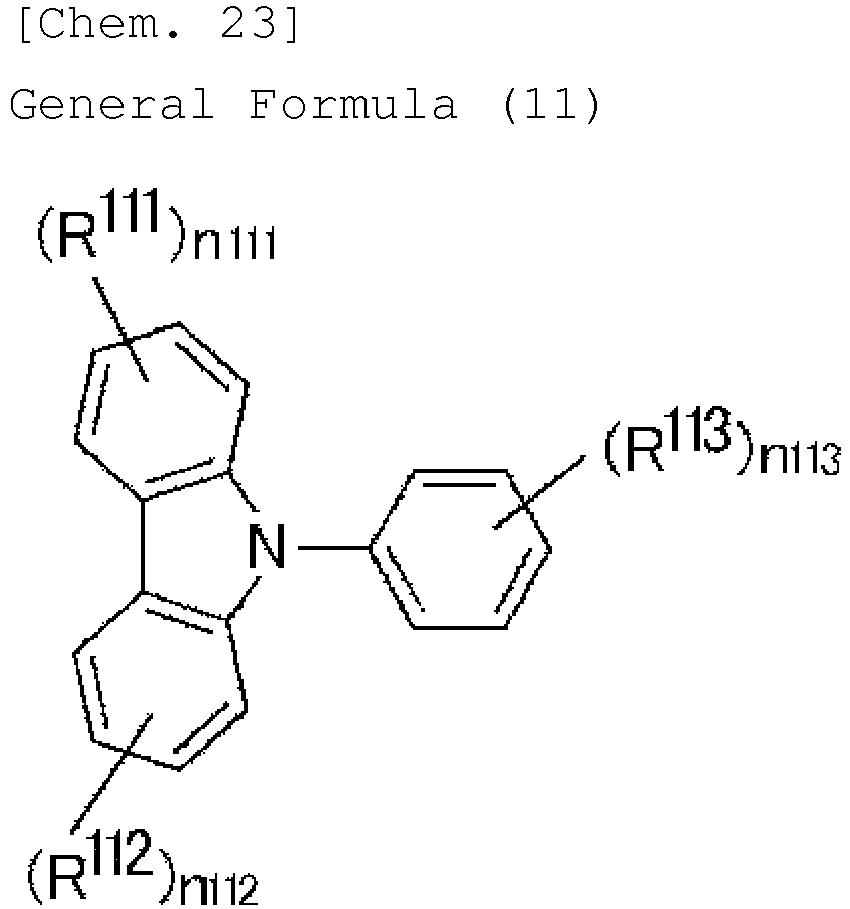
- In the general formula (11), R111, R112 and R113 each independently represent a substituent, n111 and n112 each independently indicate an integer of from 1 to 4, n113 indicates an integer of from 1 to 5. At least one R111, at least one R112, and at least one R113 each are an aryl group. When n111 is an integer of from 2 to 4, n111's R111's may be the same or different; when n112 is an integer of from 2 to 4, n112' s R112's may be the same or different; and when n113 is an integer of from 2 to 5, n113's R113's may be the same or different.
- Preferably, in the general formula (11), n111, n112 and n113 each are from 1 to 3, more preferably 1 or 2.
- In the following, specific examples of the compounds represented by the general formula (10) or the general formula (11) are shown; however, the compounds represented by the general formula (10) or the general formula (11) for use in the invention should not be limitatively interpreted by these specific examples.


- The hole blocking layer has a function of preventing the holes having passed through the light-emitting layer from moving toward the side of cathode. Preferably, the hole blocking layer is formed between the light-emitting layer and the organic layer on the cathode side. The organic material to form the hole blocking layer includes aluminium complex compounds, gallium complex compounds, phenanthroline derivatives, silol derivatives, quinolinol derivative metal complexes, oxadiazole derivatives, oxazole derivatives. Concretely, there are mentioned bis(8-hydroxyquinolinate)(4-phenylphenolate)aluminium, bis(2-methyl-8-hydroxyquinolinate)(4-phenylphenolate)galliu m, 2,9-dimethyl-4,7-diphenyl-1,10-phenanthroline (BCP), etc. One organic material alone or two or more different types of organic materials may be selected for the hole blocking layer either singly or as combined. The hole blocking layer may be formed, for example, according to a vapor deposition method, a sputtering method or a coating method. The thickness of the hole blocking layer may be generally at least 3 nm but is preferably at least 10 nm. The upper limit may be, for example, at most 5 µm.
- The electron injection layer has a function of transporting electrons from the cathode to the side of the light-emitting layer. The electron injection layer is formed generally so as to be in contact with the cathode, and therefore the layer is preferably excellent in the adhesiveness to the cathode surface. The electron transport layer has a function of transporting electrons to the side of the light-emitting layer. The electron transport layer is formed of a material excellent in electron transportability.
- For the electron injection layer and the electron transport layer, used are electron transport materials having a high electron mobility and a large ionization energy. As the electron transport material, various materials that are said to be usable as the electron injection layer or the electron transport layer of organic electroluminescence elements may be used here as suitably selected. The electron transport material may be a polymer material having a recurring unit or may also be a low-molecular compound.
- As the electron transport material, for example, there may be mentioned fluorenone derivatives, anthraquinodimethane derivatives, diphenoquinone derivatives, thiopyran dioxide derivatives, oxazole derivatives, thiazole derivatives, oxadiazole derivatives, triazole derivatives, imidazole derivatives, perylenetetracarboxylic acid derivatives, quinoxaline derivatives, fluorenylidenemethane derivatives, anthraquinodimethane derivatives, anthrone derivatives, etc. Specific examples of preferred electron transport materials include 2,5-bis(1-phenyl)-1,3,4-oxazole, 2,5-bis(1-phenyl)-1,3,4-thiazole, 2,5-bis(1-phenyl)-1,3,4-oxadiazole, 2-(4'-tert-butylphenyl)-5-(4"-biphenyl)-1,3,4-oxadiazole, 2,5-bis(1-naphthyl)-1,3,4-oxadiazole, 1,4-bis[2-(5-phenyloxadiazolyl)]benzene, 1,4-bis[2-(5-phenyloxadiazolyl)-4-tert-butylbenzene], 2-(4'-tert-butylphenyl)-5-(4"-biphenyl)-1,3,4-thiadiazole, 2,5-bis(1-naphthyl)-1,3,4-thiadiazole, 1,4-bis[2-(5-phenylthiadiazolyl)]benzene, 2-(4'-tert-butylphenyl)-5-(4"-biphenyl)-1,3,4-triazole, 2,5-bis(1-naphthyl)-1,3,4-triazole, 1,4-bis[2-(5-phenyltriazolyl)]benzene, lithium 8-hydroxyquinolinate, zinc bis(8-hydroxyquinolinate), copper bis(8-hydroxyquinolinate), manganese bis(8-hydroxyquinolinate), aluminium tris(8-hydroxyquinolinate), aluminium tris(2-methyl-8-hydroxyquinolinate), gallium tris(8-hydroxyquinolinate), beryllium bis(10-hydroxybenzo[h]quinolinate), zinc bis(10-hydroxybenzo[h]quinolinate), chlorogallium bis(2-methyl-8-quinolinate), gallium bis(2-methyl-8-quinolinate)(o-cresolate), aluminium bis(2-methyl-8-quinolinate)(1-naphtholate), gallium bis(2-methyl-8-quinolinate)(2-naphtholate), etc.
- One alone or two or more different types of electron transport materials may be used in one layer either singly or as suitably selected and combined. The electron injection layer and the electron transport layer may be formed, for example, according to a vapor deposition method, a sputtering method or a coating method. The thickness of the electron injection layer and the electron transport layer may be generally at least 3 nm each, preferably at least 10 nm each. The upper limit may be, for example, at most 5 µm each.
- The cathode has a function of injecting electrons toward the organic layer. As the cathode, preferably used is a material having a low work function. For example, a material having a work function of at most 4 eV is preferably used. Concretely, there are mentioned metals (for example, tin, magnesium, indium, calcium, aluminium, silver), and alloys (for example, aluminium-lithium alloy, magnesium-silver alloy, magnesium-indium alloy). In case where emitted light is taken out from the side of the cathode, preferred is use of a material having a high light transmittance. The transmittance is preferably at least 10%, more preferably at least 50%, even more preferably at least 80%. The thickness of the cathode is generally at least 3 nm, but preferably at least 10 nm. The upper limit may be, for example, at most 1 µm, however, when the cathode is not required to have transparency, the thickness thereof may be further larger. The cathode may be formed, for example, according to a vapor deposition method, a sputtering method, or a coating method. Preferably, a protective layer is formed on the cathode for protecting the cathode. The protective layer of the type is preferably a layer formed of a metal that has a high work function and is stable. For example, a metal layer of aluminium, silver, copper, nickel, chromium, gold, platinum or the like may be formed.
- The organic electroluminescence element of the invention is applicable to a variety of uses. For example, using the organic electroluminescence element of the invention, it is possible to produce organic electroluminescence display devices. For the details, referred to is "Organic EL Display" written by Shizuo Tokito, Chihaya Adachi, Yukihide Murata (Ohm Publishing). In particular, the organic electroluminescence element of the invention is applicable to organic electroluminescence lighting that is much in demand. Examples
- The characteristics of the invention are described more concretely with reference to the following Synthesis Examples, Test Examples and Production Examples. In the following Examples, the materials used, the details of the treatment and the treatment process may be suitably modified or changed not overstepping the spirit and the scope of the invention. Accordingly, the scope of the invention should not be limitatively interpreted by the Examples mentioned below.
-
Compound 1 was synthesized according to the following scheme in this Synthesis Example.

- 6.0 g (18.5 mmol, 100 mL, compound a) of 2-bromotriphenylamine was put into a three-neck flask, purged with nitrogen, and 50 mL of tetrahydrofuran (THF) was added thereto and stirred. After the stirring, the solution was cooled down to -78°C and stirred for 20 minutes. After the stirring, 11.2 mL (18.5 mmol) of an n-butyllithium/hexane solution was added thereto via a syringe, and stirred at -78°C for 2 hours. Next, the solution was added toa mixture of 5.0 g (14.8mmol, compound b) of 2,7-dibromo-9-fluorenone and 200 ml of tetrahydrofuran, via a dropping funnel. The mixture was stirred at room temperature for 20 hours. After the stirring, water was added to the solution and stirred for 30 minutes. The mixture was extracted with ethyl acetate added thereto. The organic layer and the aqueous layer were separated, and the organic layer was dried with sodium sulfate added thereto. The mixture was filtered under suction to separate the filtrate. The obtained filtrate was concentrated and directly used in the next reaction.
- 2,7-Dibromo-9-(2-(diphenylamino)phenyl)-9H-fluoren-9-ol (14.8 mmol, compound c) was put into a 300-mL eggplant flask, and 100 ml of acetic acid and 3.0 ml of concentrated hydrochloric acid were added thereto and heated at 130°C. After the reaction, the mixture was filtered under suction to give a solid. The obtained solid was washed with methanol and water, and the resulting solid was dissolved in 1 L of tetrahydrofuran, and filtered through silica gel. The obtained filtrate was concentrated, and the resulting solid was washed with a mixed solvent of acetone and ethyl acetate to give 4.26 g of a powdery white solid. The yield was 51%.
- 2.00 g (3.53 mmol, compound d) of 2',7'-dibromo-10-phenyl-10H-spiro[acridine-9,9'-fluorene] and 0.792 g (8.84 mmol) of copper(I) cyanide were put into a 100-mL three-neck flask and purged with nitrogen. 50 mL of N-methyl-2-pyrrolidinone was added to the mixture. The mixture was stirred at 170°C for 20 hours. Next, the mixture was added to an aqueous sodium hydroxide solution and stirred, and an aqueous sodium hypochlorite solution was added thereto and further stirred for 30 minutes. The mixture was dissolved in toluene, then the aqueous layer and the organic layer were separated from each other, and the organic layer was washed with water. The organic layer was dried with magnesium sulfate. The obtained mixture was filtered under suction to give a filtrate. Further, the obtained filtrate was concentrated and purified through silica gel column chromatography. In the column chromatography, toluene/hexane = 1/2 was used as the developing solvent, and then toluene and toluene/ethyl acetate = 50/1 mixed solvent were further used as the developing solvents. The obtained fraction was concentrated, and the resulting solid was dissolved in chloroform and separated through GPC. The solid obtained through concentration of the fraction was recrystallized from a mixed solvent of acetone and methanol to give 0.81 g of a needle-like yellow solid (compound 1). The yield was 50%. The compound was identified through 1H-NMR, 13C-NMR, TOF-Mass and elementary analysis.
1H-NMR (500 MHz, CDCl3, TMS, δ) : 6.26 (dd, J=7.8Hz, 1.5Hz, 2H), 6.42 (dd, J=8.4Hz, 0.8Hz, 2H), 6.62 (td, J=7.4Hz, 1.1Hz, 2H), 7.01 (td, J=7.8Hz, 1.5Hz, 2H), 7.49 (d, J=7.8Hz, 2H), 7.61 (t, J=7.5Hz, 1H), 7.73-7.76 (m, 6H), 7.94 (d, J=8.3Hz, 2H) 13C-NMR (125 MHz, CDCl3, δ): 157.49, 141.50, 141.12, 140.30, 132.20, 131.32, 130.91, 129.97, 128.87, 128.36, 127.11, 121.62, 121.29, 120.96, 118.72, 115.48, 113.20, 57.25
TOF-Mass [M+] : Anal. Calcd for C33H19N3: 458.16; Found: 458.24 Elementary Analysis: Anal. Calcd for C33H19N3: C 86.63, H 4.19, N 9.18%; Found: C 86.82, H 4.23, N 9.16%. - In the same manner as in Synthesis Example 1, compounds 2 to 282 and 284 to 354 can be produced.
- Compound 283 was synthesized according to the following scheme in this Synthesis Example.


- 1.5 g (3.4 mmol, compound 141) of 10-phenyl-[spiroacridine-9(10H),9'(10'H)anthracen]-10'-one and 3.9 g (34 mmol) of 1,4-diazabicyclo[2.2.2]octane (abbreviation: DABCO), both known compounds, were put into a 100-mL three-neck flask, and purged with nitrogen. 60 mL of dichloromethane was added to the mixture and stirred. After the stirring, 2.3 g (34 mmol) of malononitrile was added thereto, and then 6.5 g (34 mmol) of titanium tetrachloride was added thereto little by little. 2.7 g (34 mmol) of pyridine was added to the mixture little by little, and in a nitrogen stream atmosphere, this was stirred at room temperature for 20 hours. After the stirring, water was added to the mixture and further stirred. After the stirring, the mixture was extracted with chloroform added thereto. After the extraction, the organic layer and the aqueous layer were separated from each other, and the organic layer was washed with saturated saline water. After the washing, the organic layer was dried with magnesium sulfate added thereto. After the drying, the mixture was filtered under suction to separate the filtrate. The obtained filtrate was concentrated, and the resulting solid was purified through silica gel column chromatography. In the column chromatography, the developing solvent used was a mixed solvent of dichloromethane/hexane = 1/1.
- The obtained fraction was concentrated, and ethanol was added to the resulting solid and irradiated with ultrasonic waves. After the irradiation, the solid was collected to be 0.15 g of a pale orange powdery solid (compound 283). The yield was 9.0%.
1H-NMR (500 MHz, CDCl3, TMS, δ): 8.25 (d, J=8.0Hz, 2H), 7.72 (t, J=7.3Hz, 2H), 7.59 (t, J=7.5Hz, 1H), 7.49-7.41 (m, 8H), 6.94 (t, J=7.8Hz, 2H), 6.65 (t, J=7.5Hz, 2H), 6.39-6.34 (m, 4H). MS(MALDI): m/z calcd:483.17 [M+H]+; found: 483.08. - In this Example, the
compound 1 produced in Synthesis Example 1 was used for the test, and an organic electroluminescence element having the configuration shown inFig. 1 was produced. - A film was formed on a quartz substrate by co-deposition of 10 wt
% compound 1 and mCP, and analyzed for the photoluminescence spectrum, the PL quantum yield and the PL transient decay thereof.Fig. 2 shows the photoluminescence spectrum at an excitation wavelength of 339 nm. The co-deposition film gave green emission, and the PL quantum yield thereof was 35% and was high. Next, for investigating the thermally-activated delayed fluorescence characteristic of thecompound 1, the co-deposition film was analyzed for the PL transient decay thereof using a streak camera. The measured results are shown inFig. 3 . The PL transient decay curve well corresponded to the fitting of the two components, and showed a short-life component of 18 ns and a long-life component of 5.2 ms. Specifically, owing to the presence of thecompound 1 therein, the film gave the thermally-activated delayed fluorescence derived from the long-life component in addition to the short-life fluorescence. - On the
glass 1, a film of indium/tin oxide (ITO) 2 was formed in a thickness of approximately from 30 to 100 nm, and a film ofmCP 3 was further formed thereon in a thickness of 60 nm. Next, 6wt% compound 1 and mCP were co-deposited to form a light-emittinglayer 4 in a thickness of 20 nm. Further on this, a film ofBphen 5 was formed in a thickness of 40 nm. Next, a film of magnesium-silver (MgAg) 6 was vacuum-deposited in a thickness of 100 nm, and then aluminium (Al) 7 was deposited thereon in a thickness of 20 nm, thereby producing an organic electroluminescence element having the configuration shown inFig. 1 . Thus formed, the organic EL element gave a green emission well conforming to the corresponding PL spectrum, which therefore confirmed that the emission from the element was derived from thecompound 1. - On glass, a film of indium/tin oxide (ITO) was formed in a thickness of approximately from 30 to 100 nm, and a film of TAPC was formed thereon in a thickness of 40 nm and a film of mCP was further thereon in a thickness of 5 nm. Next, 6
wt% compound 1 and TPSi-F were co-deposited to form a light-emitting layer in a thickness of 20 nm. Further on this, a film of TmPyPB was formed in a thickness of 35 nm. Next, lithium fluoride (LiF) was vacuum-deposited thereon in a thickness of 1 nm, and then aluminium (Al) was deposited thereon in a thickness of 60 nm, thereby producing an organic electroluminescence element.Fig. 4 shows the electroluminescence (EL) spectrum of the element.Fig. 5 shows the current density-voltage characteristic-luminance characteristic of the element, andFig. 6 shows the external quantum efficiency-current density characteristic thereof. It was confirmed that the external quantum efficiency was 10% and was high.
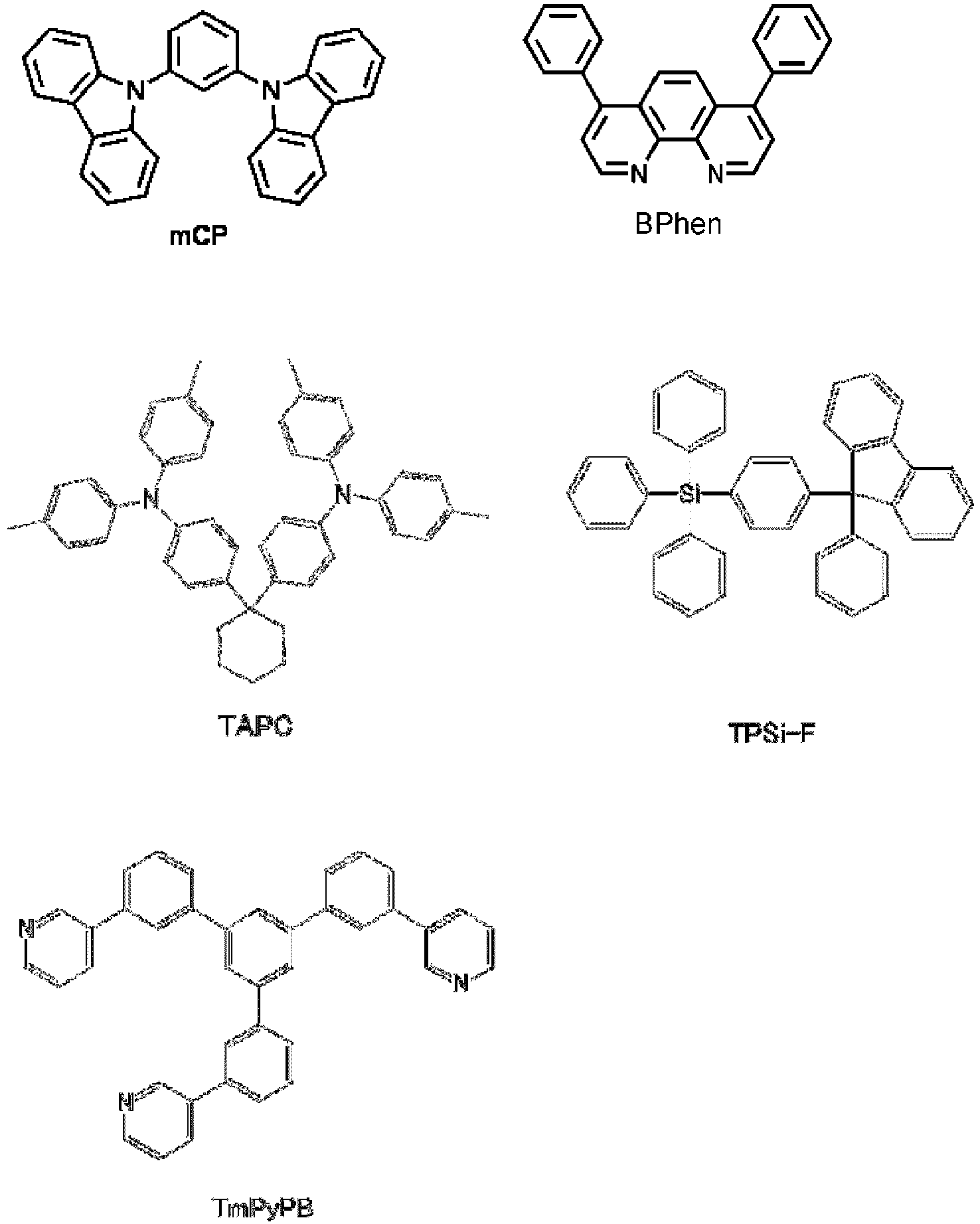
- In the same manner as in Example 1, the usefulness of the compounds 2 to 140 and 142 to 354 can also be confirmed.
- In this Example, the compound 141 was used and tested in the same manner as in Example 1, and an organic electroluminescence element was produced.
- A film was formed on a quartz substrate by co-deposition of 10 wt% compound 141 and DPEPO or UGH2, and analyzed in the same manner as in Example 1 for the photoluminescence spectrum, the PL quantum yield and the PL transient decay thereof.
Fig. 7 shows the photoluminescence spectrum at an excitation wavelength of 339 nm.Fig. 8 shows the PL transient decay curve. Owing to the presence of the compound 141 therein, the film gave the thermally-activated delayed fluorescence derived from the long-life component in addition to the short-life fluorescence. The PL quantum yield was 74 in co-deposition with DPEPO and was 80% in co-deposition with UGH2, and both were high. - On glass, a film of indium/tin oxide (ITO) was formed in a thickness of approximately 100 nm, and a film of NPD was formed thereon in a thickness of 40 nm and a film of mCP was further thereon in a thickness of 10 nm. Next, 9 wt% compound 141 and DPEPO were co-deposited to form a light-emitting layer in a thickness of 40 nm. Further on this, a film of DPEPO was formed in a thickness of 20 nm. Next, magnesium-silver (MgAg = 10/1) was vacuum-deposited thereon in a thickness of 100 nm, and then aluminium (Al) was deposited thereon in a thickness of 10 nm, thereby producing an organic electroluminescence element.
Fig. 9 shows the electroluminescence (EL) spectrum of the element. This well conformed to the corresponding PL spectrum, which therefore confirmed that the emission from the element was derived from the compound 141.Fig. 10 shows the current density-voltage characteristic-luminance characteristic of the element, andFig. 11 shows the external quantum efficiency-current density characteristic thereof. It was confirmed that the external quantum efficiency was 10.7% and was high.

- The organic electroluminescence element of the invention can be produced at a low cost, and can realize a high emission efficiency. In addition, the compound of the invention is useful as a light-emitting material for such organic electroluminescence elements. Consequently, the industrial applicability of the invention is great.
-
- 1
- Glass
- 2
- ITO
- 3
- mCP
- 4
- Light-Emitting Layer
- 5
- Bphen
- 6
- MgAg
- 7
- Al
Claims (24)
- An organic electroluminescence element having an anode, a cathode, and at least one organic layer containing a light-emitting layer between the anode and the cathode, wherein the light-emitting layer contains a compound represented by the following general formula (1):

- The organic electroluminescence element according to Claim 1, which radiates delayed fluorescence.
- The organic electroluminescence element according to Claim 1 or 2, wherein Z in the general formula (1) is a single bond.
- The organic electroluminescence element according to Claim 1 or 2, wherein Z in the general formula (1) is a carbonyl group.
- The organic electroluminescence element according to Claim 1 or 2, wherein Z in the general formula (1) is >C=C (CN)2.
- The organic electroluminescence element according to any one of Claims 1 to 5, wherein R17 in the general formula (1) is an aryl group.
- The organic electroluminescence element according to any one of Claims 1 to 6, wherein at least one of R1, R2, R3, R4, R5, R6, R7 and R8 in the general formula (1) is an aryl group substituted with an electron-donating group.
- The organic electroluminescence element according to any one of Claims 1 to 6, wherein at least one of R1, R2, R3, R4, R5, R6, R7 and R8 in the general formula (1) has a structure represented by the following general formula (2):

- The organic electroluminescence element according to any one of Claims 1 to 6, wherein at least one of R1, R2, R3, R4, R5, R6, R7 and R8 in the general formula (1) has a structure represented by any of the following general formulae (3) to (5) :

- The organic electroluminescence element according to any one of Claims 1 to 6, wherein at least one of R1, R2, R3, R4, R5, R6, R7 and R8 in the general formula (1) has any of the following structures:

- The organic electroluminescence element according to any one of Claims 1 to 10, wherein at least one of R9, R10, R11, R12, R13, R14, R15 and R16 is a cyano group or has a structure represented by any of the following general formulae (6) to (9):
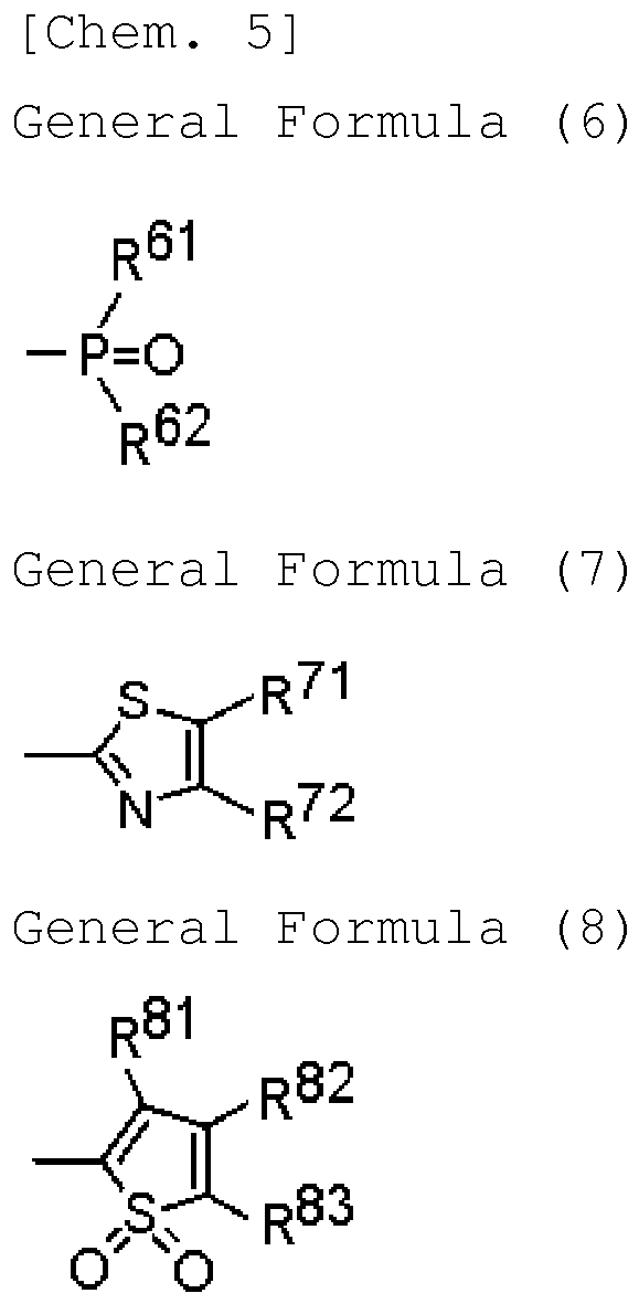

- The organic electroluminescence element according to any one of Claims 1 to 10, wherein at least one of R9, R10, R11, R12, R13, R14, R15 and R16 in the general formula (1) has any of the following structures:

- The organic electroluminescence element according to any one of Claims 1 to 12, wherein the compound represented by the general formula (1) is used as the dopant in the light-emitting layer.
- A compound represented by the following general formula (1') :

- The compound according to Claim 14, wherein Z' in the general formula (1') is a single bond.
- The compound according to Claim 14, wherein Z' in the general formula (1') is a carbonyl group.
- The compound according to Claim 14, wherein Z' in the general formula (1') is >C=C(CN)2.
- The compound according to any one of Claims 14 to 17, wherein R17' in the general formula (1') is an aryl group.
- The compound according to any one of Claims 14 to 17, wherein at least one of R1', R2', R3', R4', R5', R6', R7' and R8' in the general formula (1') is an aryl group substituted with an electron-donating group.
- The compound according to any one of Claims 14 to 17, wherein at least one of R1', R2', R3', R4', R5', R6', R7' and R8' in the general formula (1') has a structure represented by the following general formula (2):

- The compound according to any one of Claims 14 to 17, wherein at least one of R1', R2', R3', R4', R5', R6', R7' and R8' in the general formula (1') has a structure represented by any of the following general formulae (3) to (5):
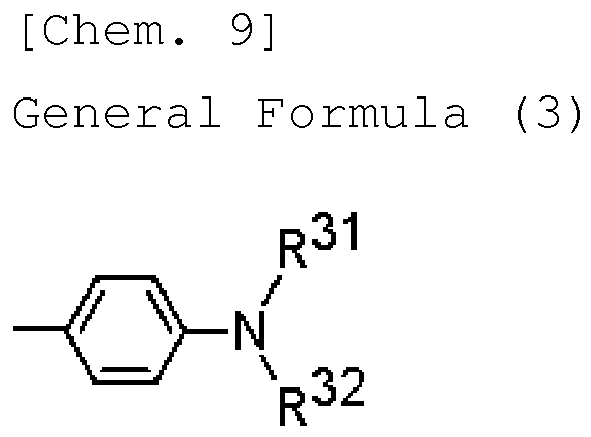

- The compound according to any one of Claims 14 to 17, wherein at least one of R1', R2', R3', R4', R5', R6', R7' and R8' in the general formula (1') has any of the following structures:

- A delayed fluorescence material comprising a compound represented by the following general formula (1):
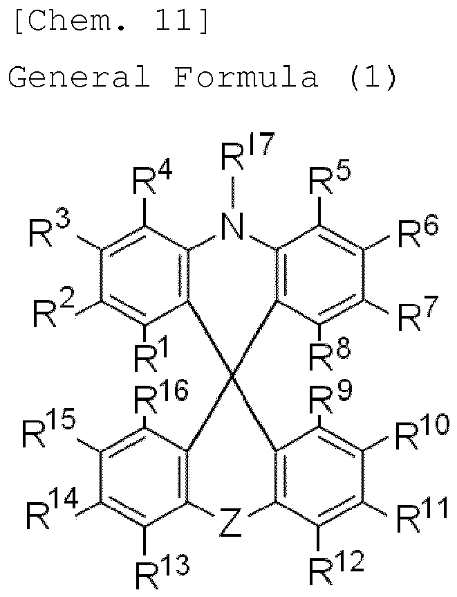
- A delayed fluorescence material comprising a compound represented by the following general formula (1'):


Applications Claiming Priority (4)
| Application Number | Priority Date | Filing Date | Title |
|---|---|---|---|
| JP2011157029 | 2011-07-15 | ||
| JP2012016313 | 2012-01-30 | ||
| JP2012092585 | 2012-04-16 | ||
| PCT/JP2012/067969 WO2013011954A1 (en) | 2011-07-15 | 2012-07-13 | Organic electroluminescence element and compound used therein |
Publications (3)
| Publication Number | Publication Date |
|---|---|
| EP2733762A1 true EP2733762A1 (en) | 2014-05-21 |
| EP2733762A4 EP2733762A4 (en) | 2015-04-15 |
| EP2733762B1 EP2733762B1 (en) | 2018-11-28 |
Family
ID=47558132
Family Applications (1)
| Application Number | Title | Priority Date | Filing Date |
|---|---|---|---|
| EP12815130.5A Active EP2733762B1 (en) | 2011-07-15 | 2012-07-13 | Organic electroluminescence element and compound used therein |
Country Status (7)
| Country | Link |
|---|---|
| US (1) | US9660198B2 (en) |
| EP (1) | EP2733762B1 (en) |
| JP (1) | JP5565742B2 (en) |
| KR (1) | KR102006506B1 (en) |
| CN (1) | CN103650195B (en) |
| TW (1) | TWI585187B (en) |
| WO (1) | WO2013011954A1 (en) |
Cited By (5)
| Publication number | Priority date | Publication date | Assignee | Title |
|---|---|---|---|---|
| WO2016091351A1 (en) * | 2014-12-09 | 2016-06-16 | Merck Patent Gmbh | Electronic device |
| EP3038181A1 (en) | 2014-12-22 | 2016-06-29 | Solvay SA | Organic electronic devices comprising acridine derivatives in an emissive layer free of heavy atom compounds |
| EP2984152B1 (en) * | 2013-04-08 | 2018-04-25 | Merck Patent GmbH | Organic electroluminescent device |
| EP3367456A1 (en) * | 2017-02-28 | 2018-08-29 | Samsung Electronics Co., Ltd. | Organic light-emitting device |
| US10388888B2 (en) | 2014-12-29 | 2019-08-20 | University Court Of The University Of St Andrews | Light emitting electrochemical cells and compounds |
Families Citing this family (91)
| Publication number | Priority date | Publication date | Assignee | Title |
|---|---|---|---|---|
| KR102077994B1 (en) | 2011-09-21 | 2020-02-17 | 메르크 파텐트 게엠베하 | Carbazole derivatives for organic electroluminescence devices |
| WO2013045410A1 (en) | 2011-09-28 | 2013-04-04 | Solvay Sa | Spirobifluorene compounds for light emitting devices |
| KR20210124523A (en) | 2011-11-17 | 2021-10-14 | 메르크 파텐트 게엠베하 | Spirodihydroacridine derivatives and the use thereof as materials for organic electroluminescent devices |
| CN104073240A (en) * | 2013-03-26 | 2014-10-01 | 海洋王照明科技股份有限公司 | Organic electrophosphorescent material and preparation method thereof, and organic electroluminescent device |
| US10600983B2 (en) | 2013-03-29 | 2020-03-24 | Kyulux, Inc. | Organic electroluminescent device comprising delayed fluorescent materials |
| WO2014175627A1 (en) | 2013-04-22 | 2014-10-30 | 주식회사 엘지화학 | Nitrogen-containing heterocyclic compound and organic electronic device comprising same |
| KR102253192B1 (en) * | 2013-06-06 | 2021-05-17 | 메르크 파텐트 게엠베하 | Organic electroluminescent device |
| CN108822137A (en) | 2013-06-26 | 2018-11-16 | 出光兴产株式会社 | Compound, material for organic electroluminescent element, and electronic device |
| JP5669163B1 (en) | 2013-08-14 | 2015-02-12 | 国立大学法人九州大学 | Organic electroluminescence device |
| WO2015029964A1 (en) * | 2013-08-30 | 2015-03-05 | コニカミノルタ株式会社 | Organic electroluminescence element, light-emitting material, light-emitting thin film, display device, and lighting device |
| JP6441896B2 (en) | 2014-03-11 | 2018-12-19 | 株式会社Kyulux | Organic light emitting device, host material, light emitting material and compound |
| US10734587B2 (en) | 2014-03-13 | 2020-08-04 | Merck Patent Gmbh | Formulations of luminescent compounds |
| US20170092875A1 (en) | 2014-03-18 | 2017-03-30 | Merck Patent Gmbh | Organic electroluminescent device |
| CN103985822B (en) * | 2014-05-30 | 2017-05-10 | 广州华睿光电材料有限公司 | Organic mixture, composite containing organic mixture, organic electronic device and application |
| KR101887155B1 (en) * | 2014-08-22 | 2018-08-10 | 샤프 가부시키가이샤 | Organic electroluminescent element, manufacturing method for same, and light emission method |
| JP6534250B2 (en) | 2014-09-03 | 2019-06-26 | 保土谷化学工業株式会社 | Host material for delaying phosphor, organic light emitting device and compound |
| KR102493553B1 (en) | 2014-12-12 | 2023-01-30 | 메르크 파텐트 게엠베하 | Organic compounds with soluble groups |
| EP3240856B1 (en) * | 2014-12-30 | 2018-12-12 | Dow Global Technologies LLC | Fluorene derivatives as light emitting elements for electroluminescent devices |
| CN104892578B (en) * | 2015-05-19 | 2018-01-05 | 苏州大学 | Fluorenes spiral shell triphenylamine derivative and application thereof |
| JP6769712B2 (en) | 2015-07-01 | 2020-10-14 | 国立大学法人九州大学 | Organic electroluminescence device |
| WO2017080326A1 (en) | 2015-11-12 | 2017-05-18 | 广州华睿光电材料有限公司 | Printing composition, electronic device comprising same and preparation method for functional material thin film |
| CN108137634B (en) | 2015-12-04 | 2020-11-20 | 广州华睿光电材料有限公司 | Metal organic complex and application thereof in electronic device |
| JP6808329B2 (en) * | 2016-02-25 | 2021-01-06 | 株式会社ジャパンディスプレイ | Materials for organic electroluminescence display devices and organic electroluminescence display devices |
| CN107056758B (en) * | 2016-04-25 | 2020-06-09 | 中节能万润股份有限公司 | Compound with acridine spiroanthrone as core and application thereof in organic electroluminescent device |
| CN107068911B (en) * | 2016-04-25 | 2019-05-14 | 中节能万润股份有限公司 | A kind of organic electroluminescence device containing anthracene ketone compounds and its application |
| CN107093676B (en) * | 2016-04-25 | 2019-06-14 | 中节能万润股份有限公司 | A kind of organic electroluminescence device containing acridine spiral shell anthracene ketone compounds and its application |
| CN105884830B (en) * | 2016-05-11 | 2018-06-19 | 中节能万润股份有限公司 | A kind of bipolarity OLED phosphorescent light body materials and the luminescent device comprising the material |
| WO2017194435A1 (en) | 2016-05-11 | 2017-11-16 | Merck Patent Gmbh | Compositions for electrochemical cells |
| CN106008264B (en) * | 2016-05-20 | 2017-11-10 | 中节能万润股份有限公司 | A kind of electroluminescent organic material, application and its device |
| CN106467524B (en) * | 2016-07-29 | 2019-04-19 | 江苏三月光电科技有限公司 | A kind of organic aromatic compound and its application on organic electroluminescence device |
| CN106467523B (en) * | 2016-07-29 | 2019-04-09 | 江苏三月光电科技有限公司 | A kind of organic aromatic compound and its application |
| CN106243119B (en) * | 2016-07-29 | 2018-06-29 | 东北林业大学 | A kind of spiral shell and ring material and preparation method thereof |
| EP3512306A4 (en) | 2016-09-06 | 2020-04-08 | Kyulux, Inc. | Organic light-emitting device |
| KR102625862B1 (en) | 2016-10-11 | 2024-01-17 | 삼성디스플레이 주식회사 | Compound and Organic light emitting device comprising same |
| CN106566533A (en) * | 2016-10-26 | 2017-04-19 | 华南理工大学 | Condensed ring oxidized thiophene-based organic luminescent material, and preparation method and application thereof |
| EP3547384B1 (en) | 2016-11-23 | 2022-10-05 | Guangzhou Chinaray Optoelectronic Materials Ltd. | High polymer, mixture containing same, composition, organic electronic component, and monomer for polymerization |
| WO2018095397A1 (en) | 2016-11-23 | 2018-05-31 | 广州华睿光电材料有限公司 | Organic compound containing boron and uses thereof, organic mixture, and organic electronic device |
| CN109790088A (en) | 2016-11-23 | 2019-05-21 | 广州华睿光电材料有限公司 | Fused ring compound, high polymer, mixture, composition and organic electronic device |
| WO2018095382A1 (en) | 2016-11-23 | 2018-05-31 | 广州华睿光电材料有限公司 | Aromatic amine derivative, preparation method therefor, and uses thereof |
| WO2018095379A1 (en) | 2016-11-23 | 2018-05-31 | 广州华睿光电材料有限公司 | Metal organic complex, high polymer, composition, and organic electronic component |
| US11447496B2 (en) | 2016-11-23 | 2022-09-20 | Guangzhou Chinaray Optoelectronic Materials Ltd. | Nitrogen-containing fused heterocyclic ring compound and application thereof |
| CN109790459B (en) | 2016-11-23 | 2022-08-12 | 广州华睿光电材料有限公司 | Organic compounds |
| CN109791993B (en) | 2016-11-23 | 2021-01-15 | 广州华睿光电材料有限公司 | Organic mixture, composition and organic electronic device |
| US11248138B2 (en) | 2016-11-23 | 2022-02-15 | Guangzhou Chinaray Optoelectronic Materials Ltd. | Printing ink formulations, preparation methods and uses thereof |
| KR20180066339A (en) | 2016-12-07 | 2018-06-19 | 삼성디스플레이 주식회사 | Condensed compound and organic light emitting device comprising the same |
| EP3553152B1 (en) | 2016-12-08 | 2021-02-17 | Guangzhou Chinaray Optoelectronic Materials Ltd. | Mixture, composition and organic electronic device |
| WO2018103748A1 (en) | 2016-12-08 | 2018-06-14 | 广州华睿光电材料有限公司 | Pyrene-triazine derivative and applications thereof in organic electronic component |
| KR20180068375A (en) | 2016-12-13 | 2018-06-22 | 삼성디스플레이 주식회사 | Compound and Organic light emitting device comprising same |
| US11161933B2 (en) | 2016-12-13 | 2021-11-02 | Guangzhou Chinaray Optoelectronic Materials Ltd. | Conjugated polymer and use thereof in organic electronic device |
| EP3560917B1 (en) | 2016-12-22 | 2023-12-20 | Guangzhou Chinaray Optoelectronic Materials Ltd. | Polymer containing furan crosslinking group and use thereof |
| WO2018113786A1 (en) | 2016-12-22 | 2018-06-28 | 广州华睿光电材料有限公司 | Cross-linkable polymer based on diels-alder reaction and use thereof in organic electronic device |
| CN108250130B (en) * | 2016-12-28 | 2021-01-22 | 昆山国显光电有限公司 | Organic light-emitting layer host material, organic light-emitting layer and organic light-emitting device |
| US11482679B2 (en) | 2017-05-23 | 2022-10-25 | Kyushu University, National University Corporation | Compound, light-emitting lifetime lengthening agent, use of n-type compound, film and light-emitting device |
| CN107325076B (en) * | 2017-06-29 | 2019-09-27 | 上海天马有机发光显示技术有限公司 | A kind of compound and its luminescent device and display device |
| KR102064646B1 (en) * | 2017-06-30 | 2020-01-09 | 주식회사 엘지화학 | Organic light emitting device |
| CN107325108B (en) * | 2017-07-05 | 2020-05-05 | 中节能万润股份有限公司 | Xanthene spiroazaanthrone organic electroluminescent material, preparation method and application thereof |
| CN110870088A (en) | 2017-07-06 | 2020-03-06 | 九州有机光材股份有限公司 | Organic light emitting element |
| US11476435B2 (en) | 2017-08-24 | 2022-10-18 | Kyushu University, National University Corporation | Film and organic light-emitting device containing perovskite-type compound and organic light-emitting material |
| WO2019114764A1 (en) | 2017-12-14 | 2019-06-20 | 广州华睿光电材料有限公司 | Organometallic complex, and polymer, mixture and composition comprising same, and use thereof in electronic device |
| CN111247159A (en) | 2017-12-14 | 2020-06-05 | 广州华睿光电材料有限公司 | Transition metal complex material and application thereof in electronic device |
| US11674080B2 (en) | 2017-12-14 | 2023-06-13 | Guangzhou Chinaray Optoelectronic Materials Ltd. | Transition metal complex, polymer, mixture, formulation and use thereof |
| CN111315721B (en) | 2017-12-21 | 2023-06-06 | 广州华睿光电材料有限公司 | Organic mixtures and their use in organic electronic devices |
| CN108117539A (en) * | 2017-12-26 | 2018-06-05 | 南京高光半导体材料有限公司 | A kind of organic electroluminescent compounds, organic electroluminescence device and its application |
| WO2019182411A1 (en) * | 2018-03-23 | 2019-09-26 | 주식회사 엘지화학 | Heterocyclic compound and organic light-emitting device comprising same |
| KR20200142554A (en) | 2018-04-11 | 2020-12-22 | 나노코 테크놀로지스 리미티드 | Quantum Dot Architecture for Fluorescent Donor Supported OLED Devices |
| US20210155849A1 (en) | 2018-04-11 | 2021-05-27 | Nanoco Technologies Ltd. | Top-emitting printed display with quantum dots and thermally activated delayed fluorescence molecules |
| KR20190119701A (en) | 2018-04-12 | 2019-10-23 | 삼성디스플레이 주식회사 | Heterocyclic compound and organic light emitting device comprising the same |
| CN109134446B (en) * | 2018-09-30 | 2021-03-05 | 上海天马有机发光显示技术有限公司 | Thermal activation delayed fluorescent material and organic light-emitting display device comprising same |
| WO2020076796A1 (en) | 2018-10-09 | 2020-04-16 | Kyulux, Inc. | Novel composition of matter for use in organic light-emitting diodes |
| CN113227316A (en) | 2018-11-16 | 2021-08-06 | 九州有机光材股份有限公司 | Electroluminescent display device and method of manufacturing the same |
| US20220127286A1 (en) | 2019-03-04 | 2022-04-28 | Merck Patent Gmbh | Ligands for nano-sized materials |
| TW202104238A (en) | 2019-04-11 | 2021-02-01 | 德商麥克專利有限公司 | Materials for organic electroluminescent devices |
| CN114641482A (en) | 2019-11-04 | 2022-06-17 | 默克专利有限公司 | Material for organic electroluminescent device |
| KR20210056497A (en) | 2019-11-08 | 2021-05-20 | 삼성디스플레이 주식회사 | Organic electroluminescence device and polycyclic compound for organic electroluminescence device |
| TW202134252A (en) | 2019-11-12 | 2021-09-16 | 德商麥克專利有限公司 | Materials for organic electroluminescent devices |
| TW202136181A (en) | 2019-12-04 | 2021-10-01 | 德商麥克專利有限公司 | Materials for organic electroluminescent devices |
| US20230119624A1 (en) | 2020-02-04 | 2023-04-20 | Kyulux, Inc. | Composition, film, organic light emitting element, method for providing light emitting composition, and program |
| EP4126884A1 (en) | 2020-03-23 | 2023-02-08 | Merck Patent GmbH | Materials for organic electroluminescent devices |
| EP4155309A4 (en) | 2020-05-22 | 2023-10-25 | Kyulux, Inc. | Compound, light-emitting material, and light-emitting element |
| CN111718322B (en) * | 2020-06-24 | 2021-11-09 | 武汉天马微电子有限公司 | Compound, display panel and display device |
| WO2022025248A1 (en) | 2020-07-31 | 2022-02-03 | 株式会社Kyulux | Compound, light-emitting material, and light-emitting element |
| JP2023541975A (en) | 2020-09-18 | 2023-10-04 | 三星ディスプレイ株式會社 | organic electroluminescent device |
| KR20230142466A (en) | 2021-02-04 | 2023-10-11 | 가부시키가이샤 큐럭스 | Compounds, light-emitting materials, and organic light-emitting devices |
| JP2022178366A (en) | 2021-05-20 | 2022-12-02 | 株式会社Kyulux | Organic light-emitting element |
| KR20240026148A (en) | 2021-06-23 | 2024-02-27 | 가부시키가이샤 큐럭스 | Organic light emitting devices and membranes |
| JP7222159B2 (en) | 2021-06-23 | 2023-02-15 | 株式会社Kyulux | Compounds, luminescent materials and organic light-emitting devices |
| GB202109069D0 (en) | 2021-06-24 | 2021-08-11 | Univ Edinburgh | Compounds and method |
| JPWO2023282224A1 (en) | 2021-07-06 | 2023-01-12 | ||
| CN117917983A (en) | 2021-09-13 | 2024-04-23 | 默克专利有限公司 | Material for organic electroluminescent device |
| WO2023053835A1 (en) | 2021-09-28 | 2023-04-06 | 株式会社Kyulux | Compound, composition, host material, electron barrier material and organic light emitting element |
| WO2024033282A1 (en) | 2022-08-09 | 2024-02-15 | Merck Patent Gmbh | Materials for organic electroluminescent devices |
Citations (2)
| Publication number | Priority date | Publication date | Assignee | Title |
|---|---|---|---|---|
| WO2006033564A1 (en) * | 2004-09-24 | 2006-03-30 | Lg Chem. Ltd. | New compound and organic light emitting device using the same(10) |
| US20100019658A1 (en) * | 2008-07-22 | 2010-01-28 | Industrial Technology Research Institute | Organic compound and organic electroluminescence device employing the same |
Family Cites Families (30)
| Publication number | Priority date | Publication date | Assignee | Title |
|---|---|---|---|---|
| US5030420A (en) | 1982-12-23 | 1991-07-09 | University Of Virginia Alumni Patents Foundation | Apparatus for oxygen determination |
| CA1261717A (en) | 1982-12-23 | 1989-09-26 | John R. Bacon | Method and apparatus for oxygen determination |
| DE59510315D1 (en) | 1994-04-07 | 2002-09-19 | Covion Organic Semiconductors | Spiro compounds and their use as electroluminescent materials |
| US5830138A (en) | 1996-12-16 | 1998-11-03 | Trustees Of The University Of Pennsylvania | Intravascular catheter probe for clinical oxygen, pH and CO2 measurement |
| EP1341403B8 (en) * | 2000-11-24 | 2016-07-06 | Toray Industries, Inc. | Luminescent element material and luminescent element comprising the same |
| JP3835600B2 (en) | 2001-11-14 | 2006-10-18 | 富士電機ホールディングス株式会社 | Oxygen concentration measuring element and manufacturing method thereof |
| US7014925B2 (en) | 2003-04-29 | 2006-03-21 | Canon Kabushiki Kaisha | Heterogeneous spiro compounds in organic light emitting device elements |
| JP2006033564A (en) | 2004-07-20 | 2006-02-02 | Matsushita Electric Ind Co Ltd | Radio communication system |
| JP4012898B2 (en) | 2004-09-07 | 2007-11-21 | 日本電信電話株式会社 | Electric field communication system, electric field communication transceiver |
| JP4431968B2 (en) | 2004-09-07 | 2010-03-17 | ソニー株式会社 | Signal processing apparatus and video display apparatus |
| JP4355942B2 (en) | 2004-09-07 | 2009-11-04 | 日本電気株式会社 | Cellular mobile communication network station setting centralized management modeling system and method |
| JP4339764B2 (en) | 2004-09-07 | 2009-10-07 | パナソニック株式会社 | Facsimile machine |
| JP4513467B2 (en) | 2004-09-07 | 2010-07-28 | 住友電気工業株式会社 | Spread spectrum communication equipment |
| JP2006080637A (en) | 2004-09-07 | 2006-03-23 | Canon Inc | Image recording and reproducing apparatus, sound reproducing method, and program |
| JP2006080642A (en) | 2004-09-07 | 2006-03-23 | Sony Corp | Information processing apparatus and method, program, and recording medium |
| JP4459762B2 (en) | 2004-09-07 | 2010-04-28 | 株式会社日立国際電気 | Integrated broadcast communication system |
| JP2006080644A (en) | 2004-09-07 | 2006-03-23 | Toshiba Tec Corp | Camera |
| TWI279431B (en) | 2004-09-24 | 2007-04-21 | Lg Chemical Ltd | New compound and organic light emitting device using the same |
| CN101400757B (en) | 2006-03-14 | 2013-05-15 | Lg化学株式会社 | Organic light emitting diode having high efficiency and process for fabricating the same |
| JP4882460B2 (en) | 2006-04-03 | 2012-02-22 | パナソニック株式会社 | Humidifier for image monitor |
| US20070254226A1 (en) | 2006-04-26 | 2007-11-01 | Xerox Corporation | Imaging member |
| JP2008096360A (en) | 2006-10-13 | 2008-04-24 | Osaka Univ | Oxygen molecule detection method, oxygen molecule detection probe, and bio-imaging method |
| JP4930943B2 (en) | 2007-05-11 | 2012-05-16 | 国立大学法人群馬大学 | Oxygen concentration measuring reagent and oxygen concentration measuring method |
| JP5255296B2 (en) | 2008-02-27 | 2013-08-07 | 東洋インキScホールディングス株式会社 | Materials and compounds for organic electroluminescence devices |
| US8632893B2 (en) | 2008-07-22 | 2014-01-21 | Industrial Technology Research Institute | Organic compound and organic electroluminescence device employing the same |
| CN101659638B (en) | 2008-08-26 | 2013-10-09 | 财团法人工业技术研究院 | Organic compound and organic electroluminescent device containing same |
| SE533992C2 (en) | 2008-12-23 | 2011-03-22 | Silex Microsystems Ab | Electrical connection in a structure with insulating and conductive bearings |
| TWI503314B (en) * | 2010-02-12 | 2015-10-11 | Ind Tech Res Inst | Organic compound and organic electroluminescence device employing the same |
| CN102229565A (en) * | 2011-05-10 | 2011-11-02 | 南京邮电大学 | Spirofluorene bisbenzoacridine organic semiconductor material, preparation method and use method thereof |
| JP5828518B2 (en) | 2011-07-15 | 2015-12-09 | 国立大学法人九州大学 | Delayed fluorescent material, organic electroluminescence device and compound using the same |
-
2012
- 2012-07-13 EP EP12815130.5A patent/EP2733762B1/en active Active
- 2012-07-13 WO PCT/JP2012/067969 patent/WO2013011954A1/en active Application Filing
- 2012-07-13 CN CN201280035225.XA patent/CN103650195B/en active Active
- 2012-07-13 JP JP2013524706A patent/JP5565742B2/en active Active
- 2012-07-13 KR KR1020147002067A patent/KR102006506B1/en active IP Right Grant
- 2012-07-13 US US14/233,029 patent/US9660198B2/en active Active
- 2012-07-16 TW TW101125565A patent/TWI585187B/en active
Patent Citations (2)
| Publication number | Priority date | Publication date | Assignee | Title |
|---|---|---|---|---|
| WO2006033564A1 (en) * | 2004-09-24 | 2006-03-30 | Lg Chem. Ltd. | New compound and organic light emitting device using the same(10) |
| US20100019658A1 (en) * | 2008-07-22 | 2010-01-28 | Industrial Technology Research Institute | Organic compound and organic electroluminescence device employing the same |
Non-Patent Citations (2)
| Title |
|---|
| See also references of WO2013011954A1 * |
| WEN-YI HUNG ET AL: "An ambipolar host material provides highly efficient saturated red PhOLEDs possessing simple device structures", PHYSICAL CHEMISTRY CHEMICAL PHYSICS, vol. 10, no. 38, 1 January 2008 (2008-01-01), page 5822, XP055142437, ISSN: 1463-9076, DOI: 10.1039/b811356b * |
Cited By (7)
| Publication number | Priority date | Publication date | Assignee | Title |
|---|---|---|---|---|
| EP2984152B1 (en) * | 2013-04-08 | 2018-04-25 | Merck Patent GmbH | Organic electroluminescent device |
| WO2016091351A1 (en) * | 2014-12-09 | 2016-06-16 | Merck Patent Gmbh | Electronic device |
| US10381576B2 (en) | 2014-12-09 | 2019-08-13 | Merck Patent Gmbh | Electronic device having an amine containing layer processed from solution |
| EP3038181A1 (en) | 2014-12-22 | 2016-06-29 | Solvay SA | Organic electronic devices comprising acridine derivatives in an emissive layer free of heavy atom compounds |
| WO2016102412A1 (en) | 2014-12-22 | 2016-06-30 | Solvay Sa | Organic electronic devices comprising acridine derivatives in an emissive layer free of heavy atom compounds |
| US10388888B2 (en) | 2014-12-29 | 2019-08-20 | University Court Of The University Of St Andrews | Light emitting electrochemical cells and compounds |
| EP3367456A1 (en) * | 2017-02-28 | 2018-08-29 | Samsung Electronics Co., Ltd. | Organic light-emitting device |
Also Published As
| Publication number | Publication date |
|---|---|
| TWI585187B (en) | 2017-06-01 |
| EP2733762A4 (en) | 2015-04-15 |
| EP2733762B1 (en) | 2018-11-28 |
| WO2013011954A1 (en) | 2013-01-24 |
| KR20140061365A (en) | 2014-05-21 |
| CN103650195B (en) | 2016-12-07 |
| US20140138670A1 (en) | 2014-05-22 |
| JP5565742B2 (en) | 2014-08-06 |
| KR102006506B1 (en) | 2019-08-01 |
| JPWO2013011954A1 (en) | 2015-02-23 |
| TW201309778A (en) | 2013-03-01 |
| CN103650195A (en) | 2014-03-19 |
| US9660198B2 (en) | 2017-05-23 |
Similar Documents
| Publication | Publication Date | Title |
|---|---|---|
| EP2733762B1 (en) | Organic electroluminescence element and compound used therein | |
| US10454038B2 (en) | Delayed-fluorescence material and organic electroluminescence element using same | |
| JP5828518B2 (en) | Delayed fluorescent material, organic electroluminescence device and compound using the same | |
| EP2415752B1 (en) | Aromatic amine derivative and organic electroluminescent element using same | |
| TWI429650B (en) | Organic electroluminescent elements | |
| TWI458694B (en) | Organic light field components | |
| JP5565743B2 (en) | Organic electroluminescence device and compound used therefor | |
| KR101401639B1 (en) | Novel compound for organic electroluminescent device and organic electroluminescent device comprising the same | |
| JP4002040B2 (en) | Organic electroluminescence device | |
| US20070190356A1 (en) | Material for organic electroluminescent element and organic electroluminescent element employing the same | |
| JPH11111458A (en) | Organic electroluminescent element material and organic electroluminescent element using the same | |
| JP2005082702A (en) | Material for organic electroluminescent device and organic electroluminescent device using the same | |
| JP2000068059A (en) | Organic electroluminescent element material and organic electroluminescent element using the same | |
| JP2000294373A (en) | Material for organic electroluminescence element and organic electroluminescence element using the material | |
| JP2000290645A (en) | Material for organic electroluminescent element and organic electroluminescent element using the same | |
| JP2001207167A (en) | Light-emission material for organic electro-luminescent element and organic electro-luminescent element using the same | |
| JP2000053956A (en) | Luminescent material for organic electroluminescence element and organic electroluminescence element using the same | |
| JP2013098419A (en) | Organic electroluminescent element, and copper complex and light-emitting material for use in the same | |
| TW201402549A (en) | Light emitting element material and light emitting element | |
| JP2000068058A (en) | Luminescent material for organic electroluminescence element and organic electroluminesce element using the same | |
| JP2007306020A (en) | Organic electroluminescence element | |
| JP2007306019A (en) | Organic electroluminescence element |
Legal Events
| Date | Code | Title | Description |
|---|---|---|---|
| PUAI | Public reference made under article 153(3) epc to a published international application that has entered the european phase |
Free format text: ORIGINAL CODE: 0009012 |
|
| 17P | Request for examination filed |
Effective date: 20140206 |
|
| AK | Designated contracting states |
Kind code of ref document: A1 Designated state(s): AL AT BE BG CH CY CZ DE DK EE ES FI FR GB GR HR HU IE IS IT LI LT LU LV MC MK MT NL NO PL PT RO RS SE SI SK SM TR |
|
| DAX | Request for extension of the european patent (deleted) | ||
| RA4 | Supplementary search report drawn up and despatched (corrected) |
Effective date: 20150313 |
|
| RIC1 | Information provided on ipc code assigned before grant |
Ipc: C07D 219/02 20060101ALI20150309BHEP Ipc: H01L 51/50 20060101AFI20150309BHEP Ipc: C09K 11/06 20060101ALI20150309BHEP |
|
| RAP1 | Party data changed (applicant data changed or rights of an application transferred) |
Owner name: KYULUX, INC. |
|
| STAA | Information on the status of an ep patent application or granted ep patent |
Free format text: STATUS: EXAMINATION IS IN PROGRESS |
|
| 17Q | First examination report despatched |
Effective date: 20171102 |
|
| REG | Reference to a national code |
Ref country code: DE Ref legal event code: R079 Ref document number: 602012054153 Country of ref document: DE Free format text: PREVIOUS MAIN CLASS: H01L0051500000 Ipc: H01L0051540000 |
|
| GRAP | Despatch of communication of intention to grant a patent |
Free format text: ORIGINAL CODE: EPIDOSNIGR1 |
|
| STAA | Information on the status of an ep patent application or granted ep patent |
Free format text: STATUS: GRANT OF PATENT IS INTENDED |
|
| RIC1 | Information provided on ipc code assigned before grant |
Ipc: C07D 219/02 20060101ALI20180209BHEP Ipc: H01L 51/54 20060101AFI20180209BHEP Ipc: C09K 11/06 20060101ALI20180209BHEP |
|
| INTG | Intention to grant announced |
Effective date: 20180305 |
|
| GRAJ | Information related to disapproval of communication of intention to grant by the applicant or resumption of examination proceedings by the epo deleted |
Free format text: ORIGINAL CODE: EPIDOSDIGR1 |
|
| STAA | Information on the status of an ep patent application or granted ep patent |
Free format text: STATUS: EXAMINATION IS IN PROGRESS |
|
| GRAP | Despatch of communication of intention to grant a patent |
Free format text: ORIGINAL CODE: EPIDOSNIGR1 |
|
| STAA | Information on the status of an ep patent application or granted ep patent |
Free format text: STATUS: GRANT OF PATENT IS INTENDED |
|
| INTC | Intention to grant announced (deleted) | ||
| INTG | Intention to grant announced |
Effective date: 20180827 |
|
| GRAS | Grant fee paid |
Free format text: ORIGINAL CODE: EPIDOSNIGR3 |
|
| GRAA | (expected) grant |
Free format text: ORIGINAL CODE: 0009210 |
|
| STAA | Information on the status of an ep patent application or granted ep patent |
Free format text: STATUS: THE PATENT HAS BEEN GRANTED |
|
| AK | Designated contracting states |
Kind code of ref document: B1 Designated state(s): AL AT BE BG CH CY CZ DE DK EE ES FI FR GB GR HR HU IE IS IT LI LT LU LV MC MK MT NL NO PL PT RO RS SE SI SK SM TR |
|
| REG | Reference to a national code |
Ref country code: GB Ref legal event code: FG4D |
|
| REG | Reference to a national code |
Ref country code: CH Ref legal event code: EP |
|
| REG | Reference to a national code |
Ref country code: AT Ref legal event code: REF Ref document number: 1071262 Country of ref document: AT Kind code of ref document: T Effective date: 20181215 |
|
| REG | Reference to a national code |
Ref country code: DE Ref legal event code: R096 Ref document number: 602012054153 Country of ref document: DE |
|
| REG | Reference to a national code |
Ref country code: IE Ref legal event code: FG4D |
|
| REG | Reference to a national code |
Ref country code: NL Ref legal event code: MP Effective date: 20181128 |
|
| REG | Reference to a national code |
Ref country code: LT Ref legal event code: MG4D |
|
| REG | Reference to a national code |
Ref country code: AT Ref legal event code: MK05 Ref document number: 1071262 Country of ref document: AT Kind code of ref document: T Effective date: 20181128 |
|
| PG25 | Lapsed in a contracting state [announced via postgrant information from national office to epo] |
Ref country code: ES Free format text: LAPSE BECAUSE OF FAILURE TO SUBMIT A TRANSLATION OF THE DESCRIPTION OR TO PAY THE FEE WITHIN THE PRESCRIBED TIME-LIMIT Effective date: 20181128 Ref country code: LV Free format text: LAPSE BECAUSE OF FAILURE TO SUBMIT A TRANSLATION OF THE DESCRIPTION OR TO PAY THE FEE WITHIN THE PRESCRIBED TIME-LIMIT Effective date: 20181128 Ref country code: HR Free format text: LAPSE BECAUSE OF FAILURE TO SUBMIT A TRANSLATION OF THE DESCRIPTION OR TO PAY THE FEE WITHIN THE PRESCRIBED TIME-LIMIT Effective date: 20181128 Ref country code: LT Free format text: LAPSE BECAUSE OF FAILURE TO SUBMIT A TRANSLATION OF THE DESCRIPTION OR TO PAY THE FEE WITHIN THE PRESCRIBED TIME-LIMIT Effective date: 20181128 Ref country code: BG Free format text: LAPSE BECAUSE OF FAILURE TO SUBMIT A TRANSLATION OF THE DESCRIPTION OR TO PAY THE FEE WITHIN THE PRESCRIBED TIME-LIMIT Effective date: 20190228 Ref country code: FI Free format text: LAPSE BECAUSE OF FAILURE TO SUBMIT A TRANSLATION OF THE DESCRIPTION OR TO PAY THE FEE WITHIN THE PRESCRIBED TIME-LIMIT Effective date: 20181128 Ref country code: IS Free format text: LAPSE BECAUSE OF FAILURE TO SUBMIT A TRANSLATION OF THE DESCRIPTION OR TO PAY THE FEE WITHIN THE PRESCRIBED TIME-LIMIT Effective date: 20190328 Ref country code: NO Free format text: LAPSE BECAUSE OF FAILURE TO SUBMIT A TRANSLATION OF THE DESCRIPTION OR TO PAY THE FEE WITHIN THE PRESCRIBED TIME-LIMIT Effective date: 20190228 Ref country code: AT Free format text: LAPSE BECAUSE OF FAILURE TO SUBMIT A TRANSLATION OF THE DESCRIPTION OR TO PAY THE FEE WITHIN THE PRESCRIBED TIME-LIMIT Effective date: 20181128 |
|
| PG25 | Lapsed in a contracting state [announced via postgrant information from national office to epo] |
Ref country code: SE Free format text: LAPSE BECAUSE OF FAILURE TO SUBMIT A TRANSLATION OF THE DESCRIPTION OR TO PAY THE FEE WITHIN THE PRESCRIBED TIME-LIMIT Effective date: 20181128 Ref country code: AL Free format text: LAPSE BECAUSE OF FAILURE TO SUBMIT A TRANSLATION OF THE DESCRIPTION OR TO PAY THE FEE WITHIN THE PRESCRIBED TIME-LIMIT Effective date: 20181128 Ref country code: RS Free format text: LAPSE BECAUSE OF FAILURE TO SUBMIT A TRANSLATION OF THE DESCRIPTION OR TO PAY THE FEE WITHIN THE PRESCRIBED TIME-LIMIT Effective date: 20181128 Ref country code: GR Free format text: LAPSE BECAUSE OF FAILURE TO SUBMIT A TRANSLATION OF THE DESCRIPTION OR TO PAY THE FEE WITHIN THE PRESCRIBED TIME-LIMIT Effective date: 20190301 Ref country code: PT Free format text: LAPSE BECAUSE OF FAILURE TO SUBMIT A TRANSLATION OF THE DESCRIPTION OR TO PAY THE FEE WITHIN THE PRESCRIBED TIME-LIMIT Effective date: 20190328 |
|
| PG25 | Lapsed in a contracting state [announced via postgrant information from national office to epo] |
Ref country code: NL Free format text: LAPSE BECAUSE OF FAILURE TO SUBMIT A TRANSLATION OF THE DESCRIPTION OR TO PAY THE FEE WITHIN THE PRESCRIBED TIME-LIMIT Effective date: 20181128 |
|
| PG25 | Lapsed in a contracting state [announced via postgrant information from national office to epo] |
Ref country code: IT Free format text: LAPSE BECAUSE OF FAILURE TO SUBMIT A TRANSLATION OF THE DESCRIPTION OR TO PAY THE FEE WITHIN THE PRESCRIBED TIME-LIMIT Effective date: 20181128 Ref country code: DK Free format text: LAPSE BECAUSE OF FAILURE TO SUBMIT A TRANSLATION OF THE DESCRIPTION OR TO PAY THE FEE WITHIN THE PRESCRIBED TIME-LIMIT Effective date: 20181128 Ref country code: PL Free format text: LAPSE BECAUSE OF FAILURE TO SUBMIT A TRANSLATION OF THE DESCRIPTION OR TO PAY THE FEE WITHIN THE PRESCRIBED TIME-LIMIT Effective date: 20181128 Ref country code: CZ Free format text: LAPSE BECAUSE OF FAILURE TO SUBMIT A TRANSLATION OF THE DESCRIPTION OR TO PAY THE FEE WITHIN THE PRESCRIBED TIME-LIMIT Effective date: 20181128 |
|
| REG | Reference to a national code |
Ref country code: DE Ref legal event code: R097 Ref document number: 602012054153 Country of ref document: DE |
|
| PG25 | Lapsed in a contracting state [announced via postgrant information from national office to epo] |
Ref country code: SK Free format text: LAPSE BECAUSE OF FAILURE TO SUBMIT A TRANSLATION OF THE DESCRIPTION OR TO PAY THE FEE WITHIN THE PRESCRIBED TIME-LIMIT Effective date: 20181128 Ref country code: RO Free format text: LAPSE BECAUSE OF FAILURE TO SUBMIT A TRANSLATION OF THE DESCRIPTION OR TO PAY THE FEE WITHIN THE PRESCRIBED TIME-LIMIT Effective date: 20181128 Ref country code: EE Free format text: LAPSE BECAUSE OF FAILURE TO SUBMIT A TRANSLATION OF THE DESCRIPTION OR TO PAY THE FEE WITHIN THE PRESCRIBED TIME-LIMIT Effective date: 20181128 Ref country code: SM Free format text: LAPSE BECAUSE OF FAILURE TO SUBMIT A TRANSLATION OF THE DESCRIPTION OR TO PAY THE FEE WITHIN THE PRESCRIBED TIME-LIMIT Effective date: 20181128 |
|
| PLBE | No opposition filed within time limit |
Free format text: ORIGINAL CODE: 0009261 |
|
| STAA | Information on the status of an ep patent application or granted ep patent |
Free format text: STATUS: NO OPPOSITION FILED WITHIN TIME LIMIT |
|
| PG25 | Lapsed in a contracting state [announced via postgrant information from national office to epo] |
Ref country code: SI Free format text: LAPSE BECAUSE OF FAILURE TO SUBMIT A TRANSLATION OF THE DESCRIPTION OR TO PAY THE FEE WITHIN THE PRESCRIBED TIME-LIMIT Effective date: 20181128 |
|
| 26N | No opposition filed |
Effective date: 20190829 |
|
| PG25 | Lapsed in a contracting state [announced via postgrant information from national office to epo] |
Ref country code: MC Free format text: LAPSE BECAUSE OF FAILURE TO SUBMIT A TRANSLATION OF THE DESCRIPTION OR TO PAY THE FEE WITHIN THE PRESCRIBED TIME-LIMIT Effective date: 20181128 |
|
| REG | Reference to a national code |
Ref country code: CH Ref legal event code: PL |
|
| PG25 | Lapsed in a contracting state [announced via postgrant information from national office to epo] |
Ref country code: TR Free format text: LAPSE BECAUSE OF FAILURE TO SUBMIT A TRANSLATION OF THE DESCRIPTION OR TO PAY THE FEE WITHIN THE PRESCRIBED TIME-LIMIT Effective date: 20181128 |
|
| REG | Reference to a national code |
Ref country code: BE Ref legal event code: MM Effective date: 20190731 |
|
| PG25 | Lapsed in a contracting state [announced via postgrant information from national office to epo] |
Ref country code: BE Free format text: LAPSE BECAUSE OF NON-PAYMENT OF DUE FEES Effective date: 20190731 Ref country code: CH Free format text: LAPSE BECAUSE OF NON-PAYMENT OF DUE FEES Effective date: 20190731 Ref country code: LI Free format text: LAPSE BECAUSE OF NON-PAYMENT OF DUE FEES Effective date: 20190731 Ref country code: LU Free format text: LAPSE BECAUSE OF NON-PAYMENT OF DUE FEES Effective date: 20190713 |
|
| PG25 | Lapsed in a contracting state [announced via postgrant information from national office to epo] |
Ref country code: IE Free format text: LAPSE BECAUSE OF NON-PAYMENT OF DUE FEES Effective date: 20190713 |
|
| PG25 | Lapsed in a contracting state [announced via postgrant information from national office to epo] |
Ref country code: CY Free format text: LAPSE BECAUSE OF FAILURE TO SUBMIT A TRANSLATION OF THE DESCRIPTION OR TO PAY THE FEE WITHIN THE PRESCRIBED TIME-LIMIT Effective date: 20181128 |
|
| PG25 | Lapsed in a contracting state [announced via postgrant information from national office to epo] |
Ref country code: MT Free format text: LAPSE BECAUSE OF FAILURE TO SUBMIT A TRANSLATION OF THE DESCRIPTION OR TO PAY THE FEE WITHIN THE PRESCRIBED TIME-LIMIT Effective date: 20181128 Ref country code: HU Free format text: LAPSE BECAUSE OF FAILURE TO SUBMIT A TRANSLATION OF THE DESCRIPTION OR TO PAY THE FEE WITHIN THE PRESCRIBED TIME-LIMIT; INVALID AB INITIO Effective date: 20120713 |
|
| PG25 | Lapsed in a contracting state [announced via postgrant information from national office to epo] |
Ref country code: MK Free format text: LAPSE BECAUSE OF FAILURE TO SUBMIT A TRANSLATION OF THE DESCRIPTION OR TO PAY THE FEE WITHIN THE PRESCRIBED TIME-LIMIT Effective date: 20181128 |
|
| REG | Reference to a national code |
Ref country code: DE Ref legal event code: R079 Ref document number: 602012054153 Country of ref document: DE Free format text: PREVIOUS MAIN CLASS: H01L0051540000 Ipc: H10K0085000000 |
|
| P01 | Opt-out of the competence of the unified patent court (upc) registered |
Effective date: 20230509 |
|
| PGFP | Annual fee paid to national office [announced via postgrant information from national office to epo] |
Ref country code: FR Payment date: 20230620 Year of fee payment: 12 |
|
| PGFP | Annual fee paid to national office [announced via postgrant information from national office to epo] |
Ref country code: GB Payment date: 20230601 Year of fee payment: 12 |
|
| PGFP | Annual fee paid to national office [announced via postgrant information from national office to epo] |
Ref country code: DE Payment date: 20230531 Year of fee payment: 12 |