EP2733232A1 - Dispositif de protection de surfaces extérieures par traitement intérieur à l'alite de composants creux - Google Patents
Dispositif de protection de surfaces extérieures par traitement intérieur à l'alite de composants creux Download PDFInfo
- Publication number
- EP2733232A1 EP2733232A1 EP12193051.5A EP12193051A EP2733232A1 EP 2733232 A1 EP2733232 A1 EP 2733232A1 EP 12193051 A EP12193051 A EP 12193051A EP 2733232 A1 EP2733232 A1 EP 2733232A1
- Authority
- EP
- European Patent Office
- Prior art keywords
- component
- container
- blade
- powder
- aluminizing
- Prior art date
- Legal status (The legal status is an assumption and is not a legal conclusion. Google has not performed a legal analysis and makes no representation as to the accuracy of the status listed.)
- Withdrawn
Links
Images

Classifications
-
- C—CHEMISTRY; METALLURGY
- C23—COATING METALLIC MATERIAL; COATING MATERIAL WITH METALLIC MATERIAL; CHEMICAL SURFACE TREATMENT; DIFFUSION TREATMENT OF METALLIC MATERIAL; COATING BY VACUUM EVAPORATION, BY SPUTTERING, BY ION IMPLANTATION OR BY CHEMICAL VAPOUR DEPOSITION, IN GENERAL; INHIBITING CORROSION OF METALLIC MATERIAL OR INCRUSTATION IN GENERAL
- C23C—COATING METALLIC MATERIAL; COATING MATERIAL WITH METALLIC MATERIAL; SURFACE TREATMENT OF METALLIC MATERIAL BY DIFFUSION INTO THE SURFACE, BY CHEMICAL CONVERSION OR SUBSTITUTION; COATING BY VACUUM EVAPORATION, BY SPUTTERING, BY ION IMPLANTATION OR BY CHEMICAL VAPOUR DEPOSITION, IN GENERAL
- C23C8/00—Solid state diffusion of only non-metal elements into metallic material surfaces; Chemical surface treatment of metallic material by reaction of the surface with a reactive gas, leaving reaction products of surface material in the coating, e.g. conversion coatings, passivation of metals
- C23C8/04—Treatment of selected surface areas, e.g. using masks
-
- C—CHEMISTRY; METALLURGY
- C23—COATING METALLIC MATERIAL; COATING MATERIAL WITH METALLIC MATERIAL; CHEMICAL SURFACE TREATMENT; DIFFUSION TREATMENT OF METALLIC MATERIAL; COATING BY VACUUM EVAPORATION, BY SPUTTERING, BY ION IMPLANTATION OR BY CHEMICAL VAPOUR DEPOSITION, IN GENERAL; INHIBITING CORROSION OF METALLIC MATERIAL OR INCRUSTATION IN GENERAL
- C23C—COATING METALLIC MATERIAL; COATING MATERIAL WITH METALLIC MATERIAL; SURFACE TREATMENT OF METALLIC MATERIAL BY DIFFUSION INTO THE SURFACE, BY CHEMICAL CONVERSION OR SUBSTITUTION; COATING BY VACUUM EVAPORATION, BY SPUTTERING, BY ION IMPLANTATION OR BY CHEMICAL VAPOUR DEPOSITION, IN GENERAL
- C23C10/00—Solid state diffusion of only metal elements or silicon into metallic material surfaces
- C23C10/04—Diffusion into selected surface areas, e.g. using masks
-
- C—CHEMISTRY; METALLURGY
- C23—COATING METALLIC MATERIAL; COATING MATERIAL WITH METALLIC MATERIAL; CHEMICAL SURFACE TREATMENT; DIFFUSION TREATMENT OF METALLIC MATERIAL; COATING BY VACUUM EVAPORATION, BY SPUTTERING, BY ION IMPLANTATION OR BY CHEMICAL VAPOUR DEPOSITION, IN GENERAL; INHIBITING CORROSION OF METALLIC MATERIAL OR INCRUSTATION IN GENERAL
- C23C—COATING METALLIC MATERIAL; COATING MATERIAL WITH METALLIC MATERIAL; SURFACE TREATMENT OF METALLIC MATERIAL BY DIFFUSION INTO THE SURFACE, BY CHEMICAL CONVERSION OR SUBSTITUTION; COATING BY VACUUM EVAPORATION, BY SPUTTERING, BY ION IMPLANTATION OR BY CHEMICAL VAPOUR DEPOSITION, IN GENERAL
- C23C10/00—Solid state diffusion of only metal elements or silicon into metallic material surfaces
- C23C10/06—Solid state diffusion of only metal elements or silicon into metallic material surfaces using gases
- C23C10/08—Solid state diffusion of only metal elements or silicon into metallic material surfaces using gases only one element being diffused
Definitions
- the invention relates to a protective device outer surfaces of a hollow component, which should not be coated during mecanical obstructive obstructive obstructive obstructive obstructive obstructive obstructive obstructive obstructive obstructive obstructive obstructive obstructive obstructive obstructive obstructive obstructive osene.
- the object is achieved by an apparatus of claim 1 and a method according to claim 5.
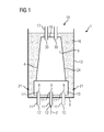
- FIG. 1 1 shows a hollow component 4, in particular a turbine blade 120, 130 as an exemplary component 4 in the interior preferably be alitiert.
- a coating material 12 is introduced into the cavity of the component 4, 120, 130 in the blade root 10 of the component 4, 120, 130.
- aluminum-containing gas 12 is used or generated.
- other materials can be applied and, if appropriate, used or introduced corresponding gases.
- the component 4, 120, 130 is surrounded by a ceramic powder 16.
- the powder 16 may be alumina, boron nitride or any other oxide or non-oxide ceramic material or any mixtures thereof.
- the component 4 or the turbine blade 120, 130 have at their end 10 or in the foot region 10 one or more openings 9 in the cavity.
- the device 1 has a container 13 which is open upwards on one side 19 and which has a plurality of corresponding tubes 11 at the bottom 8, the component 4 preferably being able to be placed on recesses 11 'which are formed at the end of the tubes 11.
- the component 4 is correspondingly with powder 16 in the container 13th surround.
- the container 13 is made higher than the length of the turbine blade 120, 130 or the component. 4
- the bottom 8 of the container 13 can be made modular, which is adapted to different types of the component 4 or turbine blade 120, 130.
- the floor 8 may be releasably secured at locations 21, 21 'and another floor (not shown) with other recesses for other types of components is attached thereto.
- the turbine blade 120, 130 introduced in the simplest manner and placed on recesses 11 '. There are appropriate gas outlets 17 at the top or the opposite end 18 of the bottom 10 is used and then only the cavity between the component 4, 120, 130 and the container 13 with the powder 16 must be filled. This is a simple and very cost effective approach.
- the recesses 11 ' are specially adapted to the openings 9 of the component 4, 120, 130 and are formed at the end of the tubes 11, which pass through the bottom 8.
- the gas 12 flows from the outside into or into the tubes 11 through the bottom 8 and out of outlet openings of the tubes 11 into the component 4, 120, 130, through the component 4, 120, 130 and back out through the gas outlets 17.
- the powder 16 can be used again and again.
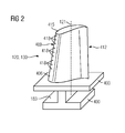
- FIG. 2 shows a perspective view of a blade 120 or guide vane 130 of a turbomachine, which extends along a longitudinal axis 121.
- the turbomachine may be a gas turbine of an aircraft or a power plant for power generation, a steam turbine or a compressor.
- the blade 120, 130 has along the longitudinal axis 121 consecutively a fastening region 400, a blade platform 403 adjacent thereto and an airfoil 406 and a blade tip 415.
- the blade 130 may have at its blade tip 415 another platform (not shown).
- a blade root 183 is formed, which serves for attachment of the blades 120, 130 to a shaft or a disc (not shown).
- the blade root 183 is designed, for example, as a hammer head. Other designs as Christmas tree or Schwalbenschwanzfuß are possible.
- the blade 120, 130 has a leading edge 409 and a trailing edge 412 for a medium flowing past the airfoil 406.
- Such superalloys are for example from EP 1 204 776 B1 .
- EP 1 306 454 .
- the blade 120, 130 can be made by a casting process, also by directional solidification, by a forging process, by a milling process or combinations thereof.
- Workpieces with a monocrystalline structure or structures are used as components for machines which are exposed to high mechanical, thermal and / or chemical stresses during operation.
- Such monocrystalline workpieces takes place e.g. by directed solidification from the melt.
- These are casting processes in which the liquid metallic alloy is transformed into a monocrystalline structure, i. to the single-crystal workpiece, or directionally solidified.
- dendritic crystals are aligned along the heat flow and form either a columnar grain structure (columnar, i.e., grains that run the full length of the workpiece and here, in common usage, are referred to as directionally solidified) or a monocrystalline structure, i. the whole workpiece consists of a single crystal.
- a columnar grain structure columnar, i.e., grains that run the full length of the workpiece and here, in common usage, are referred to as directionally solidified
- a monocrystalline structure i. the whole workpiece consists of a single crystal.
- directionally solidified microstructures which means both single crystals that have no grain boundaries or at most small angle grain boundaries, and stem crystal structures that have probably longitudinal grain boundaries but no transverse grain boundaries. These second-mentioned crystalline structures are also known as directionally solidified structures.
- the blades 120, 130 may have coatings against corrosion or oxidation, e.g. M is at least one element of the group iron (Fe), cobalt (Co), nickel (Ni), X is an active element and stands for yttrium (Y) and / or silicon and / or at least one element of the rare ones Earth, or hafnium (Hf)).
- M is at least one element of the group iron (Fe), cobalt (Co), nickel (Ni)
- X is an active element and stands for yttrium (Y) and / or silicon and / or at least one element of the rare ones Earth, or hafnium (Hf)).
- Such alloys are known from the EP 0 486 489 B1 .
- EP 0 412 397 B1 or EP 1 306 454 A1 are known from the EP 0 486 489 B1 .
- the density is preferably 95% of the theoretical density.
- the layer composition comprises Co-30Ni-28Cr-8Al-0.6Y-0.7Si or Co-28Ni-24Cr-10Al-0.6Y.
- nickel-based protective layers such as Ni-10Cr-12Al-0.6Y-3Re or Ni-12Co-21Cr-11Al-0.4Y-2Re or Ni-25Co-17Cr-10Al-0.4Y-1 are also preferably used , 5RE.
- thermal barrier coating which is preferably the outermost layer, and consists for example of ZrO 2 , Y 2 O 3 -ZrO 2 , ie it is not, partially or completely stabilized by yttria and / or calcium oxide and / or magnesium oxide.
- the thermal barrier coating covers the entire MCrAlX layer.
- suitable coating methods e.g. Electron beam evaporation (EB-PVD) produces stalk-shaped grains in the thermal barrier coating.
- the thermal barrier coating may have porous, micro- or macro-cracked grains for better thermal shock resistance.
- the thermal barrier coating is therefore preferably more porous than the MCrAlX layer.
- Refurbishment means that components 120, 130 may have to be freed of protective layers after use (eg by sandblasting). This is followed by removal of the corrosion and / or oxidation layers or products. Optionally, even cracks in the component 120, 130 are repaired. Thereafter, a recoating occurs of the component 120, 130 and a renewed use of the component 120, 130.
- the blade 120, 130 may be hollow or solid. If the blade 120, 130 is to be cooled, it is hollow and may still film cooling holes 418 (indicated by dashed lines) on.
Priority Applications (1)
| Application Number | Priority Date | Filing Date | Title |
|---|---|---|---|
| EP12193051.5A EP2733232A1 (fr) | 2012-11-16 | 2012-11-16 | Dispositif de protection de surfaces extérieures par traitement intérieur à l'alite de composants creux |
Applications Claiming Priority (1)
| Application Number | Priority Date | Filing Date | Title |
|---|---|---|---|
| EP12193051.5A EP2733232A1 (fr) | 2012-11-16 | 2012-11-16 | Dispositif de protection de surfaces extérieures par traitement intérieur à l'alite de composants creux |
Publications (1)
| Publication Number | Publication Date |
|---|---|
| EP2733232A1 true EP2733232A1 (fr) | 2014-05-21 |
Family
ID=47191621
Family Applications (1)
| Application Number | Title | Priority Date | Filing Date |
|---|---|---|---|
| EP12193051.5A Withdrawn EP2733232A1 (fr) | 2012-11-16 | 2012-11-16 | Dispositif de protection de surfaces extérieures par traitement intérieur à l'alite de composants creux |
Country Status (1)
| Country | Link |
|---|---|
| EP (1) | EP2733232A1 (fr) |
Cited By (1)
| Publication number | Priority date | Publication date | Assignee | Title |
|---|---|---|---|---|
| CN106637068A (zh) * | 2016-12-20 | 2017-05-10 | 四川成发航空科技股份有限公司 | 一种航空发动机导向叶片榫头防渗装置 |
Citations (14)
| Publication number | Priority date | Publication date | Assignee | Title |
|---|---|---|---|---|
| EP0486489B1 (fr) | 1989-08-10 | 1994-11-02 | Siemens Aktiengesellschaft | Revetement anticorrosion resistant aux temperatures elevees, notamment pour elements de turbines a gaz |
| EP0412397B1 (fr) | 1989-08-10 | 1998-03-25 | Siemens Aktiengesellschaft | Revêtement protecteur contenant du rhénium possédant une résistance plus grande à la corrosion et l'oxydation |
| EP0892090A1 (fr) | 1997-02-24 | 1999-01-20 | Sulzer Innotec Ag | Procédé de fabrication de structure smonocristallines |
| EP0786017B1 (fr) | 1994-10-14 | 1999-03-24 | Siemens Aktiengesellschaft | Couche de protection de pieces contre la corrosion, l'oxydation et les contraintes thermiques excessives, et son procede de production |
| WO1999067435A1 (fr) | 1998-06-23 | 1999-12-29 | Siemens Aktiengesellschaft | Alliage a solidification directionnelle a resistance transversale a la rupture amelioree |
| US6024792A (en) | 1997-02-24 | 2000-02-15 | Sulzer Innotec Ag | Method for producing monocrystalline structures |
| WO2000044949A1 (fr) | 1999-01-28 | 2000-08-03 | Siemens Aktiengesellschaft | Superalliage a base de nickel presentant une bonne usinabilite |
| EP1076111A2 (fr) * | 1999-08-11 | 2001-02-14 | General Electric Company | Dispositif et procédé pour revêtir sélectivement les surfaces internes et externes d'une ailette |
| EP1306454A1 (fr) | 2001-10-24 | 2003-05-02 | Siemens Aktiengesellschaft | Revêtement protecteur contenant du rhénium pour la protection d'un élément contre l'oxydation et la corrosion aux températures élevées |
| EP1319729A1 (fr) | 2001-12-13 | 2003-06-18 | Siemens Aktiengesellschaft | Pièce résistante à des températures élevées réalisé en superalliage polycristallin ou monocristallin à base de nickel |
| EP1403395A1 (fr) * | 2002-09-27 | 2004-03-31 | GE Aviation Services Operation (Pte) Ltd. | Procédé d'aluminisation en phase vapeur d'une aube de turbine à gaz partiellement masquée par un boitier de masquage |
| EP1204776B1 (fr) | 1999-07-29 | 2004-06-02 | Siemens Aktiengesellschaft | Piece resistant a des temperatures elevees et son procede de production |
| EP1772531A1 (fr) * | 2005-10-07 | 2007-04-11 | Siemens Aktiengesellschaft | Procédé et appareil de revêtement intérieur. |
| EP1788109A1 (fr) * | 2005-11-22 | 2007-05-23 | United Technologies Corporation | Procédé de revêtement sélectif d'aluminide |
-
2012
- 2012-11-16 EP EP12193051.5A patent/EP2733232A1/fr not_active Withdrawn
Patent Citations (14)
| Publication number | Priority date | Publication date | Assignee | Title |
|---|---|---|---|---|
| EP0486489B1 (fr) | 1989-08-10 | 1994-11-02 | Siemens Aktiengesellschaft | Revetement anticorrosion resistant aux temperatures elevees, notamment pour elements de turbines a gaz |
| EP0412397B1 (fr) | 1989-08-10 | 1998-03-25 | Siemens Aktiengesellschaft | Revêtement protecteur contenant du rhénium possédant une résistance plus grande à la corrosion et l'oxydation |
| EP0786017B1 (fr) | 1994-10-14 | 1999-03-24 | Siemens Aktiengesellschaft | Couche de protection de pieces contre la corrosion, l'oxydation et les contraintes thermiques excessives, et son procede de production |
| EP0892090A1 (fr) | 1997-02-24 | 1999-01-20 | Sulzer Innotec Ag | Procédé de fabrication de structure smonocristallines |
| US6024792A (en) | 1997-02-24 | 2000-02-15 | Sulzer Innotec Ag | Method for producing monocrystalline structures |
| WO1999067435A1 (fr) | 1998-06-23 | 1999-12-29 | Siemens Aktiengesellschaft | Alliage a solidification directionnelle a resistance transversale a la rupture amelioree |
| WO2000044949A1 (fr) | 1999-01-28 | 2000-08-03 | Siemens Aktiengesellschaft | Superalliage a base de nickel presentant une bonne usinabilite |
| EP1204776B1 (fr) | 1999-07-29 | 2004-06-02 | Siemens Aktiengesellschaft | Piece resistant a des temperatures elevees et son procede de production |
| EP1076111A2 (fr) * | 1999-08-11 | 2001-02-14 | General Electric Company | Dispositif et procédé pour revêtir sélectivement les surfaces internes et externes d'une ailette |
| EP1306454A1 (fr) | 2001-10-24 | 2003-05-02 | Siemens Aktiengesellschaft | Revêtement protecteur contenant du rhénium pour la protection d'un élément contre l'oxydation et la corrosion aux températures élevées |
| EP1319729A1 (fr) | 2001-12-13 | 2003-06-18 | Siemens Aktiengesellschaft | Pièce résistante à des températures élevées réalisé en superalliage polycristallin ou monocristallin à base de nickel |
| EP1403395A1 (fr) * | 2002-09-27 | 2004-03-31 | GE Aviation Services Operation (Pte) Ltd. | Procédé d'aluminisation en phase vapeur d'une aube de turbine à gaz partiellement masquée par un boitier de masquage |
| EP1772531A1 (fr) * | 2005-10-07 | 2007-04-11 | Siemens Aktiengesellschaft | Procédé et appareil de revêtement intérieur. |
| EP1788109A1 (fr) * | 2005-11-22 | 2007-05-23 | United Technologies Corporation | Procédé de revêtement sélectif d'aluminide |
Cited By (2)
| Publication number | Priority date | Publication date | Assignee | Title |
|---|---|---|---|---|
| CN106637068A (zh) * | 2016-12-20 | 2017-05-10 | 四川成发航空科技股份有限公司 | 一种航空发动机导向叶片榫头防渗装置 |
| CN106637068B (zh) * | 2016-12-20 | 2018-11-27 | 四川成发航空科技股份有限公司 | 一种航空发动机导向叶片榫头防渗装置 |
Similar Documents
| Publication | Publication Date | Title |
|---|---|---|
| EP2444590B1 (fr) | Procédé de revêtement de trous de refroidissement | |
| EP2569594B1 (fr) | Analyse de surface pour la détection de trous fermés et procédé de réouverture | |
| EP2591872A1 (fr) | Procédé de refonte et de remplissage ultérieur et composant obtenu | |
| EP2547488B1 (fr) | Procédé de reconditionnement d'une aube de turbine avec au moins une plate-forme | |
| WO2015058866A1 (fr) | Revêtement céramique à deux couches comprenant des microstructures différentes | |
| EP2631321A1 (fr) | Système de couche d'isolation thermique en céramique doté d'une couche externe riche en aluminium et procédé | |
| EP2878697A1 (fr) | Procédé de fabrication d'une fibre, élément doté de fibre et dispositif | |
| EP2712699A1 (fr) | Procédé de protection d'un composant, procédé de forage au laser et composant | |
| EP2774710A1 (fr) | Surfaces et réparation de fissures par différents matériaux de brasage | |
| EP2604377B1 (fr) | Procédé de traitement laser d'une pièce doté d'une couche en céramique | |
| EP2591877A1 (fr) | Procédé de refonte sous atmosphère de gaz réactif | |
| DE102013223202A1 (de) | Geometriebedingte Spritzfleckanpassung bei Beschichtungsverfahren | |
| EP2733232A1 (fr) | Dispositif de protection de surfaces extérieures par traitement intérieur à l'alite de composants creux | |
| DE102014200114A1 (de) | Verfahren zum Schutz eines Bauteils, Verfahren zum Laserbohren und Bauteil | |
| EP2730364A1 (fr) | Support de soudure sur une zone périphérique | |
| EP2547179B1 (fr) | Tuyère d'injection de plasma dotée d'une injection située à l'intérieur | |
| EP2340909A1 (fr) | Fermeture d'ouvertures rondes et ovales dans des sols de couronnes d'aubes directrices de turbines dotées de bouchons coniques | |
| EP2591876A1 (fr) | Procédé de soudage par rechargement d'une pièce métallique monocristalline ou à solidification dirigée | |
| DE102013224566A1 (de) | Vorrichtung zur Maskierung auf Wolframlegierungsbasis und eine Wolframlegierung | |
| EP2754528A1 (fr) | Méthode de rechargement par soudage au travers de la refonte par laser d'un moule préfabriqué | |
| EP2720033A1 (fr) | Dispositif et procédé de mesure combinée de thermographie et de débit | |
| EP2716779A1 (fr) | Alliage métallique avec particules quasi-cristallines, poudre, composant, procédé et système de couche | |
| WO2011141430A1 (fr) | Analyse de surface pour détecter des trous fermés et procédé de réouverture | |
| EP2756907A1 (fr) | Soudage par beurrage avec contour de cadre extérieur épais | |
| EP2589456A1 (fr) | Procédé de perçage au laser et composant |
Legal Events
| Date | Code | Title | Description |
|---|---|---|---|
| PUAI | Public reference made under article 153(3) epc to a published international application that has entered the european phase |
Free format text: ORIGINAL CODE: 0009012 |
|
| 17P | Request for examination filed |
Effective date: 20121116 |
|
| AK | Designated contracting states |
Kind code of ref document: A1 Designated state(s): AL AT BE BG CH CY CZ DE DK EE ES FI FR GB GR HR HU IE IS IT LI LT LU LV MC MK MT NL NO PL PT RO RS SE SI SK SM TR |
|
| AX | Request for extension of the european patent |
Extension state: BA ME |
|
| STAA | Information on the status of an ep patent application or granted ep patent |
Free format text: STATUS: THE APPLICATION IS DEEMED TO BE WITHDRAWN |
|
| 18D | Application deemed to be withdrawn |
Effective date: 20141122 |